EP3831486A1 - Famille de pointes de pipette comprenant les pointes de pipette destinées à l'utilisation avec des pipettes d'une famille de pipettes et famille de pipettes comprenant les pipettes destinées à l'utilisation avec des pointes de pipette d'une famille de pointes de pipette - Google Patents
Famille de pointes de pipette comprenant les pointes de pipette destinées à l'utilisation avec des pipettes d'une famille de pipettes et famille de pipettes comprenant les pipettes destinées à l'utilisation avec des pointes de pipette d'une famille de pointes de pipette Download PDFInfo
- Publication number
- EP3831486A1 EP3831486A1 EP19214095.2A EP19214095A EP3831486A1 EP 3831486 A1 EP3831486 A1 EP 3831486A1 EP 19214095 A EP19214095 A EP 19214095A EP 3831486 A1 EP3831486 A1 EP 3831486A1
- Authority
- EP
- European Patent Office
- Prior art keywords
- pipette
- tip
- piston
- pin
- tips
- Prior art date
- Legal status (The legal status is an assumption and is not a legal conclusion. Google has not performed a legal analysis and makes no representation as to the accuracy of the status listed.)
- Pending
Links
- 239000011324 bead Substances 0.000 claims description 34
- 239000007788 liquid Substances 0.000 description 31
- 238000006073 displacement reaction Methods 0.000 description 23
- 230000005540 biological transmission Effects 0.000 description 11
- 239000004033 plastic Substances 0.000 description 5
- 229920003023 plastic Polymers 0.000 description 5
- 208000012886 Vertigo Diseases 0.000 description 4
- -1 polypropylene Polymers 0.000 description 4
- 239000000523 sample Substances 0.000 description 3
- 239000004698 Polyethylene Substances 0.000 description 2
- 239000004743 Polypropylene Substances 0.000 description 2
- 239000000443 aerosol Substances 0.000 description 2
- 239000003795 chemical substances by application Substances 0.000 description 2
- 238000011109 contamination Methods 0.000 description 2
- 230000001419 dependent effect Effects 0.000 description 2
- 239000002184 metal Substances 0.000 description 2
- 229920000573 polyethylene Polymers 0.000 description 2
- 229920001155 polypropylene Polymers 0.000 description 2
- 238000004026 adhesive bonding Methods 0.000 description 1
- 230000002411 adverse Effects 0.000 description 1
- 230000000903 blocking effect Effects 0.000 description 1
- 239000011248 coating agent Substances 0.000 description 1
- 238000000576 coating method Methods 0.000 description 1
- 230000000295 complement effect Effects 0.000 description 1
- 238000012864 cross contamination Methods 0.000 description 1
- 238000001514 detection method Methods 0.000 description 1
- 230000000694 effects Effects 0.000 description 1
- 239000000839 emulsion Substances 0.000 description 1
- 239000011521 glass Substances 0.000 description 1
- 239000008240 homogeneous mixture Substances 0.000 description 1
- 239000000463 material Substances 0.000 description 1
- 238000000034 method Methods 0.000 description 1
- 239000000203 mixture Substances 0.000 description 1
- 238000007789 sealing Methods 0.000 description 1
- 239000007787 solid Substances 0.000 description 1
- 239000000725 suspension Substances 0.000 description 1
Images



Classifications
-
- B—PERFORMING OPERATIONS; TRANSPORTING
- B01—PHYSICAL OR CHEMICAL PROCESSES OR APPARATUS IN GENERAL
- B01L—CHEMICAL OR PHYSICAL LABORATORY APPARATUS FOR GENERAL USE
- B01L3/00—Containers or dishes for laboratory use, e.g. laboratory glassware; Droppers
- B01L3/02—Burettes; Pipettes
- B01L3/0275—Interchangeable or disposable dispensing tips
-
- B—PERFORMING OPERATIONS; TRANSPORTING
- B01—PHYSICAL OR CHEMICAL PROCESSES OR APPARATUS IN GENERAL
- B01L—CHEMICAL OR PHYSICAL LABORATORY APPARATUS FOR GENERAL USE
- B01L3/00—Containers or dishes for laboratory use, e.g. laboratory glassware; Droppers
- B01L3/02—Burettes; Pipettes
- B01L3/021—Pipettes, i.e. with only one conduit for withdrawing and redistributing liquids
- B01L3/0217—Pipettes, i.e. with only one conduit for withdrawing and redistributing liquids of the plunger pump type
-
- B—PERFORMING OPERATIONS; TRANSPORTING
- B01—PHYSICAL OR CHEMICAL PROCESSES OR APPARATUS IN GENERAL
- B01L—CHEMICAL OR PHYSICAL LABORATORY APPARATUS FOR GENERAL USE
- B01L2200/00—Solutions for specific problems relating to chemical or physical laboratory apparatus
- B01L2200/02—Adapting objects or devices to another
- B01L2200/023—Adapting objects or devices to another adapted for different sizes of tubes, tips or container
-
- B—PERFORMING OPERATIONS; TRANSPORTING
- B01—PHYSICAL OR CHEMICAL PROCESSES OR APPARATUS IN GENERAL
- B01L—CHEMICAL OR PHYSICAL LABORATORY APPARATUS FOR GENERAL USE
- B01L2400/00—Moving or stopping fluids
- B01L2400/04—Moving fluids with specific forces or mechanical means
- B01L2400/0475—Moving fluids with specific forces or mechanical means specific mechanical means and fluid pressure
- B01L2400/0478—Moving fluids with specific forces or mechanical means specific mechanical means and fluid pressure pistons
Definitions
- the invention relates to a pipette tip family comprising pipette tips for use with pipettes of a pipette family and a pipette family comprising pipettes for use with pipette tips of a pipette tip family.
- the liquids can in particular be homogeneous (single-phase) liquids consisting of a single liquid component or a homogeneous mixture of several liquid components (solutions). Furthermore, the liquids can be heterogeneous (multiphase) mixtures of a liquid with another liquid (emulsions) or a solid (suspension).
- Pipettes have a stem-shaped pipette housing with a pin (shoulder) at the lower end for clamping on a pipette tip.
- the pin is often a conical, cylindrical or partially conical and cylindrical projection and is also referred to as a "working cone”.
- a pipette tip is a hollow tube with a tip opening at the lower end and an attachment opening at the upper end, with which the pipette tip can be clamped onto the pin.
- the liquid is taken up in the pipette tip and dispensed from it. The uptake and delivery of the liquid is controlled by means of the pipette.
- Fixed volume pipettes are used to pipette constant volumes. With variable pipettes, the volume to be dispensed can be set.
- a mechanical counter is used to display the set volume.
- the stroke of a drive device is by means of an adjusting device adjustable, which is coupled with the counter.
- the pipette tip is detached from the base after use and can be exchanged for a fresh pipette tip. In this way, cross-contamination can be avoided during subsequent pipetting operations.
- Air-cushion pipettes have a piston-cylinder system in the pipette housing, which is connected to a through hole in the pin via a channel.
- Pipette tips for air-cushion pipettes do not have an integrated piston.
- an air cushion is moved in order to suck in liquid into a pipette tip clamped onto the pin and to expel it therefrom.
- Disadvantages of air cushion pipettes are metering errors due to changes in the length of the air cushion due to the weight of the liquid sucked in and changes in temperature, air pressure and air humidity. Contamination of the pipette by aerosols can also be problematic.
- Air-cushion pipettes are available in different sizes, each with only one matching air-cushion pipette tip with a certain nominal volume or several matching air-cushion pipette tips with different nominal volumes close together. It is known that air-cushion pipettes and air-cushion pipette tips are identified by a color code in order to facilitate correct assignment. There is a risk of misinterpretation by the user, so that he uses the wrong combination of a pipette with a pipette tip.
- the US 6,749,812 B2 describes an air-cushion pipette with an automatic tip ejector which has a spring-loaded attachment for attaching pipette tips and a spring-loaded ejector sleeve guided thereon.
- Positive displacement pipettes are used with pipette tips with an integrated piston (positive displacement pipette tips).
- This type of pipette has a pin for fastening the pipette tip and a drive device, which can be coupled to the integrated piston (tip piston), for moving the piston.
- the piston comes in direct contact with the liquid, eliminating the adverse effects of an air cushion.
- Positive displacement pipettes are particularly suitable for dosing liquids with high vapor pressure, high viscosity or high density and applications in molecular biology where freedom from aerosols is important in order to avoid contamination.
- Air-cushion and positive displacement pipette tips for single use or for re-use are made of plastic or glass.
- the drive device has a lifting rod for moving a piston in a pipette tip, which has a hollow lower lifting rod part and an upper lifting rod part inserted into the lower lifting rod part from above.
- the upper lifting rod part is connected to an operating element which protrudes from an upper end of the pipette housing.
- a Mastertip® pipette tip from Eppendorf AG with a nominal volume of 20 ⁇ l can be clamped onto a spigot of the pipette. By pressing the operating element, the lifting rod can be moved downwards so that an upper end of the piston rod of a tip piston of the Pipette tip is pressed into the lower lifting rod part.
- a spring device When moving the lifting rod down to a lower stop, a spring device is pretensioned. After the control element is relieved of pressure, the spring device moves the lifting rod up to an upper stop, the tip piston being taken along and liquid being sucked into the pipette tip. The sucked-in liquid can be dispensed by pressing the control element again as far as the lower stop.
- the user To release the pipette tip, the user must press the control element with increased force so that another spring device compresses, the upper lifting rod part is shifted downwards in the lower lifting rod part, the piston is pushed out of the lower lifting rod part and the pipette tip is pushed off the pin.
- the Biomaster® pipette and the Mastertip® pipette tips are designed for pipetting in the volume range from 1 ⁇ l to 20 ⁇ l.
- the EP 2 574 402 B1 and the DE 199 48 818 A1 describe syringes with a coding and metering devices with sensors that scan the coding of the syringe used and output a display that is dependent on the type of syringe.
- the syringes are held by means of gripping levers or latches on a syringe flange of the syringe cylinder and grooves in the syringe plunger and are not clamped onto a pin and clamped in a hollow lifting rod like the positive displacement pipette tips.
- the invention is based on the object of creating positive displacement pipette tips and air-cushion pipettes with an extended area of application. Application errors should be avoided as far as possible.
- the range of application is expanded in that it includes pipette tips with an integrated piston of different tip types.
- the range of pipettable volumes is increased and / or the accuracy with which different volumes can be pipetted is improved.
- the range of application of the pipette tip family is expanded in that it comprises several subfamilies, each of pipette tips of the same tip type or pipette tips different tip type are formed, in which the upper ends of the piston rods in the lowest position of the piston have the same positions with respect to the seat area. This enables the use of pipette tips of different tip types with the same pipettes of a pipette type matched to them.
- the range of application is expanded in that these pipettes include different pipette types.
- the range of pipettable volumes is increased and / or the accuracy with which different volumes can be pipetted is improved.
- the area of application is increased by the fact that every pipette of a certain pipette type can be used with all pipette tips of a subfamily that is matched to it. This means that pipette tips of different tip types can be used with the same pipette.
- Pipetting is the process of picking up liquid in pipette tips and dispensing liquid from pipette tips using pipettes.
- pipette tips With the use of pipette tips with pipettes, holding pipette tips on pipettes and moving pipette tips held on pipettes becomes a thing of the past Moving pipettes and pipetting with the help of pipette tips and pipettes are referred to.
- pipette tips of different tip types differ from one another by one or more of the following features: nominal volume, shape, dimensions, material, coating of the surface, with or without treatment of the surface, electrically insulating or electrically conductive, degree of purity.
- the invention extends the field of application of pipette tips, in particular with regard to the aforementioned features, and at the same time avoids application errors.
- the pipette tips have a collar with the plug-on opening at the upper end and the seat area on the inner circumference of the collar.
- the collar is particularly advantageous for holding pipette tips on a carrier (rack) when storing, transporting and clamping pipette tips onto the pegs of pipettes.
- the collar can be advantageous for precise positioning of the pipette tip on the peg and for separating the pipette tip from the peg.
- Another embodiment comprises at least one subfamily with pipette tips of different tip types, each of these pipette tips having a collar with a height characteristic of the tip type and these pipette tips are designed with their seat area on the inner circumference of the collar on the same clamping area of a pin of a pipette of the same pipette type to be clamped so that they stand up with their collar different heights on the pin.
- the height of the collar is preferably the distance that the upper edge of the collar has in the vertical direction from the seat area of the pipette tip.
- Pipette tips with collars of different heights control a scanning element of a scanning device of the pipette in such a way that the scanning device sets a display of a display device of the pipette that is dependent on the type of pipette tip.
- the display is set in such a way that it indicates the tip type of the respectively attached pipette tip. In particular, this allows the volume displayed by the pipette to be set to the nominal volume of an attached pipette tip.
- Pipette tips with collars of different heights are defined in claim 8 and the corresponding parts of the description and the exemplary embodiments of FIG EP 18 168 763.3 described. Pipettes with a scanning device for scanning collars of different heights are described in claims 1 to 16, the corresponding parts of the description and the exemplary embodiments of the same patent application. In this regard, reference is made to the above patent application, the content of which is hereby incorporated into this application.
- the nominal volumes of pipette tips of different tip types for use with matched pipettes of the same pipette type differ from one another by one or more powers of ten. This is advantageous for the automatic setting of a volume display by means of a mechanical counter by adjusting a marking to different decimal places of the counter.
- the seat area of the pipette tips has a bead running around the inner circumference of the tip cylinder for snapping into an annular groove of the clamping area surrounding the outer circumference of the pin of a pipette and / or the seat area of the pipette tips has an annular groove running around the inner circumference for snapping one on outer circumference of the pin of a pipette encircling bead of the clamping area.
- This keeps the pipette tips securely on the spigot. Furthermore, this can ensure that a defined position of the pipette tips on the pin is maintained. This contributes to the fact that the pipette tip of each subfamily can only be used with a specially designed pipette.
- the positions occupied by the upper ends of the piston rods in the respective lowest position of the tip piston relate to the bead or the annular groove of the pipette tips.
- the pipette tip family comprises pipette tips of at least one tip type of a first subfamily with an upper end of the piston rod arranged in the deepest position of the tip piston in a first position above a bead surrounding the inner circumference of the tip cylinder for use with matched pipettes of a first pipette type , Pipette tips of at least one further tip type of a second subfamily with an upper end of the piston rod in the deepest position of the tip piston in a second position below an upper end of the piston rod arranged on the inner circumference of the tip cylinder for use with matching pipettes of a second pipette type and pipette tips of at least one other Tip type of a third subfamily with one in the lowest position of the tip piston in a third position between the first and second positions Thin upper end of the piston rod for use with a matching pipette of a third pipette type.
- the upper end of the piston rod of the pipette tips of the third subfamily is arranged in the respective lowest position of the tip piston at approximately the same level as the bead.
- the pipette tip family comprises pipette tips with nominal volumes of 10 ⁇ l and 100 ⁇ l of a first subfamily for use with pipettes of a first pipette type, pipette tips with nominal volumes of 25 ⁇ l and 250 ⁇ l of a second subfamily for use with pipettes of a second pipette type and a pipette tip with a nominal volume of 1000 ⁇ l of a third subfamily for use with pipettes of a third pipette type.
- the pipette tip family comprises pipette tips in which the piston rods in a lower rod section with a larger outer diameter have a clamping groove for clamping a clamping element of the lifting rod and above that in an upper rod section have a smaller diameter than the lower rod section, so that the upper rod section does not have a diameter of the clamping element of the lifting rod can be clamped. This ensures that the pipette tip can only be connected to the type of pipette intended for it.
- the pipette tip family comprises pipette tips in which the tip piston has a stop for support at the edge of a hole at the lower end of the lift rod below a clamping groove for clamping a clamping element of the lifting rod and / or below a lower rod section for clamping a clamping element of the lifting rod.
- the stop prevents the piston rod from being pushed so deep into the receptacle of the lifting rod that the liquid picked up by the pipette tip cannot be completely dispensed. Without the stop, this would occur, for example, when highly viscous liquid is pipetted.
- the pipette tip family comprises pipette tips made of one or more plastics.
- the pipette tips are made of polypropylene and / or polyethylene.
- the tip cylinders are made of polypropylene and the tip pistons are made of polyethylene.
- the control device of the pipette of at least one pipette type is a mechanical control device.
- the pipettes of all pipette types have a mechanical control device.
- the control device of each pipette of the pipette family is designed (i.) When scanning a piston rod, which has the length of the piston rod of a pipette tip of a subfamily matched to the pipette, to put the drive device into a state enabling pipetting and to clamp the To allow pipette tip on the pin and lifting rod and / or (ii) when scanning a piston rod that is shorter than the piston rod of a pipette tip of a subfamily matched to the pipette, to put the drive device in a state that does not allow pipetting and / or (iii.) when scanning a piston rod that is longer than the piston rod of a pipette tip of a subfamily matched to the pipette, to prevent the pipette tip from jamming on the peg and / or the lifting rod.
- This ensures that the pipette Each pipette type can only be used with pipette tips from a matching subfamily.
- the control device is at the same time an ejection device which can be used to release used pipette tips from the pipette.
- a pipette tip can be pressed off the spigot.
- the operating element is rotated from the ejection position into the pipetting position when the first scanning element scans the piston rod of a subfamily matched to the pipette. If the piston rod is shorter, the operating element is not turned into the pipetting position, so that the ejection device prevents pipetting. In this embodiment, even if the piston rod is so short that it is not scanned by the elongated first scanning element, the operating element is not rotated from the ejection position into the pipetting position, so that pipetting is prevented.
- control device is at the same time a device for the form-fitting connection of a pipette tip with the pipette, so that the pipette tip can be held particularly securely on the pipette.
- the locking sleeve is shifted to the locking position before the pipette tip is sufficiently pushed onto the pin, i.e. when the pin narrows so elastically and / or the pipette tip expands so elastically is that the locking sleeve cannot be moved into the locking position.
- the operating element is not moved from the ejection position to the pipetting position, which also prevents pipetting.
- the control device of each pipette comprises a stop which limits the sliding of pipette tips onto the peg, so that when a pipette tip is pushed onto the peg with a collar that is longer than the collars of the pipette tips of a subfamily matched to the pipette, the Stop prevents the pipette tip from jamming on the pipette.
- the control device also ensures that pipette tips that are matched to the pipette have a defined seat on the pin. In this way, the forces for clamping the pipette tips onto the pegs and for releasing the pipette tips from the pegs can also be limited.
- the stop can in particular be formed by a surface on the underside of the pipette housing, by a shoulder of the pin or by a surface on the underside of a fourth scanning element which can be displaced against a further stop of the pipette.
- the pin has a specific shape. According to a further embodiment, the pin is a conical, cylindrical or partially conical and cylindrical projection.
- the pin has several conical sections with different cone angles.
- the pin can have at least one cylindrical section.
- the invention further relates to a pipette system consisting of a family of pipette tips according to one of Claims 1 to 9 and a family of pipettes according to one of Claims 10 to 14.
- the terms “above” and “below” as well as “vertical” and “horizontal” and terms derived therefrom, such as “above” and “below”, “upright” and “upside down” and “ one above the other” refer to an arrangement of the pipette in which the pin is oriented vertically and is located at the downward-facing end of the pipette housing.
- the pipette tips these details relate to a vertical alignment of the central axis of the pipette tips, the tip opening being arranged at the bottom and the plug-on opening at the top.
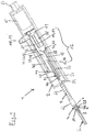
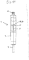
- a pipette 1 designed as a positive displacement pipette has a rod-shaped (for example cylindrical) pipette housing 2.
- a hollow cylindrical shaft 3 projects downward from the lower end of the pipette housing 2.
- a pin 4 projects downward from the lower end of the shaft 3, which according to FIG Fig. 1 and 4th a Has through hole 5 with a through hole at the lower end.
- the inside diameter of the through hole 5 is smaller than the inside diameter of the shaft 3.
- the pin 4 has an upper pin section 6 with the shape of a hollow cone and below it a lower pin section 7 with the shape of a hollow cone.
- the upper journal section 6 has a smaller cone angle than the lower journal section 7. Between the upper journal section 6 and the lower journal section 7, an annular groove 8 runs around on the outer circumference of the journal 4.
- the upper pin section 6, the annular groove 8 and the lower pin section 7 form the first means for positively connecting the pipette to a pipette tip.
- the annular groove 8 forms a clamping area 9 for a corresponding bead of a pipette tip.
- the pin 4 has slots 10, 11 running in its longitudinal direction, preferably three, which are evenly spaced around the circumference of the pin 4.
- the slots 10, 11 extend from the lower end along the pin 4.
- a drive device 12 is present in the pipette housing 2, which comprises a transmission element 13 in the form of a transmission rod 14, a transmission mechanism 15 and a drive element 16 in the form of a lifting rod 17. Furthermore, the drive device 12 comprises an operating element 18 in the form of an operating lever 19, which is firmly connected to a carrier plate 21 via a web 20.
- the carrier plate 21 has an oval shape with a wide rounded end and a narrow rounded end, the operating lever 19 protruding from the edge of the narrow rounded end.
- the carrier plate 21 has a first curved slot 22 which runs approximately parallel to the contour of the narrow rounded end.
- the carrier plate 21 has a rectangular first edge recess 23 in the middle of the first curved slot 22 on the side of the narrow rounded end.
- the lifting rod 17 is guided into the shaft 3 and the pin 4 from above.
- Fig. 4 it is hollow and provided with an axial bore 24 which extends as far as a hole 25 in the lower end of the lifting rod 17. Furthermore, it has a longitudinal slot 26 which starts at its upper end and runs in the longitudinal direction and ends in front of its lower end. Due to the longitudinal slot 26, the lifting rod 17 has a C-shaped cross section. Its lower end forms a receptacle 27 for the upper end of a piston rod.
- the lifting rod 17 has a circumferential clamping spring groove 28 in the unslotted area next to its lower end. Inside the clamping spring groove 28 there are clamping slots 29.1, 29.2 on two diametrically opposite sides in the lifting rod 17, in which the clamping spring groove 28 is open to the inside of the lifting rod 17.
- a clamping spring 30 is inserted into the clamping spring groove 28 and engages through the clamping slots 29.1, 29.2 into the inner cross section of the lifting rod 17.
- the transmission mechanism 15 is designed such that when the operating lever 19 is displaced downward one after the other, between which the operating lever 19 is displaced upward, the lifting rod 17 is alternately displaced upward and downward. As a result, by pressing the operating lever 19 downwards the lifting rod 17 are moved from a lower position to an upper position, the lifting rod 17 retains the upper position during the subsequent upward displacement of the operating lever 19 and the lifting rod 17 is shifted downward again by a subsequent pressing of the operating lever 19. This can be repeated as often as you like.
- the pipette 1 is provided with an ejection device 31.
- This comprises a cam support 32 which is rotatably supported in the pipette housing 2 and which is designed as a hollow cylindrical rotary sleeve 33.
- the outer circumference of the rotary sleeve 33 is rotatably mounted, for example, on the inner circumference of the pipette housing 2 and is supported at the upper and lower end between shoulders of steps on the inner circumference of the pipette housing 2, so that it cannot be displaced in the axial direction in the pipette housing 2.
- the axis of rotation of the rotary sleeve 33 coincides with the longitudinal axis of the pipette housing 2 and the longitudinal axis of the pin 4.
- the rotating sleeve 33 has recesses 34, 35 parallel to its axis of rotation on two diametrically opposite sides which extend from the upper edge of the rotating sleeve 33 and end at a distance from its lower edge. Below the recesses, the rotating sleeve 33 thus consists of a circular base 36 and above it consists of two sectors 37, 38 of a circular ring that are diametrically opposite one another and which laterally delimit the two recesses 34, 35.
- a first curve 39 and a second curve 40 are arranged on the outer circumference of the circular base 36 of the rotary sleeve 33.
- the first curve 39 is designed as a first groove 41 in the form of an inverted Y (turned upside down).
- the vertical part 42 of the Y extends far up on a sector 37 to shortly in front of the upper edge of the sector 37.
- the second curve 40 is a second groove 43 on the outer circumference of the base 36 of the rotating sleeve 33 with the shape of an upright V.
- the first curve 39 and the second curve 40 are offset by 90 ° to one another arranged on the circumference of the rotary sleeve.
- the first curve 39 and the second curve 40 each extend over an angular range of less than 90 ° over the circumference of the rotary sleeve 33.
- the ejection device 31 comprises a first elongated sensing element 44 (ejection rod), which comprises a strip-shaped upper ejection rod section 45 and a cylindrical lower ejection rod section 46.
- the upper and lower ejector rod sections 45, 46 are arranged parallel to one another and laterally offset from one another.
- the lower end of the upper ejector rod section 45 is connected to the upper end of the lower ejector rod section 46 via a strip-shaped connecting rod section 47 inclined obliquely to the two ejector rod sections.
- a second scanning element 48 in the form of a first guide pin 49 protrudes vertically from the inside of the upper ejection rod section 45.
- the first scanning element 44 is preferably formed in one piece, for example from a rigid plastic or from metal.
- the first scanning element 44 is guided with the first guide pin 49 in the first groove 41, engages with the connecting rod section 47 through the longitudinal slot 26 of the lifting rod 17 and extends with the lower ejection rod section 46 within the lifting rod 17 to just before the lower end of the same.
- the pipette 1 comprises a locking device 50 which comprises a locking sleeve 51 and a strip-shaped control rod 52 parallel thereto.
- the upper end of the locking sleeve 51 and the lower end of the control rod 52 are connected to one another via a second connecting rod section 53 which is inclined at an angle to the locking sleeve 51 and to the control rod 52.
- a third scanning element 54 in the form of a second guide pin 55 protrudes from the inside of the control rod 52.
- the second guide pin 55 is guided in the second groove 43.
- the locking sleeve 51 is inserted into the shaft 3 from above and rests against the inside of the pin 4.
- the lifting rod 17 and the elongated first scanning element 44 are inserted into the locking sleeve 51 from above.
- the operating element 18 is pushed with the first curved slot 22 onto the sector 37 of the rotary sleeve 33 on which the first groove 41 extends.
- the rotary sleeve 33 is connected at the top to a support ring 56 which bridges the two sectors 37, 38 and stabilizes the rotary sleeve 33.
- the support ring 56 has on the outer edge a downwardly protruding jacket 57 which laterally surrounds the two sectors 37, 38 at the outer edges. It also has a second curved slot 58 which receives the upper edge of the sector 38 which is not provided with a groove 41, 43.
- On the diametrically opposite side of the jacket 57 there is a downwardly opened rectangular second edge recess 59 which is designed to accommodate the web 20 between the operating lever 19 and the carrier plate 21.
- the support ring 56 is connected to the rotary sleeve 33, for example by gluing and / or in a form-fitting manner.
- the rotary sleeve 33 and the locking sleeve 51 as well as the operating element 18 are made, for example, of one or more rigid plastics and / or of metal.
- the rotary sleeve 33, the support ring 56, the operating element 18 and / or the locking sleeve 51 are preferably each formed in one piece.
- An operating button of the operating element 18 can also be made of an elastic or soft elastic plastic or rubber.
- the operating lever 19 protrudes from the pipette housing 2 through a first housing slot 60 running transversely to the longitudinal axis of the pipette housing 2 and extending over part of the circumference of the pipette housing 2 so that it can be operated from the outside.
- the first housing slot 60 is connected in the middle to a second housing slot 61 running downward in the longitudinal direction of the pipette housing 2.
- the operating lever 19 can be displaced downward from the support ring 56 along the second housing slot 612 against the action of a spring device, sliding with the first curved slot 22 on the sector 37 of the rotating sleeve 33. After relief, the spring device automatically moves the operating lever 19 back upwards.
- a sleeve-shaped fourth scanning element 62 is guided on the outside of the shaft 3.
- a spring device in the form of a helical spring 63 guided on the shaft is supported on the underside of the pipette housing 2 and on the upper side of the fourth scanning element 62.
- the fourth scanning element 62 is pressed from above against a stop element on the shaft 3 or pin 4 by the helical spring 63.
- the pipette housing 2 On the top of the pipette housing 2 there is an adjusting button 64 for adjusting a dosing volume.
- the dosing volume can be set by turning the adjusting knob 64.
- a counter 65 arranged underneath in the pipette housing 2 shows the respectively set dosing volume.
- the adjustment knob 64 and / or the counter 65 is coupled to the transmission mechanism 15.
- the transmission mechanism 15 is designed to change the stroke of the lifting rod 17, which is carried out by shifting the operating element 18 downwards, in accordance with the metering volume set in each case.
- a pipette tip 66 which comprises a tip cylinder 67 and a tip piston 68, is pushed onto the pin 4.
- the tip cylinder 67 has a tubular body 69 which has a tip opening 70 at the lower end, a collar 72 having a push-on opening 71 at the upper end and a connecting area 73 on the inner circumference of the collar 72 for clamping onto the pin 4.
- the connection area 73 has a complementary contour to the pin 4, which has a conical lower connection section 74 at the bottom for receiving the conical lower pin section 7, above a circumferential bead 75 for engaging in the annular groove 8 of the pin 4 and above a conical upper connection section 76 for receiving the having cylindrical upper pin portion 6.
- the lower connecting section 74, the bead 75 and the upper connecting section 76 form second means for positively connecting the pipette tip 66 to the pipette 1.
- the tubular body 69 has a cylindrical piston running area 77. Below that, the tubular body 69 has a downwardly tapering tip section 78 with the shape of a hollow truncated cone.
- the tip portion 78 is in Fig. 4 shown and omitted in the remaining drawings for the sake of simplicity.
- the tip piston 68 is inserted into the tubular body 69.
- This comprises a piston 79 which is guided in the piston running area 77.
- a piston rod 80 stands from the piston 79 and has a smaller diameter than the piston 79 has, upwards in front.
- the piston rod 80 has a lower rod section 81 with a larger diameter and above it an upper rod section 82 with a smaller diameter than the lower rod section 81.
- the piston rod 80 On the lower rod section 81, the piston rod 80 has an externally encircling clamping groove 83.
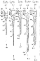
- a pipette tip family comprises five different types of pipette tips. These are pipette tips 66.1 to 66.5 with different nominal volumes of 10 ⁇ l ( Figure 12a ), 25 ⁇ l ( Figure 12b ), 100 ⁇ l ( Figure 12c ), 250 ⁇ l (Fig. D) and 1000 ⁇ l ( Figure 12e ). With all pipette tips 66.1 to 66.5 from Fig. 12 the tip piston 68.1 to 68.5 is in a position in which it is pushed as deep as possible into the tip cylinder 67.1 to 67.5.
- the tip piston 68.1 to 68.3 is pushed into the tip cylinder 67.1 to 67.3 by placing one on the tip piston 68.1 to 68.3 between piston rod 80.1 to 80.3 and piston 79.1 to 79.3 arranged disk 84.1 to 84.3 limited to a paragraph 85.1 to 85.3 in the tip cylinder 67.1 to 67.3.
- the two larger pipette tips 66.4, 66.5 with a nominal volume of 250 ⁇ l and 1000 ⁇ l also have a disk 84.4, 84.5 which is used to center the tip piston 68.4, 68.5 in the tip cylinder 67.4, 67.5.
- the lowest position of the tip piston 68.4 to 68.5 is (additionally) defined by placing a conical piston 79.4 to 79.5 on a conical tip section 78.4 to 78.5 at the lower end of the tip cylinder 67.3 to 67.5.
- the different nominal volumes are characterized by the different heights of the collar 72.1 to 72.5 of the tip cylinder 67.1 to 67.5.
- the height of the collar 72.1 to 72.5 is given by the distance between the upper edge of the collar and the bead 75.1 to 75.5.
- the pipette tips 66.1, 66.3 with a nominal volume of 10 ⁇ l and 100 ⁇ l form a first subfamily 86.1.
- the upper ends of the piston rods 80.1, 80.3 in the lowest position of the tip pistons 68.1, 68.3 assume the same positions above seat areas 87.1, 87.3, which are defined by the circumferential bead 75.1, 75.3.
- the pipette tips 66.2, 66.4 with a nominal volume of 25 ⁇ l and 250 ⁇ l form a second subfamily 86.2.
- the upper ends of the piston rods 80.2, 80.4 in the lowest position of the tip pistons 68.2, 68.4 have the same position below the seat areas 87.2, 87.4, which are defined by the beads 75.2, 75.4.
- the pipette tip 66.5 with a nominal volume of 1000 ⁇ l forms a third subfamily 86.3. This consists of only one family member. In this subfamily 86.3, the upper end of the piston rod 80.5 is arranged in the lowest position of the tip piston 68.5 approximately at the level of the upper edge of the seat area 87.5, which is defined by the bead 75.5.
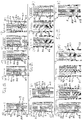
- the pipettes 1.1 to 1.3 are designed differently for pipetting with different pipette tips 66.1 to 66.5.
- the pipette 1.3 is designed for pipetting with pipette tips 66.5 of the third subfamily 86.3 in the range from 100 ⁇ l to 1000 ⁇ l.
- the pipette 1.1 is designed for pipetting with pipette tips 66.1, 66.3 of the first subfamily 86.1 in the range from 1 ⁇ l to 100 ⁇ l.
- the pipette 1.2 is designed for pipetting with pipette tips 66.2, 66.4 of the second subfamily 86.2 in the range from 2.5 ⁇ l to 250 ⁇ l.
- the tip piston 68 is each arranged in the lowest position in the tip cylinder 67.
- the position which the upper end of the piston rod 80 assumes in this situation is referred to in this application as the "starting position".
- Figure 13a shows the pipette 1.3 for pipetting volumes up to 1000 ⁇ l with an attached pipette tip 66.5 with a nominal volume of 1000 ⁇ l.
- the upper end of the piston rod 80.5 is approximately at the same level as the upper edge of the bead 75.5 of the tip cylinder 67.5.
- the collar 72.5 of the pipette tip 66.5 projects upwards with respect to the bead 75.5 over a length specific to the pipette tip 66.5 with a nominal volume of 1000 ⁇ l.
- the pipette tip 66.1 cannot be used with the pipette 1.3.
- the upper edge of the collar 72.1 presses the fourth scanning element 62 against an upper stop so that the pipette tip 66.1 cannot be pushed any further onto the pin 4.
- the piston rod 80.1 does not press the first scanning element 44 upward enough into the pipette 1.3, so that the operating element 18 is not shifted into the pipetting position in the center of the first housing slot 60 via the second housing slot 61.
- the position of the operating element 18 pivoted to the side in the first housing slot 60 prevents pipetting.
- a pipette tip 66.1 with a nominal volume of 10 ⁇ l is attached to the pipette 1.1 for pipetting volumes of up to 100 ⁇ l.
- the upper end of the piston rod 80.1 projects upwards over a certain length with respect to the bead 75.1 of the tip cylinder 67.1.
- the collar 72.1 of the pipette tip 66.1 extends over a length with respect to the bead 75.1 above, which is specific for the pipette tip 66.1 with a nominal volume of 10 ⁇ l.
- a pipette tip 66.3 with a nominal volume of 100 ⁇ l is attached to the pipette 1.1.
- the upper end of the piston rod 80.3 projects by the same height above the bead 75.3 as in the case of the pipette tip 66.1.
- the collar 72.3 of the pipette tip 66.3 projects upwards from the bead 75.3 over a length which is specific for the pipette tip 66.3.
- a pipette tip 66.2 with a nominal volume of 25 ⁇ l is attached to the pipette 1.2 for pipetting samples with a volume of up to 250 ⁇ l.
- the upper end of the piston rod 80.2 of the pipette tip 66.2 is arranged a certain length below the bead 75.2.
- the collar 72.2 of the pipette tip 66.2 projects upward with respect to the bead 75.2 by a length which is specific for the pipette tip 66.2.
- a pipette tip 66.4 with a nominal volume of 250 ⁇ l is attached to the pipette 1.2.
- the upper end of the piston rod 80.4 of the pipette tip 60.4 is arranged below the bead 75.4 by the same length as in the case of the pipette tip 66.2.
- the collar 72.4 of the pipette tip 66.4 projects upward by a length with respect to the bead 75.4 which is specific for the pipette tip 66.4.
- piston rods 80.1, 80.3 and 80.5 of the pipette tips 66.1, 66.3 and 66.5 are each too long, so that from the to Figure 13c pipetting is not possible.
- the ejection device 31 and the blocking device 50 are components of a mechanical control device 88 coupled to the first scanning element 44, which puts the pipette 1 into a state that enables or does not enable pipetting depending on the scanned piston rod 80.
- the pipette 1 can be used as follows: According to Fig. 1 and 8th a pipette tip 66 is held on the pipette 1 in an initial state.
- the seat area 87 is positively connected to the pin 4 by the bead 75 engaging in the annular groove 8.
- the operating element 18 is in the starting position at the upper end of the second housing slot, in which the first housing slot can be rotated in both directions.
- the maximum angle of rotation is limited by the extent of the first and second grooves 41, 43 in the circumferential direction or of the first housing slot, depending on which extent is smaller.
- the locking sleeve 51 is according to Fig. 4 arranged in the lowest position, so that it prevents unintentional detachment of the pipette tip 66 from the pin 4. A radial constriction would be required to break the positive connection of the pin 4 is required, which the locking sleeve 51 does not allow in this position.
- the tip piston 68 is clamped with the upper rod section 82 in the receptacle 27 of the lifting rod 17.
- the fourth scanning element 62 is pressed against the upper edge of the pipette tip 66 by the pretensioned helical spring 63.
- the position of the fourth scanning element 62 depends on the height of the collar 72 of the attached pipette tip 66 or on the length by which the collar 72 protrudes with respect to the bead 75.
- the height of the collar 72 is indicative of the nominal volume of the pipette tip 66 used.
- the fourth scanning element 62 is coupled to a diaphragm or other range setting device on the counter 65 via a slide (not shown) or another transmission device.
- the counter 65 indicates the volume that can be pipetted with the respective attached pipette tip 66 during the stroke set by means of the operating element 18.
- Embodiments of the pipette which has a scanning device for scanning the height of the collar of the pipette tip, as well as a family of pipette tips in which pipette tips of different types (eg with different nominal volumes) have collars of different heights, are described in the European patent application EP 18 168 763.3 described.
- the pipette 1 with the lower end of the pipette tip 66 held on it is immersed in a liquid. Thereafter, the operating element 18 is pressed down. This movement is converted by the transmission device 15 into a lifting movement of the lifting rod 17. As a result, the tip piston 68 is displaced upward.
- the upper rod section 82 takes the first scanning element 44 with it, so that the first guide pin 49 in the vertical part 42 of the Y-shaped first groove 41 upwards slides. Meanwhile, the locking sleeve 45 maintains its position. This is in Fig. 9 shown.
- the pipette tip 66 When the operating element 18 has carried out the set stroke, the pipette tip 66 is filled with a certain amount of liquid. The operating element 18 is then relieved and displaced back upwards by the spring device until it rests on the support ring 56. In order to dispense this amount of liquid, the pipette 1 with the pipette tip 66 can be aligned with another vessel. By pressing the operating element 18 downwards again, the lifting rod 17 is shifted downwards and the amount of liquid is dispensed. Here, the first guide pin 49 slides down to the junction of the first groove 41.
- the stroke performed by the operating element 18 when the liquid is taken up and dispensed depends on the set amount of liquid.
- the uptake and release of liquid can be carried out several times.
- the operating element 18 is pivoted from the pipetting position to the right or to the left into an ejection position. This rotates the rotary sleeve 33 so that the second groove 43 displaces the second guide pin 55 and thus the locking sleeve 51 upwards until the locking sleeve 51 has released the pin 4 to such an extent that it can be deformed radially inward.
- the locking sleeve 51 is preferably pulled out of the through hole 5.
- the first guide pin 49 is displaced downward in one of the two lateral sections of the lower part of the first groove 41, so that the first sensing element 44 presses against the tip piston 68, which is supported at the bottom on the tip section 78.
- the bead 75 exerts a radial force on the pin 4, so that the latter narrowed and the positive connection between pipette tip 66 and pin 4 is dissolved.
- the pipette tip 66 is released from the pin 4. This is in Fig. 10 shown.
- the stripping of the pipette tip 66 from the pin 4 can also be assisted by the fourth scanning element 62, which is pressed by the pretensioned helical spring 63 against the upper edge of the pipette tip 66.
- a new pipette tip 66 can be connected to the peg 4.
- the pipette 1 with the pin 4 can be inserted into the plug-on opening 71 of a pipette tip 66 held ready in a carrier.
- the fourth scanning element 62 is displaced upwards and the helical spring 63 is pretensioned.
- the display of the counter 65 is set to the attached pipette tip 66.
- the upper rod section 82 presses against the underside of the first scanning element 44, so that the first guide pin 49 slides as far as the first branch point of the first groove 41.
- the rotary sleeve 33 is rotated in the pipette housing 2 until the operating element 18 is in the pipetting position.
- the second guide pin 55 slides to the lowest point in the second groove 43.
- the locking sleeve 51 is in the locking position of Fig. 4 relocated, in which it prevents detachment of the pipette tip 66 from the pin 4.
- connection of the tip piston 68 to the lifting rod 17 and the pipetting can take place in the manner described above.
- a pipette tip 66.6 is shown, which extends from the pipette tip 66.5 of Figure 15e differs in that the piston rod 80.6 has a stop 89 below the clamping groove 83.6 at the lower end of the lower rod section 81.6.
- the stop 89 is formed by the top of a conical section 90 that widens upwards.
- the stop 89 is through the top of a disk or through several outwardly projecting projections distributed at the same height over the circumference of the piston rod 80.6.
- the stop 89 is positioned such that the piston rod 80.6 can be pushed so far into the receptacle 27 that the clamping spring 30 engages in the clamping groove 83.6.
- the abutment of the stop 89 on the edge of the hole 25 prevents the piston rod 80 from being pushed into the receptacle 27 any further.
- the tip piston 68.6 can only be pulled out of the receptacle 27 by overcoming the clamping force of the clamping spring 30. As a result, the tip piston 68.6 is held immovably by the lifting rod 17 both upwards and downwards. This avoids pipetting errors when aspirating and dispensing the liquid.
Landscapes
- Health & Medical Sciences (AREA)
- Clinical Laboratory Science (AREA)
- Chemical & Material Sciences (AREA)
- Chemical Kinetics & Catalysis (AREA)
- Devices For Use In Laboratory Experiments (AREA)
Priority Applications (6)
| Application Number | Priority Date | Filing Date | Title |
|---|---|---|---|
| EP19214095.2A EP3831486A1 (fr) | 2019-12-06 | 2019-12-06 | Famille de pointes de pipette comprenant les pointes de pipette destinées à l'utilisation avec des pipettes d'une famille de pipettes et famille de pipettes comprenant les pipettes destinées à l'utilisation avec des pointes de pipette d'une famille de pointes de pipette |
| EP20819738.4A EP4069426A1 (fr) | 2019-12-06 | 2020-12-04 | Famille d'embouts de pipette et famille de pipettes |
| PCT/EP2020/084608 WO2021110902A1 (fr) | 2019-12-06 | 2020-12-04 | Famille d'embouts de pipette et famille de pipettes |
| CN202080083190.1A CN114786816B (zh) | 2019-12-06 | 2020-12-04 | 移液器吸头套件、移液器套件和移液器系统 |
| JP2022533571A JP7465349B2 (ja) | 2019-12-06 | 2020-12-04 | ピペット・ファミリのピペットで使用するピペット・チップを備えたピペット・チップ・ファミリ、およびピペット・チップ・ファミリのピペット・チップで使用するピペットを備えたピペット・ファミリ |
| US17/782,866 US20220401945A1 (en) | 2019-12-06 | 2020-12-04 | Pipette tip family comprising pipette tips for use with pipettes of a pipette family and pipette family comprising pipettes for use with pipette tips of a pipette tip family |
Applications Claiming Priority (1)
| Application Number | Priority Date | Filing Date | Title |
|---|---|---|---|
| EP19214095.2A EP3831486A1 (fr) | 2019-12-06 | 2019-12-06 | Famille de pointes de pipette comprenant les pointes de pipette destinées à l'utilisation avec des pipettes d'une famille de pipettes et famille de pipettes comprenant les pipettes destinées à l'utilisation avec des pointes de pipette d'une famille de pointes de pipette |
Publications (1)
| Publication Number | Publication Date |
|---|---|
| EP3831486A1 true EP3831486A1 (fr) | 2021-06-09 |
Family
ID=68808155
Family Applications (2)
| Application Number | Title | Priority Date | Filing Date |
|---|---|---|---|
| EP19214095.2A Pending EP3831486A1 (fr) | 2019-12-06 | 2019-12-06 | Famille de pointes de pipette comprenant les pointes de pipette destinées à l'utilisation avec des pipettes d'une famille de pipettes et famille de pipettes comprenant les pipettes destinées à l'utilisation avec des pointes de pipette d'une famille de pointes de pipette |
| EP20819738.4A Pending EP4069426A1 (fr) | 2019-12-06 | 2020-12-04 | Famille d'embouts de pipette et famille de pipettes |
Family Applications After (1)
| Application Number | Title | Priority Date | Filing Date |
|---|---|---|---|
| EP20819738.4A Pending EP4069426A1 (fr) | 2019-12-06 | 2020-12-04 | Famille d'embouts de pipette et famille de pipettes |
Country Status (5)
| Country | Link |
|---|---|
| US (1) | US20220401945A1 (fr) |
| EP (2) | EP3831486A1 (fr) |
| JP (1) | JP7465349B2 (fr) |
| CN (1) | CN114786816B (fr) |
| WO (1) | WO2021110902A1 (fr) |
Cited By (2)
| Publication number | Priority date | Publication date | Assignee | Title |
|---|---|---|---|---|
| EP4279182A1 (fr) * | 2022-05-19 | 2023-11-22 | Eppendorf SE | Pipette pour l'utilisation avec une pointe de pipette |
| CN117916024A (zh) * | 2021-06-11 | 2024-04-19 | Spt实验室技术有限公司 | 用于液体分配设备的移液头 |
Families Citing this family (1)
| Publication number | Priority date | Publication date | Assignee | Title |
|---|---|---|---|---|
| CN115561476B (zh) * | 2022-09-29 | 2026-05-01 | 时新(上海)产品设计有限公司 | 加样设备 |
Citations (7)
| Publication number | Priority date | Publication date | Assignee | Title |
|---|---|---|---|---|
| EP0078724A1 (fr) * | 1981-10-28 | 1983-05-11 | Marteau d'Autry, Eric | Pipette de précision à déplacement positif |
| DE19948818A1 (de) | 1999-10-09 | 2001-05-10 | Retec Elektronische Regeltechn | System zum Aufnehmen und Abgeben von Fluidvolumina |
| US6749812B2 (en) | 2000-06-26 | 2004-06-15 | Vistalab Technologies | Automatic pipette detipping |
| DE102009034897A1 (de) * | 2009-07-27 | 2011-02-03 | Eppendorf Ag | Spritze, Spritzenfamilie und Dosiervorrichtung |
| EP2574402B1 (fr) | 2011-09-30 | 2015-03-18 | Eppendorf Ag | Seringue avec cylindre avec codage et des elements de controles |
| DE202017101007U1 (de) * | 2017-02-23 | 2018-05-24 | Brand Gmbh + Co Kg | Austauschbare Kolben-Zylinder-Einheit für einen Dispenser, Dispenser und System zum Aufnehmen und Abgeben von Fluidvolumina |
| EP3560596A1 (fr) * | 2018-04-23 | 2019-10-30 | Eppendorf AG | Pipette à utiliser avec une pointe de pipette et une famille de pipettes comprenant plusieurs pipettes avec des volumes nominaux différents |
Family Cites Families (15)
| Publication number | Priority date | Publication date | Assignee | Title |
|---|---|---|---|---|
| US5192511A (en) * | 1991-05-31 | 1993-03-09 | Tri-Continent Scientific, Inc. | Pipette tip and piston |
| EP0691158B1 (fr) * | 1994-07-07 | 2001-11-07 | Brand Gmbh + Co Kg | Système de pipetage |
| CN2447765Y (zh) * | 2000-09-05 | 2001-09-12 | 王振明 | 移液器 |
| FI20031681A0 (fi) * | 2003-11-19 | 2003-11-19 | Thermo Electron Oy | Sähköpipetti |
| DE102004003434B4 (de) * | 2004-01-21 | 2006-06-08 | Eppendorf Ag | Pipettiervorrichtung mit einer Verdrängungseinrichtung und einer damit lösbar verbundenen Antriebseinrichtung |
| DK2818245T3 (da) * | 2009-07-27 | 2019-10-21 | Eppendorf Ag | Sprøjte, sprøjtefamilie og doseringsindretning |
| US9156030B2 (en) * | 2011-12-28 | 2015-10-13 | Eppendorf Ag | Pipette tip |
| EP2735369B1 (fr) * | 2012-11-23 | 2017-04-26 | Eppendorf Ag | Pipette multi-canal |
| FR3012883B1 (fr) * | 2013-11-07 | 2015-12-25 | Gilson Sas | Systeme de pipetage a deplacement positif, presentant une conception facilitant la prehension du piston de l'ensemble capillaire-piston |
| WO2016055912A1 (fr) * | 2014-10-07 | 2016-04-14 | Gunnar Magnusson | Dispositif de distribution et procédé d'utilisation pour distribuer un volume défini d'un liquide |
| CN104826679A (zh) * | 2014-11-09 | 2015-08-12 | 韦伟 | 一种移液吸头及使用其的移液器 |
| FR3049877B1 (fr) * | 2016-04-12 | 2018-04-13 | Gilson Sas | Pipette pour le prelevement d'une plage etendue de volumes de liquide |
| EP3403725A1 (fr) * | 2017-05-15 | 2018-11-21 | Eppendorf AG | Système d'aide au pipetage |
| EP3575000A1 (fr) * | 2018-05-31 | 2019-12-04 | Eppendorf AG | Pointe de pipette |
| PL3680017T3 (pl) | 2019-01-08 | 2022-02-07 | Eppendorf Ag | Pipeta do używania z końcówką |
-
2019
- 2019-12-06 EP EP19214095.2A patent/EP3831486A1/fr active Pending
-
2020
- 2020-12-04 CN CN202080083190.1A patent/CN114786816B/zh active Active
- 2020-12-04 WO PCT/EP2020/084608 patent/WO2021110902A1/fr not_active Ceased
- 2020-12-04 JP JP2022533571A patent/JP7465349B2/ja active Active
- 2020-12-04 EP EP20819738.4A patent/EP4069426A1/fr active Pending
- 2020-12-04 US US17/782,866 patent/US20220401945A1/en active Pending
Patent Citations (7)
| Publication number | Priority date | Publication date | Assignee | Title |
|---|---|---|---|---|
| EP0078724A1 (fr) * | 1981-10-28 | 1983-05-11 | Marteau d'Autry, Eric | Pipette de précision à déplacement positif |
| DE19948818A1 (de) | 1999-10-09 | 2001-05-10 | Retec Elektronische Regeltechn | System zum Aufnehmen und Abgeben von Fluidvolumina |
| US6749812B2 (en) | 2000-06-26 | 2004-06-15 | Vistalab Technologies | Automatic pipette detipping |
| DE102009034897A1 (de) * | 2009-07-27 | 2011-02-03 | Eppendorf Ag | Spritze, Spritzenfamilie und Dosiervorrichtung |
| EP2574402B1 (fr) | 2011-09-30 | 2015-03-18 | Eppendorf Ag | Seringue avec cylindre avec codage et des elements de controles |
| DE202017101007U1 (de) * | 2017-02-23 | 2018-05-24 | Brand Gmbh + Co Kg | Austauschbare Kolben-Zylinder-Einheit für einen Dispenser, Dispenser und System zum Aufnehmen und Abgeben von Fluidvolumina |
| EP3560596A1 (fr) * | 2018-04-23 | 2019-10-30 | Eppendorf AG | Pipette à utiliser avec une pointe de pipette et une famille de pipettes comprenant plusieurs pipettes avec des volumes nominaux différents |
Cited By (2)
| Publication number | Priority date | Publication date | Assignee | Title |
|---|---|---|---|---|
| CN117916024A (zh) * | 2021-06-11 | 2024-04-19 | Spt实验室技术有限公司 | 用于液体分配设备的移液头 |
| EP4279182A1 (fr) * | 2022-05-19 | 2023-11-22 | Eppendorf SE | Pipette pour l'utilisation avec une pointe de pipette |
Also Published As
| Publication number | Publication date |
|---|---|
| WO2021110902A1 (fr) | 2021-06-10 |
| JP7465349B2 (ja) | 2024-04-10 |
| CN114786816B (zh) | 2023-10-31 |
| US20220401945A1 (en) | 2022-12-22 |
| CN114786816A (zh) | 2022-07-22 |
| EP4069426A1 (fr) | 2022-10-12 |
| JP2023504729A (ja) | 2023-02-06 |
Similar Documents
| Publication | Publication Date | Title |
|---|---|---|
| EP3680016B1 (fr) | Pipette destinée à une utilisation avec une pointe de pipette | |
| EP2425896B1 (fr) | Seringue pour l'utilisation à l'aide d'un dispositif de dosage | |
| EP3784399B1 (fr) | Pipette à utiliser avec une pointe de pipette et une famille de pipettes comprenant plusieurs pipettes avec des volumes nominaux différents | |
| EP3939702A1 (fr) | Pipette pour l' utilisation avec une pointe de pipette à plongeur intégré | |
| DE102007010299B4 (de) | Handpipettiervorrichtung | |
| EP1559480B1 (fr) | Pipette avec mécanisme de déplacement fixé de façon détachable au mécanisme d'actionnement | |
| DE102004003433B4 (de) | Pipettiervorrichtung mit einer Abwurfeinrichtung für Pipettenspitzen | |
| DE69937896T2 (de) | Pipette mit verbesserter pipettenspitze und verbesserter montage-achse | |
| EP3680017B1 (fr) | Pipette destinée à une utilisation avec une pointe de pipette | |
| EP3928868B1 (fr) | Pipette à utiliser avec une pointe de pipette ou une seringue comportant un piston et un cylindre | |
| EP4069426A1 (fr) | Famille d'embouts de pipette et famille de pipettes | |
| DE102007042115A1 (de) | Pipette | |
| DE69206158T2 (de) | Verdrängerpipette. | |
| DE2365947A1 (de) | Mit der hand zu haltende pipette | |
| EP2633915A2 (fr) | Pipette | |
| EP3793738A1 (fr) | Tête de pipetage, dispositif de pipetage comprenant une tête de pipetage et procédé de pipetage au moyen d'une tête de pipetage | |
| EP1759768A1 (fr) | Pipette | |
| EP3831487B1 (fr) | Pipette à utiliser avec une pointe de pipette et pointe de pipette à utiliser avec une pipette | |
| EP0331912A2 (fr) | Dispositif de réception d'echantillons remplissable pour la manipulation d'échantillons liquides | |
| EP3778028B1 (fr) | Pipette à volume de dosage réglable | |
| EP3260822B1 (fr) | Seringue multivoie pour l'utilisation a l'aide d'un dispositif de dosage | |
| EP2210667B1 (fr) | Dispositif de dosage avec éjecteur de pointe | |
| WO2008113611A1 (fr) | Procédé et dispositif pour la distribution dosée d'un milieu | |
| EP4279182B1 (fr) | Pipette pour l'utilisation avec une pointe de pipette | |
| EP3932557B1 (fr) | Tête de pipetage à canaux multiples |
Legal Events
| Date | Code | Title | Description |
|---|---|---|---|
| PUAI | Public reference made under article 153(3) epc to a published international application that has entered the european phase |
Free format text: ORIGINAL CODE: 0009012 |
|
| STAA | Information on the status of an ep patent application or granted ep patent |
Free format text: STATUS: THE APPLICATION HAS BEEN PUBLISHED |
|
| AK | Designated contracting states |
Kind code of ref document: A1 Designated state(s): AL AT BE BG CH CY CZ DE DK EE ES FI FR GB GR HR HU IE IS IT LI LT LU LV MC MK MT NL NO PL PT RO RS SE SI SK SM TR |
|
| STAA | Information on the status of an ep patent application or granted ep patent |
Free format text: STATUS: REQUEST FOR EXAMINATION WAS MADE |
|
| 17P | Request for examination filed |
Effective date: 20211208 |
|
| RBV | Designated contracting states (corrected) |
Designated state(s): AL AT BE BG CH CY CZ DE DK EE ES FI FR GB GR HR HU IE IS IT LI LT LU LV MC MK MT NL NO PL PT RO RS SE SI SK SM TR |
|
| RAP3 | Party data changed (applicant data changed or rights of an application transferred) |
Owner name: EPPENDORF SE |
|
| STAA | Information on the status of an ep patent application or granted ep patent |
Free format text: STATUS: EXAMINATION IS IN PROGRESS |
|
| 17Q | First examination report despatched |
Effective date: 20240724 |