EP2426418A1 - Dispositif de cuisson - Google Patents
Dispositif de cuisson Download PDFInfo
- Publication number
- EP2426418A1 EP2426418A1 EP10769735A EP10769735A EP2426418A1 EP 2426418 A1 EP2426418 A1 EP 2426418A1 EP 10769735 A EP10769735 A EP 10769735A EP 10769735 A EP10769735 A EP 10769735A EP 2426418 A1 EP2426418 A1 EP 2426418A1
- Authority
- EP
- European Patent Office
- Prior art keywords
- gas discharge
- cooling
- body casing
- heating chamber
- main body
- Prior art date
- Legal status (The legal status is an assumption and is not a legal conclusion. Google has not performed a legal analysis and makes no representation as to the accuracy of the status listed.)
- Withdrawn
Links
- 238000010411 cooking Methods 0.000 title claims abstract description 52
- 238000001816 cooling Methods 0.000 claims abstract description 150
- 238000010438 heat treatment Methods 0.000 claims abstract description 89
- 238000011144 upstream manufacturing Methods 0.000 claims description 3
- 239000007789 gas Substances 0.000 description 142
- XLYOFNOQVPJJNP-UHFFFAOYSA-N water Substances O XLYOFNOQVPJJNP-UHFFFAOYSA-N 0.000 description 18
- 230000005494 condensation Effects 0.000 description 5
- 238000009833 condensation Methods 0.000 description 5
- 238000010790 dilution Methods 0.000 description 5
- 239000012895 dilution Substances 0.000 description 5
- 230000003247 decreasing effect Effects 0.000 description 4
- 230000000694 effects Effects 0.000 description 4
- 239000011521 glass Substances 0.000 description 4
- 229920006395 saturated elastomer Polymers 0.000 description 4
- 238000007865 diluting Methods 0.000 description 3
- 238000012856 packing Methods 0.000 description 3
- 230000015572 biosynthetic process Effects 0.000 description 2
- 238000007664 blowing Methods 0.000 description 2
- 230000008030 elimination Effects 0.000 description 2
- 238000003379 elimination reaction Methods 0.000 description 2
- 238000003780 insertion Methods 0.000 description 2
- 230000037431 insertion Effects 0.000 description 2
- 239000004973 liquid crystal related substance Substances 0.000 description 2
- 238000005192 partition Methods 0.000 description 2
- 230000002093 peripheral effect Effects 0.000 description 2
- 150000003839 salts Chemical class 0.000 description 2
- 238000005549 size reduction Methods 0.000 description 2
- QVGXLLKOCUKJST-UHFFFAOYSA-N atomic oxygen Chemical compound [O] QVGXLLKOCUKJST-UHFFFAOYSA-N 0.000 description 1
- 229920006015 heat resistant resin Polymers 0.000 description 1
- 230000003647 oxidation Effects 0.000 description 1
- 238000007254 oxidation reaction Methods 0.000 description 1
- 239000001301 oxygen Substances 0.000 description 1
- 229910052760 oxygen Inorganic materials 0.000 description 1
- 239000000243 solution Substances 0.000 description 1
Images



Classifications
-
- F—MECHANICAL ENGINEERING; LIGHTING; HEATING; WEAPONS; BLASTING
- F24—HEATING; RANGES; VENTILATING
- F24C—DOMESTIC STOVES OR RANGES ; DETAILS OF DOMESTIC STOVES OR RANGES, OF GENERAL APPLICATION
- F24C15/00—Details
- F24C15/006—Arrangements for circulation of cooling air
-
- F—MECHANICAL ENGINEERING; LIGHTING; HEATING; WEAPONS; BLASTING
- F24—HEATING; RANGES; VENTILATING
- F24C—DOMESTIC STOVES OR RANGES ; DETAILS OF DOMESTIC STOVES OR RANGES, OF GENERAL APPLICATION
- F24C15/00—Details
- F24C15/20—Removing cooking fumes
- F24C15/2007—Removing cooking fumes from oven cavities
-
- F—MECHANICAL ENGINEERING; LIGHTING; HEATING; WEAPONS; BLASTING
- F24—HEATING; RANGES; VENTILATING
- F24C—DOMESTIC STOVES OR RANGES ; DETAILS OF DOMESTIC STOVES OR RANGES, OF GENERAL APPLICATION
- F24C15/00—Details
- F24C15/32—Arrangements of ducts for hot gases, e.g. in or around baking ovens
- F24C15/322—Arrangements of ducts for hot gases, e.g. in or around baking ovens with forced circulation
- F24C15/327—Arrangements of ducts for hot gases, e.g. in or around baking ovens with forced circulation with air moisturising
-
- H—ELECTRICITY
- H05—ELECTRIC TECHNIQUES NOT OTHERWISE PROVIDED FOR
- H05B—ELECTRIC HEATING; ELECTRIC LIGHT SOURCES NOT OTHERWISE PROVIDED FOR; CIRCUIT ARRANGEMENTS FOR ELECTRIC LIGHT SOURCES, IN GENERAL
- H05B6/00—Heating by electric, magnetic or electromagnetic fields
- H05B6/64—Heating using microwaves
- H05B6/642—Cooling of the microwave components and related air circulation systems
Definitions
- the present invention relates to a cooking device.
- the cooking device however, has a problem in that use of the multi blade fan makes the cooking device structure complicated and increases its costs.
- An object of the invention is to provide a cooking device that is capable of diluting discharge gas by a simple structure and with a low cost, without use of a separate gas discharge fan for dilution.
- a cooking device comprising:
- At least a portion of the cooling air from the cooling fan that is provided in the main body casing flows along the cooling paths, passes through the spaces in vicinity of the heaters in the main body casing, flows into the gas discharge path through the cooling path terminal opening on the gas discharge path, and is discharged. Then gas containing steam (only steam in general in oxygen-free cooking with use of superheated steam or the like) from the gas discharge opening of the heating chamber provided in the main body casing is discharged to the outside by being carried by a flow of the cooling air that has flowed from the cooling paths into the gas discharge path.
- gas containing steam only steam in general in oxygen-free cooking with use of superheated steam or the like
- the cooling air is heated by passing by the heaters, humidity of the cooling air is thereby decreased relative to humidity of the discharge gas from the heating chamber, the humidity of the discharge gas is thus decreased when the cooling air is merged and mixed with the discharge gas from the heating chamber, and condensation on surroundings is effectively prevented when the gas is discharged out of the main body casing.
- the discharge gas can be diluted by a simple structure and with a low cost, without use of a separate gas discharge fan for dilution.
- elimination of necessity of a space for placement of the gas discharge fan is advantageous for size reduction.
- the cooling fan and the gas discharge path are placed in the main body casing so as to be opposed to each other.
- the cooling fan and the gas discharge path that are placed in the main body casing so as to be generally opposed to each other facilitate formation of the flow in which the cooling air from the cooling fan passes through the cooling paths while cooling the electric components in the main body casing and goes toward the generally opposed gas discharge path in the main body casing before flowing into the gas discharge path, and make it possible to smoothly perform the cooling of the electric components and the gas discharge.
- a second cooling path having a blow-off opening through which a portion of the cooling air from the cooling fan is blown off is provided in vicinity of the external gas discharge opening of the gas discharge path.
- the second cooling path having the blow-off opening through which a portion of the cooling air from the cooling fan is blown off is provided in vicinity of the external gas discharge opening of the gas discharge path, the cooling air is therefore blown off from the blow-off opening of the second cooling path along the discharge gas blowing off from the external gas discharge opening of the gas discharge path, and thus occurrence of condensation can be prevented on outer surfaces of the main body casing in vicinity of the external gas discharge opening, wall surfaces on upper side of the external gas discharge opening and the like, particularly in steam cooking in which a great quantity of steam is discharged.
- the cooking device further comprises heater chambers which are provided on top side of the heating chamber and in which the heaters for heating the inside of the heating chamber are housed, wherein the cooling air from the cooling fan flows through the top side of the heating chamber along the heater chambers and flows into the gas discharge path.
- the cooling air from the cooling fan flows through the top side of the heating chamber along the heater chamber in which the heaters for heating the inside of the heating chamber are housed and flows into the gas discharge path, and thus outside of the heater chamber can efficiently be cooled so that increase in temperature on the top face side of the main body casing can be suppressed.
- the cooling air from the cooling fan flows along at least one side face of the heating chamber after passing through the electric component chamber and flows into the gas discharge path.
- the cooling air from the cooling fan passes through the electric component chamber in which the electric components are placed, thereafter flows along at least one side face of the heating chamber, and flows into the gas discharge path, so as to initially cool the electric components in the electric component chamber and so as to thereafter flow along at least the one side face of the heating chamber, and thus the electric components can be cooled by the cooling air that is not yet increased in temperature by heat from the heating chamber, so that increase in cooling effect improves reliability.
- the cooking device of the invention can be obtained that is capable of diluting the discharge gas by a simple structure and with a low cost, without use of a separate gas discharge fan for dilution.
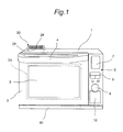
- Fig. 1 shows a front view of a cooking device in accordance with the embodiment of the invention, as viewed from front face side thereof, and Fig. 2 shows a front view of the cooking device with a door opened.
- the cooking device in accordance with the embodiment has a main body casing 1 that is shaped like a rectangular parallelepiped, a heating chamber 2 (shown in Fig. 2 ) that is provided in the main body casing 1, and a door 3 that is pivotably mounted on the front face side of the main body casing 1.
- the door 3 pivots on a lower end part thereof so as to open and close an opening 2a of the heating chamber 2.
- a handle 4 is mounted on upper part of the door 3.
- Heat-resistant glass 5 is provided generally at center part of the door 3, so that a user can observe a state of inside of the heating chamber 2 through the heat-resistant glass 5.
- packing 60 shown in Fig. 2
- the packing 60 is brought into intense and intimate contact with peripheral part of the opening 2a of the heating chamber 2 when the door 3 is closed. Thus steam and/or the like in the heating chamber 2 can be prevented from leaking out from between the door 3 and the peripheral part of the opening 2a of the heating chamber 2.
- a gas discharge duct 30 in which an external gas discharge opening 28 and a blow-off opening 29 are provided so as to form two upper and lower levels is provided as an example of a gas discharge path.
- One end of the gas discharge duct 30 is connected to an opening on a protruding part 33 (shown in Figs. 5 and 6 ) communicating with an internal gas discharge opening 19 that is shown in Fig. 2 and that is provided on back face side of the heating chamber 2.
- An operation panel 6 is provided on right side on the front face of the main body casing 1.
- the operation panel 6 has a liquid crystal display part 7, a dial 8, and a plurality of buttons 9.
- a water supply tank 10 is housed under the dial 8. The water supply tank 10 can be attached to and detached from the main body casing 1 through the front face side of the main body casing 1.
- the cooking device has a drip receiving container 50 (shown in Fig. 1 ) that is detachably mounted on underside and the front face side of the main body casing 1 and that receives water droplets dropping along the inner face of the door 3 and the front face of the main body casing 1.
- Fig. 3 is a schematic vertical section of the cooking device as viewed from right side thereof, and the same components therein as those in Figs. 1 and 2 are provided with the same reference numerals.
- reference numeral 11 denotes a water level sensor
- numeral 12 denotes a water supply pump
- numeral 13 denotes a water supply pipe
- numeral 14, 14 denote upper heaters
- numeral 15, 15 denote upper heater covers that form heater chambers for housing the upper heaters 14, 14
- numeral 16 denotes a tray on which an object 90 to be cooked is to be put
- numeral 17 denotes a lower heater
- numeral 18 denotes a heat shield plate
- numeral 19 denotes the gas discharge opening
- numeral 20 denotes a steam producing device
- numeral 24 denotes a gas discharge opening cover
- numeral 25 denotes a discharge gas thermo-sensor
- numeral 27 denotes a cool-air path
- numeral 28 denotes the external gas discharge opening
- the water supply pump 12 takes in water in the water supply tank 10 and supplies the water through the water supply pipe 13 to the steam producing device 20.
- the steam producing device 20 is capable of producing steam by heating the water from the water supply pump 12 and supplying the produced steam into the heating chamber 2, and capable of producing superheated steam by superheating the steam and supplying the superheated steam into the heating chamber 2.
- above-mentioned superheated steam refers to steam heated to a superheated state with temperatures not lower than 100°C.
- the object to be cooked 90 can be heated by the steam or the superheated steam from the steam producing device 20 and/or can be heated by radiant heat from the upper heaters 14 and the lower heater 17.
- a ceiling wall of the heating chamber 2 is provided under the upper heaters 14 and a bottom wall of the heating chamber 2 is provided above the lower heater 17. The upper heaters 14 and the lower heater 17 are not exposed in the heating chamber 2.
- Fig. 4 shows a front view of a second gas discharge duct part 32 of the cooking device.
- the second gas discharge duct part 32 is upper part of the gas discharge duct 30 shown in Figs. 1 and 2 .
- the second gas discharge duct part 32 has a sleeve part 32a that includes an insertion opening 32b on lower side thereof and that has a rectangular section, and has a bent part 32c that extends forward from an upper end of the sleeve part 32a.
- the external gas discharge opening 28 and the blow-off opening 29 are provided at an extremity of the bent part 32c of the second gas discharge duct part 32.
- the external gas discharge opening 28 communicates with the sleeve part 32a through a path formed on upper side of the bent part 32c.
- the blow-off opening 29 forms a second cooling path 34 through which cooling air flows, under the path on the upper side of the bent part 32c.
- Fig. 5 shows a rear view of an important part of the cooking device, and the same components therein as those shown in Figs. 1 and 2 are provided with the same reference numerals.
- the protruding part 33 that protrudes outward toward the back face side is provided in a position corresponding to the internal gas discharge opening 19 (shown in Fig. 2 ) provided on the back face of the heating chamber 2.
- An inner space in the protruding part 33 communicates with the inside of the heating chamber 2 through the internal gas discharge opening 19.
- a hole 33a that is generally rectangular is provided on upper side on the protruding part 33 of the heating chamber 2.
- a lower end of a first gas discharge duct part 31 that has a rectangular section is connected to the hole 33a on the protruding part 33, and an upper end of the first gas discharge duct part 31 is inserted into and fixed to the insertion opening 32b (shown in Fig.
- the gas discharge duct 30 is composed of the first gas discharge duct part 31 and the second gas discharge duct part 32.
- the cool-air introducing opening 31a is provided on a side facing the heating chamber 2 on the first gas discharge duct part 31.
- Fig. 6 shows a side view of the important part of the cooking device, and the same components therein as those shown in Figs. 1 and 2 are provided with the same reference numerals.
- the bent part 32c of the second gas discharge duct part 32 extends forward along the top face of the main body casing 1.
- Fig. 7 shows a top plan view of the important part of the cooking device, and the same components therein as those shown in Figs. 1 and 2 are provided with the same reference numerals.
- Three slots 35 communicating with the second cooling path 34 (shown in Fig. 6 ) in the gas discharge duct 30 are provided on the main body casing 1 under the gas discharge duct 30 (the bent part 32c of the second gas discharge duct part 32) extending forward (downward in Fig. 7 ) along the top face of the main body casing 1. Shapes, positions, and the like of the slots may adequately be designed according to a configuration of the second cooling path.
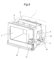
- cooling air from the cooling fan 40 passes through cooling paths shown in Figs. 8 and 9 , flows into the gas discharge duct 30, and is then discharged.
- Fig. 8 shows a perspective view of the front face side of the cooking device, as viewed diagonally from above, and the same components therein as those shown in Figs. 1 and 2 are provided with the same reference numerals.
- an electric component chamber S in which electric components are placed is formed at right of the heating chamber 2 placed in the main body casing 1.
- Back face side of the electric component chamber S is partitioned with a partition plate 41.
- the cooling fan 40 for delivering cooling air from the back face side into the electric component chamber S is placed under the partition plate 41.
- An outside-air intake 100 is provided behind the cooling fan 40 on the main body casing 1, so that outside air is taken in by the cooling fan 40 through the outside-air intake 100 and is blown off as the cooling air from the cooling fan 40.
- a portion of the cooling air from the cooling fan 40 passes through right side surface side of the heating chamber 2 while cooling the electric components in the electric component chamber S, and flows through the top face side of the heating chamber 2 toward left side along the upper heater covers 15, 15.
- another portion of the cooling air from the cooling fan 40 flows to lower right side of the heating chamber 2 while cooling the electric components in the electric component chamber S, and flows through the bottom face side of the heating chamber 2 toward the left side.
- the outside-air intake 100 is provided on the rear face side of the main body casing 1 and the cooling fan 40, whereas outside-air intake openings may appropriately be provided on other sites such as the bottom face and the back face of the main body casing.
- the cooling paths are formed that extend from the outside-air intake 100 through the cooling fan 40 and the electric component chamber S to the cool-air introducing opening 31a of the gas discharge duct 30.
- Fig. 9 shows a perspective view of back face side of the cooking device, as viewed diagonally from below, and the same components therein as those shown in Figs. 1 and 2 are provided with the same reference numerals.
- the steam producing device 20 is placed at center of the back face side of the heating chamber 2, and the gas discharge duct 30 is placed at left (right side in Fig. 9 ) thereof.
- the portion of the cooling air delivered from the cooling fan 40 into the electric component chamber S flows through the bottom face side of the heating chamber 2 toward the left side (right side in Fig. 9 ) and the back face side of the heating chamber 2 while cooling the electric components in the electric component chamber S, and passes through the back face side or the left side face side (right side in Fig. 9 ) of the heating chamber 2, and the cooling air flows into the first gas discharge duct part 31 through the cool-air introducing opening 31a on the first gas discharge duct part 31.
- the cooling paths of the cooking device have a route from the electric component chamber S through the top face side and the left side face side of the heating chamber 2 to the cool-air introducing opening 31a on the first gas discharge duct part 31 on the back face side, a route from the electric component chamber S through the bottom face side and the left side face side of the heating chamber 2 to the cool-air introducing opening 31a on the first gas discharge duct part 31 on the back face side, and a route from the electric component chamber S through the bottom face side and the back face side of the heating chamber 2 to the cool-air introducing opening 31a on the first gas discharge duct part 31.
- a heat shield plate 70 that intercepts heat from the heating chamber 2, that receives condensate water deposited on surfaces of the heating chamber 2, and that guides the condensate water into the drip receiving container 50 is provided on the bottom face side of the heating chamber 2.
- a portion of the cooling air delivered from the cooling fan 40 into the electric component chamber S passes through the bottom face side of the heating chamber 2 via a route through underside of the heat shield plate 70 and a route through between the bottom face of the heating chamber 2 and the heat shield plate 70.
- structures in the main body casing 1 are designed so that air flow through the cooling paths, that is, the air routes by which the cooling air flows into the gas discharge duct 30 are ensured.
- the structures in the main body casing 1 are designed so that air flow through the second cooling path 34, that is, an air route by which the cooling air is blown off from the blow-off opening 29 through the three slots 35 provided on the main body casing 1 and the second cooling path 34 in the gas discharge duct 30 is ensured.
- the cooling air is heated by passing near the heaters 14, 14, humidity of the cooling air is thereby decreased relative to humidity of the discharge gas from the heating chamber 2, the humidity of the discharge gas is thus decreased when the cooling air is merged and mixed with the discharge gas from the heating chamber 2, and condensation on surroundings is effectively prevented when the gas is discharged out of the main body casing 1.
- the discharge gas can be diluted by the simple structure and with a low cost, without use of a separate gas discharge fan for dilution.
- the gas flows into the gas discharge duct 30 through the cooling paths running through the bottom face side, the top face side, the left side face side, the right side face side, and the back face side of the heating chamber 2 and is discharged therefrom, in the embodiment, whereas the gas may be made to flow into the gas discharge duct 30 through cooling paths running through at least one side face of the heating chamber 2 and may be discharged therefrom.
- at least one side face of the heating chamber refers to at least one of the bottom face side, the top face side, the left side face side, the right side face side, and the back face side thereof except the front face side having the opening.
- the placement of the cooling fan 40 and the gas discharge duct 30 in positions generally opposed to each other with the placement of the cooling fan 40 on lower right side in the main body casing 1 and the placement of the gas discharge duct 30 on upper left side in the main body casing 1 facilitates formation of the flow in which the cooling air from the cooling fan 40 passes through the cooling paths while cooling the electric components in the main body casing 1 and goes toward the generally opposed gas discharge duct 30 in the main body casing 1 before flowing into the gas discharge duct 30, and makes it possible to smoothly perform the cooling of the electric components and the gas discharge.
- the cooling air blows off from the blow-off opening 29 of the second cooling path 34 along the discharge gas blowing off from the external gas discharge opening 28 of the gas discharge duct 30 and thus occurrence of condensation is prevented on outer surfaces of the main body casing 1 in vicinity of the external gas discharge opening 28, wall surfaces on upper side of the external gas discharge opening 28 and the like, particularly in steam cooking in which a great quantity of steam is discharged.
- a position of the blow-off opening of the second cooling path is not limited thereto but may adequately be set according to a structure of the second cooling path.
- the cooling air from the cooling fan 40 flows through the top side of the heating chamber 2 along the upper heater covers 15, 15 in which the upper heaters 14, 14 for heating the inside of the heating chamber 2 are housed and flows into the gas discharge duct 30, and thus outside of the upper heater covers 15, 15 can efficiently be cooled so that increase in temperature on the top face side of the main body casing 1 can be suppressed.
- the cooling air from the cooling fan 40 passes through the electric component chamber S in which the electric components are placed, thereafter flows along the bottom face, the top face, the left side face, the right side face, and the back face of the heating chamber 2, and flows into the gas discharge duct 30, so as to initially cool the electric components in the electric component chamber S and so as to thereafter flow along the bottom face, the top face, the left side face, the right side face, and the back face of the heating chamber 2, and thus the electric components can be cooled by the cooling air that is not yet increased in temperature by heat from the heating chamber 2, so that increase in cooling effect improves reliability.
- the cooling air may be made to flow into the gas discharge duct 30 through cooling paths running through at least one side face of the heating chamber 2 and may be discharged therefrom.
- the opening 2a of the heating chamber 2 is opened and closed by the door 3 of pivoting type in the embodiment, whereas the opening of the heating chamber may be opened and closed by a door that slides in to-and-fro directions relative to the main body casing 1, for instance. That is, the door which the cooking device of the invention includes may be of the pivoting type or of the slide type.
- healthy cooking can be performed by use of superheated steam or saturated steam in a microwave oven or an oven.
- superheated steam or saturated steam having a temperature not lower than 100°C is supplied onto surfaces of food, the superheated steam or saturated steam deposited onto the surfaces of the food condenses and gives the food a great quantity of latent heat of condensation, therefore heat can efficiently be transmitted to the food.
- the condensate water is deposited on the surfaces of the food, and salt content, oil content and the like drop with the condensate water, so that salt content, oil content and the like in the food can be reduced.
- the heating chamber is filled with the superheated steam or saturated steam so as to be absent from oxygen, and thus cooking by which oxidation of the food is suppressed can be performed.
- the cooking device of the invention has the main body casing, the heating chamber which is provided in the main body casing and on which the gas discharge opening is provided, the gas discharge path having one end connected to the gas discharge opening on the heating chamber, the cooling fan which is provided in the main body casing and which is intended for cooling the electric components, and the cooling paths in which the cooling air from the cooling fan passes through at least one side face side of the heating chamber, flows into the gas discharge path, and is discharged, and is characterized in that no fans exist in the gas discharge path.
- the phrase “at least one side face side of the heating chamber” refers to at least one of the bottom face side, the top face side, the left side face side, the right side face side, and the back face side, except the front face side having the opening.
- the cooling air from the cooling fan provided in the main body casing flows into the gas discharge path through the cooling paths that run through at least one side face side of the heating chamber, and is discharged therethrough.
- gas containing steam only steam in general in oxygen-free cooking with use of superheated steam or the like
- the discharge gas can be diluted by the simple structure and with a low cost, without use of a separate gas discharge fan for dilution.
- elimination of necessity of a space for placement of the gas discharge fan is advantageous for size reduction.
Landscapes
- Engineering & Computer Science (AREA)
- Chemical & Material Sciences (AREA)
- Combustion & Propulsion (AREA)
- Mechanical Engineering (AREA)
- General Engineering & Computer Science (AREA)
- Physics & Mathematics (AREA)
- Electromagnetism (AREA)
- Electric Ovens (AREA)
- Electric Stoves And Ranges (AREA)
- Baking, Grill, Roasting (AREA)
- Cookers (AREA)
Applications Claiming Priority (2)
| Application Number | Priority Date | Filing Date | Title |
|---|---|---|---|
| JP2009109761 | 2009-04-28 | ||
| PCT/JP2010/057450 WO2010126037A1 (fr) | 2009-04-28 | 2010-04-27 | Dispositif de cuisson |
Publications (1)
| Publication Number | Publication Date |
|---|---|
| EP2426418A1 true EP2426418A1 (fr) | 2012-03-07 |
Family
ID=43032181
Family Applications (1)
| Application Number | Title | Priority Date | Filing Date |
|---|---|---|---|
| EP10769735A Withdrawn EP2426418A1 (fr) | 2009-04-28 | 2010-04-27 | Dispositif de cuisson |
Country Status (5)
| Country | Link |
|---|---|
| US (1) | US8785828B2 (fr) |
| EP (1) | EP2426418A1 (fr) |
| JP (1) | JP5318201B2 (fr) |
| CN (1) | CN102388271B (fr) |
| WO (1) | WO2010126037A1 (fr) |
Cited By (1)
| Publication number | Priority date | Publication date | Assignee | Title |
|---|---|---|---|---|
| EP2991449A1 (fr) * | 2014-08-29 | 2016-03-02 | Miele & Cie. KG | Appareil de cuisson |
Families Citing this family (14)
| Publication number | Priority date | Publication date | Assignee | Title |
|---|---|---|---|---|
| JP4843100B1 (ja) * | 2010-08-31 | 2011-12-21 | シャープ株式会社 | 加熱調理器 |
| JP5511899B2 (ja) * | 2012-06-27 | 2014-06-04 | シャープ株式会社 | 加熱調理器 |
| CN103423784B (zh) * | 2013-05-29 | 2016-04-20 | 中山东菱威力电器有限公司 | 一种微波炉简易降温系统 |
| WO2015081549A1 (fr) * | 2013-12-05 | 2015-06-11 | 申晓星 | Récipient multifonctions pour la cuisson d'aliments |
| GB2525146B (en) * | 2014-01-17 | 2017-01-11 | Spirax-Sarco Ltd | A steam oven installation |
| DE102014112354A1 (de) * | 2014-08-28 | 2016-03-03 | Miele & Cie. Kg | Gargerät |
| US10904959B2 (en) * | 2016-11-30 | 2021-01-26 | Illinois Tool Works, Inc. | Apparatus and system for solid state oven electronics cooling |
| CN110123159A (zh) | 2017-08-09 | 2019-08-16 | 沙克忍者运营有限责任公司 | 烹饪系统 |
| TWI818052B (zh) * | 2018-08-02 | 2023-10-11 | 日商夏普股份有限公司 | 加熱調理器 |
| EP3653089A1 (fr) * | 2018-11-15 | 2020-05-20 | Koninklijke Philips N.V. | Appareil et procédé de cuisson à la vapeur |
| CA3151895A1 (fr) * | 2019-08-20 | 2021-02-25 | Sharp Kabushiki Kaisha | Appareil de cuisson chauffant en tiroir |
| JP7611507B2 (ja) * | 2020-08-28 | 2025-01-10 | パナソニックIpマネジメント株式会社 | 加熱調理器 |
| US12177955B2 (en) * | 2021-10-11 | 2024-12-24 | Whirlpool Corporation | High flow cavity ventilation |
| KR20260038030A (ko) * | 2024-09-11 | 2026-03-18 | 엘지전자 주식회사 | 조리기기 |
Family Cites Families (8)
| Publication number | Priority date | Publication date | Assignee | Title |
|---|---|---|---|---|
| JPH0228058B2 (ja) | 1983-08-31 | 1990-06-21 | Matsushita Electric Ind Co Ltd | Kanetsuchorisochi |
| JPH09273759A (ja) * | 1996-04-03 | 1997-10-21 | Toshiba Corp | 電子レンジ |
| JP2942195B2 (ja) * | 1996-06-25 | 1999-08-30 | 株式会社東芝 | 加熱調理器 |
| CN1270131C (zh) * | 2002-11-26 | 2006-08-16 | 乐金电子(天津)电器有限公司 | 微波炉的空气流动系统 |
| JP4115889B2 (ja) | 2003-06-13 | 2008-07-09 | 松下電器産業株式会社 | ビルトイン対応型加熱調理器 |
| JP2008032286A (ja) * | 2006-07-27 | 2008-02-14 | Sharp Corp | 加熱調理器 |
| JP4973065B2 (ja) * | 2006-08-23 | 2012-07-11 | パナソニック株式会社 | 加熱調理器 |
| JP4311688B2 (ja) | 2006-11-02 | 2009-08-12 | シャープ株式会社 | 排気蒸気希釈装置及びこれを備えた加熱調理器 |
-
2010
- 2010-04-27 EP EP10769735A patent/EP2426418A1/fr not_active Withdrawn
- 2010-04-27 US US13/266,387 patent/US8785828B2/en not_active Expired - Fee Related
- 2010-04-27 CN CN201080016104.1A patent/CN102388271B/zh not_active Expired - Fee Related
- 2010-04-27 WO PCT/JP2010/057450 patent/WO2010126037A1/fr not_active Ceased
- 2010-04-27 JP JP2011511410A patent/JP5318201B2/ja not_active Expired - Fee Related
Non-Patent Citations (1)
| Title |
|---|
| See references of WO2010126037A1 * |
Cited By (1)
| Publication number | Priority date | Publication date | Assignee | Title |
|---|---|---|---|---|
| EP2991449A1 (fr) * | 2014-08-29 | 2016-03-02 | Miele & Cie. KG | Appareil de cuisson |
Also Published As
| Publication number | Publication date |
|---|---|
| WO2010126037A1 (fr) | 2010-11-04 |
| CN102388271B (zh) | 2014-08-13 |
| JPWO2010126037A1 (ja) | 2012-11-01 |
| JP5318201B2 (ja) | 2013-10-16 |
| US8785828B2 (en) | 2014-07-22 |
| CN102388271A (zh) | 2012-03-21 |
| US20120043318A1 (en) | 2012-02-23 |
Similar Documents
| Publication | Publication Date | Title |
|---|---|---|
| US8785828B2 (en) | Cooking device | |
| KR102581788B1 (ko) | 냉각 시스템을 구비한 조리장치 | |
| CA2940466C (fr) | Dispositif de production de vapeur et appareil de cuisson thermique | |
| US9115903B2 (en) | Oven door | |
| US20100064902A1 (en) | Device for diluting discharged steam and cooker with the same | |
| JP5243608B2 (ja) | 加熱調理器 | |
| US20110132346A1 (en) | Cooking device | |
| US9879866B2 (en) | Cooking device | |
| CN103080654B (zh) | 加热烹调器 | |
| WO2015129619A1 (fr) | Appareil de cuisson | |
| JP5084897B2 (ja) | 加熱調理器 | |
| JP5031884B2 (ja) | 加熱調理器 | |
| JP5534686B2 (ja) | 加熱調理器 | |
| JP5511899B2 (ja) | 加熱調理器 | |
| JP5694090B2 (ja) | 加熱調理器 | |
| JP6298652B2 (ja) | 加熱調理器 | |
| JP2011231962A (ja) | 加熱調理器 | |
| JP6298653B2 (ja) | 加熱調理器 | |
| JP2015108506A (ja) | 加熱調理器 | |
| KR100767847B1 (ko) | 오븐의 공기유동 구조 | |
| JP2007322002A (ja) | 加熱調理器 |
Legal Events
| Date | Code | Title | Description |
|---|---|---|---|
| PUAI | Public reference made under article 153(3) epc to a published international application that has entered the european phase |
Free format text: ORIGINAL CODE: 0009012 |
|
| 17P | Request for examination filed |
Effective date: 20111123 |
|
| AK | Designated contracting states |
Kind code of ref document: A1 Designated state(s): AT BE BG CH CY CZ DE DK EE ES FI FR GB GR HR HU IE IS IT LI LT LU LV MC MK MT NL NO PL PT RO SE SI SK SM TR |
|
| DAX | Request for extension of the european patent (deleted) | ||
| STAA | Information on the status of an ep patent application or granted ep patent |
Free format text: STATUS: THE APPLICATION HAS BEEN WITHDRAWN |
|
| 18W | Application withdrawn |
Effective date: 20130912 |