EP2426687A2 - Modularer Sicherungshalter - Google Patents
Modularer Sicherungshalter Download PDFInfo
- Publication number
- EP2426687A2 EP2426687A2 EP11179904A EP11179904A EP2426687A2 EP 2426687 A2 EP2426687 A2 EP 2426687A2 EP 11179904 A EP11179904 A EP 11179904A EP 11179904 A EP11179904 A EP 11179904A EP 2426687 A2 EP2426687 A2 EP 2426687A2
- Authority
- EP
- European Patent Office
- Prior art keywords
- fuse
- lever arm
- fuse holder
- holder assembly
- cylindrical
- Prior art date
- Legal status (The legal status is an assumption and is not a legal conclusion. Google has not performed a legal analysis and makes no representation as to the accuracy of the status listed.)
- Withdrawn
Links
- 238000007373 indentation Methods 0.000 claims description 4
- 230000000153 supplemental effect Effects 0.000 claims description 3
- 230000000712 assembly Effects 0.000 abstract description 8
- 238000000429 assembly Methods 0.000 abstract description 8
- 238000012544 monitoring process Methods 0.000 abstract description 6
- 238000000034 method Methods 0.000 description 5
- 239000004020 conductor Substances 0.000 description 4
- 230000009977 dual effect Effects 0.000 description 3
- 230000004323 axial length Effects 0.000 description 2
- 239000012811 non-conductive material Substances 0.000 description 2
- 230000008569 process Effects 0.000 description 2
- 230000004044 response Effects 0.000 description 2
- 230000006978 adaptation Effects 0.000 description 1
- 238000012423 maintenance Methods 0.000 description 1
- 238000004519 manufacturing process Methods 0.000 description 1
- 239000000463 material Substances 0.000 description 1
- 230000013011 mating Effects 0.000 description 1
- 238000000465 moulding Methods 0.000 description 1
- 230000001012 protector Effects 0.000 description 1
- 230000009467 reduction Effects 0.000 description 1
Images


Classifications
-
- H—ELECTRICITY
- H01—ELECTRIC ELEMENTS
- H01H—ELECTRIC SWITCHES; RELAYS; SELECTORS; EMERGENCY PROTECTIVE DEVICES
- H01H9/00—Details of switching devices, not covered by groups H01H1/00 - H01H7/00
- H01H9/10—Adaptation for built-in fuses
- H01H9/104—Adaptation for built-in fuses with interlocking mechanism between switch and fuse
-
- H—ELECTRICITY
- H01—ELECTRIC ELEMENTS
- H01H—ELECTRIC SWITCHES; RELAYS; SELECTORS; EMERGENCY PROTECTIVE DEVICES
- H01H85/00—Protective devices in which the current flows through a part of fusible material and this current is interrupted by displacement of the fusible material when this current becomes excessive
- H01H85/54—Protective devices wherein the fuse is carried, held, or retained by an intermediate or auxiliary part removable from the base, or used as sectionalisers
- H01H85/545—Protective devices wherein the fuse is carried, held, or retained by an intermediate or auxiliary part removable from the base, or used as sectionalisers with pivoting fuse carrier
Definitions
- the field of the invention relates generally to overcurrent protection fuses, and more specifically, to modular fuse holders for overcurrent circuit protection.
- Fuses are widely used as overcurrent protection devices to prevent costly damage to electrical circuits.
- Fuse terminals typically form an electrical connection between an electrical power source and an electrical component or a combination of components arranged in an electrical circuit.
- One or more fusible links or elements, or a fuse element assembly is connected between the fuse terminals, so that when electrical current through the fuse exceeds a predetermined limit, the fusible elements melt and open one or more circuits through the fuse to prevent electrical component damage.
- fuse holders providing electrical interfaces for overcurrent protection fuses. Such fuse holders are typically wired into circuitry with line and load side terminals, and the fuses complete an electrical connection within the fuse holder between the line and load side terminals.
- Existing fuse holders have not completely met the needs of those in the art, and improvements are desired.
- fuses are sometimes arranged in and enclosed by a panelboard, sometimes referred to as a control panel.
- Other circuit protection components such as circuit breakers are also commonly used in combination with fuses in panelboards.
- a main service device connects a power supply to and from the panelboard, and the circuit breakers and fuses typically provide circuit protection to branch circuits being fed from the panel through the main disconnect.
- the main service device is a disconnect switch it can be used to de-energize all the branch circuits, or the individual branch circuits can be de-energized using the circuit breakers while the main disconnect remains connected and the other branch circuits are still supplied with electrical power.
- the circuit protectors e.g., the breakers and the fuses
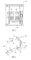
- FIG 1 is a perspective view of an exemplary fusible panelboard 100 including an exemplary modular fuse holder assembly 102 described further below.
- the panelboard 100 is configured to accommodate a number of the fuse holder assemblies 102, and in the example shown the panelboard 100 defines two generally vertical columns, designated at 104 and 106 in Figure 1 , that each can accept nine fuseholders 102 with the fuse holder assemblies 102 arranged side-by-side one another in each row.
- the panelboard 100 is adaptable, as explained in the applications referenced above, to accommodate devices other than the fuseholder assembly 102, such as fusible switch disconnect devices of various ratings and physical size. Other devices having comparable footprints and profiles may be used with the configurable panel as well.
- the particulars of the panelboard 100 are described in detail in the referenced applications above and will not be repeated herein.
- the panelboard 100 is shown for illustrative purposes only, and the fuse holder assembly 102 accordingly may be utilized with other panelboards while achieving at least some of the benefits described below.
- the panelboard 100 is therefore provided in the present discussion for purposes of illustration rather than limitation.
- Figures 2- 16 illustrate various views, components and features of the exemplary fuse holder 102.
- the fuse holder assembly 102 includes a nonconductive fuse holder body 104 including a top surface 106 and a bottom surface 108 opposing the top surface 106, left and right side surfaces 108 and 100 opposing one another and interconnecting the top and bottom surface 106 and 108, and lateral side surfaces 114 and 116 extending between and interconnecting the top, bottom, left and right surface 106, 108, 110 and 112.
- the body 104 including the surfaces 106, 108, 110, 112, 114 and 116 collectively define an enclosure or receptacle 116 (best shown in Figures 11 , 13 and 15 ) having a sufficient volume to receive a lever arm 118 and associated fuse 120 as described further below.
- the lever arm 118 may include a raised finger grip 122 that projects from the upper surface 106 of the fuse holder body 104.
- the lever arm 118 may be grasped by a user's fingers and moved between a closed position shown in Figures 2 , 4 and 7 and an opened position shown in Figures 9-11 , 13 and 15 .
- the fuse 120 In the closed position, the fuse 120 is enclosed in the body 104 in the receptacle 116, and in the open position, the receptacle 116 is exposed and the fuse 120 may be inserted into or removed from the lever arm 118. As explained below, fuse rejection features are integrated into the lever arm 118 to prevent an improper type of fuse from being installed.
- the body 104 and the lever arm 118 is configured to accommodate and accept a cylindrical fuse described further below.
- the body 104 may be formed from a nonconductive material such as plastic or another suitable material according to known techniques such as molding processes or others known in the art.
- the body 104 is formed with a compact size and profile, and has an exemplary height H ( Figure 4 ) of about 72 mm and an exemplary width W ( Figure 4 ) of about 17.5 mm or less.
- the assembly 104 may be dimensionally compliant to DIN standard 43880.
- the body 104 and the lever arm 118 may alternatively be dimensioned for compatibility with other types of fuses or to meet other user specified requirements.
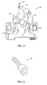
- the lateral surface 112 includes an aperture 124 therein, and an actuator slot 126 is exposed through the surface 112 so that the lever arm 118 can be remotely actuated with a mating actuator 128 ( Figure 14 ) in the manner described further below.
- the bottom surface 108 of the body 104 in the illustrated example is formed with a DIN rail slot 130 to facilitate mounting of the fuseholder assembly 102 for use.
- First and second fuse clips 132 and 134 are mounted stationary to the body 104 within the receptacle 116.
- the respective first and second fuse clips 132, 134 engage corresponding first and second conductive terminal elements 136, 138 ( Figures 5 and 6 ) of the fuse 120 when the fuse 120 is inserted into or received by the lever arm 118 and the lever arm 118 is in the closed position.
- the lever arm 118 is moved relative to the body 104 to the opened position, the first and second fuse clips 132, 134 are disengaged from the first and second conductive terminal element 136, 138.
- a line side connection terminal 140 is mechanically and electrically connected to the fuse clip 132, and a load side connection terminal 142 is mechanically and electrically connected to the second fuse clip 134.
- the line side connection terminal 140 is a panelboard clip and the load side terminal 142 is a wire lug terminal. It is appreciated, however, that a variety of alternative terminal structure is known in the art and could likewise be utilized in other embodiments.
- the line and load side connection terminals 140, 142 each respectively define a non-switchable current path to one of the first and second fuse clips 132, 134.
- one or more switching contacts could be associated with one of the line or load side connection terminals 140, 142 to provide a switchable current path through the fuse 120.
- Exemplary switching elements and arrangements are described in the applications referenced above and may be utilized in such an embodiment. Alternatively, other switching arrangements could be likewise be utilized.
- the panelboard clip 140 extends from the bottom surface 108 ( Figure 2 ) of the fuse holder body 104.
- the panelboard clip 140 may include, as shown in Figures 3 and 4 , a first portion 144 extending substantially perpendicularly to the bottom surface 108 of the body 104, and a second portion 146 extending substantially parallel to the bottom surface 108.
- the first portion 144 of the panelboard clip 140 may extend through and project from the bottom surface 108, thereby spacing the second 146 portion from the bottom surface 108. Because of this spacing, the fuseholder assembly 102 attaching the assembly 102 to the panelboard 100 ( Figure 1 ), or alternatively removing the assembly 102 from the panelboard 100, is simplified. Certain difficulties in installing or removing the fuse holder assembly 102, that are common to conventional fuse holders, are therefore avoided.
- the panelboard clip 140 is fabricated as an integral piece including the fuse clip 132 and the first and second portions 144 and 146.
- the panelboard clip 430 may be formed and shaped in a known manner using a suitable conductive material.
- the line and load side terminals 140, 142 and the fuse clips 132, 134 may be configured such that the assembly 102 may conform to accepted standards in the industry concerning their electrical ratings and other factors. Such standards include, but are not necessarily limited to UL and IEC standards familiar to those in the industry.
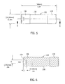
- FIG 5 is a side view and Figure 6 is a sectional view of the exemplary fuse 120 for the fuse holder assembly 120 in the exemplary embodiment shown.
- the fuse 120 includes a generally cylindrical fuse body 150 and conductive terminal elements 136, 138 attached to the opposing ends of the body 150.
- the body 150 may be fabricated from a suitable nonconductive material known in the art according to known processes.
- the terminal elements 136, 138 may be provided in the form of conductive ferrules as shown. The ferrules may be attached to the body 150 in any known manner.
- One or more fusible links or elements (not shown), or a fuse element assembly, is contained within the body 150 and connected between the fuse terminal elements 136, 138 so that when electrical current through the fuse 120 exceeds a predetermined limit, the fusible elements melt and open the circuit path through the fuse 120.
- the fusible element or elements that extend between the fuse terminals 136, 138 provided in the form of conductive ferrules as shown.
- the ferrules may be attached to the body 150 in any known manner.
- One or more fusible links or elements (not shown), or a fuse element assembly, is contained within the body 150 and connected between the fuse terminal elements 136, 138 so that when electrical current through the fuse 120 exceeds a predetermined limit, the fusible elements melt and open the circuit path through the fuse 120.
- the fusible element or elements that extend between the fuse terminals 136, 138 define a conductive current path for current to flow between the fuse clips 132 ; 134, and in turn completes a circuit path between the line and load side terminals 140, 142 of the assembly 102.
- the fusible element or elements operate in response to specified current conditions, however, no current is conducted between the fuse terminal elements 136, 138 and the line side terminal 146 becomes electrically isolated from the load side terminal 142. The fuse 120 must then be replaced to restore operation of the circuitry.
- the fuse 120 may be a photovoltaic fuse attachable to the panelboard 100 as part of a power distribution system in a solar powered electrical network.
- the fuse 120 may more specifically be a UL248-xx or IEC 60269-2-1 photovoltaic fuse having an operating voltage of about 1000Vdc, an amperage rating of about 1A to about 32A, and an interrupting rating of about 33kA.
- the fuse terminal element 136 includes an inwardly extending indention or depression 152 arranged on an axial centerline of the fuse 120.
- the depression 152 extends centrally on an end face 154 of the terminal element 136, and in one example, the depression 152 is a substantially cylindrical cavity having a length L of about 0.1 inches or 3.18 mm and a diameter D of about 0.2 inches or 3.81 mm.
- the stub 158 When the fuse 120 is inserted into the sleeve 155, the stub 158 may be received in the depression 152 in the fuse terminal element 136 and the end face 154 ( Figure 6 ) of the fuse terminal element 158 may be positioned in abutting contact with the abutment surface 156 of the sleeve 155 as shown in Figure 7 .
- the axial length of the sleeve 155 is about the same as the axial length of the fuse 120 so that the lever arm 118 can be moved to the closed position.
- the lever arm 118 in the illustrated embodiment is an integrally formed or single piece element including the sleeve 155, the actuator slot 126, and other features described herein.
- the lever arm 118 may be fabricated from plastic according to known techniques.
- the lever arm 118 includes generally opposed first and second ends 160 and 162.
- the end 160 defines the finger grip 122 and the open face of the sleeve 155.
- the end 162 is rotatably mounted to the fuse holder body 104 proximate the top surface 106 ( Figure 2 ) via the projecting actuator slot 156 formed in the end 162.
- the actuator slot 156 is situated in and exposed through the aperture 214 ( Figure 2 ) in the side surface 112.
- the lever arm 118 is accordingly pivotal about the end 162 such that the end 160 is selectively positionable to place the lever arm 118 in the open position and the closed position relative to the fuse holder body 104 as described above.
- the open position provides access to insert or remove the 120 fuse from the lever arm 118 and the closed position prevents access to the fuse 120 within the fuse holder body 104.
- a degree of safety is therefore provided that some conventional fuse holders do not provide.
- the lever arm 118 may be configured with an audible click feature so that a user can know if the arm 118 is completely closed.
- an audible click feature can be implemented in a variety of ways and is believed to be within the purview of those in the art.
- Figure 9 illustrates the lever arm 118 in the open position, but with an improper fuse received in the sleeve 155.
- the lever arm 118 is shown in Figure 9 with a Class CC fuse 190 that, instead of including the depression 152 ( Figure 6 ) in one of its terminal elements, actually includes a projection 192.
- the stub 158 interferes with the abutting terminal element at one end of the fuse 190 because the fuse does not include the depression 152, and the projection 192 extends beyond the sleeve 155 at the other end. As a result, the fuse 190 cannot be completely received in the sleeve 155.
- the projection 192 of the fuse 190 consequently interferes with the body 104 and frustrates any attempt to move the lever arm 118 to the closed position. As such, it can be practically assured that a user cannot mistakenly replace the proper fuse 120 with the improper fuse 190 and still complete an electrical connection through the assembly 102.
- Figure 10 illustrates the lever arm 118 in the open position, but with another improper fuse received in the sleeve 155.
- the lever arm 118 shown in Figure 10 is shown with fuse 200 such as a UL Supplemental fuse or IEC 10x38 fuse that can be placed in the sleeve 155, but because the fuse 200 does not include the depression 152 ( Figure 6 ) of the proper fuse 120, the stub 158 interferes with the abutting terminal element when the fuse 200 is inserted into the sleeve 155. Because of this interference, the fuse 200 cannot be completely received in the sleeve 155 and the portion of the fuse 200 at the end 160 projects from the sleeve 155.
- fuse 200 such as a UL Supplemental fuse or IEC 10x38 fuse that can be placed in the sleeve 155, but because the fuse 200 does not include the depression 152 ( Figure 6 ) of the proper fuse 120, the stub 158 interferes with the abutting terminal element when the fuse 200 is
- the projecting portion of the fuse 200 interferes with the body 104 and frustrates any attempt to move the lever arm 118 to the closed position. As such, it can be practically assured that a user cannot mistakenly replace the proper fuse 120 with the improper fuse 200 and still complete an electrical connection through the assembly 102.
- Figure 11 illustrates the lever arm 118 in the open position wherein fuses can be inserted or removed from the sleeve 155, and also showing a shank lock opening 210 formed just below the sleeve 155 at the end 160 of the lever arm 118.
- the opening 210 may receive the shank of a padlock, for example, and the assembly 102 may accordingly be locked with the lever arm 118 in the open position while the load side circuitry or components are serviced.
- the lever arm 118 can again be closed and the circuit completed through the fuse.
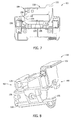
- Figure 12 illustrates a monitoring accessory 220 for the fuse holder 102.
- the accessory 220 is provided as a status module that is separately provided from the fuse holder assembly 202, and is configured to transmit a signal to a remote device when the fuse 120 operates to open a current path between the first and second fuse clips 132, 134 as described above.
- the accessory 220 includes a body 222 having sensors therein, and external wire conductors 224a, 224b, 224c each configured for connection in parallel to one of the fuses 120.
- the line and load side terminals 142 ( Figure 13 ) may be dual wire lug terminals that can each accept one of the conductor wires 224 ( Figure 14 ) for monitoring purposes, and one or more line side or load side connecting wires 226.
- the sensors in the housing, via the wires 224, are connected in parallel with the fuse 120 in the assembly 102 and may monitor voltage conditions, for example, across the fuse. When the fusible element operates and the fuse opens, the voltage drop is detected and a signal may be sent from the accessory 220 to a remote location to indicate the open fuse.
- the accessory 220 therefore is capable of monitoring three different modular fuse holder assemblies 102, and hence can independently monitor three different fuses 120 associated with the assemblies 102.
- the accessory 220 may be mounted to the panelboard 100 ( Figure 1 ) alongside the fuse holder assemblies 102 or may be used with fuse holder assemblies 102 apart from the panelboard 100.
- the actuator 128 (also shown in Figure 14 ) may be attached to and extend from the accessory 220 such that the accessory 220 can not only monitor the fuses in fuse holder assemblies 102, but also drive the lever arms 118 in the assembly 102 to the opened or closed positions. Proactive management of the power distribution system is therefore possible as the pivot arms 118 can be opened or closed from remote locations in response to operating conditions and disturbances, or to facilitate maintenance of the system.
- the actuator 128 When the actuator 128 is coupled to the actuator slot 126 ( Figure 2 ), rotation of the actuator 128 causes rotation of the actuator slot 126, and the lever arm 118 is accordingly opened or closed.
- Reset features may also be included in the accessory 220 so that the lever arm 118 can be manually opened without triggering the accessory 220 to signal an opened fuse condition to a remote location.
- An embodiment of a fuse holder assembly including: a nonconductive fuse holder body defining a fuse receptacle, the fuse holder body including a top surface and a side surface including an aperture; a lever arm adapted to receive and retain a cylindrical fuse having first and second conductive terminal elements, the lever arm including opposing first and second ends, the first end being rotatably mounted to the fuse holder body proximate the top surface and a portion of the first end being exposed and accessible through the aperture in the side surface, the lever arm being pivotal about the first end such that the second end is selectively positionable between an open position and a closed position relative to the fuse holder body, the open position providing access to insert or remove the cylindrical fuse from the lever arm and the closed position preventing access to the cylindrical fuse; first and second fuse clips mounted to said body, wherein the respective first and second fuse clips engage the first and second conductive terminal elements when the cylindrical fuse is received therein and the lever arm is in the closed position, and wherein the first and second fuse clips are disengaged from the first
- one of the line and load side connection terminals may be a panelboard clip extending from the fuse holder body.
- the fuse holder body may include a bottom surface opposite the top surface, and the panelboard clip may include a first portion extending substantially perpendicularly to the bottom surface and a second portion extending substantially parallel to the bottom surface. The first portion of the fuse clip may extend through and project from the bottom surface, thereby spacing the second portion from the bottom surface.
- the panelboard clip may be integrally formed with one of the first and second fuse clips.
- the fuse holder assembly may further include a panelboard, with the panelboard clip attachable to the panelboard.
- the lever arm may be configured to reject an incompatible fuse, including a UL Supplemental fuse, a class CC fuse, and an IEC 10x38 fuse.
- the lever arm may define an axial sleeve configured to receive the fuse, with the sleeve including an abutment surface for the cylindrical fuse and a fuse rejection stub projecting therefrom.
- the stub may be substantially aligned with a longitudinal axis of the cylindrical fuse when the fuse is received in the sleeve.
- One of the first and second conductive terminal elements of the cylindrical fuse may include an indentation, with the stub being received in the indentation.
- the fuse may be a photovoltaic fuse.
- a portion of the first end of the lever arm may define an actuator slot, with the actuator slot being exposed and accessible through the aperture in the side surface.
- the lever arm may optionally define a shank lock opening at the second end.
- a status module may optionally be separately provided from the nonconductive body and configured to transmit a signal to a remote device when the cylindrical fuse operates to open a current path between the first and second fuse clips.
- the status module may be configured to simultaneously monitor multiple cylindrical fuses.
- the status module may include an actuator coupled to an actuator slot of the fuse holder assembly, whereby when the actuator slot is rotated as the lever arm is opened, the actuator is also rotated and causes the status module to be reset.
- At least one of the line and load side connection terminals may optionally include a dual wire box lug terminal.
- An audible tactile click may be associated with one of the opened and closed positions of the lever arm.
- a height of the fuse holder may be less than about 72 mm.
- a width of the fuse holder may be about 17.5 mm or less.
- a panelboard When using a panelboard clip, a panelboard may also be provided, the clip being attachable to the panelboard.
- the lever arm may define a shank lock opening at the second end.
- the assembly may further comprise a status module separately provided from the nonconductive body and configured to transmit a signal to a remote device when the cylindrical fuse operates to open a current path between the first and second fuse clips.
- the status module may be configured to simultaneously monitor multiple cylindrical fuses.
- the portion of the first end being exposed and accessible through the aperture in the side surface may include an actuator slot, and that the status module may include an actuator coupled to the actuator slot, whereby when the actuator slot is rotated as the lever arm is opened, the actuator is also rotated and causes the status module to be reset.
- At least one of the line and load side connection terminals may comprise a dual wire box lug terminal.
- An audible tactile click may be associated with one of the opened and closed positions.
Landscapes
- Fuses (AREA)
- Regulation Of General Use Transformers (AREA)
Applications Claiming Priority (1)
| Application Number | Priority Date | Filing Date | Title |
|---|---|---|---|
| US12/875,273 US8310333B2 (en) | 2010-09-03 | 2010-09-03 | Modular fuse holder |
Publications (2)
| Publication Number | Publication Date |
|---|---|
| EP2426687A2 true EP2426687A2 (de) | 2012-03-07 |
| EP2426687A3 EP2426687A3 (de) | 2012-08-29 |
Family
ID=44785320
Family Applications (1)
| Application Number | Title | Priority Date | Filing Date |
|---|---|---|---|
| EP11179904A Withdrawn EP2426687A3 (de) | 2010-09-03 | 2011-09-02 | Modularer Sicherungshalter |
Country Status (2)
| Country | Link |
|---|---|
| US (1) | US8310333B2 (de) |
| EP (1) | EP2426687A3 (de) |
Cited By (2)
| Publication number | Priority date | Publication date | Assignee | Title |
|---|---|---|---|---|
| EP3410453A1 (de) * | 2017-05-31 | 2018-12-05 | TE Connectivity Corporation | Sicherungsplattenmodul mit beweglichem sicherungshalter |
| EP4052968A1 (de) * | 2021-03-01 | 2022-09-07 | Aptiv Technologies Limited | Hochspannungsleistungsverteiler |
Families Citing this family (23)
| Publication number | Priority date | Publication date | Assignee | Title |
|---|---|---|---|---|
| US11804350B2 (en) | 2004-09-13 | 2023-10-31 | Eaton Intelligent Power Limited | Fusible switching disconnect modules and devices with tripping coil |
| US11404233B2 (en) | 2004-09-13 | 2022-08-02 | Eaton Intelligent Power Limited | Fusible switching disconnect modules and devices with tripping coil |
| US11335528B2 (en) * | 2011-01-19 | 2022-05-17 | Eaton Intelligent Power Limited | Fusible switching disconnect modules and devices with electromagnetic coil and trip mechanism |
| EP3098825B1 (de) | 2011-01-19 | 2021-04-07 | Eaton Intelligent Power Limited | Schmelzschalttrennmodule und vorrichtungen mit inline-stromdetektion |
| ES2527593T3 (es) * | 2011-01-19 | 2015-01-27 | Cooper Technologies Company | Módulos y dispositivos seccionadores interruptores fusibles controlados electrónicamente |
| CN102122594B (zh) * | 2011-03-11 | 2013-05-01 | 上海诺雅克电气有限公司 | 熔断器 |
| US9419494B2 (en) * | 2011-05-11 | 2016-08-16 | Siemens Industry, Inc. | Induction machine power connection box including power supply for auxiliary devices including auxiliary cooling fans |
| US8419475B2 (en) * | 2011-07-19 | 2013-04-16 | Cooper Technologies Company | Modular open fuseholder with multi-stage positionable cover |
| DE102011052198A1 (de) * | 2011-07-27 | 2013-01-31 | Phoenix Contact Gmbh & Co. Kg | Sicherungsklemme |
| DE102011119173B4 (de) * | 2011-11-23 | 2013-11-28 | Phoenix Contact Gmbh & Co. Kg | Generatoranschlusskasten fürPhotovoltaikanlagen und Eingangsmodule |
| USD718255S1 (en) * | 2012-06-01 | 2014-11-25 | Df, S.A. | Fuse holder base |
| US9170293B2 (en) | 2012-06-07 | 2015-10-27 | Cooper Technologies Company | Power line indicator accessory for fusible circuit protection device array |
| US9214310B2 (en) * | 2012-10-29 | 2015-12-15 | Tyco Electronics Corporation | Service disconnect assembly |
| US9136083B2 (en) | 2013-03-15 | 2015-09-15 | Regal Beloit America, Inc. | Enclosed bus bar fuse holder |
| US10008347B1 (en) * | 2013-08-08 | 2018-06-26 | Palle Kohring Weinreich | Electrical switch with built in fuse improvement |
| US9613776B2 (en) * | 2014-08-19 | 2017-04-04 | Regal Beloit America, Inc. | Fuse holder and associated method |
| US10249465B2 (en) | 2016-06-15 | 2019-04-02 | Regal Beloit America, Inc. | Fuse holder, carrier and associated method |
| US10068737B2 (en) | 2016-06-15 | 2018-09-04 | Regal Beloit America, Inc. | Fuse holder and carrier |
| DE102018208725A1 (de) * | 2018-06-04 | 2019-12-05 | Phoenix Contact Gmbh & Co. Kg | Überspannungsschutzgeräte-Ensemble |
| EP3608934A1 (de) * | 2018-08-07 | 2020-02-12 | Gorlan Team, S.L.U. | Sicherungs-schaltmodul |
| US11302506B1 (en) * | 2020-04-20 | 2022-04-12 | Norberg-IES, LLC | High voltage fuse adapter system and method |
| US11139136B1 (en) | 2020-05-30 | 2021-10-05 | Regal Beloit America, Inc. | Fuse holder with busbar clamp |
| US11362468B1 (en) * | 2020-12-04 | 2022-06-14 | DIAC Holdings LLC | Coupling device for short-circuit protection |
Citations (1)
| Publication number | Priority date | Publication date | Assignee | Title |
|---|---|---|---|---|
| US7576630B2 (en) | 2004-09-13 | 2009-08-18 | Cooper Technologies Company | Fusible switching disconnect modules and devices |
Family Cites Families (29)
| Publication number | Priority date | Publication date | Assignee | Title |
|---|---|---|---|---|
| US3194926A (en) * | 1961-05-31 | 1965-07-13 | Buchanan Electrical Prod Corp | Fuse assembly having pivotally and slidably mounted insulating member in one of its fuse clips |
| US3436695A (en) * | 1965-02-15 | 1969-04-01 | Square D Co | Electric circuit breaker with shunt trip coil |
| FR1467125A (fr) * | 1965-12-13 | 1967-01-27 | Telemecanique Electrique | Sectionneur rotatif à cartouche fusible |
| US3599135A (en) * | 1970-01-12 | 1971-08-10 | Ite Imperial Corp | Circuit protection arrangement including coordinated operation of a circuit breaker and a current limiting fuse |
| US3614697A (en) * | 1970-07-20 | 1971-10-19 | Square D Co | Molded case electric circuit breaker with fuse and indicator lamp |
| US3820046A (en) * | 1973-10-15 | 1974-06-25 | Square D Co | Auxiliary switch for molded-case circuit breaker |
| US4178061A (en) * | 1977-02-15 | 1979-12-11 | Ahroni Joseph M | Fused electrical plug |
| US4299435A (en) * | 1979-12-31 | 1981-11-10 | Duracell International Inc. | Fuse receptacle |
| US4514723A (en) | 1983-04-14 | 1985-04-30 | Leal David T | Method and apparatus for depicting inoperative electrical fuses |
| US5076118A (en) * | 1990-09-18 | 1991-12-31 | Siemens Energy & Automation, Inc. | Fuse insertion or removal tool |
| US5295850A (en) | 1993-04-19 | 1994-03-22 | Challenger Electrical Materials, Inc. | Fuse holder with fuse release |
| US5616054A (en) * | 1995-10-30 | 1997-04-01 | Gould Electronics Inc. | Fuse holder |
| DE69627973T2 (de) * | 1995-12-20 | 2003-11-27 | Legrand Snc, Limoges | Hilfsschalter für Ausschalter und entsprechender Ausschalter |
| US6157287A (en) * | 1999-03-03 | 2000-12-05 | Cooper Technologies Company | Touch safe fuse module and holder |
| DE50006510D1 (de) * | 1999-07-22 | 2004-06-24 | Klaus Bruchmann | Schaltersicherungseinheit mit halterverriegelung |
| CN1203505C (zh) | 1999-11-23 | 2005-05-25 | 克劳斯·布鲁赫曼 | 具有保险绝缘座和保险状态报警器的开关保险单元 |
| EP1134762B1 (de) * | 2000-03-16 | 2004-05-06 | Hubert Laurenz Naimer | Schalter |
| US6696969B2 (en) | 2000-06-30 | 2004-02-24 | Cooper Technologies, Inc. | Compact fused disconnect switch |
| US6650222B2 (en) * | 2000-12-07 | 2003-11-18 | Cooper Technologies Company | Modular fuseholder |
| US6759939B2 (en) * | 2002-04-26 | 2004-07-06 | General Electric Company | Fuse holder assembly |
| US6794979B2 (en) * | 2002-04-26 | 2004-09-21 | General Electric Company | Fuse holder assembly |
| US7116550B2 (en) | 2003-10-30 | 2006-10-03 | Server Technology, Inc. | Electrical circuit apparatus with fuse access section |
| DE102004031110B4 (de) * | 2004-06-28 | 2008-02-14 | Wöhner GmbH & Co. KG Elektrotechnische Systeme | Sicherungsschalter |
| US7561017B2 (en) * | 2004-09-13 | 2009-07-14 | Cooper Technologies Company | Fusible switching disconnect modules and devices |
| US7855873B2 (en) | 2004-09-13 | 2010-12-21 | Cooper Technologies Company | Panelboard for fusible switching disconnect devices |
| US7447002B2 (en) * | 2006-01-11 | 2008-11-04 | Server Technology, Inc. | Fuse module with movable fuse holder for fused electrical device |
| US7561018B2 (en) * | 2006-02-09 | 2009-07-14 | Wöhner GmbH & Co. KG | Fuse strip with lateral outgoing contacts and a lateral adapter module |
| DE102009017338B4 (de) * | 2009-04-14 | 2016-12-01 | Wöhner GmbH & Co. KG Elektrotechnische Systeme | Halter für Sicherungen |
| US8134828B2 (en) * | 2010-01-21 | 2012-03-13 | Cooper Technologies Company | Configurable deadfront fusible panelboard |
-
2010
- 2010-09-03 US US12/875,273 patent/US8310333B2/en active Active
-
2011
- 2011-09-02 EP EP11179904A patent/EP2426687A3/de not_active Withdrawn
Patent Citations (1)
| Publication number | Priority date | Publication date | Assignee | Title |
|---|---|---|---|---|
| US7576630B2 (en) | 2004-09-13 | 2009-08-18 | Cooper Technologies Company | Fusible switching disconnect modules and devices |
Cited By (4)
| Publication number | Priority date | Publication date | Assignee | Title |
|---|---|---|---|---|
| EP3410453A1 (de) * | 2017-05-31 | 2018-12-05 | TE Connectivity Corporation | Sicherungsplattenmodul mit beweglichem sicherungshalter |
| US10283309B2 (en) | 2017-05-31 | 2019-05-07 | Te Connectivity Corporation | Fuse panel module with a movable fuse holder |
| EP4052968A1 (de) * | 2021-03-01 | 2022-09-07 | Aptiv Technologies Limited | Hochspannungsleistungsverteiler |
| US11908653B2 (en) | 2021-03-01 | 2024-02-20 | Aptiv Technologies AG | High voltage power distributor |
Also Published As
| Publication number | Publication date |
|---|---|
| EP2426687A3 (de) | 2012-08-29 |
| US8310333B2 (en) | 2012-11-13 |
| US20120056708A1 (en) | 2012-03-08 |
Similar Documents
| Publication | Publication Date | Title |
|---|---|---|
| US8310333B2 (en) | Modular fuse holder | |
| US7855873B2 (en) | Panelboard for fusible switching disconnect devices | |
| US7576630B2 (en) | Fusible switching disconnect modules and devices | |
| CA2352435C (en) | Fused disconnect switch | |
| US8715008B2 (en) | Modular open fuse holder with multi-stage positionable cover | |
| US7561017B2 (en) | Fusible switching disconnect modules and devices | |
| US9543083B2 (en) | Fusible switching disconnect modules and devices with in-line current detection | |
| US9224548B2 (en) | Disconnect switch including fusible switching disconnect modules | |
| US6998954B2 (en) | Fused electrical disconnect device | |
| US11217413B2 (en) | Electronically controlled fusible switching disconnect modules and devices | |
| US8134828B2 (en) | Configurable deadfront fusible panelboard | |
| US10665413B2 (en) | Fusible switch disconnect device for DC electrical power system | |
| US12191099B2 (en) | Electronically controlled fusible switching disconnect modules and devices | |
| US11355299B2 (en) | Fusible switching disconnect modules and devices with in-line current detection | |
| CN101354988A (zh) | 可与断路器连接的剩余电流装置 | |
| EP1880404B1 (de) | Modular-indikations-sicherungshalter | |
| US9170293B2 (en) | Power line indicator accessory for fusible circuit protection device array | |
| WO2024041855A1 (de) | Modular gebildetes, mehrpoliges reiheneinbaugerät | |
| HK1162739A (en) | Fused disconnect switch with terminal opening cover |
Legal Events
| Date | Code | Title | Description |
|---|---|---|---|
| AK | Designated contracting states |
Kind code of ref document: A2 Designated state(s): AL AT BE BG CH CY CZ DE DK EE ES FI FR GB GR HR HU IE IS IT LI LT LU LV MC MK MT NL NO PL PT RO RS SE SI SK SM TR |
|
| AX | Request for extension of the european patent |
Extension state: BA ME |
|
| PUAI | Public reference made under article 153(3) epc to a published international application that has entered the european phase |
Free format text: ORIGINAL CODE: 0009012 |
|
| PUAL | Search report despatched |
Free format text: ORIGINAL CODE: 0009013 |
|
| AK | Designated contracting states |
Kind code of ref document: A3 Designated state(s): AL AT BE BG CH CY CZ DE DK EE ES FI FR GB GR HR HU IE IS IT LI LT LU LV MC MK MT NL NO PL PT RO RS SE SI SK SM TR |
|
| AX | Request for extension of the european patent |
Extension state: BA ME |
|
| RIC1 | Information provided on ipc code assigned before grant |
Ipc: H01H 9/10 20060101AFI20120725BHEP Ipc: H01H 85/54 20060101ALI20120725BHEP |
|
| STAA | Information on the status of an ep patent application or granted ep patent |
Free format text: STATUS: THE APPLICATION IS DEEMED TO BE WITHDRAWN |
|
| 18D | Application deemed to be withdrawn |
Effective date: 20130301 |