EP3410453A1 - Sicherungsplattenmodul mit beweglichem sicherungshalter - Google Patents
Sicherungsplattenmodul mit beweglichem sicherungshalter Download PDFInfo
- Publication number
- EP3410453A1 EP3410453A1 EP18174193.5A EP18174193A EP3410453A1 EP 3410453 A1 EP3410453 A1 EP 3410453A1 EP 18174193 A EP18174193 A EP 18174193A EP 3410453 A1 EP3410453 A1 EP 3410453A1
- Authority
- EP
- European Patent Office
- Prior art keywords
- fuse
- contact
- movable
- holder
- panel
- Prior art date
- Legal status (The legal status is an assumption and is not a legal conclusion. Google has not performed a legal analysis and makes no representation as to the accuracy of the status listed.)
- Granted
Links
Images



Classifications
-
- H—ELECTRICITY
- H01—ELECTRIC ELEMENTS
- H01H—ELECTRIC SWITCHES; RELAYS; SELECTORS; EMERGENCY PROTECTIVE DEVICES
- H01H85/00—Protective devices in which the current flows through a part of fusible material and this current is interrupted by displacement of the fusible material when this current becomes excessive
- H01H85/02—Details
- H01H85/20—Bases for supporting the fuse; Separate parts thereof
- H01H85/2015—Bases for supporting the fuse; Separate parts thereof for plug-in type fuses
-
- H—ELECTRICITY
- H01—ELECTRIC ELEMENTS
- H01H—ELECTRIC SWITCHES; RELAYS; SELECTORS; EMERGENCY PROTECTIVE DEVICES
- H01H85/00—Protective devices in which the current flows through a part of fusible material and this current is interrupted by displacement of the fusible material when this current becomes excessive
- H01H85/02—Details
- H01H85/22—Intermediate or auxiliary parts for carrying, holding, or retaining fuse, co-operating with base or fixed holder, and removable therefrom for renewing the fuse
-
- H—ELECTRICITY
- H01—ELECTRIC ELEMENTS
- H01H—ELECTRIC SWITCHES; RELAYS; SELECTORS; EMERGENCY PROTECTIVE DEVICES
- H01H21/00—Switches operated by an operating part in the form of a pivotable member acted upon directly by a solid body, e.g. by a hand
- H01H21/02—Details
- H01H21/16—Adaptation for built-in fuse
-
- H—ELECTRICITY
- H01—ELECTRIC ELEMENTS
- H01H—ELECTRIC SWITCHES; RELAYS; SELECTORS; EMERGENCY PROTECTIVE DEVICES
- H01H85/00—Protective devices in which the current flows through a part of fusible material and this current is interrupted by displacement of the fusible material when this current becomes excessive
- H01H85/02—Details
- H01H85/20—Bases for supporting the fuse; Separate parts thereof
- H01H85/2045—Mounting means or insulating parts of the base, e.g. covers, casings
-
- H—ELECTRICITY
- H01—ELECTRIC ELEMENTS
- H01H—ELECTRIC SWITCHES; RELAYS; SELECTORS; EMERGENCY PROTECTIVE DEVICES
- H01H85/00—Protective devices in which the current flows through a part of fusible material and this current is interrupted by displacement of the fusible material when this current becomes excessive
- H01H85/02—Details
- H01H85/47—Means for cooling
-
- H—ELECTRICITY
- H01—ELECTRIC ELEMENTS
- H01H—ELECTRIC SWITCHES; RELAYS; SELECTORS; EMERGENCY PROTECTIVE DEVICES
- H01H85/00—Protective devices in which the current flows through a part of fusible material and this current is interrupted by displacement of the fusible material when this current becomes excessive
- H01H85/54—Protective devices wherein the fuse is carried, held, or retained by an intermediate or auxiliary part removable from the base, or used as sectionalisers
- H01H85/547—Protective devices wherein the fuse is carried, held, or retained by an intermediate or auxiliary part removable from the base, or used as sectionalisers with sliding fuse carrier
-
- H—ELECTRICITY
- H01—ELECTRIC ELEMENTS
- H01H—ELECTRIC SWITCHES; RELAYS; SELECTORS; EMERGENCY PROTECTIVE DEVICES
- H01H9/00—Details of switching devices, not covered by groups H01H1/00 - H01H7/00
- H01H9/10—Adaptation for built-in fuses
-
- H—ELECTRICITY
- H01—ELECTRIC ELEMENTS
- H01R—ELECTRICALLY-CONDUCTIVE CONNECTIONS; STRUCTURAL ASSOCIATIONS OF A PLURALITY OF MUTUALLY-INSULATED ELECTRICAL CONNECTING ELEMENTS; COUPLING DEVICES; CURRENT COLLECTORS
- H01R13/00—Details of coupling devices of the kinds covered by groups H01R12/70 or H01R24/00 - H01R33/00
- H01R13/62—Means for facilitating engagement or disengagement of coupling parts or for holding them in engagement
- H01R13/629—Additional means for facilitating engagement or disengagement of coupling parts, e.g. aligning or guiding means, levers, gas pressure electrical locking indicators, manufacturing tolerances
- H01R13/62905—Additional means for facilitating engagement or disengagement of coupling parts, e.g. aligning or guiding means, levers, gas pressure electrical locking indicators, manufacturing tolerances comprising a camming member
-
- H—ELECTRICITY
- H01—ELECTRIC ELEMENTS
- H01R—ELECTRICALLY-CONDUCTIVE CONNECTIONS; STRUCTURAL ASSOCIATIONS OF A PLURALITY OF MUTUALLY-INSULATED ELECTRICAL CONNECTING ELEMENTS; COUPLING DEVICES; CURRENT COLLECTORS
- H01R13/00—Details of coupling devices of the kinds covered by groups H01R12/70 or H01R24/00 - H01R33/00
- H01R13/66—Structural association with built-in electrical component
- H01R13/68—Structural association with built-in electrical component with built-in fuse
-
- H—ELECTRICITY
- H01—ELECTRIC ELEMENTS
- H01H—ELECTRIC SWITCHES; RELAYS; SELECTORS; EMERGENCY PROTECTIVE DEVICES
- H01H85/00—Protective devices in which the current flows through a part of fusible material and this current is interrupted by displacement of the fusible material when this current becomes excessive
- H01H85/02—Details
- H01H85/20—Bases for supporting the fuse; Separate parts thereof
- H01H2085/209—Modular assembly of fuses or holders, e.g. side by side; combination of a plurality of identical fuse units
-
- H—ELECTRICITY
- H01—ELECTRIC ELEMENTS
- H01H—ELECTRIC SWITCHES; RELAYS; SELECTORS; EMERGENCY PROTECTIVE DEVICES
- H01H85/00—Protective devices in which the current flows through a part of fusible material and this current is interrupted by displacement of the fusible material when this current becomes excessive
- H01H85/54—Protective devices wherein the fuse is carried, held, or retained by an intermediate or auxiliary part removable from the base, or used as sectionalisers
-
- H—ELECTRICITY
- H01—ELECTRIC ELEMENTS
- H01H—ELECTRIC SWITCHES; RELAYS; SELECTORS; EMERGENCY PROTECTIVE DEVICES
- H01H9/00—Details of switching devices, not covered by groups H01H1/00 - H01H7/00
- H01H9/10—Adaptation for built-in fuses
- H01H9/104—Adaptation for built-in fuses with interlocking mechanism between switch and fuse
-
- H—ELECTRICITY
- H01—ELECTRIC ELEMENTS
- H01R—ELECTRICALLY-CONDUCTIVE CONNECTIONS; STRUCTURAL ASSOCIATIONS OF A PLURALITY OF MUTUALLY-INSULATED ELECTRICAL CONNECTING ELEMENTS; COUPLING DEVICES; CURRENT COLLECTORS
- H01R13/00—Details of coupling devices of the kinds covered by groups H01R12/70 or H01R24/00 - H01R33/00
- H01R13/66—Structural association with built-in electrical component
- H01R13/68—Structural association with built-in electrical component with built-in fuse
- H01R13/684—Structural association with built-in electrical component with built-in fuse the fuse being removable
- H01R13/688—Structural association with built-in electrical component with built-in fuse the fuse being removable with housing part adapted for accessing the fuse
-
- H—ELECTRICITY
- H01—ELECTRIC ELEMENTS
- H01R—ELECTRICALLY-CONDUCTIVE CONNECTIONS; STRUCTURAL ASSOCIATIONS OF A PLURALITY OF MUTUALLY-INSULATED ELECTRICAL CONNECTING ELEMENTS; COUPLING DEVICES; CURRENT COLLECTORS
- H01R13/00—Details of coupling devices of the kinds covered by groups H01R12/70 or H01R24/00 - H01R33/00
- H01R13/66—Structural association with built-in electrical component
- H01R13/70—Structural association with built-in electrical component with built-in switch
-
- H—ELECTRICITY
- H01—ELECTRIC ELEMENTS
- H01R—ELECTRICALLY-CONDUCTIVE CONNECTIONS; STRUCTURAL ASSOCIATIONS OF A PLURALITY OF MUTUALLY-INSULATED ELECTRICAL CONNECTING ELEMENTS; COUPLING DEVICES; CURRENT COLLECTORS
- H01R2103/00—Two poles
-
- H—ELECTRICITY
- H01—ELECTRIC ELEMENTS
- H01R—ELECTRICALLY-CONDUCTIVE CONNECTIONS; STRUCTURAL ASSOCIATIONS OF A PLURALITY OF MUTUALLY-INSULATED ELECTRICAL CONNECTING ELEMENTS; COUPLING DEVICES; CURRENT COLLECTORS
- H01R24/00—Two-part coupling devices, or either of their cooperating parts, characterised by their overall structure
- H01R24/66—Two-part coupling devices, or either of their cooperating parts, characterised by their overall structure with pins, blades or analogous contacts and secured to apparatus or structure, e.g. to a wall
- H01R24/70—Two-part coupling devices, or either of their cooperating parts, characterised by their overall structure with pins, blades or analogous contacts and secured to apparatus or structure, e.g. to a wall with additional earth or shield contacts
Definitions
- the present invention relates to a fuse panel module to allow access to one or more fuses. More particularly, the invention is directed to a fuse panel module having a movable fuse holder.
- Fuses are a common component found in many electrical devices.
- fuses are electrical safety components consisting of a wire or strip that melts and interrupts a circuit when the current passing through the fuse exceeds a particular amperage. Once a fuse is blown, i.e., the wire or strip melts, the fuse must be replaced to re-establish the circuit.
- Replacing blown fuses in fused electrical devices often requires disassembly of the electrical device and/or use of one or more hand-tools to access and retrieve a blown fuse. Accordingly, accessing and replacing a blown fuse can often be a difficult, cumbersome and time-consuming process.
- a fuse holder must tolerate high fuse temperature, conduct heat away from the fuse and fit in a housing. Metal contacts survive high temperatures while conducting heat away from the fuse.
- Axial fuse holders which minimize panel space by presenting the smallest profile of the fuses to the user, must make contact with the proximal end of the fuse after the housing accepts the distal end. This is presently done either by a movable proximal fuse contact, actuated by a part of the dielectric cover, or a fuse contact mounted on the cover that connects through an additional, separable contact to the housing circuit. Such axial fuse holders cannot tolerate much heat.
- the dielectric cover that actuates the fuse contact cannot tolerate high fuse temperatures, and its movable fuse contact cannot conduct much heat.
- the separable contact generates heat and restricts heat transmission from the fuse.
- Radial fuse holders present both ends of a fuse to fixed metal fuse contacts but occupy more panel space.
- the solution is provided by a fixed proximal fuse contact that is mounted in a housing of a fuse panel module and which is opened by a camming member while a distal end of the fuse passes through the proximal contact.
- the camming member releases the proximal fuse contact onto the proximal fuse head.
- a distal fuse contact mounted in the housing receives the distal fuse head.
- Both fuse contacts are permanently connected to the housing circuit, are metal and provide preload to maintain a stable fuse contact. This creates less heat and provides superior transmission of heat away from the fuses, with the minimal panel footprint of an axial fuse holder.
- An object is to provide a fixed proximal fuse contact that is mounted in a housing of a fuse panel module and which is opened by a camming member while a distal end of the fuse passes through the proximal contact.
- the camming member releases the proximal fuse contact onto the proximal fuse head.
- a distal fuse contact mounted in the housing receives the distal fuse head.
- Both fuse contacts are permanently connected to the housing circuit, are metal and provide preload to maintain a stable fuse contact. This creates less heat and provides superior transmission of heat away from the fuses, with the minimal panel footprint of an axial fuse holder.
- An embodiment is directed to a panel fuse module for use with one or more fuses.
- the panel fuse module includes a housing with a first fuse contact and a second fuse contact.
- the first fuse contact is resiliently deformable and is mounted on a post of the housing.
- the second fuse contact is mounted on the post of the housing and spaced from the first fuse contact.
- a movable fuse holder is provided which is moveable relative to the housing and relative to the first fuse contact.
- the movable holder is movable from a first position in which a portion of the movable fuse holder extends from the housing and one or more fuses may be inserted into the movable fuse holder without engaging the first fuse contact or the second fuse contact to a second position in which the movable fuse holder is inserted into the housing.
- a cam member is provided on the movable fuse holder. As the movable fuse holder is moved from the first position toward the second position, the cam member cooperates with the first fuse contact to move the first fuse contact from a less-stressed first position to a more-stressed second position to allow the respective fuse of the one or more fuses to be inserted into the housing without engaging the first fuse contact. As the movable fuse holder is moved into the second position, the cam member disengages the first fuse contact to allow the first fuse contact to move toward the less-stressed first position to allow the first fuse contact to be provided in mechanical and electrical engagement with the respective fuse of the one or more fuses.
- An embodiment is directed to a panel fuse module for use with one or more fuses.
- the panel fuse module includes a housing having a fixed post, a fixed rail and a fuse holder.
- the fuse holder is movable relative to the fixed post, and the fixed rail from a first position in which a respective fuse of the one or more fuses is positioned in the fuse holder to a second position in which the respective fuse and the fuse holder are inserted into the housing.
- a first fuse contact is mounted on the fixed post proximate the front of the housing.
- a second fuse is mounted on the fixed post spaced from the first fuse contact toward the rear of the housing.
- a cam member is provided on the movable fuse holder.
- the cam member cooperates with the first fuse contact to move the first fuse contact from a less-stressed first position to a more-stressed second position to allow the respective fuse to be inserted into the housing without engaging the first fuse contact.
- the cam member disengages the first fuse contact to allow the first fuse contact to move toward the less-stressed first position to allow the first fuse contact to be provided in mechanical and electrical engagement with the respective fuse of the one or more fuses.
- An embodiment is directed to a method of terminating a fuse in a fuse panel module, the fuse module having a first fuse contact and a second fuse contact.
- the method includes: inserting the fuse into a movable fuse holder of the fuse panel module; moving the movable fuse holder from a first position in which the fuse does not engage the first or second fuse contact to a second position in which the fuse is provided in mechanical and electrical engagement with the first and second fuse contacts; camming the first fuse contact to an open or resiliently deformed position as the movable portion is moved between the first position and the second position, the open position allowing the fuse to move relative first fuse contact without engaging the first fuse contact; and disengaging the first fuse contact from a cam of the movable fuse holder when the movable portion is moved to the second position, allowing the first fuse contact to resiliently move toward a less-stressed position, allowing the first fuse contact to be moved and retained in electrical and mechanical engagement with the fuse when the movable fuse holder is in the second position.
- an illustrative panel fuse module 10 includes a housing 12 with a cover 14.
- the panel fuse module 10 is configured to receive two fuses 15 thereon.
- the panel fuse module may be configured to receive one or more fuses therein.
- the housing 12 has a front wall 16 with an outwardly facing surface 18 and an inwardly facing surface 20.
- a switch 22 extends through the front wall 16 and has a rocker 24 which extends proximate the outward facing surface 18.
- a plug-receiving cavity 26 extends from the outwardly facing surface 18.
- the plug-receiving cavity 26 has contacts 28 which extend therein for making a mechanical and electrical connection with a mating plug (not shown).
- a fuse holder-receiving opening 29 extends through the front wall 16 and is dimensioned to receive a movable fuse holder 70 therein, as will be more fully described.
- Two posts 30 extend from the inwardly facing surface 20 of the front wall 16 in a direction away from the outwardly facing surface 18.
- the posts 30 are essentially mirror images of each other and are positioned on either side of the movable fuse holder-receiving opening 29.
- Each post 30 has an outer surface 32 ( FIG. 3 ) and a contoured inner surface 34 ( FIG. 3 ).
- Supports 36 may be provided to provide additional support and stabilization to the posts 30.
- a fixed guide rail 38 extends from the plug-receiving cavity 26 both outwardly toward the surface 18 and inwardly.
- the fixed guide rail 38 ( FIG. 1 ) is positioned and configured to cooperate with the movable fuse holder 70 to maintain the movable fuse holder 70 in proper position relative to the posts 30 and the housing 12.
- a first fuse contact 40 and a second fuse contact 42 are positioned on each post 30.
- the first fuse contacts 40 are fixed to the posts 30 proximate to the inwardly facing surface 20 of the front wall 16.
- the second fuse contacts 42 are spaced from the first fuse contacts 40 and are positioned proximate a distal end 44 of the posts 30.
- each of the first fuse contacts 40 has plate portion 48 with resilient fuse engagement contact arms 50 which extend from a top and bottom (as viewed in FIG. 7 ) of the plate portion 48.
- the resilient fuse engagement contact arms 50 that extend from the bottom of the plate portion 48 are essentially mirror images of the resilient fuse engagement contact arms 50 that extend from the top of the plate portion 48.
- Each resilient fuse engagement contact arm 50 has an arcuate shaped section 52 which is configured to engage a respective fuse 15.
- a cam engagement portion 54 is provided at the free end of each of the resilient fuse engagement contact arms 50.
- Lead-in portions 55 are provide at each end of the cam engagement portion 54 to facilitate the movement of the cam engagement portion 54 relative to the camming members.
- the plate portions 48, 49 are optional and are used if the fuse contacts 40, 42 are not bypassed by the wires 66, 68 from the switch 22 and contacts 28. When present, the plate portions 48, 49 are symmetrical to provide double-fusing.
- each wire termination portion 56 Positioned proximate the resilient fuse engagement contact arms 50 of each fuse contact 40 is a wire termination portion 56.
- the wire termination portion 56 has wire termination arms 58 which extend from a top and bottom (as viewed in FIG. 7 ) of the plate portion 48.
- the wire termination arms 58 that extend from the bottom of the plate portion 48 are essentially mirror images of the wire termination arms 58 that extend from the top of the plate portion 48.
- Each wire termination arm 58 has a wire receiving slot 60 which is configured as a wire engagement slot.
- the plate portions 48 have securing members 62 which are formed therein.
- the securing members 62 cooperate with the posts 30 to help retain and maintain the fuse contacts 40, 42 in position on the posts 30.
- the plate portions 48 have a relatively large surface area which allows for superior transmission of heat away from the fuses 15. The transmission of heat is also facilitated by the location of the plate portions 48 on the outer surface 32 of the posts 30, directly adjacent to the wall of the outer cover 14, where more air circulation is available to cool the plate portions 48.
- the plate portions 48 extends over the outer surface 32.
- the resilient fuse engagement contact arms 50 and the wire termination arms 58 extend from the plate portions over the posts 30 past the contoured inner surface 34 and into a movable fuse holder receiving passage which aligns with the movable fuse holder-receiving opening 29.
- each of the second fuse contacts 42 has plate portion 49 with resilient fuse engagement contact arms 51 which extend from a top and bottom (as viewed in FIG. 8 ) of the plate portion 49.
- the resilient fuse engagement contact arms 51 that extend from the bottom of the plate portion 49 are essentially mirror images of the resilient fuse engagement contact arms 51 that extend from the top of the plate portion 49.
- Each resilient fuse engagement contact arm 51 has an arcuate shaped section 53 which is configured to engage a respective fuse 15. Lead-in portions 65 are provide at the leading end of the arcuate shaped section 53 to help guide the end of the fuse 15 into engagement with the arcuate shaped section 53.
- each wire termination portion 57 Positioned proximate the resilient fuse engagement contact arms 51 of each fuse contact 42 is a wire termination portion 57.
- the wire termination portion 57 has wire termination arms 59 which extend from a top and bottom (as viewed in FIG. 8 ) of the plate portion 49.
- the wire termination arms 59 that extend from the bottom of the plate portion 49 are essentially mirror images of the wire termination arms 59 that extend from the top of the plate portion 49.
- Each wire termination arm 59 has a wire receiving slot 61 which is configured as a wire engagement slot.
- the plate portions 49 have securing members 63 which are formed therein.
- the securing members 63 cooperate with the posts 30 to help retain and maintain the fuse contacts 42 in position on the posts 30.
- the plate portions 49 have a relatively large surface area which allows for superior transmission of heat away from the fuses 15. The transmission of heat is also facilitated by the location of the plate portions 49 on the outer surface 32 of the posts 30, directly adjacent to the wall of the outer cover 14, where more air circulation is available to cool the plate portions 49.
- the plate portions 49 extends over the outer surface 32.
- the resilient fuse engagement contact arms 51 and the wire termination arms 59 extend from the plate portions over the posts 30 past the contoured inner surface 34 and into a movable fuse holder receiving passage which aligns with the movable fuse holder-receiving opening 29.
- Wires 66 extend from the switch 22 to the first fuse contacts 40.
- Wires 68 extend from the contacts 28 to the second fuse contacts 42.
- wires are shown, other methods and devices for making the electrical connection between the switch 22 and the first fuse contacts 40 and between the contacts 28 and the second fuse contacts 42 can be used, such as, for example, using stamped and formed metal leads.
- the movable fuse holder 70 has an end plate 72.
- the end plate 72 is provided to prevent the movable fuse holder 70 from being inserted too far into the housing 12, thereby preventing damage to the fuses 15 and the first and second fuse contacts 40, 42 as the movable fuse holder 70 is moved to the second position.
- the end plate 72 also cooperates with the mating plug when the mating plug in inserted into the plug-receiving cavity 26 to prevent the movable fuse holder 70 from being moved from the second position when the mating plug is in electrical engagement with the panel fuse module 10.
- the end plate 72 also prevents the user from contact with live parts of the panel fuse module 10.
- Camming members 74 are provided on the movable fuse holder 70 and extend proximate to and are essentially parallel to a longitudinal axis of the movable fuse holder 70. As best shown in FIG. 9 , each of the camming members 74 have a tip section 76, a raised section 78 and a release section 80.
- the height of the raised section 78 is greater than the height of the tip section 76 or the release section 80.
- a ramp 82 is provided between the raised section 78 and the tip section 76.
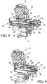
- the raised section 78 engages the cam engagement portions 54 of a first fuse contact 40 when the movable fuse holder 70 is moved from the first position toward the second position, as shown in FIG. 5 . In this position, the resilient fuse engagement contact arms 50 are more stressed or resiliently deformed a sufficient distance to allow the fuse 15 to be moved through the arcuate shaped sections 52 of the first fuse contact 40 without the fuse 15 engaging the arcuate shaped sections 52.
- the height of the release section 80 is less than the height of the tip section 76 or the raised section 80.
- a ramp 84 is provided between the release section 80 and the raised section 78.
- the release section 80 is dimensioned such that the cam engagement portions 54 of the first fuse contact 40 do not engage the release section 80 of the movable fuse holder 70 when the movable fuse holder 70 is in the second position or proximate to the second position, as shown in FIG. 6 . In this position, the resilient fuse engagement contact arms 50 are not prohibited by the movable fuse holder 70 from returning to their less stressed position.
- the resilient fuse engagement contact arms 50 will engage the fuse 15 prior to reaching the less stressed position, thereby ensuring that the arcuate shaped sections 52 of the resilient fuse engagement contact arms 50 of the first fuse contacts 40 exert a force on the fuse to maintain a mechanical and electrical connection between the first fuse contact 40 and the fuse 15.
- the release section 80 may be positioned to allow the resilient fuse engagement contact arms 50 to be released from the raised section 80 just prior to the movable fuse holder 70 reaching the second position. This allows the arcuate shaped sections 52 of the resilient fuse engagement contact arms 50 to provide a wiping action to the fuse 15 to eliminate and oxides or contaminants on the surface of the fuse 15.
- the second fuse contacts 42 are maintained in a fixed position on the posts 30.
- the second fuse contacts 42 do not engage the camming members 74 of the movable fuse holder 70. Consequently, as the movable fuse holder 70 is moved to the second position, the end of each fuse 15 enters the resilient fuse engagement contact arms 51, causing the arcuate shaped sections 53 of the resilient fuse engagement contact arms 51 to move to a slightly more-stressed position, thereby ensuring that the arcuate shaped sections 53 of the resilient fuse engagement contact arms 51 of the second fuse contacts 42 exert a force on the fuse 15 to maintain a mechanical and electrical connection between the second fuse contact 42 and the fuse 15.
- Fuse retention sections 86 are provided on the movable fuse holder 70 proximate the camming members 74.
- the fuse retention sections 86 have spring clips 88 which cooperate with the fuses 15 to maintain the fuses 15 in position on the movable fuse holder 70.
- Positioning shoulders 90 are provided and cooperate with the fuses 15 to allow the fuses 15 to be properly positioned in the fuse retention sections 86.
- a guide rail receiving slot 92 extends through the movable fuse holder 70.
- the guide rail receiving slot 92 cooperates with the guide rail 38 to maintain the movable fuse holder 70 in proper position in the movable fuse holder receiving passage as the movable fuse holder 70 moves between the first and the second position.
- Stabilization members 94 also are provided on the movable fuse holder 70. The stabilization members 94 prevent unwanted movement of the movable fuse holder 70 when the movable fuse holder 70 is in the second position.
- the fuse holder 70 includes a foot 99 that prevents connection of the input terminals to power by a mating plug until the protective plate 72 blocks access through the fuse holder-receiving opening 29 to live metal parts by the end user.
- the fuse holder 70 does not cause connection of the fuses 15 to potentially live parts until the protective plate 72 blocks access by the end user.
- a detent 97 on the fuse retention sections 86 of the moveable fuse holder 70 cooperates with a detent 96 on the housing 12 to secure the moveable fuse holder 70 in the fully or completely installed position in the housing 12, whereby a tool is required for the removal of the moveable fuse holder 70 from the housing 12.
- the fuses 15 are positioned in the fuse retention sections 86 and are maintained in position by the spring clips 88.
- the movable fuse holder 70 is moved from the first or open position, shown in FIG. 4 , to the second or closed position, shown in FIG. 6 .
- the camming members 74 engage the cam engagement portions 54 of the first fuse contact 40.
- the cam engagement portions 54 engage the raised sections 78 of the camming members 74, causing the arcuate shaped sections 52 to be spread apart a greater distance than the diameter of the fuses 15.
- the fuses 15, and the sharp edges associated therewith are moved through and beyond the arcuate shaped sections 52 without engaging the arcuate shaped sections 52 and without damaging the arcuate shaped sections 52 or the fuses 15.
- the leading ends of the fuses are inserted between the arcuate shaped sections 51 of the second fuse contacts 42, as previously described.
- the cam engagement portions 54 move from the raised portions 78 of the camming members 74 allowing the resilient fuse engagement contact arms 50 to return toward the less-stressed position to make electrical and mechanical engagement with the trailing end of the fuses 15, as previously described.
- the first fuse contacts 40 and the second fuse contacts 42 are provided in electrical and mechanical engagement with the fuses 15.
- fuses 15 behave in a manner known in the art, allowing the electrical current to flow form the mating plug through the fuses 15 to the switch 22.
- fuse holder 70 When the fuses are to be removed or replaced, fuse holder 70 is moved from the second or closed position, shown in FIG. 6 to the first or open position, shown in FIG. 4 . During this movement, the camming members 74 engage the cam engagement portions 54 of the first fuse contact 40. As the removal of the movable fuse holder 70 continues, the cam engagement portions 54 engage the raised sections 78 of the camming members 74, causing the arcuate shaped sections 52 to be spread apart a greater distance than the diameter of the fuses 15. In so doing, the fuses 15, and the sharp edges associated therewith, are moved through and beyond the arcuate shaped sections 52 without engaging the arcuate shaped sections 52 and without damaging the arcuate shaped sections 52 or the fuses 15.
- the configuration of the panel fuse module 10 and the fuse contacts 40, 42 allows for proper insulation, contact stability and large current capability. Both the first fuse contacts and the second fuse contacts are permanently connected to the housing circuit, are metal and are preloaded to maintain a stable fuse contact. Consequently, the fuse contacts 40, 42 provide a good electrical connection with the fuses.
- the configuration of the plate portions 48, 49 of the contacts 40, 42 and their positioning on posts 30 provides for superior transmission of heat away from the fuses, with the minimal panel footprint of an axial fuse holder. Consequently, the panel fuse module 10 combines the compact advantage of axial fuse holders with the thermal advantages of radial fuse holders.
Landscapes
- Fuses (AREA)
Applications Claiming Priority (1)
| Application Number | Priority Date | Filing Date | Title |
|---|---|---|---|
| US15/609,661 US10283309B2 (en) | 2017-05-31 | 2017-05-31 | Fuse panel module with a movable fuse holder |
Publications (2)
| Publication Number | Publication Date |
|---|---|
| EP3410453A1 true EP3410453A1 (de) | 2018-12-05 |
| EP3410453B1 EP3410453B1 (de) | 2020-11-18 |
Family
ID=62386065
Family Applications (1)
| Application Number | Title | Priority Date | Filing Date |
|---|---|---|---|
| EP18174193.5A Active EP3410453B1 (de) | 2017-05-31 | 2018-05-24 | Sicherungsplattenmodul mit beweglichem sicherungshalter |
Country Status (3)
| Country | Link |
|---|---|
| US (1) | US10283309B2 (de) |
| EP (1) | EP3410453B1 (de) |
| CN (1) | CN108987212B (de) |
Cited By (1)
| Publication number | Priority date | Publication date | Assignee | Title |
|---|---|---|---|---|
| WO2024077432A1 (en) * | 2022-10-10 | 2024-04-18 | Astec International Limited | Fuse connector |
Families Citing this family (1)
| Publication number | Priority date | Publication date | Assignee | Title |
|---|---|---|---|---|
| US20240040756A1 (en) * | 2022-07-28 | 2024-02-01 | Te Connectivity Solutions Gmbh | Power connector having an emi enclosure |
Citations (4)
| Publication number | Priority date | Publication date | Assignee | Title |
|---|---|---|---|---|
| US4178061A (en) * | 1977-02-15 | 1979-12-11 | Ahroni Joseph M | Fused electrical plug |
| GB2082851A (en) * | 1980-08-29 | 1982-03-10 | Mk Electric Ltd | Electric plugs |
| GB2098008A (en) * | 1981-05-01 | 1982-11-10 | Futters London Ltd | Electrical connector with fuse carrier |
| EP2426687A2 (de) * | 2010-09-03 | 2012-03-07 | Cooper Technologies Company | Modularer Sicherungshalter |
Family Cites Families (15)
| Publication number | Priority date | Publication date | Assignee | Title |
|---|---|---|---|---|
| GB1114034A (en) * | 1966-04-14 | 1968-05-15 | Lucas Industries Ltd | Fuse holders |
| US3718878A (en) * | 1972-03-08 | 1973-02-27 | Matsushita Electronics Corp | Fused circuit breaker |
| US4268106A (en) * | 1979-10-30 | 1981-05-19 | The Singer Company | Fuse holder assembly |
| US4488767A (en) * | 1981-03-16 | 1984-12-18 | Square D Company | Rejection type fuse holder |
| US4543557A (en) * | 1983-11-30 | 1985-09-24 | Littelfuse, Inc. | Panel mountable fuse holder |
| DE3439437A1 (de) * | 1984-10-27 | 1986-04-30 | R. Stahl Schaltgeräte GmbH, 7118 Künzelsau | Sicherungselement |
| CN2084656U (zh) * | 1990-11-03 | 1991-09-11 | 陈卫中 | 保险开关 |
| EP0780860B1 (de) * | 1995-12-20 | 2003-05-07 | Legrand | Hilfsschalter für Ausschalter und entsprechender Ausschalter |
| US5816858A (en) * | 1996-04-15 | 1998-10-06 | Yazaki Corporation | Fuse holder with cover |
| DE50006510D1 (de) * | 1999-07-22 | 2004-06-24 | Klaus Bruchmann | Schaltersicherungseinheit mit halterverriegelung |
| AU765338B2 (en) * | 1999-07-22 | 2003-09-18 | Klaus Bruchmann | Fuse combination unit and operating rocker with monitoring display |
| ITMI20070186A1 (it) * | 2007-02-05 | 2008-08-06 | Morsettitalia Spa | Procedimento per la produzione di elementi di contatto mobili a lamelle ed elementi di contatto attuati conn tale procedimento |
| DE102008016648A1 (de) * | 2008-04-01 | 2009-10-15 | Wöhner GmbH & Co. KG Elektrotechnische Systeme | Lasttrennschalter |
| CN102122594B (zh) * | 2011-03-11 | 2013-05-01 | 上海诺雅克电气有限公司 | 熔断器 |
| CN204088241U (zh) * | 2014-08-29 | 2015-01-07 | 玉环欧莱诺电气有限公司 | 新型熔丝座结构 |
-
2017
- 2017-05-31 US US15/609,661 patent/US10283309B2/en active Active
-
2018
- 2018-05-24 EP EP18174193.5A patent/EP3410453B1/de active Active
- 2018-05-31 CN CN201810551366.6A patent/CN108987212B/zh active Active
Patent Citations (4)
| Publication number | Priority date | Publication date | Assignee | Title |
|---|---|---|---|---|
| US4178061A (en) * | 1977-02-15 | 1979-12-11 | Ahroni Joseph M | Fused electrical plug |
| GB2082851A (en) * | 1980-08-29 | 1982-03-10 | Mk Electric Ltd | Electric plugs |
| GB2098008A (en) * | 1981-05-01 | 1982-11-10 | Futters London Ltd | Electrical connector with fuse carrier |
| EP2426687A2 (de) * | 2010-09-03 | 2012-03-07 | Cooper Technologies Company | Modularer Sicherungshalter |
Cited By (1)
| Publication number | Priority date | Publication date | Assignee | Title |
|---|---|---|---|---|
| WO2024077432A1 (en) * | 2022-10-10 | 2024-04-18 | Astec International Limited | Fuse connector |
Also Published As
| Publication number | Publication date |
|---|---|
| CN108987212B (zh) | 2022-03-29 |
| CN108987212A (zh) | 2018-12-11 |
| US20180350547A1 (en) | 2018-12-06 |
| EP3410453B1 (de) | 2020-11-18 |
| US10283309B2 (en) | 2019-05-07 |
Similar Documents
| Publication | Publication Date | Title |
|---|---|---|
| US10553978B2 (en) | Contacting device for contacting an electrical conductor to an electrical conductor path | |
| KR100996791B1 (ko) | 진공차단기의 주회로 단자 어셈블리 | |
| US9680237B2 (en) | Spring-force clamping element with pivoting lever | |
| JP3231843B2 (ja) | 電動機制御部品取付装置 | |
| BRPI0203036B1 (pt) | conector elétrico sem centelha | |
| EP3410453B1 (de) | Sicherungsplattenmodul mit beweglichem sicherungshalter | |
| ES2354464T3 (es) | Contacto de conexión para conductores eléctricos. | |
| US9859649B2 (en) | Plug adapter for an electrical device for plugging in supply lines, and system formed by a plug adapter and a device | |
| US9484683B1 (en) | Conductive terminal | |
| CN106104736A (zh) | 热安全开关 | |
| CN104919562A (zh) | 保护开关以及用于保护开关的适配器 | |
| CN112514008B (zh) | 用于过电压放电器的分离装置 | |
| CN211045365U (zh) | 一种熔断保护组件及烹饪器具 | |
| ES2882004T3 (es) | Dispositivo de conexión eléctrica | |
| US20240186737A1 (en) | Pdu power distribution apparatus | |
| CN210074175U (zh) | 线路保护装置 | |
| JP2016054196A (ja) | バスバーの取付構造 | |
| US9887498B2 (en) | Compact protection device for automotive cigar lighter and power outlet | |
| CN212874363U (zh) | 塑壳断路器 | |
| CN210156315U (zh) | 安装空间优化的可分离装置 | |
| JP2017045510A (ja) | ヒューズホルダ | |
| CN113593939A (zh) | 一种静触头及熔断器式隔离开关 | |
| CN220209536U (zh) | 一种有熔断功能光伏线束 | |
| CN214068639U (zh) | 可热激活的分离装置、电子组件和电子设备 | |
| ES2933401T3 (es) | Lámina muelle de un borne de conexión con ajuste automático |
Legal Events
| Date | Code | Title | Description |
|---|---|---|---|
| PUAI | Public reference made under article 153(3) epc to a published international application that has entered the european phase |
Free format text: ORIGINAL CODE: 0009012 |
|
| STAA | Information on the status of an ep patent application or granted ep patent |
Free format text: STATUS: THE APPLICATION HAS BEEN PUBLISHED |
|
| AK | Designated contracting states |
Kind code of ref document: A1 Designated state(s): AL AT BE BG CH CY CZ DE DK EE ES FI FR GB GR HR HU IE IS IT LI LT LU LV MC MK MT NL NO PL PT RO RS SE SI SK SM TR |
|
| AX | Request for extension of the european patent |
Extension state: BA ME |
|
| STAA | Information on the status of an ep patent application or granted ep patent |
Free format text: STATUS: REQUEST FOR EXAMINATION WAS MADE |
|
| 17P | Request for examination filed |
Effective date: 20190516 |
|
| RBV | Designated contracting states (corrected) |
Designated state(s): AL AT BE BG CH CY CZ DE DK EE ES FI FR GB GR HR HU IE IS IT LI LT LU LV MC MK MT NL NO PL PT RO RS SE SI SK SM TR |
|
| STAA | Information on the status of an ep patent application or granted ep patent |
Free format text: STATUS: EXAMINATION IS IN PROGRESS |
|
| 17Q | First examination report despatched |
Effective date: 20190930 |
|
| GRAP | Despatch of communication of intention to grant a patent |
Free format text: ORIGINAL CODE: EPIDOSNIGR1 |
|
| STAA | Information on the status of an ep patent application or granted ep patent |
Free format text: STATUS: GRANT OF PATENT IS INTENDED |
|
| INTG | Intention to grant announced |
Effective date: 20200902 |
|
| GRAS | Grant fee paid |
Free format text: ORIGINAL CODE: EPIDOSNIGR3 |
|
| GRAA | (expected) grant |
Free format text: ORIGINAL CODE: 0009210 |
|
| STAA | Information on the status of an ep patent application or granted ep patent |
Free format text: STATUS: THE PATENT HAS BEEN GRANTED |
|
| AK | Designated contracting states |
Kind code of ref document: B1 Designated state(s): AL AT BE BG CH CY CZ DE DK EE ES FI FR GB GR HR HU IE IS IT LI LT LU LV MC MK MT NL NO PL PT RO RS SE SI SK SM TR |
|
| REG | Reference to a national code |
Ref country code: GB Ref legal event code: FG4D |
|
| REG | Reference to a national code |
Ref country code: CH Ref legal event code: EP |
|
| REG | Reference to a national code |
Ref country code: IE Ref legal event code: FG4D |
|
| REG | Reference to a national code |
Ref country code: DE Ref legal event code: R096 Ref document number: 602018009751 Country of ref document: DE |
|
| REG | Reference to a national code |
Ref country code: AT Ref legal event code: REF Ref document number: 1336670 Country of ref document: AT Kind code of ref document: T Effective date: 20201215 |
|
| REG | Reference to a national code |
Ref country code: AT Ref legal event code: MK05 Ref document number: 1336670 Country of ref document: AT Kind code of ref document: T Effective date: 20201118 |
|
| REG | Reference to a national code |
Ref country code: NL Ref legal event code: MP Effective date: 20201118 |
|
| PG25 | Lapsed in a contracting state [announced via postgrant information from national office to epo] |
Ref country code: GR Free format text: LAPSE BECAUSE OF FAILURE TO SUBMIT A TRANSLATION OF THE DESCRIPTION OR TO PAY THE FEE WITHIN THE PRESCRIBED TIME-LIMIT Effective date: 20210219 Ref country code: NO Free format text: LAPSE BECAUSE OF FAILURE TO SUBMIT A TRANSLATION OF THE DESCRIPTION OR TO PAY THE FEE WITHIN THE PRESCRIBED TIME-LIMIT Effective date: 20210218 Ref country code: FI Free format text: LAPSE BECAUSE OF FAILURE TO SUBMIT A TRANSLATION OF THE DESCRIPTION OR TO PAY THE FEE WITHIN THE PRESCRIBED TIME-LIMIT Effective date: 20201118 Ref country code: RS Free format text: LAPSE BECAUSE OF FAILURE TO SUBMIT A TRANSLATION OF THE DESCRIPTION OR TO PAY THE FEE WITHIN THE PRESCRIBED TIME-LIMIT Effective date: 20201118 Ref country code: PT Free format text: LAPSE BECAUSE OF FAILURE TO SUBMIT A TRANSLATION OF THE DESCRIPTION OR TO PAY THE FEE WITHIN THE PRESCRIBED TIME-LIMIT Effective date: 20210318 |
|
| PG25 | Lapsed in a contracting state [announced via postgrant information from national office to epo] |
Ref country code: SE Free format text: LAPSE BECAUSE OF FAILURE TO SUBMIT A TRANSLATION OF THE DESCRIPTION OR TO PAY THE FEE WITHIN THE PRESCRIBED TIME-LIMIT Effective date: 20201118 Ref country code: IS Free format text: LAPSE BECAUSE OF FAILURE TO SUBMIT A TRANSLATION OF THE DESCRIPTION OR TO PAY THE FEE WITHIN THE PRESCRIBED TIME-LIMIT Effective date: 20210318 Ref country code: PL Free format text: LAPSE BECAUSE OF FAILURE TO SUBMIT A TRANSLATION OF THE DESCRIPTION OR TO PAY THE FEE WITHIN THE PRESCRIBED TIME-LIMIT Effective date: 20201118 Ref country code: LV Free format text: LAPSE BECAUSE OF FAILURE TO SUBMIT A TRANSLATION OF THE DESCRIPTION OR TO PAY THE FEE WITHIN THE PRESCRIBED TIME-LIMIT Effective date: 20201118 Ref country code: BG Free format text: LAPSE BECAUSE OF FAILURE TO SUBMIT A TRANSLATION OF THE DESCRIPTION OR TO PAY THE FEE WITHIN THE PRESCRIBED TIME-LIMIT Effective date: 20210218 Ref country code: AT Free format text: LAPSE BECAUSE OF FAILURE TO SUBMIT A TRANSLATION OF THE DESCRIPTION OR TO PAY THE FEE WITHIN THE PRESCRIBED TIME-LIMIT Effective date: 20201118 |
|
| REG | Reference to a national code |
Ref country code: LT Ref legal event code: MG9D |
|
| PG25 | Lapsed in a contracting state [announced via postgrant information from national office to epo] |
Ref country code: HR Free format text: LAPSE BECAUSE OF FAILURE TO SUBMIT A TRANSLATION OF THE DESCRIPTION OR TO PAY THE FEE WITHIN THE PRESCRIBED TIME-LIMIT Effective date: 20201118 |
|
| PG25 | Lapsed in a contracting state [announced via postgrant information from national office to epo] |
Ref country code: LT Free format text: LAPSE BECAUSE OF FAILURE TO SUBMIT A TRANSLATION OF THE DESCRIPTION OR TO PAY THE FEE WITHIN THE PRESCRIBED TIME-LIMIT Effective date: 20201118 Ref country code: SK Free format text: LAPSE BECAUSE OF FAILURE TO SUBMIT A TRANSLATION OF THE DESCRIPTION OR TO PAY THE FEE WITHIN THE PRESCRIBED TIME-LIMIT Effective date: 20201118 Ref country code: RO Free format text: LAPSE BECAUSE OF FAILURE TO SUBMIT A TRANSLATION OF THE DESCRIPTION OR TO PAY THE FEE WITHIN THE PRESCRIBED TIME-LIMIT Effective date: 20201118 Ref country code: SM Free format text: LAPSE BECAUSE OF FAILURE TO SUBMIT A TRANSLATION OF THE DESCRIPTION OR TO PAY THE FEE WITHIN THE PRESCRIBED TIME-LIMIT Effective date: 20201118 Ref country code: EE Free format text: LAPSE BECAUSE OF FAILURE TO SUBMIT A TRANSLATION OF THE DESCRIPTION OR TO PAY THE FEE WITHIN THE PRESCRIBED TIME-LIMIT Effective date: 20201118 Ref country code: CZ Free format text: LAPSE BECAUSE OF FAILURE TO SUBMIT A TRANSLATION OF THE DESCRIPTION OR TO PAY THE FEE WITHIN THE PRESCRIBED TIME-LIMIT Effective date: 20201118 |
|
| REG | Reference to a national code |
Ref country code: DE Ref legal event code: R097 Ref document number: 602018009751 Country of ref document: DE |
|
| PG25 | Lapsed in a contracting state [announced via postgrant information from national office to epo] |
Ref country code: DK Free format text: LAPSE BECAUSE OF FAILURE TO SUBMIT A TRANSLATION OF THE DESCRIPTION OR TO PAY THE FEE WITHIN THE PRESCRIBED TIME-LIMIT Effective date: 20201118 |
|
| PLBE | No opposition filed within time limit |
Free format text: ORIGINAL CODE: 0009261 |
|
| STAA | Information on the status of an ep patent application or granted ep patent |
Free format text: STATUS: NO OPPOSITION FILED WITHIN TIME LIMIT |
|
| 26N | No opposition filed |
Effective date: 20210819 |
|
| PG25 | Lapsed in a contracting state [announced via postgrant information from national office to epo] |
Ref country code: IT Free format text: LAPSE BECAUSE OF FAILURE TO SUBMIT A TRANSLATION OF THE DESCRIPTION OR TO PAY THE FEE WITHIN THE PRESCRIBED TIME-LIMIT Effective date: 20201118 Ref country code: NL Free format text: LAPSE BECAUSE OF FAILURE TO SUBMIT A TRANSLATION OF THE DESCRIPTION OR TO PAY THE FEE WITHIN THE PRESCRIBED TIME-LIMIT Effective date: 20201118 Ref country code: AL Free format text: LAPSE BECAUSE OF FAILURE TO SUBMIT A TRANSLATION OF THE DESCRIPTION OR TO PAY THE FEE WITHIN THE PRESCRIBED TIME-LIMIT Effective date: 20201118 |
|
| PG25 | Lapsed in a contracting state [announced via postgrant information from national office to epo] |
Ref country code: SI Free format text: LAPSE BECAUSE OF FAILURE TO SUBMIT A TRANSLATION OF THE DESCRIPTION OR TO PAY THE FEE WITHIN THE PRESCRIBED TIME-LIMIT Effective date: 20201118 |
|
| REG | Reference to a national code |
Ref country code: CH Ref legal event code: PL |
|
| PG25 | Lapsed in a contracting state [announced via postgrant information from national office to epo] |
Ref country code: ES Free format text: LAPSE BECAUSE OF FAILURE TO SUBMIT A TRANSLATION OF THE DESCRIPTION OR TO PAY THE FEE WITHIN THE PRESCRIBED TIME-LIMIT Effective date: 20201118 Ref country code: LU Free format text: LAPSE BECAUSE OF NON-PAYMENT OF DUE FEES Effective date: 20210524 Ref country code: LI Free format text: LAPSE BECAUSE OF NON-PAYMENT OF DUE FEES Effective date: 20210531 Ref country code: MC Free format text: LAPSE BECAUSE OF FAILURE TO SUBMIT A TRANSLATION OF THE DESCRIPTION OR TO PAY THE FEE WITHIN THE PRESCRIBED TIME-LIMIT Effective date: 20201118 Ref country code: CH Free format text: LAPSE BECAUSE OF NON-PAYMENT OF DUE FEES Effective date: 20210531 |
|
| REG | Reference to a national code |
Ref country code: BE Ref legal event code: MM Effective date: 20210531 |
|
| PG25 | Lapsed in a contracting state [announced via postgrant information from national office to epo] |
Ref country code: IE Free format text: LAPSE BECAUSE OF NON-PAYMENT OF DUE FEES Effective date: 20210524 |
|
| PG25 | Lapsed in a contracting state [announced via postgrant information from national office to epo] |
Ref country code: IS Free format text: LAPSE BECAUSE OF FAILURE TO SUBMIT A TRANSLATION OF THE DESCRIPTION OR TO PAY THE FEE WITHIN THE PRESCRIBED TIME-LIMIT Effective date: 20210318 |
|
| PG25 | Lapsed in a contracting state [announced via postgrant information from national office to epo] |
Ref country code: BE Free format text: LAPSE BECAUSE OF NON-PAYMENT OF DUE FEES Effective date: 20210531 |
|
| PG25 | Lapsed in a contracting state [announced via postgrant information from national office to epo] |
Ref country code: CY Free format text: LAPSE BECAUSE OF FAILURE TO SUBMIT A TRANSLATION OF THE DESCRIPTION OR TO PAY THE FEE WITHIN THE PRESCRIBED TIME-LIMIT Effective date: 20201118 |
|
| PG25 | Lapsed in a contracting state [announced via postgrant information from national office to epo] |
Ref country code: HU Free format text: LAPSE BECAUSE OF FAILURE TO SUBMIT A TRANSLATION OF THE DESCRIPTION OR TO PAY THE FEE WITHIN THE PRESCRIBED TIME-LIMIT; INVALID AB INITIO Effective date: 20180524 |
|
| PG25 | Lapsed in a contracting state [announced via postgrant information from national office to epo] |
Ref country code: MK Free format text: LAPSE BECAUSE OF FAILURE TO SUBMIT A TRANSLATION OF THE DESCRIPTION OR TO PAY THE FEE WITHIN THE PRESCRIBED TIME-LIMIT Effective date: 20201118 |
|
| PG25 | Lapsed in a contracting state [announced via postgrant information from national office to epo] |
Ref country code: MT Free format text: LAPSE BECAUSE OF FAILURE TO SUBMIT A TRANSLATION OF THE DESCRIPTION OR TO PAY THE FEE WITHIN THE PRESCRIBED TIME-LIMIT Effective date: 20201118 |
|
| PGFP | Annual fee paid to national office [announced via postgrant information from national office to epo] |
Ref country code: DE Payment date: 20250402 Year of fee payment: 8 |
|
| PGFP | Annual fee paid to national office [announced via postgrant information from national office to epo] |
Ref country code: FR Payment date: 20250401 Year of fee payment: 8 |
|
| REG | Reference to a national code |
Ref country code: GB Ref legal event code: 732E Free format text: REGISTERED BETWEEN 20250731 AND 20250806 |
|
| PG25 | Lapsed in a contracting state [announced via postgrant information from national office to epo] |
Ref country code: TR Free format text: LAPSE BECAUSE OF FAILURE TO SUBMIT A TRANSLATION OF THE DESCRIPTION OR TO PAY THE FEE WITHIN THE PRESCRIBED TIME-LIMIT Effective date: 20201118 |
|
| PGFP | Annual fee paid to national office [announced via postgrant information from national office to epo] |
Ref country code: GB Payment date: 20260313 Year of fee payment: 9 |