EP2428190A2 - Nadelloser Probenentnahmeanschluss - Google Patents
Nadelloser Probenentnahmeanschluss Download PDFInfo
- Publication number
- EP2428190A2 EP2428190A2 EP20110007228 EP11007228A EP2428190A2 EP 2428190 A2 EP2428190 A2 EP 2428190A2 EP 20110007228 EP20110007228 EP 20110007228 EP 11007228 A EP11007228 A EP 11007228A EP 2428190 A2 EP2428190 A2 EP 2428190A2
- Authority
- EP
- European Patent Office
- Prior art keywords
- bladder
- bezel
- fluid
- stem
- sampling port
- Prior art date
- Legal status (The legal status is an assumption and is not a legal conclusion. Google has not performed a legal analysis and makes no representation as to the accuracy of the status listed.)
- Granted
Links
Images



Classifications
-
- A—HUMAN NECESSITIES
- A61—MEDICAL OR VETERINARY SCIENCE; HYGIENE
- A61F—FILTERS IMPLANTABLE INTO BLOOD VESSELS; PROSTHESES; DEVICES PROVIDING PATENCY TO, OR PREVENTING COLLAPSING OF, TUBULAR STRUCTURES OF THE BODY, e.g. STENTS; ORTHOPAEDIC, NURSING OR CONTRACEPTIVE DEVICES; FOMENTATION; TREATMENT OR PROTECTION OF EYES OR EARS; BANDAGES, DRESSINGS OR ABSORBENT PADS; FIRST-AID KITS
- A61F5/00—Orthopaedic methods or devices for non-surgical treatment of bones or joints; Nursing devices ; Anti-rape devices
- A61F5/44—Devices worn by the patient for reception of urine, faeces, catamenial or other discharge; Colostomy devices
-
- A—HUMAN NECESSITIES
- A61—MEDICAL OR VETERINARY SCIENCE; HYGIENE
- A61B—DIAGNOSIS; SURGERY; IDENTIFICATION
- A61B10/00—Instruments for taking body samples for diagnostic purposes; Other methods or instruments for diagnosis, e.g. for vaccination diagnosis, sex determination or ovulation-period determination; Throat striking implements
- A61B10/0045—Devices for taking samples of body liquids
- A61B10/007—Devices for taking samples of body liquids for taking urine samples
-
- A—HUMAN NECESSITIES
- A61—MEDICAL OR VETERINARY SCIENCE; HYGIENE
- A61F—FILTERS IMPLANTABLE INTO BLOOD VESSELS; PROSTHESES; DEVICES PROVIDING PATENCY TO, OR PREVENTING COLLAPSING OF, TUBULAR STRUCTURES OF THE BODY, e.g. STENTS; ORTHOPAEDIC, NURSING OR CONTRACEPTIVE DEVICES; FOMENTATION; TREATMENT OR PROTECTION OF EYES OR EARS; BANDAGES, DRESSINGS OR ABSORBENT PADS; FIRST-AID KITS
- A61F5/00—Orthopaedic methods or devices for non-surgical treatment of bones or joints; Nursing devices ; Anti-rape devices
- A61F5/44—Devices worn by the patient for reception of urine, faeces, catamenial or other discharge; Colostomy devices
- A61F5/451—Genital or anal receptacles
-
- Y—GENERAL TAGGING OF NEW TECHNOLOGICAL DEVELOPMENTS; GENERAL TAGGING OF CROSS-SECTIONAL TECHNOLOGIES SPANNING OVER SEVERAL SECTIONS OF THE IPC; TECHNICAL SUBJECTS COVERED BY FORMER USPC CROSS-REFERENCE ART COLLECTIONS [XRACs] AND DIGESTS
- Y10—TECHNICAL SUBJECTS COVERED BY FORMER USPC
- Y10T—TECHNICAL SUBJECTS COVERED BY FORMER US CLASSIFICATION
- Y10T137/00—Fluid handling
- Y10T137/598—With repair, tapping, assembly, or disassembly means
- Y10T137/612—Tapping a pipe, keg, or apertured tank under pressure
Definitions
- the present disclosure relates generally to a fluid sampling port and, more particularly, to a needleless fluid sampling port.
- Urinary catheterization to drain a patient's bladder and collect urine samples for laboratory analysis are well known in the art.
- a urine collection system typically includes a urinary catheter connected to a collection/drainage device.
- samples are extracted using syringes or hypodermic needles, which are inserted through walls of the drain tubing.
- samples are obtained by piercing a rubber port on the collection bag or by draining fluid from the collection bag through an outlet port.
- Such sampling techniques expose medical personnel to potential needle-stick injury and to urine contact.
- such sampling techniques run the risk of contamination of the fluid within the collection system, and thus exposing a patient to potential infections.
- needleless sampling ports may be used.
- these needleless sampling ports include many parts, which can fail and are more complicated and expensive to manufacture.
- such needleless sampling ports tend to be of a larger profile, which may become caught or entangled on objects during use.
- a sampling port for use in a biological fluid distribution system, including a housing having an internal passage through which biological fluids flow and defining a port in fluid communication with the internal passage.
- the sampling port further includes a valve assembly mountable adjacent the port of the housing.
- the valve assembly includes a bezel having a channel extending therethrough and a bladder mounted adjacent the bezel.
- the bladder includes a peripheral bladder base and an inner bladder stem depending from the bladder base. The inner bladder stem is at least partially received within the channel of the bezel.
- the bladder stem is movable within the channel of the bezel between a first position substantially preventing fluid flow through the valve assembly and a second position in which a fluid path is established through the valve assembly and in fluid communication with the internal passage of the housing to thereby permit removal of a fluid sampling through the port.
- the bladder base includes at least one opening dimensioned to permit passage of fluid as a component of the fluid path when the bladder stem is in the second position thereof.
- the bladder base may be in at least partial contacting relation with the bezel when the bladder stem is in the first position whereby the at least one opening is substantially closed against the bezel. However, the bladder base is at least partially displaced when the bladder stem is in the second position whereby the at least one opening is spaced from the bezel to permit passage of fluid therethrough.
- the bezel may include at least one internal rib surrounding the channel and dimensioned to permit passage of the fluids as a component of the fluid path when the bladder stem is in the second position.
- the bladder stem may include a notched segment such that the notched segment is in fluid communication with the internal rib when the bladder stem is in the second position in order to permit passage of fluid as a component of the fluid path.
- the bladder base may include an elastic material and may be dimensioned and adapted to stretch upon movement of the bladder stem toward the second position thereof.
- the channel of the bezel is dimensioned to receive a tip segment of a syringe.
- the tip segment of the syringe engages the bladder stem to move the bladder stem to the second position thereof.
- the bladder base may include a plurality of openings dimensioned to permit passage of fluid as components of the fluid path when the bladder stem is in the second position thereof.
- the bladder base and the bezel may define a reservoir for accommodating fluid as a component of the fluid path when the bladder stem is in the second position.
- the housing may include a housing recessed segment adjacent the port. The valve assembly is at least partially received within the housing recessed segment.
- the bezel may include a first inner surface adjacent the valve assembly and a second outer surface.
- the channel extends through the inner and outer surfaces.
- the inner surface of the bezel may include a peripheral recess and the bladder base may include a peripheral ring dimensioned for reception within the peripheral recess.
- a sampling port for use in a biological fluid distribution system, including a housing defining a longitudinal axis and having an internal longitudinal passage through which biological fluids flow and a valve housing segment defining a port in fluid communication with the internal passage.
- the sampling port further includes a valve assembly mountable within the valve housing segment of the housing.
- the valve assembly includes a bezel and a bladder.
- the bezel includes a first inner surface and an opposed second outer surface.
- the bezel defines a channel through the first and second surfaces for reception of a syringe tip of the distribution system.
- the bezel further defines a plurality of axial recesses coaxially arranged about an axis of the channel and disposed adjacent the first inner surface.
- the bladder includes a peripheral bladder base mounted adjacent the first inner surface of the bezel and an inner bladder stem depending from the bladder base toward the second outer surface of the bezel to be at least partially received within the channel of the bezel.
- the bladder base includes a plurality of openings extending therethrough.
- the bladder stem includes a stem wall and has a notch within the stem wall displaced from the bladder base.
- the bladder stem is movable within the channel of the bezel upon reception of a syringe tip from a first sealed position substantially preventing fluid flow to a second open position in which a fluid path is established through the openings of the bladder base, through the axial recesses of the bezel and the notch of the bladder stem to permit removal of a fluid sampling through the syringe tip.
- FIG. 1 is a perspective view of a biological fluid collection device incorporating a sampling port in accordance with the present disclosure ;
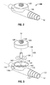
- FIG. 2 is a perspective view of a sampling port for use with the collection device of FIG. 1 ;
- FIG. 3 is a perspective view of the sampling port of FIG. 2 with various components separated;
- FIG. 4 is side plan view of the sampling port of FIG. 2 ;
- FIG. 5 is a side cross-sectional view of the sampling port of FIG. 2 ;
- FIGS. 6A-C are perspective views of a bladder of the sampling port in accordance with an embodiment of the present disclosure in various stages or positions of operation;
- FIG. 7 is a perspective view of a bezel of the sampling port of FIG. 2 in accordance with another aspect of the present disclosure
- FIG. 8 is a perspective view of a housing of the sampling port of FIG. 2 ;
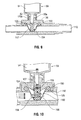
- FIG. 9 is a side cross-sectional view of the sampling port of FIG. 5 attached to a syringe.
- FIG. 10 is a partially enlarged cross-sectional view of the sampling port of FIG. 9 .
- proximal will refer to the end of a device or system that is closest to the operator, while the term “distal” will refer to the end of the device or system that is farthest from the operator.
- a biological fluid collection device is illustrated in FIG. 1 and is designated by the reference numeral 10.
- Fluid collection device 10 is used to collect fluid from a catheterized patient.
- Biological fluid collection device 10 includes a sampling port 100, a fluid collection bag 20, and a drain tube 30 fluidly interconnecting sampling port 100 and fluid collection bag 20.
- the fluid flows via a transfer tube (not shown) through sampling port 100 and into fluid collection bag 20 via drain tube 30.
- Drain tube 30 may include an anti-reflux valve 32 that restricts the back flow of fluid from collection bag 20 back into drain tube 30.
- Anti-reflux valve 32 can be secured to collection bag 20.
- Fluid collection bag 20 may further include a discharge valve 22 to selectively drain the fluid from collection bag 20.
- a vent opening 24 may be provided to let air into collection bag 20 to facilitate draining of the fluid from collection bag 20.
- sampling port 100 includes a housing 110 and a valve assembly 130 which is mountable to housing 110.
- Housing 110 defines longitudinal or housing axis "k" and longitudinal channel 112 which permits passage of the biological fluid through housing 110.
- Housing 110 includes inlet end 114 and outlet end 116 each for reception of tubing which is part of the fluid collection device 10.
- Inlet and outlet ends 114, 116 may include ridged surfaces or be stepped to enhance frictional engagement with the tubing.
- Either or both of inlet and outlet ends 114, 116 may include a circumferential wall segment for reception of the end of the tubing.
- Housing 110 further includes valve housing segment 140 which receives valve assembly 130.
- bezel 120 encloses bladder 150 in valve housing segment 140.
- Valve housing segment 140 includes transverse annular wall segment 118 arranged to define central port 142 and longitudinal wall segment 144. Central port 142 is fluidly couplable with longitudinal channel 112 of housing 110.
- Valve housing segment 140 may further include a circumferential recess 118a within longitudinal wall segment 144. Circumferential recess 118a facilitates mounting of valve assembly 130 to valve housing segment 140.
- valve assembly 130 includes bladder 150 and bezel 120.
- Bladder 150 includes bladder base 152 and bladder stem 154 which depends from the bladder base 152, as best illustrated in FIG. 6A .
- Bladder base 152 includes outer ring 156 and inner bladder segment 157 which is coterminous with bladder stem 154. At least inner bladder segment 157 of bladder base 152 includes an elastomeric material or membrane to permit the inner bladder segment 157 to stretch during its assembly and use.
- Bladder base 152 includes one or more openings 158 extending through inner bladder segment 157. Openings 158 permit passage of fluids from longitudinal channel 112 of housing 110.
- Bladder stem 154 defines outer wall 153 and fluid notch 155 extending through the remote end of bladder stem 154.
- Bladder stem 154 is more rigid than bladder base 152 and is dimensioned to be engaged by the syringe to actuate valve assembly 130. While bladder stem 154 is shown as a cylindrical shape, bladder stem 154 may be any shape that permits bladder stem 154 to at least partially engage bezel 120 when not actuated, as described below.
- bladder stem 154 may be frusto-conical or stepped.
- Bezel 120 may be a generally disc-shaped member including inner surface 125 and outer surface 128, and having a central channel 124 extending between the inner and outer surfaces 125, 128, as best seen in FIGS. 3 and 7 .
- Inner surface 125 includes peripheral recess 126 and internal area 123 depending inwardly from the peripheral recess 126.
- Internal area 123 may be tapered or obliquely arranged relative to valve axis "v.”
- Peripheral recess 126 accommodates outer ring 156 of bladder base 152 when in the assembled condition of the components (see Fig. 5 ).
- a plurality of axial internal recesses 127 may be arranged about central channel 124 adjacent inner surface 125.
- Axial internal recesses 127 are a component of the fluid path when the valve assembly 130 is in the actuated position, as discussed below.
- bladder stem 154 is a different shape, such as stepped or frusto-conical, the axial internal recesses 127 may not be necessary to provide the fluid path when the valve assembly 130 is in the actuated position.
- Bezel 120 and housing 110 are made of a rigid material, such as, for example, plastic (e.g., acrylonitrile butadiene styrene (ABS)), or metal. By making bezel 120 and housing 110 out of the same material, such as ABS, bezel 120 and housing 110 may be ultrasonically welded together. Alternatively, bezel 120 and housing 110 may be connected by any suitable means, such as by chemical welding or adhesives. Housing 110 can be any rigid structure that enables the passage of the fluid through longitudinal channel 112 defined therein, such as the housing of the Covidien SAFEGUARDTM urine sampling port.
- plastic e.g., acrylonitrile butadiene styrene (ABS)
- ABS acrylonitrile butadiene styrene
- Housing 110 can be any rigid structure that enables the passage of the fluid through longitudinal channel 112 defined therein, such as the housing of the Covidien SAFEGUARDTM urine sampling port.
- Bladder 150 may be an element which is filled with air or liquid, and may be selectively filled with a predetermined volume of fluid depending on design objectives. It is also envisioned that bladder 150 may be substantially solid. Bladder 150 may be, for example, an injection molded rubber part, but any other material with characteristics of rubber such as, for example, silicone and latex, may be used for bladder 150. As discussed above, bladder 150 includes bladder base 152 and bladder stem 154 which extends from a center portion of bladder base 152. Bladder base 152 includes inner bladder segment 157 and outer ring 156 which surrounds and reinforces an outer perimeter of inner bladder segment 157.
- At least inner bladder segment 157 of bladder base 152 includes an elastic material, such as an elastomer, to enable inner bladder segment 157 to stretch during actuation of valve assembly 130.
- Inner bladder segment 157 may define a plurality of openings 158 uniformly dispersed around the radial perimeter of bladder stem 154.
- Outer ring 156 is disposed within peripheral recess 126 of inner surface 125 of bezel 120 and circumferential recess 118a of valve housing segment 140, to facilitate secure positioning of bladder 150 in valve housing segment 140, as will be discussed below.
- the elastic nature of at least inner bladder segment 157 enables bladder 150 to assume various positions, such that bladder stem 154 is movable within central channel 124 of bezel 120 between a first position substantially preventing fluid flow through valve assembly 130 and a second position in which the fluid path is established through valve assembly 130 and in fluid communication with longitudinal channel 112 of housing 110 to thereby permit removal of a fluid sampling through central port 142 of valve housing segment 140.
- a neutral position such as prior to mounting bladder 150 relative to the exemplary housing 110 and there is no force applied to bladder 150, a bottom portion 159 of solid cylindrical bladder stem 154 and bladder base 152 are substantially coplanar with outer ring 156 of bladder base 152, as shown in FIG. 6A .
- fluid notch 155 of bladder stem 154 is substantially aligned with or positioned slightly below outer ring 156.
- the flexibility of inner bladder segment 157 of bladder 150 in conjunction with the plurality of openings 158 enables biological fluid to flow into a reservoir 160 defined by the inverse conical configuration of bladder 150, between bladder base 152 and inner surface 125 of bezel 120, as best seen in FIGS. 9 and 10 .
- bladder 150 when bladder 150 is in the second position as shown in FIG. 6C , bladder 150 permits passage of the fluid therethrough, and when bladder 150 is in the first position as shown in FIG. 6B , bladder 150 in conjunction with bezel 120 blocks passage of the fluid therethrough, as will be described in greater detail below. While specific relative positions of the bladder stem 154, fluid notch 155 and outer ring 156 are disclosed, it can be appreciated that other relative positions are within the scope of the invention and will depend on the specific configuration of the bezel 120 and bladder 150.
- bezel 120 is shown in FIGS. 3 and 7 .
- Bezel 120 is a fitting that can be attached to a housing, such as, for example, housing 110 shown, or modified to fit other housings, such as the Covidien SAFEGUARDTM urine sampling port housing.
- Bezel 120 encloses bladder 150 within valve housing segment 140, in a fluid-tight manner.
- inner surface 125 of bezel 120 may define peripheral recess 126 having a semi-circular cross-section.
- Peripheral recess 126 partially receives outer ring 156 of bladder base 152.
- peripheral recess 126 of bezel 120 in conjunction with circumferential recess 118a of valve housing segment 140 forms a peripheral groove having a circular cross-section dimensioned to receive the entire outer ring 156 of bladder 150.
- bezel 120 provides a central channel 124 configured and dimensioned to receive solid cylindrical bladder stem 154 of the exemplary bladder 150.
- bladder 150 is securely positioned within valve housing segment 140 by bezel 120 aided by outer ring 156 that rests in circumferential recess 118a of valve housing segment 140 and peripheral recess 126 of bezel 120, and solid cylindrical bladder stem 154 that is positioned within central channel 124 of bezel 120.
- the top portion of bladder stem 154 is flush with a top portion of bezel 120 when assembled.
- Central channel 124 of bezel 120 is dimensioned to receive a tip segment of a syringe, such that the tip segment of the syringe engages bladder stem 154 to move bladder stem 154 to the second position of bladder 150.
- inner surface 125 of bezel 120 may be inwardly, downwardly tapered toward central channel 124 and, more specifically, to a bottom portion of central channel 124 from peripheral recess 126. Tapered inner surface 125 of bezel 120 stretches inner bladder segment 157 of bladder 150 downward to create tension upon attachment. The tension helps enable bladder 150 to seal against the tapered inner surface 125 at the first position of bladder 150 and enables bladder stem 154 to fully return to the first position after being depressed down through central channel 124.
- bezel 120 may define a plurality of axial recesses 127 coaxially arranged about an axis "v" of central channel 124 and disposed adjacent inner surface 125.
- bezel 120 may include at least one internal rib surrounding central channel 124 and dimensioned to permit passage of fluid as a component of the fluid path when bladder stem 154 is in the second position.
- biological fluid pulled through openings 158 of inner bladder segment 157 by negative pressure created by the syringe travels through the plurality of axial recesses 127 to fluid notch 155 at the top portion of bladder stem 154, as will be described in greater detail below.
- Bezel 120 further includes an engagement portion 129 which extends from outer surface 128 of bezel 120, as shown in FIGS. 4 and 5 .
- Engagement portion 129 defines a channel therethough in communication with central channel 124.
- engagement portion 129 may have a conical taper configuration that enables a tightly sealed attachment with, for example, an ISO 594 compatible luer (as is used on standard syringes).
- an exterior surface of engagement portion 129 may include ISO 594 compatible luer lock threads 129a, such that a standard ISO 594 compatible luer lock syringe can be screwed thereon.
- the luer lock threads 129a in conjunction with the conical taper may provide a fitting fully compatible with ISO 594.
- an undeformed bladder 150 as described above in FIG. 6A is placed in valve housing segment 140.
- outer ring 156 of bladder 150 is partially received in circumferential recess 118a of housing 110.
- bladder 150 encloses central port 142 which serves as a conduit to longitudinal channel 112 through which biological fluid flows.
- solid cylindrical bladder stem 154 is concentrically aligned with central port 142.
- bezel 120 having tapered inner surface 125 is placed over bladder 150 and outer ring 156 of bladder base 152 is placed between circumferential recess 118a of valve housing segment 140 and peripheral recess 126 of bezel 120.
- Solid cylindrical bladder stem 154 of bladder 150 is movably positioned within central channel 124 of bezel 120.
- Bladder stem 154 is movable within the central channel 124 of bezel 120 between a first position substantially preventing fluid flow through valve assembly 130 and a second position in which a fluid path is established through valve assembly 130 and in fluid communication with longitudinal channel 112 of housing 110 to thereby permit removal of a fluid sampling through central port 142.
- Tapered inner surface 125 of bezel 120 may stretch inner bladder segment 157 of bladder 150 downward and into central port 142 to create tension, placing bladder 150 into the first position shown in FIG. 6B .
- a top portion of solid cylindrical bladder stem 154 is adjacent to a top portion of engagement portion 129 of bezel 120.
- Inner bladder segment 157 may be stretched and supported against tapered inner surface 125 of bezel 120.
- a smooth surface of inner surface 125 of bezel 120 may provide a seal against openings 158 defined in inner bladder segment 157 of bladder 150.
- Providing tension in inner bladder segment 157 may enable bladder 150 to provide a seal at rest and help bladder stem 154 to fully return to its first position after being depressed down through central channel 124, as will be described in detail below.
- a double seal may be created inside sampling port 100 between longitudinal channel 112 and the opening at the top portion of central channel 124 of bezel 120.
- the first seal may be created by the smooth surface of tapered inner surface 125 of bezel 120 pressed against bladder base 152.
- inner bladder segment 157 is stretched by inner surface 125 of bezel 120.
- the stretched inner bladder segment 157 is pressed against the smooth surface of inner surface 125.
- the second seal is created between solid cylindrical bladder stem 154 of bladder 150 and central channel 124 of bezel 120.
- Bladder stem 154 and central channel 124 are dimensioned to provide a long flush fit that will block fluid flow under normal pressure conditions. Fluid communication is established when fluid notch 155 of bladder 150 is positioned adjacent the plurality of axial internal recesses 127 coaxially arranged about an axis of central channel 124 of bezel 120.
- biological fluid collection system 10 including sampling port 100 is used in accordance with methods known by those skilled in the art.
- Stepped portion of housing 110 is connected to a transfer tube (not shown) which is connected to a catheter positioned within the bladder of a patient and the frusta-conical portion is connected to fluid collection bag 20.
- Sampling port 100 is assembled as shown in FIG. 5 , including housing 110 and valve assembly 130.
- a double seal may be maintained inside sampling port 100 between longitudinal channel 112 and an opening at the top portion of central channel 124 of bezel 120.
- a syringe 50 having a tip 50a is connected to sampling port 100.
- the tip 50a of an ISO 594 compatible luer fitting luer slip or luer lock syringe
- tip 50a is inserted into central channel 124 of bezel 120 and pushes solid cylindrical bladder stem 154 downward through central port 142 to or near the bottom surface of longitudinal channel 112. Since outer ring 156 is securely anchored in place within circumferential recess 118A of valve housing segment 140 and peripheral recess 126 of bezel 120 and enclosed by bezel 120, as bladder stem 154 is moved downward into channel 112, inner bladder segment 157 of bladder 150 is stretched by bladder stem 154 now resting at or near the bottom surface of longitudinal channel 112. As a result, bladder 150 at this time has an inverse conical shape, creating reservoir 160 between solid cylindrical bladder stem 154 and inner bladder segment 157.
- openings 158 defined in inner bladder segment 157 are now positioned within longitudinal channel 112, and thus within the stream of biological fluid.
- openings 158 that were pressed against the smooth tapered inner surface 125 of bezel 120, and thereby forming a seal, are now positioned within longitudinal channel 112 and provide fluid communication between longitudinal channel 112 and reservoir 160.
- bladder 150 When syringe 50 is detached from sampling port 100 and tip 50a is removed from central channel 124, bladder 150 returns to its first position to resume the double-seal condition within sampling port 100, preventing fluid from longitudinal channel 112 from flowing through openings 158 and fluid notch 155.
- Sampling port 100 of the present disclosure provides a low-profile configuration.
- the low-profile design is advantageous in a clinical setting because it is less likely to get caught onto other objects during use. Moreover, it is less likely to interfere with the patient, and thereby reducing injury or discomfort to patient. Furthermore, it is less likely to create an obstacle to a clinician during a medical procedure.
- sampling port 100 also offers the benefit of requiring fewer parts than other known biological fluid sampling ports. Such design may reduce manufacturing costs.
Landscapes
- Health & Medical Sciences (AREA)
- Life Sciences & Earth Sciences (AREA)
- General Health & Medical Sciences (AREA)
- Animal Behavior & Ethology (AREA)
- Engineering & Computer Science (AREA)
- Biomedical Technology (AREA)
- Heart & Thoracic Surgery (AREA)
- Veterinary Medicine (AREA)
- Public Health (AREA)
- Vascular Medicine (AREA)
- Epidemiology (AREA)
- Nursing (AREA)
- Orthopedic Medicine & Surgery (AREA)
- Hematology (AREA)
- Pathology (AREA)
- Medical Informatics (AREA)
- Molecular Biology (AREA)
- Surgery (AREA)
- Sampling And Sample Adjustment (AREA)
- Infusion, Injection, And Reservoir Apparatuses (AREA)
- External Artificial Organs (AREA)
Applications Claiming Priority (1)
| Application Number | Priority Date | Filing Date | Title |
|---|---|---|---|
| US12/877,473 US8522813B2 (en) | 2010-09-08 | 2010-09-08 | Needleless sampling port |
Publications (3)
| Publication Number | Publication Date |
|---|---|
| EP2428190A2 true EP2428190A2 (de) | 2012-03-14 |
| EP2428190A3 EP2428190A3 (de) | 2014-07-09 |
| EP2428190B1 EP2428190B1 (de) | 2016-03-16 |
Family
ID=44650855
Family Applications (1)
| Application Number | Title | Priority Date | Filing Date |
|---|---|---|---|
| EP11007228.7A Active EP2428190B1 (de) | 2010-09-08 | 2011-09-06 | Nadelloser Probenentnahmeanschluss |
Country Status (6)
| Country | Link |
|---|---|
| US (1) | US8522813B2 (de) |
| EP (1) | EP2428190B1 (de) |
| JP (2) | JP2012058242A (de) |
| AU (1) | AU2011221397B2 (de) |
| CA (1) | CA2751832C (de) |
| MX (1) | MX2011009429A (de) |
Cited By (2)
| Publication number | Priority date | Publication date | Assignee | Title |
|---|---|---|---|---|
| CN112220502A (zh) * | 2020-10-14 | 2021-01-15 | 吉林大学 | 一种用于辅助内镜留取标本的阀体装置 |
| EP4165162A4 (de) * | 2020-06-16 | 2025-12-17 | Saint Gobain Performance Plastics Corp | Probenahmesystem und verfahren zur verwendung davon |
Families Citing this family (59)
| Publication number | Priority date | Publication date | Assignee | Title |
|---|---|---|---|---|
| CN103182102B (zh) * | 2011-12-31 | 2016-03-30 | 北京万生人和科技有限公司 | 尿液引流装置、引流控制装置、引流控制系统 |
| WO2015131290A1 (en) | 2014-03-07 | 2015-09-11 | Tsytex E-Coatings Inc. | Temporary protective coating and removal system |
| US10952889B2 (en) | 2016-06-02 | 2021-03-23 | Purewick Corporation | Using wicking material to collect liquid for transport |
| US10226376B2 (en) | 2014-03-19 | 2019-03-12 | Purewick Corporation | Apparatus and methods for receiving discharged urine |
| US10390989B2 (en) | 2014-03-19 | 2019-08-27 | Purewick Corporation | Apparatus and methods for receiving discharged urine |
| US11376152B2 (en) | 2014-03-19 | 2022-07-05 | Purewick Corporation | Apparatus and methods for receiving discharged urine |
| JP6620237B2 (ja) * | 2015-10-30 | 2019-12-11 | シー・アール・バード・インコーポレーテッドC R Bard Incorporated | 通気アダプタ組立体、通気アダプタ組立体を作製する方法、通気アダプタ組立体を使用する方法及び通気アダプタ組立体を使用する排尿バッグシステム |
| US10376406B2 (en) | 2016-07-27 | 2019-08-13 | Purewick Corporation | Male urine collection device using wicking material |
| WO2018063499A1 (en) | 2016-09-29 | 2018-04-05 | Dignity Health | Catheter system for draining a bodily fluid from a fluid source in a body |
| WO2018144463A1 (en) | 2017-01-31 | 2018-08-09 | Purewick Corporation | Apparatus and methods for receiving discharged urine |
| JP7072084B2 (ja) | 2018-05-01 | 2022-05-19 | ピュアウィック コーポレイション | 流体収集装置、関連システム、及び関連方法 |
| AU2019262945B2 (en) | 2018-05-01 | 2022-08-25 | Purewick Corporation | Fluid collection devices and methods of using the same |
| US11944740B2 (en) | 2018-05-01 | 2024-04-02 | Purewick Corporation | Fluid collection devices, related systems, and related methods |
| AU2019262939A1 (en) | 2018-05-01 | 2020-11-26 | Purewick Corporation | Fluid collection devices, systems, and methods |
| EP3787569B1 (de) | 2018-05-01 | 2025-07-16 | Purewick Corporation | Flüssigkeitssammelvorrichtungen und -systeme |
| US20210161512A1 (en) * | 2018-05-22 | 2021-06-03 | C. R. Bard, Inc. | Urine-Sampling Kit And Methods Thereof |
| CA3143904C (en) | 2019-06-21 | 2023-11-28 | Purewick Corporation | Fluid collection devices including a base securement area, and related systems and methods |
| ES2961269T3 (es) | 2019-07-11 | 2024-03-11 | Purewick Corp | Dispositivos y sistemas de recogida de líquido |
| WO2021016026A1 (en) | 2019-07-19 | 2021-01-28 | Purewick Corporation | Fluid collection devices including at least one shape memory material |
| EP4051190B1 (de) * | 2019-10-28 | 2024-05-22 | Purewick Corporation | Fluidsammelanordnungen mit einem probenport |
| EP4559443A3 (de) | 2020-01-03 | 2025-06-18 | Purewick Corporation | Urinsammelvorrichtungen mit einem relativ breiten teil und einem länglichen teil und zugehörige verfahren |
| WO2021188817A1 (en) | 2020-03-19 | 2021-09-23 | Purewick Corporation | Fluid collection assemblies including one or more movement enhancing features |
| US12521288B2 (en) | 2020-03-26 | 2026-01-13 | Purewick Corporation | Multi-layer urine capture device and related methods |
| WO2021207621A1 (en) | 2020-04-10 | 2021-10-14 | Purewick Corporation | Fluid collection assemblies including one or more leak prevention features |
| US12465514B2 (en) | 2020-04-17 | 2025-11-11 | Purewick Corporation | Fluid collection devices, systems, and methods securing a protruding portion in position for use |
| US12472090B2 (en) | 2020-04-17 | 2025-11-18 | Purewick Corporation | Female external catheter devices having a urethral cup, and related systems and methods |
| WO2021211801A1 (en) | 2020-04-17 | 2021-10-21 | Purewick Corporation | Fluid collection assemblies including a fluid impermeable barrier having a sump and a base |
| US12491104B2 (en) | 2020-04-20 | 2025-12-09 | Purewick Corporation | Fluid collection devices adjustable between a vacuum-based orientation and a gravity-based orientation, and related systems and methods |
| US12048643B2 (en) | 2020-05-27 | 2024-07-30 | Purewick Corporation | Fluid collection assemblies including at least one inflation device and methods and systems of using the same |
| US12440371B2 (en) | 2020-08-06 | 2025-10-14 | Purewick Corporation | Fluid collection system including a garment and a fluid collection device |
| US12350187B2 (en) | 2020-08-11 | 2025-07-08 | Purewick Corporation | Fluid collection assemblies defining waist and leg openings |
| EP4210643A1 (de) | 2020-09-09 | 2023-07-19 | Purewick Corporation | Flüssigkeitssammelvorrichtungen, -systeme und -verfahren |
| US12156792B2 (en) | 2020-09-10 | 2024-12-03 | Purewick Corporation | Fluid collection assemblies including at least one inflation device |
| US12042423B2 (en) | 2020-10-07 | 2024-07-23 | Purewick Corporation | Fluid collection systems including at least one tensioning element |
| US12440370B2 (en) | 2020-10-21 | 2025-10-14 | Purewick Corporation | Apparatus with compressible casing for receiving discharged urine |
| US12569365B2 (en) | 2020-10-21 | 2026-03-10 | Purewick Corporation | Fluid collection assemblies including at least one shape memory material disposed in the conduit |
| US12208031B2 (en) | 2020-10-21 | 2025-01-28 | Purewick Corporation | Adapters for fluid collection devices |
| US12257174B2 (en) | 2020-10-21 | 2025-03-25 | Purewick Corporation | Fluid collection assemblies including at least one of a protrusion or at least one expandable material |
| US12048644B2 (en) | 2020-11-03 | 2024-07-30 | Purewick Corporation | Apparatus for receiving discharged urine |
| US12070432B2 (en) | 2020-11-11 | 2024-08-27 | Purewick Corporation | Urine collection system including a flow meter and related methods |
| US12245967B2 (en) | 2020-11-18 | 2025-03-11 | Purewick Corporation | Fluid collection assemblies including an adjustable spine |
| US12599495B2 (en) | 2021-01-05 | 2026-04-14 | Purewick Corporation | Male external catheter with attachment interface configured to bias against penis |
| US12268627B2 (en) | 2021-01-06 | 2025-04-08 | Purewick Corporation | Fluid collection assemblies including at least one securement body |
| JP2024503636A (ja) | 2021-01-07 | 2024-01-26 | ピュアウィック コーポレイション | 車椅子に固定可能な尿収集システムおよび関連する方法 |
| EP4349306A3 (de) | 2021-01-19 | 2024-06-05 | Purewick Corporation | Flüssigkeitssammelvorrichtungen mit variabler passform, systeme und verfahren |
| US12178735B2 (en) | 2021-02-09 | 2024-12-31 | Purewick Corporation | Noise reduction for a urine suction system |
| EP4274524B1 (de) | 2021-02-26 | 2024-08-28 | Purewick Corporation | Flüssigkeitsaufnahmegerät, konfiguriert als ein männliches urinaufnahmegerät |
| US12558472B2 (en) | 2021-03-05 | 2026-02-24 | Purewick Corporation | Portable fluid collection systems with storage and related methods |
| US12551385B2 (en) | 2021-03-05 | 2026-02-17 | Purewick Corporation | Fluid collection assembly including a tube having porous wicking material for improved fluid transport |
| US12458525B2 (en) | 2021-03-10 | 2025-11-04 | Purewick Corporation | Acoustic silencer for a urine suction system |
| US12029677B2 (en) | 2021-04-06 | 2024-07-09 | Purewick Corporation | Fluid collection devices having a collection bag, and related systems and methods |
| US12233003B2 (en) | 2021-04-29 | 2025-02-25 | Purewick Corporation | Fluid collection assemblies including at least one length adjusting feature |
| US12251333B2 (en) | 2021-05-21 | 2025-03-18 | Purewick Corporation | Fluid collection assemblies including at least one inflation device and methods and systems of using the same |
| US12324767B2 (en) | 2021-05-24 | 2025-06-10 | Purewick Corporation | Fluid collection assembly including a customizable external support and related methods |
| US12150885B2 (en) | 2021-05-26 | 2024-11-26 | Purewick Corporation | Fluid collection system including a cleaning system and methods |
| US12575960B2 (en) | 2021-06-24 | 2026-03-17 | Purewick Corporation | Urine collection systems having one or more of volume, pressure, or flow indicators, and related methods |
| US12551366B2 (en) | 2021-08-02 | 2026-02-17 | Purewick Corporation | Fluid collection devices having multiple fluid collection regions, and related systems and methods |
| US12594062B2 (en) | 2021-09-08 | 2026-04-07 | Purewick Corporation | Fluid collection assemblies including an extension |
| CN117231834B (zh) * | 2023-11-15 | 2024-06-25 | 泰州市恩博机械有限公司 | 一种可拆卸具有高密封性的金属软管 |
Family Cites Families (27)
| Publication number | Priority date | Publication date | Assignee | Title |
|---|---|---|---|---|
| US3930413A (en) * | 1972-12-07 | 1976-01-06 | Caterpillar Tractor Co. | Quick release gauge fitting |
| US4116227A (en) | 1976-06-28 | 1978-09-26 | Plasco, Inc. | Combination catheter venting and urine sample collecting unit and method of making the same |
| US4533354A (en) | 1982-09-30 | 1985-08-06 | E. R. Squibb & Sons, Inc. | Medical drainage bag and non-return valve assembly |
| JPS5989241U (ja) * | 1982-12-07 | 1984-06-16 | 株式会社クラレ | 臭気濃度測定用の臭気希釈装置 |
| JPS6045039U (ja) * | 1983-09-06 | 1985-03-29 | テルモ株式会社 | 逆止弁 |
| US4728324A (en) * | 1986-10-15 | 1988-03-01 | The Kendall Company | Urine meter valve with tamper indicator |
| US4815477A (en) | 1986-10-15 | 1989-03-28 | The Kendall Company | Urine meter drain container with large and small sample ports |
| US4927605A (en) | 1987-04-22 | 1990-05-22 | Wadley Technologies, Inc. | Specimen collection and sampling container |
| GB9103122D0 (en) | 1991-02-14 | 1991-04-03 | Wallace Ltd H G | Resealable sampling port |
| US5360413A (en) | 1991-12-06 | 1994-11-01 | Filtertek, Inc. | Needleless access device |
| US5620434A (en) * | 1994-03-14 | 1997-04-15 | Brony; Seth K. | Medicine vial link for needleless syringes |
| DK107394A (da) * | 1994-09-16 | 1996-03-17 | Uno Plast As | Anordning til måling og opsamling af legemsvæske |
| US5810768A (en) * | 1995-06-07 | 1998-09-22 | Icu Medical, Inc. | Medical connector |
| US5616138A (en) | 1995-08-29 | 1997-04-01 | Tri State Hospital Supply Corporation | Urine drainage and collection device |
| US5573516A (en) * | 1995-09-18 | 1996-11-12 | Medical Connexions, Inc. | Needleless connector |
| EP0956088B1 (de) * | 1996-12-16 | 2010-07-28 | ICU Medical, Inc. | Positives durchflussventil |
| JPH10192415A (ja) * | 1996-12-27 | 1998-07-28 | Jms Co Ltd | ニードルレス側注管 |
| US6132407A (en) | 1997-02-06 | 2000-10-17 | C. R. Bard, Inc. | Outlet tube device for urinary drainage bag |
| US5919146A (en) | 1997-02-06 | 1999-07-06 | Tri-State Hospital Supply Corp. | Urine sampling and drainage device |
| JP3761411B2 (ja) * | 2000-10-02 | 2006-03-29 | フカイ工業株式会社 | 逆止弁付栓体 |
| US6716200B2 (en) | 2002-01-18 | 2004-04-06 | C.R. Bard, Inc. | Antimicrobial urine collection system and methods of manufacturing the same |
| US20060189926A1 (en) | 2005-02-14 | 2006-08-24 | Hall W D | Apparatus and methods for analyzing body fluid samples |
| US8100866B2 (en) * | 2005-03-24 | 2012-01-24 | B. Braun Medical Inc. | Needleless access port valves |
| US7314061B2 (en) * | 2005-03-25 | 2008-01-01 | B. Braun Medical Inc. | Needleless access port valves |
| US20070203463A1 (en) * | 2006-02-24 | 2007-08-30 | Larry Salvadori | Urine collection system with needleless sampling port |
| US7867204B2 (en) * | 2006-05-04 | 2011-01-11 | B. Braun Medical Inc. | Needleless access port valves |
| US7981090B2 (en) | 2006-10-18 | 2011-07-19 | Baxter International Inc. | Luer activated device |
-
2010
- 2010-09-08 US US12/877,473 patent/US8522813B2/en active Active
-
2011
- 2011-09-06 EP EP11007228.7A patent/EP2428190B1/de active Active
- 2011-09-07 CA CA2751832A patent/CA2751832C/en active Active
- 2011-09-07 JP JP2011195032A patent/JP2012058242A/ja not_active Withdrawn
- 2011-09-08 MX MX2011009429A patent/MX2011009429A/es active IP Right Grant
- 2011-09-08 AU AU2011221397A patent/AU2011221397B2/en active Active
-
2013
- 2013-07-10 JP JP2013144548A patent/JP5947754B2/ja active Active
Non-Patent Citations (1)
| Title |
|---|
| None |
Cited By (2)
| Publication number | Priority date | Publication date | Assignee | Title |
|---|---|---|---|---|
| EP4165162A4 (de) * | 2020-06-16 | 2025-12-17 | Saint Gobain Performance Plastics Corp | Probenahmesystem und verfahren zur verwendung davon |
| CN112220502A (zh) * | 2020-10-14 | 2021-01-15 | 吉林大学 | 一种用于辅助内镜留取标本的阀体装置 |
Also Published As
| Publication number | Publication date |
|---|---|
| EP2428190B1 (de) | 2016-03-16 |
| AU2011221397B2 (en) | 2013-09-12 |
| CA2751832C (en) | 2014-06-17 |
| MX2011009429A (es) | 2012-03-22 |
| US8522813B2 (en) | 2013-09-03 |
| JP2013238608A (ja) | 2013-11-28 |
| JP5947754B2 (ja) | 2016-07-06 |
| AU2011221397A1 (en) | 2012-03-22 |
| CA2751832A1 (en) | 2012-03-08 |
| JP2012058242A (ja) | 2012-03-22 |
| EP2428190A3 (de) | 2014-07-09 |
| US20120055271A1 (en) | 2012-03-08 |
Similar Documents
| Publication | Publication Date | Title |
|---|---|---|
| CA2751832C (en) | Needleless sampling port | |
| US12257051B2 (en) | Blood contaminant sequestration device with one-way air valve and air-permeable blood barrier with closure mechanism | |
| US20250375128A1 (en) | Blood sample optimization device | |
| US20210361207A1 (en) | Fluid optimization and contaminant containment device and method using displaceable plug | |
| CN101395459B (zh) | 试样的采集方法、检验方法以及用于它们的移液管、试样采集器具 | |
| US10376684B2 (en) | Multi-functional medical sampling port and method of using same | |
| US11617525B2 (en) | Blood contaminant sequestration device with passive fluid control junction | |
| WO2006088501A1 (en) | Blood collecting devices | |
| CA2579892A1 (en) | Urine collection system with needleless sampling port | |
| US7604138B2 (en) | Closure device for a container | |
| WO1992004867A1 (en) | A blood sampling device | |
| US20200022630A1 (en) | Removal port for removing a fluid, system and use of a removal port | |
| WO2021247609A1 (en) | Fluid optimization and contaminant containment device and method using displaceable plug | |
| WO2021183153A1 (en) | Blood contaminant sequestration device with passive fluid control junction | |
| WO2015117126A1 (en) | Medical valve | |
| WO2024197226A2 (en) | Bidirectional stopper valve that mates to a venting syringe | |
| EP4117521A1 (de) | Vorrichtung zur sequestrierung von blutverunreinigungen mit passivem fluidsteuerungsanschluss | |
| HK40019673B (en) | Blood sample optimization system and blood contaminant sequestration device | |
| HK40019673A (en) | Blood sample optimization system and blood contaminant sequestration device |
Legal Events
| Date | Code | Title | Description |
|---|---|---|---|
| 17P | Request for examination filed |
Effective date: 20110906 |
|
| AK | Designated contracting states |
Kind code of ref document: A2 Designated state(s): AL AT BE BG CH CY CZ DE DK EE ES FI FR GB GR HR HU IE IS IT LI LT LU LV MC MK MT NL NO PL PT RO RS SE SI SK SM TR |
|
| AX | Request for extension of the european patent |
Extension state: BA ME |
|
| PUAI | Public reference made under article 153(3) epc to a published international application that has entered the european phase |
Free format text: ORIGINAL CODE: 0009012 |
|
| RAP1 | Party data changed (applicant data changed or rights of an application transferred) |
Owner name: COVIDIEN LP |
|
| PUAL | Search report despatched |
Free format text: ORIGINAL CODE: 0009013 |
|
| AK | Designated contracting states |
Kind code of ref document: A3 Designated state(s): AL AT BE BG CH CY CZ DE DK EE ES FI FR GB GR HR HU IE IS IT LI LT LU LV MC MK MT NL NO PL PT RO RS SE SI SK SM TR |
|
| AX | Request for extension of the european patent |
Extension state: BA ME |
|
| RIC1 | Information provided on ipc code assigned before grant |
Ipc: A61F 5/44 20060101AFI20140603BHEP Ipc: A61B 10/00 20060101ALI20140603BHEP |
|
| GRAP | Despatch of communication of intention to grant a patent |
Free format text: ORIGINAL CODE: EPIDOSNIGR1 |
|
| INTG | Intention to grant announced |
Effective date: 20150916 |
|
| GRAS | Grant fee paid |
Free format text: ORIGINAL CODE: EPIDOSNIGR3 |
|
| GRAA | (expected) grant |
Free format text: ORIGINAL CODE: 0009210 |
|
| AK | Designated contracting states |
Kind code of ref document: B1 Designated state(s): AL AT BE BG CH CY CZ DE DK EE ES FI FR GB GR HR HU IE IS IT LI LT LU LV MC MK MT NL NO PL PT RO RS SE SI SK SM TR |
|
| REG | Reference to a national code |
Ref country code: GB Ref legal event code: FG4D |
|
| REG | Reference to a national code |
Ref country code: CH Ref legal event code: EP |
|
| REG | Reference to a national code |
Ref country code: IE Ref legal event code: FG4D |
|
| REG | Reference to a national code |
Ref country code: AT Ref legal event code: REF Ref document number: 780539 Country of ref document: AT Kind code of ref document: T Effective date: 20160415 |
|
| REG | Reference to a national code |
Ref country code: DE Ref legal event code: R096 Ref document number: 602011023960 Country of ref document: DE |
|
| REG | Reference to a national code |
Ref country code: NL Ref legal event code: MP Effective date: 20160316 |
|
| REG | Reference to a national code |
Ref country code: LT Ref legal event code: MG4D |
|
| PG25 | Lapsed in a contracting state [announced via postgrant information from national office to epo] |
Ref country code: NO Free format text: LAPSE BECAUSE OF FAILURE TO SUBMIT A TRANSLATION OF THE DESCRIPTION OR TO PAY THE FEE WITHIN THE PRESCRIBED TIME-LIMIT Effective date: 20160616 Ref country code: GR Free format text: LAPSE BECAUSE OF FAILURE TO SUBMIT A TRANSLATION OF THE DESCRIPTION OR TO PAY THE FEE WITHIN THE PRESCRIBED TIME-LIMIT Effective date: 20160617 Ref country code: HR Free format text: LAPSE BECAUSE OF FAILURE TO SUBMIT A TRANSLATION OF THE DESCRIPTION OR TO PAY THE FEE WITHIN THE PRESCRIBED TIME-LIMIT Effective date: 20160316 Ref country code: FI Free format text: LAPSE BECAUSE OF FAILURE TO SUBMIT A TRANSLATION OF THE DESCRIPTION OR TO PAY THE FEE WITHIN THE PRESCRIBED TIME-LIMIT Effective date: 20160316 |
|
| REG | Reference to a national code |
Ref country code: AT Ref legal event code: MK05 Ref document number: 780539 Country of ref document: AT Kind code of ref document: T Effective date: 20160316 |
|
| REG | Reference to a national code |
Ref country code: FR Ref legal event code: PLFP Year of fee payment: 6 |
|
| PG25 | Lapsed in a contracting state [announced via postgrant information from national office to epo] |
Ref country code: SE Free format text: LAPSE BECAUSE OF FAILURE TO SUBMIT A TRANSLATION OF THE DESCRIPTION OR TO PAY THE FEE WITHIN THE PRESCRIBED TIME-LIMIT Effective date: 20160316 Ref country code: RS Free format text: LAPSE BECAUSE OF FAILURE TO SUBMIT A TRANSLATION OF THE DESCRIPTION OR TO PAY THE FEE WITHIN THE PRESCRIBED TIME-LIMIT Effective date: 20160316 Ref country code: LT Free format text: LAPSE BECAUSE OF FAILURE TO SUBMIT A TRANSLATION OF THE DESCRIPTION OR TO PAY THE FEE WITHIN THE PRESCRIBED TIME-LIMIT Effective date: 20160316 Ref country code: LV Free format text: LAPSE BECAUSE OF FAILURE TO SUBMIT A TRANSLATION OF THE DESCRIPTION OR TO PAY THE FEE WITHIN THE PRESCRIBED TIME-LIMIT Effective date: 20160316 Ref country code: NL Free format text: LAPSE BECAUSE OF FAILURE TO SUBMIT A TRANSLATION OF THE DESCRIPTION OR TO PAY THE FEE WITHIN THE PRESCRIBED TIME-LIMIT Effective date: 20160316 |
|
| PG25 | Lapsed in a contracting state [announced via postgrant information from national office to epo] |
Ref country code: IS Free format text: LAPSE BECAUSE OF FAILURE TO SUBMIT A TRANSLATION OF THE DESCRIPTION OR TO PAY THE FEE WITHIN THE PRESCRIBED TIME-LIMIT Effective date: 20160716 Ref country code: EE Free format text: LAPSE BECAUSE OF FAILURE TO SUBMIT A TRANSLATION OF THE DESCRIPTION OR TO PAY THE FEE WITHIN THE PRESCRIBED TIME-LIMIT Effective date: 20160316 Ref country code: PL Free format text: LAPSE BECAUSE OF FAILURE TO SUBMIT A TRANSLATION OF THE DESCRIPTION OR TO PAY THE FEE WITHIN THE PRESCRIBED TIME-LIMIT Effective date: 20160316 |
|
| PG25 | Lapsed in a contracting state [announced via postgrant information from national office to epo] |
Ref country code: RO Free format text: LAPSE BECAUSE OF FAILURE TO SUBMIT A TRANSLATION OF THE DESCRIPTION OR TO PAY THE FEE WITHIN THE PRESCRIBED TIME-LIMIT Effective date: 20160316 Ref country code: SK Free format text: LAPSE BECAUSE OF FAILURE TO SUBMIT A TRANSLATION OF THE DESCRIPTION OR TO PAY THE FEE WITHIN THE PRESCRIBED TIME-LIMIT Effective date: 20160316 Ref country code: CZ Free format text: LAPSE BECAUSE OF FAILURE TO SUBMIT A TRANSLATION OF THE DESCRIPTION OR TO PAY THE FEE WITHIN THE PRESCRIBED TIME-LIMIT Effective date: 20160316 Ref country code: PT Free format text: LAPSE BECAUSE OF FAILURE TO SUBMIT A TRANSLATION OF THE DESCRIPTION OR TO PAY THE FEE WITHIN THE PRESCRIBED TIME-LIMIT Effective date: 20160718 Ref country code: AT Free format text: LAPSE BECAUSE OF FAILURE TO SUBMIT A TRANSLATION OF THE DESCRIPTION OR TO PAY THE FEE WITHIN THE PRESCRIBED TIME-LIMIT Effective date: 20160316 Ref country code: SM Free format text: LAPSE BECAUSE OF FAILURE TO SUBMIT A TRANSLATION OF THE DESCRIPTION OR TO PAY THE FEE WITHIN THE PRESCRIBED TIME-LIMIT Effective date: 20160316 Ref country code: ES Free format text: LAPSE BECAUSE OF FAILURE TO SUBMIT A TRANSLATION OF THE DESCRIPTION OR TO PAY THE FEE WITHIN THE PRESCRIBED TIME-LIMIT Effective date: 20160316 |
|
| REG | Reference to a national code |
Ref country code: DE Ref legal event code: R097 Ref document number: 602011023960 Country of ref document: DE |
|
| PG25 | Lapsed in a contracting state [announced via postgrant information from national office to epo] |
Ref country code: BE Free format text: LAPSE BECAUSE OF FAILURE TO SUBMIT A TRANSLATION OF THE DESCRIPTION OR TO PAY THE FEE WITHIN THE PRESCRIBED TIME-LIMIT Effective date: 20160316 Ref country code: IT Free format text: LAPSE BECAUSE OF FAILURE TO SUBMIT A TRANSLATION OF THE DESCRIPTION OR TO PAY THE FEE WITHIN THE PRESCRIBED TIME-LIMIT Effective date: 20160316 |
|
| PLBE | No opposition filed within time limit |
Free format text: ORIGINAL CODE: 0009261 |
|
| STAA | Information on the status of an ep patent application or granted ep patent |
Free format text: STATUS: NO OPPOSITION FILED WITHIN TIME LIMIT |
|
| PG25 | Lapsed in a contracting state [announced via postgrant information from national office to epo] |
Ref country code: DK Free format text: LAPSE BECAUSE OF FAILURE TO SUBMIT A TRANSLATION OF THE DESCRIPTION OR TO PAY THE FEE WITHIN THE PRESCRIBED TIME-LIMIT Effective date: 20160316 |
|
| 26N | No opposition filed |
Effective date: 20161219 |
|
| PG25 | Lapsed in a contracting state [announced via postgrant information from national office to epo] |
Ref country code: BG Free format text: LAPSE BECAUSE OF FAILURE TO SUBMIT A TRANSLATION OF THE DESCRIPTION OR TO PAY THE FEE WITHIN THE PRESCRIBED TIME-LIMIT Effective date: 20160616 |
|
| PG25 | Lapsed in a contracting state [announced via postgrant information from national office to epo] |
Ref country code: MC Free format text: LAPSE BECAUSE OF FAILURE TO SUBMIT A TRANSLATION OF THE DESCRIPTION OR TO PAY THE FEE WITHIN THE PRESCRIBED TIME-LIMIT Effective date: 20160316 |
|
| REG | Reference to a national code |
Ref country code: CH Ref legal event code: PL |
|
| PG25 | Lapsed in a contracting state [announced via postgrant information from national office to epo] |
Ref country code: SI Free format text: LAPSE BECAUSE OF FAILURE TO SUBMIT A TRANSLATION OF THE DESCRIPTION OR TO PAY THE FEE WITHIN THE PRESCRIBED TIME-LIMIT Effective date: 20160316 |
|
| PG25 | Lapsed in a contracting state [announced via postgrant information from national office to epo] |
Ref country code: CH Free format text: LAPSE BECAUSE OF NON-PAYMENT OF DUE FEES Effective date: 20160930 Ref country code: LI Free format text: LAPSE BECAUSE OF NON-PAYMENT OF DUE FEES Effective date: 20160930 |
|
| REG | Reference to a national code |
Ref country code: FR Ref legal event code: PLFP Year of fee payment: 7 |
|
| PG25 | Lapsed in a contracting state [announced via postgrant information from national office to epo] |
Ref country code: LU Free format text: LAPSE BECAUSE OF NON-PAYMENT OF DUE FEES Effective date: 20160906 |
|
| REG | Reference to a national code |
Ref country code: GB Ref legal event code: 732E Free format text: REGISTERED BETWEEN 20180208 AND 20180214 |
|
| PG25 | Lapsed in a contracting state [announced via postgrant information from national office to epo] |
Ref country code: CY Free format text: LAPSE BECAUSE OF FAILURE TO SUBMIT A TRANSLATION OF THE DESCRIPTION OR TO PAY THE FEE WITHIN THE PRESCRIBED TIME-LIMIT Effective date: 20160316 Ref country code: HU Free format text: LAPSE BECAUSE OF FAILURE TO SUBMIT A TRANSLATION OF THE DESCRIPTION OR TO PAY THE FEE WITHIN THE PRESCRIBED TIME-LIMIT; INVALID AB INITIO Effective date: 20110906 |
|
| PG25 | Lapsed in a contracting state [announced via postgrant information from national office to epo] |
Ref country code: TR Free format text: LAPSE BECAUSE OF FAILURE TO SUBMIT A TRANSLATION OF THE DESCRIPTION OR TO PAY THE FEE WITHIN THE PRESCRIBED TIME-LIMIT Effective date: 20160316 Ref country code: MT Free format text: LAPSE BECAUSE OF NON-PAYMENT OF DUE FEES Effective date: 20160930 Ref country code: MK Free format text: LAPSE BECAUSE OF FAILURE TO SUBMIT A TRANSLATION OF THE DESCRIPTION OR TO PAY THE FEE WITHIN THE PRESCRIBED TIME-LIMIT Effective date: 20160316 |
|
| REG | Reference to a national code |
Ref country code: FR Ref legal event code: PLFP Year of fee payment: 8 |
|
| PG25 | Lapsed in a contracting state [announced via postgrant information from national office to epo] |
Ref country code: AL Free format text: LAPSE BECAUSE OF FAILURE TO SUBMIT A TRANSLATION OF THE DESCRIPTION OR TO PAY THE FEE WITHIN THE PRESCRIBED TIME-LIMIT Effective date: 20160316 |
|
| PGFP | Annual fee paid to national office [announced via postgrant information from national office to epo] |
Ref country code: DE Payment date: 20250929 Year of fee payment: 15 |
|
| PGFP | Annual fee paid to national office [announced via postgrant information from national office to epo] |
Ref country code: GB Payment date: 20250929 Year of fee payment: 15 |
|
| PGFP | Annual fee paid to national office [announced via postgrant information from national office to epo] |
Ref country code: FR Payment date: 20250925 Year of fee payment: 15 |
|
| PGFP | Annual fee paid to national office [announced via postgrant information from national office to epo] |
Ref country code: IE Payment date: 20250929 Year of fee payment: 15 |