EP2428735A2 - Appareil de cuisson doté d'un générateur de vapeur et procédé de réglage d'un générateur de vapeur pour un appareil de cuisson - Google Patents
Appareil de cuisson doté d'un générateur de vapeur et procédé de réglage d'un générateur de vapeur pour un appareil de cuisson Download PDFInfo
- Publication number
- EP2428735A2 EP2428735A2 EP11007208A EP11007208A EP2428735A2 EP 2428735 A2 EP2428735 A2 EP 2428735A2 EP 11007208 A EP11007208 A EP 11007208A EP 11007208 A EP11007208 A EP 11007208A EP 2428735 A2 EP2428735 A2 EP 2428735A2
- Authority
- EP
- European Patent Office
- Prior art keywords
- controller
- steam generator
- power
- cooking appliance
- cooking
- Prior art date
- Legal status (The legal status is an assumption and is not a legal conclusion. Google has not performed a legal analysis and makes no representation as to the accuracy of the status listed.)
- Granted
Links
Images



Classifications
-
- F—MECHANICAL ENGINEERING; LIGHTING; HEATING; WEAPONS; BLASTING
- F24—HEATING; RANGES; VENTILATING
- F24C—DOMESTIC STOVES OR RANGES ; DETAILS OF DOMESTIC STOVES OR RANGES, OF GENERAL APPLICATION
- F24C7/00—Stoves or ranges heated by electric energy
- F24C7/08—Arrangement or mounting of control or safety devices
-
- F—MECHANICAL ENGINEERING; LIGHTING; HEATING; WEAPONS; BLASTING
- F24—HEATING; RANGES; VENTILATING
- F24C—DOMESTIC STOVES OR RANGES ; DETAILS OF DOMESTIC STOVES OR RANGES, OF GENERAL APPLICATION
- F24C15/00—Details
- F24C15/32—Arrangements of ducts for hot gases, e.g. in or around baking ovens
- F24C15/322—Arrangements of ducts for hot gases, e.g. in or around baking ovens with forced circulation
- F24C15/327—Arrangements of ducts for hot gases, e.g. in or around baking ovens with forced circulation with air moisturising
Definitions
- the invention relates to a cooking appliance with a cooking chamber and a steam generator.
- the invention further relates to a method for controlling a steam generator for a cooking appliance.
- threshold controllers In cooking appliances for temperature or humidity control threshold regulators are usually used because they can be used usually without specific adaptation to the device size, the type of heating (gas or electric) and the load in the oven. In steam mode, however, threshold controllers have serious disadvantages if a high steam content in the cooking chamber is to be maintained.
- a threshold controller controls between an upper threshold and a lower threshold. If the upper threshold has been exceeded, the steam generator is switched off. Subsequently, the temperature is reduced by condensing the water vapor inside the cooking chamber (for example, to be cooked products). At the same time, the volume of the gas contained in the interior of the cooking chamber is reduced, so that air has to be sucked in, usually from a condensation or drainage region of the cooking appliance.
- the steam generator is switched on again. Thereafter, water vapor is again produced until the temperature in the cooking chamber has again reached the upper threshold.
- a cooking appliance with a cooking chamber, a steam generator and a controller is provided according to the invention, wherein the controller has a threshold controller and a steady controller.
- the invention is based on the idea of controlling the steam generator in an operating range in which the steam content is to be kept constant, with the signal of the continuous controller. This prevents the steam generator from being switched off until air has been sucked in.
- the steam generator has at least two power levels.
- the steam generator is in principle still operated with discrete power levels, but in the operating range in which the steam content is to be kept constant, are controlled by the continuous controller. By using two or more power levels, an optimal adaptation to the respective power requirement can be made.
- the continuous controller operates the steam generator with a maximum average power, which is below the first power level.
- the steam generator then works with a holding stage, which can be integrated into the threshold controller like an additional smaller heating stage.
- the first power level is in the range of about 25% to about 50% of the second, maximum power level. It has been found that with such a spreading of the heating stages, the desired performance can be well represented. In addition, these power levels result constructively in an advantageous manner. In an electrically operated steam generator halving the power in star or delta connection can be achieved with a relay or SSR. In the case of a gas-driven steam generator, on the other hand, the smallest heating level will have a capacity of approximately 25% of the maximum power, even if lower powers could be advantageous.
- the continuous controller operates the steam generator with a power that is about 75% of the power of the first power level.
- the steam generator operates at a power of 37.5% of the maximum heating power, which has proven to be advantageous in order to maintain a constant steam content in the cooking space ,
- the continuous controller outputs as a control variable a buffer variable, by means of which the controller operates the steam generator in pulse width modulation.
- a buffer variable by means of which the controller operates the steam generator in pulse width modulation.
- the cooking chamber is in flow communication with a drain region, wherein in the drain region, a steam buffer is formed whose volume is at least equal to the vapor volume condensed between two heating pulses in the cooking chamber.
- a steam buffer is formed whose volume is at least equal to the vapor volume condensed between two heating pulses in the cooking chamber.
- the continuous controller is a PI controller.
- a controller is sufficient to maintain the setpoint (temperature or humidity) to be maintained in the cooking chamber during the holding phase.
- a more elaborate PID controller can be dispensed with.
- a method for controlling a steam generator for a cooking appliance for achieving the abovementioned object, which is characterized in that the steam generator differs greatly from a desired value in an approach phase in which an actual value to be regulated in a cooking chamber of the cooking appliance differs. is controlled by a threshold controller and is controlled by a continuous controller in a subsequent holding phase in which the actual value is in the vicinity of the setpoint.
- This method combines the advantage of a robust threshold controller with the advantage of more precise control by means of a continuous regulator.
- the threshold controller controls the steam generator until the actual value to be regulated in the cooking chamber is at least 90% of the desired value. It simplifies the design of the continuous controller if it only has to take over control in the vicinity of the setpoint and the approach to the setpoint is taken over by the robust threshold controller.
- the continuous controller continuously regulates the steam generator. In this way, the quality of control can be increased and the energy consumption can be reduced.
- FIG. 1 schematically a cooking appliance 10 is shown, which is intended for commercial kitchens and is known as a combination damper. It contains a cooking chamber 12, can be introduced into the products to be cooked. It is a steam generator 14 is provided which can generate water vapor, which can be passed into the interior of the cooking chamber 12.
- the cooking appliance 10 also has a heater in order to introduce heated air into the cooking chamber. However, since this heater in the context of the present application without meaning, it is not shown here for the sake of clarity.
- a controller 16 which receives as input signals, inter alia, a signal from a temperature and / or humidity sensor 18, which is arranged in the interior of the cooking chamber 12, and by an operating unit 20.
- an operator can different cooking conditions in Inside the cooking chamber or select more complex cooking programs.
- the controller 16 includes a threshold controller 22 and a continuous controller 24, which is designed here as a PI controller.
- the controller 16 controls the steam generator 14 by specifying whether the steam generator is switched off, is operated with a first power stage 14.1 or a second power stage 14.2.
- the steam generator has a power that is about 50% of the second, maximum power level.
- the power levels are specified here by the controller, for example, by the interconnection of three radiators in star or delta connection. Depending on the requirements, other or more power levels may be used.
- a drain region 26 is provided, which is designed like a box and provided with a condensation device 28.
- the drainage area 26 is connected to an exhaust pipe 30.
- a separating plate 32 is provided, so that a steam buffer 34 is formed between the cooking chamber and the separating plate.
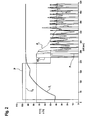
- the controller 16 uses only the threshold controller 22 to control the steam generator.
- the latter operates the steam generator 14 in the second heating stage 14.2, ie with a power of 100% (see the power curve P in the diagram).
- the controller 16 switches from the threshold value controller 22 to the PI controller 24 and uses this to control the steam generator 14. Accordingly, the value for the setpoint power HS S of the steam generator in the holding stage increases to a predetermined value of 75% of the power of the first heating stage (see curve HS S ).
- This value HS S is treated by the controller 16 as a buffer variable, based on which the steam generator 14 is now operated with the first heating stage 14.1 pulse width modulated.
- the controller 16 Since the maximum power of the steam generator is set here with 75% of the power of the first heating stage 14.1, the controller 16 switches on the first heating stage 14.1 of the steam generator 14 within a given time interval for 75% of the time and for 25% of the time, if the steam generator should be operated in the holding stage with maximum power. This is the case here as long as the setpoint H S for the holding stage remains at the value of 75%, that is to say just under 250 seconds. At this time, the PI controller 24 begins to regulate, as can be seen from the fluctuating values for the setpoint HS S of the hold stage.
- a continuous regulator in combination with a steam generator which is switched between two discrete power levels, can be used to keep the steam content in the cooking chamber comparatively constant.
- the regulator reaches a stable state after approximately 400 seconds.
- the power given by the PI controller 24 for the operation of the steam generator 14 in the holding stage can be represented by a multiplicity of very short heating pulses, between which correspondingly short switch-off times are used.
- electrically operated steam generators could by switching on and off of individual half-waves of the mains frequency the Heating power can be adjusted virtually infinitely. In this way one comes very close to an actually stepless control of the power, which would be advantageous in terms of control quality and energy consumption.
- FIG. 3 an embodiment is shown, which is characterized by a larger steam buffer 34.
- This is formed by the fact that the separating plate 32 is arranged closer to the exhaust pipe 30.
- the function of the separating plate 32 is to prevent a mixing of the steam with the air in the discharge region 26 as far as possible.
- the volume of the vapor buffer 34 defined with the separating plate 32 is at least as great as the vapor volume which can condense between two heating pulses in the cooking chamber 12. This ensures that air is not sucked in between two heating pulses, but steam from the steam buffer 34 (see the arrow D). Accordingly, the condensation device 28 must also be switched off at least between two heating pulses, so that steam can actually be stored in the vapor buffer 34.
- FIG. 4 an alternative embodiment is shown.
- this flow guide plates 36 are used, which extend in the longitudinal direction of the drain.
- the process can either have a circular cross section (see detail D1) or a box-shaped cross section (see detail D2).
- the Strömungsleitbleche 36 act as a vortex breaker, similar to the separating plate 32 prevent the air in the drain region 26 mixed with the existing steam there. Thus, as pure as possible vapor can be sucked back into the cooking space in the phases between two heating pulses. Due to the orientation of the flow guide plates 36 in the direction of the drainage channel, the flow in the longitudinal direction is hardly affected, but strongly suppressed in a direction transverse thereto.
- the flow baffles extending in the flow direction can all be mounted on the top of the drain. This makes it easier to rinse out soiling, so that no impurities can accumulate on the sheets.
Landscapes
- Engineering & Computer Science (AREA)
- Chemical & Material Sciences (AREA)
- Combustion & Propulsion (AREA)
- Mechanical Engineering (AREA)
- General Engineering & Computer Science (AREA)
- Cookers (AREA)
- Electric Ovens (AREA)
Applications Claiming Priority (1)
| Application Number | Priority Date | Filing Date | Title |
|---|---|---|---|
| DE102010045198A DE102010045198A1 (de) | 2010-09-13 | 2010-09-13 | Gargerät mit Dampfgenerator sowie Verfahren zur Regelung eines Dampfgenerators für ein Gargerät |
Publications (3)
| Publication Number | Publication Date |
|---|---|
| EP2428735A2 true EP2428735A2 (fr) | 2012-03-14 |
| EP2428735A3 EP2428735A3 (fr) | 2014-07-02 |
| EP2428735B1 EP2428735B1 (fr) | 2018-11-07 |
Family
ID=44675399
Family Applications (1)
| Application Number | Title | Priority Date | Filing Date |
|---|---|---|---|
| EP11007208.9A Active EP2428735B1 (fr) | 2010-09-13 | 2011-09-06 | Appareil de cuisson doté d'un générateur de vapeur et procédé de réglage d'un générateur de vapeur pour un appareil de cuisson |
Country Status (2)
| Country | Link |
|---|---|
| EP (1) | EP2428735B1 (fr) |
| DE (1) | DE102010045198A1 (fr) |
Cited By (1)
| Publication number | Priority date | Publication date | Assignee | Title |
|---|---|---|---|---|
| EP2745696A3 (fr) * | 2012-12-20 | 2017-01-04 | Miele & Cie. KG | Appareil de cuisson et procédé de fonctionnement d'un appareil de cuisson |
Family Cites Families (11)
| Publication number | Priority date | Publication date | Assignee | Title |
|---|---|---|---|---|
| DE1902063A1 (en) * | 1969-01-16 | 1970-08-13 | Philips Patentverwaltung Gmbh, 2000 Hamburg | Controlling oil or gas fired furnaces over - wide feed-ranges |
| DE2608295C2 (de) * | 1976-02-28 | 1982-11-18 | Brown, Boveri & Cie Ag, 6800 Mannheim | Elektronischer Temperaturregler zur Regelung der Energiezufuhr für ein elektrisches Heizelement |
| CH656204A5 (de) * | 1982-03-16 | 1986-06-13 | Schoenmann Wilfred Ernst | Dampfkessel mit elektrischer widerstandsheizung. |
| DE4223653C2 (de) * | 1992-07-17 | 2003-12-11 | Bsh Bosch Siemens Hausgeraete | Verfahren zum Regeln von Garvorgängen sowie dazugehöriger Backofen |
| DE4341410A1 (de) * | 1993-12-04 | 1995-06-08 | Licentia Gmbh | Back- und Bratofen mit einem Garraum und einem Dampferzeuger für den Garraum |
| DE10015747A1 (de) * | 2000-03-29 | 2001-10-04 | Bsh Bosch Siemens Hausgeraete | Dampfgargerät |
| US7049551B2 (en) * | 2004-09-30 | 2006-05-23 | Middleby Marshall, Inc. | Natural convection steam cooking device |
| US20060249137A1 (en) * | 2005-05-03 | 2006-11-09 | Malcolm Reay | System and method for draining water from a steam oven |
| US20070062927A1 (en) * | 2005-09-06 | 2007-03-22 | Sells Joel M | Steam generator system for a household oven |
| BRPI0705924A2 (pt) * | 2007-11-23 | 2009-07-21 | Whirlpool Sa | forno a gás para cozimento a vapor e fogão |
| DE102008056324B4 (de) * | 2008-11-07 | 2016-07-07 | Rational Ag | Verfahren zur Nachbefüllung eines Dampfgenerators mit Wasser, Dampfgenerator dafür und Gargerät damit |
-
2010
- 2010-09-13 DE DE102010045198A patent/DE102010045198A1/de not_active Ceased
-
2011
- 2011-09-06 EP EP11007208.9A patent/EP2428735B1/fr active Active
Non-Patent Citations (1)
| Title |
|---|
| None |
Cited By (1)
| Publication number | Priority date | Publication date | Assignee | Title |
|---|---|---|---|---|
| EP2745696A3 (fr) * | 2012-12-20 | 2017-01-04 | Miele & Cie. KG | Appareil de cuisson et procédé de fonctionnement d'un appareil de cuisson |
Also Published As
| Publication number | Publication date |
|---|---|
| DE102010045198A1 (de) | 2012-03-15 |
| EP2428735B1 (fr) | 2018-11-07 |
| EP2428735A3 (fr) | 2014-07-02 |
Similar Documents
| Publication | Publication Date | Title |
|---|---|---|
| EP1878309B1 (fr) | Procede et dispositif d'alimentation electrique de plusieurs bobines d'induction d'un appareil d'induction | |
| DE102004003126B4 (de) | Ansteuerungsverfahren für Heizelemente und Vorrichtung | |
| EP2697569B1 (fr) | Appareil de cuisson à la vapeur, en particulier four à vapeur | |
| EP3307018B1 (fr) | Procédé de commande d'une plaque de cuisson à induction et plaque de cuisson à induction | |
| EP2087770A1 (fr) | Procédé de commande d'un appareil de cuisson par induction, et appareil de cuisson par induction | |
| EP2390571A2 (fr) | Procédé de commande d'un brûleur à gaz et plaque de cuisson à gaz dotée de plusieurs brûleurs à gaz | |
| EP2904336A2 (fr) | Procédé de réglage d'un compresseur d'une installation frigorifique et installation frigorifique | |
| DE102011006736A1 (de) | Verfahren zum Ansteuern eines Gasbrenners und Steuereinrichtung für einen Gasbrenner | |
| EP2543285B1 (fr) | Dispositif de cuisson sous pression et procédé à exécuter | |
| EP2251607B1 (fr) | Procédé d'exécution d'un processus de préparation pour un aliment | |
| EP2428735B1 (fr) | Appareil de cuisson doté d'un générateur de vapeur et procédé de réglage d'un générateur de vapeur pour un appareil de cuisson | |
| EP3307019B1 (fr) | Procédé de fonctionnement d'un champ de cuisson à induction et champ de cuisson à induction | |
| CH682177A5 (fr) | ||
| DE102014216773B4 (de) | Verfahren zur Ansteuerung eines Gasventils in einem Gasgargerät und Gasgargerät | |
| DE102013214927B4 (de) | Verfahren zum Betrieb eines Gaskochfelds und Gaskochfeld | |
| DE202006016551U1 (de) | Induktionsheizeinrichtung | |
| DE10132304A1 (de) | Verfahren zum Betrieb eines Gargeräts sowie Gargerät | |
| DE102010036157B4 (de) | Verfahren zur Regelung einer Heizeinrichtung für ein Gargerät sowie Heizung für ein Gargerät | |
| DE102012200342B4 (de) | Verfahren zur Ansteuerung mehrerer Gasbrenner eines Gaskochfeldes | |
| DE102016222313B4 (de) | Verfahren zum Kochen von mindestens einem Ei | |
| DE102010030944A1 (de) | Verfahren zum Betrieb eines Gasbackofens und Gasbackofen | |
| EP1308619A1 (fr) | Turbine Pelton à injecteurs multiples | |
| EP3267114A1 (fr) | Procédé de commande d'un four de cuisson et four de cuisson | |
| DE102013215847A1 (de) | Verfahren zum Durchführen eines Zubereitungsvorgangs mit einer Absenk-Zeitdauer sowie Gargerät zum Durchführen eines derartigen Verfahrens | |
| EP3472514B1 (fr) | Procédé de fonctionnement d'un générateur de vapeur à récupération de chaleur |
Legal Events
| Date | Code | Title | Description |
|---|---|---|---|
| AK | Designated contracting states |
Kind code of ref document: A2 Designated state(s): AL AT BE BG CH CY CZ DE DK EE ES FI FR GB GR HR HU IE IS IT LI LT LU LV MC MK MT NL NO PL PT RO RS SE SI SK SM TR |
|
| AX | Request for extension of the european patent |
Extension state: BA ME |
|
| PUAI | Public reference made under article 153(3) epc to a published international application that has entered the european phase |
Free format text: ORIGINAL CODE: 0009012 |
|
| PUAL | Search report despatched |
Free format text: ORIGINAL CODE: 0009013 |
|
| AK | Designated contracting states |
Kind code of ref document: A3 Designated state(s): AL AT BE BG CH CY CZ DE DK EE ES FI FR GB GR HR HU IE IS IT LI LT LU LV MC MK MT NL NO PL PT RO RS SE SI SK SM TR |
|
| AX | Request for extension of the european patent |
Extension state: BA ME |
|
| RIC1 | Information provided on ipc code assigned before grant |
Ipc: F24C 7/08 20060101AFI20140528BHEP Ipc: F24C 15/32 20060101ALI20140528BHEP |
|
| 17P | Request for examination filed |
Effective date: 20141203 |
|
| RBV | Designated contracting states (corrected) |
Designated state(s): AL AT BE BG CH CY CZ DE DK EE ES FI FR GB GR HR HU IE IS IT LI LT LU LV MC MK MT NL NO PL PT RO RS SE SI SK SM TR |
|
| 17Q | First examination report despatched |
Effective date: 20160428 |
|
| STAA | Information on the status of an ep patent application or granted ep patent |
Free format text: STATUS: EXAMINATION IS IN PROGRESS |
|
| GRAP | Despatch of communication of intention to grant a patent |
Free format text: ORIGINAL CODE: EPIDOSNIGR1 |
|
| STAA | Information on the status of an ep patent application or granted ep patent |
Free format text: STATUS: GRANT OF PATENT IS INTENDED |
|
| INTG | Intention to grant announced |
Effective date: 20180517 |
|
| RAP1 | Party data changed (applicant data changed or rights of an application transferred) |
Owner name: RATIONAL AKTIENGESELLSCHAFT |
|
| GRAS | Grant fee paid |
Free format text: ORIGINAL CODE: EPIDOSNIGR3 |
|
| GRAA | (expected) grant |
Free format text: ORIGINAL CODE: 0009210 |
|
| STAA | Information on the status of an ep patent application or granted ep patent |
Free format text: STATUS: THE PATENT HAS BEEN GRANTED |
|
| AK | Designated contracting states |
Kind code of ref document: B1 Designated state(s): AL AT BE BG CH CY CZ DE DK EE ES FI FR GB GR HR HU IE IS IT LI LT LU LV MC MK MT NL NO PL PT RO RS SE SI SK SM TR |
|
| REG | Reference to a national code |
Ref country code: GB Ref legal event code: FG4D Free format text: NOT ENGLISH |
|
| REG | Reference to a national code |
Ref country code: CH Ref legal event code: EP Ref country code: AT Ref legal event code: REF Ref document number: 1062483 Country of ref document: AT Kind code of ref document: T Effective date: 20181115 |
|
| REG | Reference to a national code |
Ref country code: IE Ref legal event code: FG4D Free format text: LANGUAGE OF EP DOCUMENT: GERMAN |
|
| REG | Reference to a national code |
Ref country code: DE Ref legal event code: R096 Ref document number: 502011014952 Country of ref document: DE |
|
| REG | Reference to a national code |
Ref country code: NL Ref legal event code: MP Effective date: 20181107 |
|
| REG | Reference to a national code |
Ref country code: LT Ref legal event code: MG4D |
|
| PG25 | Lapsed in a contracting state [announced via postgrant information from national office to epo] |
Ref country code: LV Free format text: LAPSE BECAUSE OF FAILURE TO SUBMIT A TRANSLATION OF THE DESCRIPTION OR TO PAY THE FEE WITHIN THE PRESCRIBED TIME-LIMIT Effective date: 20181107 Ref country code: FI Free format text: LAPSE BECAUSE OF FAILURE TO SUBMIT A TRANSLATION OF THE DESCRIPTION OR TO PAY THE FEE WITHIN THE PRESCRIBED TIME-LIMIT Effective date: 20181107 Ref country code: NO Free format text: LAPSE BECAUSE OF FAILURE TO SUBMIT A TRANSLATION OF THE DESCRIPTION OR TO PAY THE FEE WITHIN THE PRESCRIBED TIME-LIMIT Effective date: 20190207 Ref country code: LT Free format text: LAPSE BECAUSE OF FAILURE TO SUBMIT A TRANSLATION OF THE DESCRIPTION OR TO PAY THE FEE WITHIN THE PRESCRIBED TIME-LIMIT Effective date: 20181107 Ref country code: BG Free format text: LAPSE BECAUSE OF FAILURE TO SUBMIT A TRANSLATION OF THE DESCRIPTION OR TO PAY THE FEE WITHIN THE PRESCRIBED TIME-LIMIT Effective date: 20190207 Ref country code: HR Free format text: LAPSE BECAUSE OF FAILURE TO SUBMIT A TRANSLATION OF THE DESCRIPTION OR TO PAY THE FEE WITHIN THE PRESCRIBED TIME-LIMIT Effective date: 20181107 Ref country code: ES Free format text: LAPSE BECAUSE OF FAILURE TO SUBMIT A TRANSLATION OF THE DESCRIPTION OR TO PAY THE FEE WITHIN THE PRESCRIBED TIME-LIMIT Effective date: 20181107 Ref country code: IS Free format text: LAPSE BECAUSE OF FAILURE TO SUBMIT A TRANSLATION OF THE DESCRIPTION OR TO PAY THE FEE WITHIN THE PRESCRIBED TIME-LIMIT Effective date: 20190307 |
|
| PG25 | Lapsed in a contracting state [announced via postgrant information from national office to epo] |
Ref country code: GR Free format text: LAPSE BECAUSE OF FAILURE TO SUBMIT A TRANSLATION OF THE DESCRIPTION OR TO PAY THE FEE WITHIN THE PRESCRIBED TIME-LIMIT Effective date: 20190208 Ref country code: NL Free format text: LAPSE BECAUSE OF FAILURE TO SUBMIT A TRANSLATION OF THE DESCRIPTION OR TO PAY THE FEE WITHIN THE PRESCRIBED TIME-LIMIT Effective date: 20181107 Ref country code: PT Free format text: LAPSE BECAUSE OF FAILURE TO SUBMIT A TRANSLATION OF THE DESCRIPTION OR TO PAY THE FEE WITHIN THE PRESCRIBED TIME-LIMIT Effective date: 20190307 Ref country code: RS Free format text: LAPSE BECAUSE OF FAILURE TO SUBMIT A TRANSLATION OF THE DESCRIPTION OR TO PAY THE FEE WITHIN THE PRESCRIBED TIME-LIMIT Effective date: 20181107 Ref country code: SE Free format text: LAPSE BECAUSE OF FAILURE TO SUBMIT A TRANSLATION OF THE DESCRIPTION OR TO PAY THE FEE WITHIN THE PRESCRIBED TIME-LIMIT Effective date: 20181107 Ref country code: AL Free format text: LAPSE BECAUSE OF FAILURE TO SUBMIT A TRANSLATION OF THE DESCRIPTION OR TO PAY THE FEE WITHIN THE PRESCRIBED TIME-LIMIT Effective date: 20181107 |
|
| PG25 | Lapsed in a contracting state [announced via postgrant information from national office to epo] |
Ref country code: CZ Free format text: LAPSE BECAUSE OF FAILURE TO SUBMIT A TRANSLATION OF THE DESCRIPTION OR TO PAY THE FEE WITHIN THE PRESCRIBED TIME-LIMIT Effective date: 20181107 Ref country code: PL Free format text: LAPSE BECAUSE OF FAILURE TO SUBMIT A TRANSLATION OF THE DESCRIPTION OR TO PAY THE FEE WITHIN THE PRESCRIBED TIME-LIMIT Effective date: 20181107 Ref country code: DK Free format text: LAPSE BECAUSE OF FAILURE TO SUBMIT A TRANSLATION OF THE DESCRIPTION OR TO PAY THE FEE WITHIN THE PRESCRIBED TIME-LIMIT Effective date: 20181107 |
|
| REG | Reference to a national code |
Ref country code: DE Ref legal event code: R097 Ref document number: 502011014952 Country of ref document: DE |
|
| PG25 | Lapsed in a contracting state [announced via postgrant information from national office to epo] |
Ref country code: EE Free format text: LAPSE BECAUSE OF FAILURE TO SUBMIT A TRANSLATION OF THE DESCRIPTION OR TO PAY THE FEE WITHIN THE PRESCRIBED TIME-LIMIT Effective date: 20181107 Ref country code: SM Free format text: LAPSE BECAUSE OF FAILURE TO SUBMIT A TRANSLATION OF THE DESCRIPTION OR TO PAY THE FEE WITHIN THE PRESCRIBED TIME-LIMIT Effective date: 20181107 Ref country code: SK Free format text: LAPSE BECAUSE OF FAILURE TO SUBMIT A TRANSLATION OF THE DESCRIPTION OR TO PAY THE FEE WITHIN THE PRESCRIBED TIME-LIMIT Effective date: 20181107 Ref country code: RO Free format text: LAPSE BECAUSE OF FAILURE TO SUBMIT A TRANSLATION OF THE DESCRIPTION OR TO PAY THE FEE WITHIN THE PRESCRIBED TIME-LIMIT Effective date: 20181107 |
|
| PLBE | No opposition filed within time limit |
Free format text: ORIGINAL CODE: 0009261 |
|
| STAA | Information on the status of an ep patent application or granted ep patent |
Free format text: STATUS: NO OPPOSITION FILED WITHIN TIME LIMIT |
|
| 26N | No opposition filed |
Effective date: 20190808 |
|
| PG25 | Lapsed in a contracting state [announced via postgrant information from national office to epo] |
Ref country code: SI Free format text: LAPSE BECAUSE OF FAILURE TO SUBMIT A TRANSLATION OF THE DESCRIPTION OR TO PAY THE FEE WITHIN THE PRESCRIBED TIME-LIMIT Effective date: 20181107 |
|
| PG25 | Lapsed in a contracting state [announced via postgrant information from national office to epo] |
Ref country code: TR Free format text: LAPSE BECAUSE OF FAILURE TO SUBMIT A TRANSLATION OF THE DESCRIPTION OR TO PAY THE FEE WITHIN THE PRESCRIBED TIME-LIMIT Effective date: 20181107 |
|
| PG25 | Lapsed in a contracting state [announced via postgrant information from national office to epo] |
Ref country code: MC Free format text: LAPSE BECAUSE OF FAILURE TO SUBMIT A TRANSLATION OF THE DESCRIPTION OR TO PAY THE FEE WITHIN THE PRESCRIBED TIME-LIMIT Effective date: 20181107 |
|
| REG | Reference to a national code |
Ref country code: CH Ref legal event code: PL |
|
| PG25 | Lapsed in a contracting state [announced via postgrant information from national office to epo] |
Ref country code: IE Free format text: LAPSE BECAUSE OF NON-PAYMENT OF DUE FEES Effective date: 20190906 Ref country code: CH Free format text: LAPSE BECAUSE OF NON-PAYMENT OF DUE FEES Effective date: 20190930 Ref country code: LU Free format text: LAPSE BECAUSE OF NON-PAYMENT OF DUE FEES Effective date: 20190906 Ref country code: LI Free format text: LAPSE BECAUSE OF NON-PAYMENT OF DUE FEES Effective date: 20190930 |
|
| REG | Reference to a national code |
Ref country code: BE Ref legal event code: MM Effective date: 20190930 |
|
| PG25 | Lapsed in a contracting state [announced via postgrant information from national office to epo] |
Ref country code: BE Free format text: LAPSE BECAUSE OF NON-PAYMENT OF DUE FEES Effective date: 20190930 |
|
| GBPC | Gb: european patent ceased through non-payment of renewal fee |
Effective date: 20190906 |
|
| PG25 | Lapsed in a contracting state [announced via postgrant information from national office to epo] |
Ref country code: FR Free format text: LAPSE BECAUSE OF NON-PAYMENT OF DUE FEES Effective date: 20190930 Ref country code: GB Free format text: LAPSE BECAUSE OF NON-PAYMENT OF DUE FEES Effective date: 20190906 |
|
| REG | Reference to a national code |
Ref country code: AT Ref legal event code: MM01 Ref document number: 1062483 Country of ref document: AT Kind code of ref document: T Effective date: 20190906 |
|
| PG25 | Lapsed in a contracting state [announced via postgrant information from national office to epo] |
Ref country code: AT Free format text: LAPSE BECAUSE OF NON-PAYMENT OF DUE FEES Effective date: 20190906 |
|
| PG25 | Lapsed in a contracting state [announced via postgrant information from national office to epo] |
Ref country code: CY Free format text: LAPSE BECAUSE OF FAILURE TO SUBMIT A TRANSLATION OF THE DESCRIPTION OR TO PAY THE FEE WITHIN THE PRESCRIBED TIME-LIMIT Effective date: 20181107 |
|
| PG25 | Lapsed in a contracting state [announced via postgrant information from national office to epo] |
Ref country code: MT Free format text: LAPSE BECAUSE OF FAILURE TO SUBMIT A TRANSLATION OF THE DESCRIPTION OR TO PAY THE FEE WITHIN THE PRESCRIBED TIME-LIMIT Effective date: 20181107 Ref country code: HU Free format text: LAPSE BECAUSE OF FAILURE TO SUBMIT A TRANSLATION OF THE DESCRIPTION OR TO PAY THE FEE WITHIN THE PRESCRIBED TIME-LIMIT; INVALID AB INITIO Effective date: 20110906 |
|
| PG25 | Lapsed in a contracting state [announced via postgrant information from national office to epo] |
Ref country code: MK Free format text: LAPSE BECAUSE OF FAILURE TO SUBMIT A TRANSLATION OF THE DESCRIPTION OR TO PAY THE FEE WITHIN THE PRESCRIBED TIME-LIMIT Effective date: 20181107 |
|
| P01 | Opt-out of the competence of the unified patent court (upc) registered |
Effective date: 20230522 |
|
| PGFP | Annual fee paid to national office [announced via postgrant information from national office to epo] |
Ref country code: DE Payment date: 20250919 Year of fee payment: 15 |
|
| PGFP | Annual fee paid to national office [announced via postgrant information from national office to epo] |
Ref country code: IT Payment date: 20250930 Year of fee payment: 15 |