EP2429042A1 - Fahrzeugladestecker - Google Patents
Fahrzeugladestecker Download PDFInfo
- Publication number
- EP2429042A1 EP2429042A1 EP11005829A EP11005829A EP2429042A1 EP 2429042 A1 EP2429042 A1 EP 2429042A1 EP 11005829 A EP11005829 A EP 11005829A EP 11005829 A EP11005829 A EP 11005829A EP 2429042 A1 EP2429042 A1 EP 2429042A1
- Authority
- EP
- European Patent Office
- Prior art keywords
- vehicle
- connector
- charging connector
- lock
- unlock operation
- Prior art date
- Legal status (The legal status is an assumption and is not a legal conclusion. Google has not performed a legal analysis and makes no representation as to the accuracy of the status listed.)
- Withdrawn
Links
- XLYOFNOQVPJJNP-UHFFFAOYSA-N water Substances O XLYOFNOQVPJJNP-UHFFFAOYSA-N 0.000 claims abstract description 82
- 230000008878 coupling Effects 0.000 claims abstract description 16
- 238000010168 coupling process Methods 0.000 claims abstract description 16
- 238000005859 coupling reaction Methods 0.000 claims abstract description 16
- 230000002452 interceptive effect Effects 0.000 description 3
- 238000010008 shearing Methods 0.000 description 3
- 230000015572 biosynthetic process Effects 0.000 description 2
- 230000002093 peripheral effect Effects 0.000 description 2
- 230000008014 freezing Effects 0.000 description 1
- 238000007710 freezing Methods 0.000 description 1
- 239000002184 metal Substances 0.000 description 1
- 238000000465 moulding Methods 0.000 description 1
- 238000005192 partition Methods 0.000 description 1
- 238000000638 solvent extraction Methods 0.000 description 1
- 229920003002 synthetic resin Polymers 0.000 description 1
- 239000000057 synthetic resin Substances 0.000 description 1
- 210000003813 thumb Anatomy 0.000 description 1
Images






Classifications
-
- H—ELECTRICITY
- H01—ELECTRIC ELEMENTS
- H01R—ELECTRICALLY-CONDUCTIVE CONNECTIONS; STRUCTURAL ASSOCIATIONS OF A PLURALITY OF MUTUALLY-INSULATED ELECTRICAL CONNECTING ELEMENTS; COUPLING DEVICES; CURRENT COLLECTORS
- H01R13/00—Details of coupling devices of the kinds covered by groups H01R12/70 or H01R24/00 - H01R33/00
- H01R13/46—Bases; Cases
- H01R13/52—Dustproof, splashproof, drip-proof, waterproof, or flameproof cases
- H01R13/5227—Dustproof, splashproof, drip-proof, waterproof, or flameproof cases with evacuation of penetrating liquids
-
- B—PERFORMING OPERATIONS; TRANSPORTING
- B60—VEHICLES IN GENERAL
- B60L—PROPULSION OF ELECTRICALLY-PROPELLED VEHICLES; SUPPLYING ELECTRIC POWER FOR AUXILIARY EQUIPMENT OF ELECTRICALLY-PROPELLED VEHICLES; ELECTRODYNAMIC BRAKE SYSTEMS FOR VEHICLES IN GENERAL; MAGNETIC SUSPENSION OR LEVITATION FOR VEHICLES; MONITORING OPERATING VARIABLES OF ELECTRICALLY-PROPELLED VEHICLES; ELECTRIC SAFETY DEVICES FOR ELECTRICALLY-PROPELLED VEHICLES
- B60L53/00—Methods of charging batteries, specially adapted for electric vehicles; Charging stations or on-board charging equipment therefor; Exchange of energy storage elements in electric vehicles
- B60L53/10—Methods of charging batteries, specially adapted for electric vehicles; Charging stations or on-board charging equipment therefor; Exchange of energy storage elements in electric vehicles characterised by the energy transfer between the charging station and the vehicle
- B60L53/14—Conductive energy transfer
- B60L53/16—Connectors, e.g. plugs or sockets, specially adapted for charging electric vehicles
-
- H—ELECTRICITY
- H01—ELECTRIC ELEMENTS
- H01R—ELECTRICALLY-CONDUCTIVE CONNECTIONS; STRUCTURAL ASSOCIATIONS OF A PLURALITY OF MUTUALLY-INSULATED ELECTRICAL CONNECTING ELEMENTS; COUPLING DEVICES; CURRENT COLLECTORS
- H01R13/00—Details of coupling devices of the kinds covered by groups H01R12/70 or H01R24/00 - H01R33/00
- H01R13/62—Means for facilitating engagement or disengagement of coupling parts or for holding them in engagement
- H01R13/627—Snap or like fastening
- H01R13/6275—Latching arms not integral with the housing
-
- B—PERFORMING OPERATIONS; TRANSPORTING
- B60—VEHICLES IN GENERAL
- B60L—PROPULSION OF ELECTRICALLY-PROPELLED VEHICLES; SUPPLYING ELECTRIC POWER FOR AUXILIARY EQUIPMENT OF ELECTRICALLY-PROPELLED VEHICLES; ELECTRODYNAMIC BRAKE SYSTEMS FOR VEHICLES IN GENERAL; MAGNETIC SUSPENSION OR LEVITATION FOR VEHICLES; MONITORING OPERATING VARIABLES OF ELECTRICALLY-PROPELLED VEHICLES; ELECTRIC SAFETY DEVICES FOR ELECTRICALLY-PROPELLED VEHICLES
- B60L2270/00—Problem solutions or means not otherwise provided for
- B60L2270/30—Preventing theft during charging
- B60L2270/32—Preventing theft during charging of electricity
-
- B—PERFORMING OPERATIONS; TRANSPORTING
- B60—VEHICLES IN GENERAL
- B60L—PROPULSION OF ELECTRICALLY-PROPELLED VEHICLES; SUPPLYING ELECTRIC POWER FOR AUXILIARY EQUIPMENT OF ELECTRICALLY-PROPELLED VEHICLES; ELECTRODYNAMIC BRAKE SYSTEMS FOR VEHICLES IN GENERAL; MAGNETIC SUSPENSION OR LEVITATION FOR VEHICLES; MONITORING OPERATING VARIABLES OF ELECTRICALLY-PROPELLED VEHICLES; ELECTRIC SAFETY DEVICES FOR ELECTRICALLY-PROPELLED VEHICLES
- B60L2270/00—Problem solutions or means not otherwise provided for
- B60L2270/30—Preventing theft during charging
- B60L2270/34—Preventing theft during charging of parts
-
- H—ELECTRICITY
- H01—ELECTRIC ELEMENTS
- H01R—ELECTRICALLY-CONDUCTIVE CONNECTIONS; STRUCTURAL ASSOCIATIONS OF A PLURALITY OF MUTUALLY-INSULATED ELECTRICAL CONNECTING ELEMENTS; COUPLING DEVICES; CURRENT COLLECTORS
- H01R2201/00—Connectors or connections adapted for particular applications
- H01R2201/26—Connectors or connections adapted for particular applications for vehicles
-
- Y—GENERAL TAGGING OF NEW TECHNOLOGICAL DEVELOPMENTS; GENERAL TAGGING OF CROSS-SECTIONAL TECHNOLOGIES SPANNING OVER SEVERAL SECTIONS OF THE IPC; TECHNICAL SUBJECTS COVERED BY FORMER USPC CROSS-REFERENCE ART COLLECTIONS [XRACs] AND DIGESTS
- Y02—TECHNOLOGIES OR APPLICATIONS FOR MITIGATION OR ADAPTATION AGAINST CLIMATE CHANGE
- Y02T—CLIMATE CHANGE MITIGATION TECHNOLOGIES RELATED TO TRANSPORTATION
- Y02T10/00—Road transport of goods or passengers
- Y02T10/60—Other road transportation technologies with climate change mitigation effect
- Y02T10/70—Energy storage systems for electromobility, e.g. batteries
-
- Y—GENERAL TAGGING OF NEW TECHNOLOGICAL DEVELOPMENTS; GENERAL TAGGING OF CROSS-SECTIONAL TECHNOLOGIES SPANNING OVER SEVERAL SECTIONS OF THE IPC; TECHNICAL SUBJECTS COVERED BY FORMER USPC CROSS-REFERENCE ART COLLECTIONS [XRACs] AND DIGESTS
- Y02—TECHNOLOGIES OR APPLICATIONS FOR MITIGATION OR ADAPTATION AGAINST CLIMATE CHANGE
- Y02T—CLIMATE CHANGE MITIGATION TECHNOLOGIES RELATED TO TRANSPORTATION
- Y02T10/00—Road transport of goods or passengers
- Y02T10/60—Other road transportation technologies with climate change mitigation effect
- Y02T10/7072—Electromobility specific charging systems or methods for batteries, ultracapacitors, supercapacitors or double-layer capacitors
-
- Y—GENERAL TAGGING OF NEW TECHNOLOGICAL DEVELOPMENTS; GENERAL TAGGING OF CROSS-SECTIONAL TECHNOLOGIES SPANNING OVER SEVERAL SECTIONS OF THE IPC; TECHNICAL SUBJECTS COVERED BY FORMER USPC CROSS-REFERENCE ART COLLECTIONS [XRACs] AND DIGESTS
- Y02—TECHNOLOGIES OR APPLICATIONS FOR MITIGATION OR ADAPTATION AGAINST CLIMATE CHANGE
- Y02T—CLIMATE CHANGE MITIGATION TECHNOLOGIES RELATED TO TRANSPORTATION
- Y02T90/00—Enabling technologies or technologies with a potential or indirect contribution to GHG emissions mitigation
- Y02T90/10—Technologies relating to charging of electric vehicles
- Y02T90/14—Plug-in electric vehicles
Definitions
- the present disclosure relates to a vehicle charging connector adapted to be coupled to a vehicle-side connector to charge a vehicle battery.
- a related art vehicle charging connector has a housing and a coupling portion arranged at a front opening of the housing.
- the coupling portion is adapted to be coupled to a vehicle-side connector.
- a lever is arranged to extend in a front-rear direction of the charging connector.
- the lever has a lever bar, a lock portion disposed on the front end of the lever bar, and an unlock operation portion disposed on the rear end of the lever bar.
- the vehicle-side connector has a lock receiving portion engageable with the lock portion of the lever.
- the charging connector When charging the vehicle battery, the charging connector is coupled to the vehicle-side connector such that the lock portion and the lock receiving portion engage with each other, whereby the charging connector and the vehicle-side connector are maintained in a firmly fitted condition.
- the unlock operation portion is pressed to release the lock portion from the lock receiving portion, so that the charging connector can be decoupled from the vehicle-side connector (see, e.g., JP 2010-123521 A ).
- the charging connector when the charging connector is, for example, used outdoors and exposed to cold temperature, water may enter the housing and freeze on an upper surface of the lever bar, and the resulting ice on the lever bar may grow due to subsequent waterdrops adhering to the ice, in which case the ice may interfere with the unlock operation of the lever, for example, by hitting an inner wall of the housing. Further, to remove the ice, the housing may need to be disassembled.
- Illustrative aspects of the present invention have been made with a view to preventing a lock or unlock operation of a vehicle charging connector from being obstructed by ice.
- An illustrative aspect of the present invention provides a vehicle charging connector configured to be coupled to a vehicle-side connector to charge a vehicle battery via the vehicle-side connector.
- the vehicle charging connector includes a housing, a coupling portion provided on the housing and configured to be coupled to the vehicle-side connector, and a lever.
- the lever has a lever bar accommodated in the housing, a lock portion provided on one end of the lever bar and configured to engage with a lock receiving portion of the vehicle-side connector to maintain the coupling portion and the vehicle-side connector in a coupled condition, and an unlock operation portion provided on the other end of the lever bar and operable to release an engagement between the lock portion and the lock receiving portion.
- An upper surface of the lever bar includes a water guide adjacent to the lock portion.
- the water guide includes a slope surface having a downward inclination.
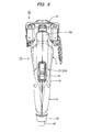
- a vehicle charging connector 10 has a shape like a handgun as a whole.
- the charging connector 10 includes a connector main body 11 forming about a front half of the charging connector 10 and a grip 12 extending obliquely downward from a rear end of the connector main body 11.
- the connector main body 11 and the grip 12 are made of a synthetic resin as a one-piece structure to form a housing.
- a cylindrical coupling portion 13 is arranged to protrude forward from a front end of the connector main body 11. Inside the connector main body 11, as shown in FIG. 4 , a lever bar 21 of a lever 20 is accommodated.
- the coupling portion 13 is formed as a separate member from the connector main body 11, and is fixed to the front end of the connector main body 11. Inside the coupling portion 13, a plurality of cylindrical terminal covers 14 are provided. The terminal covers 14 are provided to protrude forward from a base wall of the coupling portion 13. Each of the terminal covers 14 is formed with a cavity to accommodate an associated terminal fitting therein.
- a plurality of electric wires W extends from a rear side of coupling portion 13.
- the wires W are arranged to extend through the connector main body 11 to the inside of the grip 12 where the wires W are bundled by a sheath to form a single cable W1.
- the cable W1 is fixed inside of the grip 12 by a wire holding ring or the like, and is also fixed at a rear end of the grip 12 by a bush 40.
- the bush 40 is tightly attached to an inner circumferential surface of a rear opening portion of the grip 12 and to an outer circumferential surface of the cable W1, so as to prevent water from entering into the grip 12 from the rear end of the grip 12. Further, drain holes 15 are formed though the bottom walls of the connector main body 11 and the grip 12. Therefore, even when water enters into the connector main body 11 or the grip 12, it is possible to drain the water to the outside from the drain holes 15.
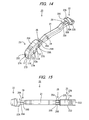
- the lever 20 includes a lever bar 21 extending in a front-rear direction of the charging connector 10, a lock portion 22 disposed on the front end of the lever bar 21, and an unlock operation portion 23 disposed on the rear end of the lever bar 21.
- a pivot 24 is provided at an approximately center portion of the lever bar 21 in the front-rear direction. The pivot 24 is rotatably supported inside the connector main body 11 so that the front and rear end portions of the lever bar 21 can tilt on the pivot 24 like a seesaw.
- the lever bar 21 extends horizontally, then extends slightly obliquely upward, and extends horizontally again.
- the lever bar 21 extends obliquely downward. Therefore, the lock portion 22 is disposed at an upper position than the unlock operation portion 23.
- a portion of the connector main body 11, along which the lever 20 is arranged, is bulged upward, and a front end portion of the bulged portion serves a protection wall 11A.
- the protection wall 11 A is provided to protrude forward from the other portion of the connector main body 11 such that the front end portion of the lever bar 21 is covered by the protection wall 11A with the lock portion 22 being exposed to the outside. Therefore, when the charging connector 10 is erroneously dropped, the lever bar 21 can be prevented from being damaged.
- the lock portion 22 includes a head 22A protruding upward from a horizontal portion of the front end portion of the lever bar 21 and a locking protrusion 22B protruding downward from the horizontal portion of the front end portion of the lever bar 21.
- the locking protrusion 22B is in an overhung manner such that the locking protrusion 22B extends rearward as it extends downward.
- a lock receiving protrusion 52 of the vehicle side connector 50, with which the locking protrusion 22B engages is formed in a corresponding overhung manner, as shown in FIG. 4 .
- the lock receiving protrusion 52 is reinforced by covering its surface by a metal plate.
- the lock receiving protrusion 52 is an example of a lock receiving portion, and the lock receiving portion may not necessarily be in a form of a protrusion as long as the locking protrusion 22B is engageable with the lock receiving portion.
- the head 22A is formed to become wider as it extends upward. This it to ensure the strength that can withstand an impact when the charging connector 10 is erroneously dropped and the head 22A directly hits the ground.
- a rear surface 22C of the head 22A is arranged to face the housing, and is formed in a overhung manner such that the rear surface 22C extends rearward as extends upward.
- the lock portion 22 is disposed outside the front opening of the connector main body 11, in front of the protection wall 11 A.
- a front end of the upper portion of the connector main body 11 i.e., the front end of the protection wall 11 A
- the top surface of the connector main body 11 is disposed substantially on the same plane as the top surface of the head 22A.
- the rear surface 22C of the lock portion 22 extends in the vertical direction. Therefore, it is possible to prevent water from remaining and freezing in a space between the rear surface 22C of the lock portion 22 and the protection wall 11 A.
- the vehicle-side connector 50 is attached to a vehicle body in a slightly upward orientation. Accordingly, when the charging connector 10 is coupled to the vehicle-side connector 50, the charging connector 10 oriented slightly downward. Therefore, the rear surface 22C of the head 22A is arranged to extend substantially in the vertical direction when the charging connector 10 is coupled to the vehicle-side connector 50. In other words, the rear surface 22C of the head 22A is arranged to extend upward in a direction away from the vehicle-side connector 50 with respect a plane perpendicular to the coupling direction of the connectors 10, 50.
- snow on the head 22A may melt and the resulting water may enter between the rear surface 22C of the head 22A and the protection wall 11A.
- the rear surface 22C of the head 22A vertically extends when the charging connector 10 is coupled to the vehicle-side connector 50, the water does no remain on the rear surface 22C of the head 22A, and is prevented from being frozen between the rear surface 22C of the head 22A and the protection wall 11A, thereby avoiding a situation in which the lock portion 22 cannot be released from the lock receiving protrusion 52.
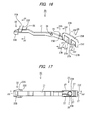
- the unlock operation portion 23 is arranged to protrude out from an opening 16 formed though a rear portion of the upper wall of the connector main body 11. As shown in FIG. 16 , the unlock operation portion 23 is formed to protrude upward from the rear end of the lever bar 21.
- the unlock operation portion 23 has a pressing surface 23A extending obliquely downward, a pair of side surfaces 23B extending downward from respective lateral sides of the pressing surface 23A, and a rear surface 23C extending downward from a rear side of the pressing surface 23A.
- the unlock operation portion 23 further has a spring receiving section 25 formed in the bottom of the unlock operation portion 23 to receive an upper end of a coil spring 60.
- a spring mounting base 17 is provided to support a lower end of the coil spring 60.
- the coil spring 60 is mounted between the spring receiving section 25 and the spring mounting base 17 in a compressed manner such that the coil spring 60 pushes the rear end of the lever bar 21 upward to keep the lock portion 22 in a locking position shown in FIG. 4 .
- the lock portion 22 is lifted up so as to be displaced in a release position shown in FIG. 6 .
- water may fall on the upper surface of the lever bar 21 through the space between the rear surface 22C of the head 22A and the front surface of the protection wall 11A. If the water forms into ice on the upper surface of the lever bar 21, the ice may interfere with the inner wall of the protection wall 11A and prevent the lock portion 22 from moving from the locking position to the release position.
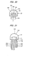
- a water guide 26 is provided on the front end portion (the end portion adjacent to the lock portion 22) of the upper surface of the lever bar 21, so that the water falling on the water guide 26 runs down toward a region below the lever bar 21.
- the water guide 26 has a pair of flat slope surfaces 26A.
- the slope surfaces 26A have a downward inclination extending obliquely downward from a vertex 26B at the center in the width direction of the water guide 26, and are disposed in a bilaterally symmetric manner. Because the slope surfaces 26A are flat, it is possible to smoothly guide and remove the water downward.
- the unlock operation portion 23 for example, water may enter a gap between the side surfaces 23B and a circumferential edge of the opening 16 that faces the side surfaces 23B, and the water may remain in the gap between the side surfaces 23B and the circumferential edge of the opening 16 due to its surface tension. If the water between the side surfaces 23B and the circumferential edge of the opening 16 freezes, the resulting ice prevents the unlock operation portion 23 from being pressed down. This may also occur in a gap between a front surface 23D of the unlock operation portion 23 the circumferential edge of the opening 16 or in a gap between the rear surface 23C and the circumferential edge of the opening 16.
- a plurality of recesses 27 are formed on the side surfaces 23B of the unlock operation portion 23.
- the recesses 27 are provided to face the circumferential edge of the opening 16.
- upper edges 27A of the recesses 27 are above the circumferential edge of the opening 16.
- the distance from the recesses 27 to the circumferential edge of the opening 16 is longer than the distance from the other portions of the side surfaces 23B to the circumferential edge of the opening 16.
- the influence of the surface tension is reduced at the recesses 27. Therefore, the water smoothly runs down through the recesses 27, so that water is prevented from being frozen in the recesses 27 and from interfering with the unlock operation.
- a recess 27 is formed on the rear surface 23C.
- the recesses 27 are arranged in the front-rear direction in a pair.
- Step surfaces substantially perpendicular to the side surface 23B form peripheral edges of each of the recesses 27.
- the front edge and the rear edge of the recess 27 extend vertically, parallel to each another.
- the upper edge 27A of the recess 27 extend obliquely downward toward the rear surface 23C, substantially parallel to the pressing surface 23A of the unlock operation portion 23.
- Peripheral edges of the recess 27 on the rear surface 23C are likewise formed by step surfaces that are substantially perpendicular to the rear surface 23C.
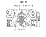
- the ice can be fractured by shearing. That is, when the unlock operation portion 23 is pressed, the upper edges 27A of the recesses 27 enter the opening 16 as shown in FIGS. 11 and 13 , such that the upper edges 27A of the recesses 27 and the circumferential edge of the opening 16 serve as shearing edges. Therefore, even when ice is formed in the recesses 27, the ice can be easily fractured by the upper edges 27A of the recesses 27.
- a recess is not formed on the front surface 23D of the unlock operation portion 23.
- the lever bar 21 and the front surface 23D of the unlock operation portion 23 are arranged to face each other in a V-shaped manner, which would require a slide mold to form a recess in the front surface 23D of the unlock operation portion 23, making a mold complex and increasing molding cost.
- the front surface 23D of the unlock operation portion 23 and the circumferential edge of the opening 16 are arranged such that the water entering a gap between the front surface 23D of the unlock operation portion 23 and the circumferential edge of the opening 16 runs though the gap and falls on the upper surface of the lever bar 21. That is, the gap between the front surface 23D of the unlock operation portion 23 and the circumferential edge of the opening 16 is set so that the surface tension is sufficiently small to allow the water to pass through.
- a water guide 28 is provided on an upper surface of an end portion of the lever bar 21 adjacent to the unlock operation portion 23.
- the water guide 28 a similar configuration as the water guide 26, and has a pair of slope surfaces 28A. That is, as shown in FIG. 23 , the slope surfaces 28A have a downward inclination extending obliquely downward from a vertex 28B at the center in the width direction of the water guide 28, and are disposed in a bilaterally symmetric manner. Therefore, as shown in FIG. 12 , the water falling on the water guide 28 runs down and is smoothly removed toward a region below the lever bar 21.
- a water catching wall 18 is formed around the circumferential edge of the opening 16.
- the water catching wall 18 has an inclined surface 18A extending downward from the side surfaces 23B of the unlock operation portion 23.
- the inclined surface 18A is steeply inclined.
- the water catching wall 18 is provided around the entire periphery of the opening 16. When the water is attached to the side surfaces 23B of the unlock operation portion 23, the water is directed toward the water catching wall 18 by the inclined surface 18A. Therefore, it is possible to reduce the water entering the gap between the unlock operation portion 23 and the circumferential edge of the opening 16.
- the lock portion 22 moves onto the lock receiving protrusion 52 and the lever 20 is tilted accordingly.
- the connectors 10, 50 are completely coupled to each other, and at the same time, the lock portion 22 that has moved over the lock receiving protrusion 52 returns elastically and engages with the lock receiving protrusion 52 in the coupled direction. In this way, the coupled condition of the connectors 10, 50 is locked.
- a battery is charged while the connectors 10, 50 are being coupled, and when the charging is finished, the grip 12 is grasped by a user's hand and the pressing surface 23A of the unlock operation portion 23 is pressed by a thumb.
- the water when water enters the gap between the lock portion 22 and the connector main body 11, the water falls on the water guide 26. However, the water runs down along the slope surfaces 26A and is removed to a region below the lever bar 21. Further, when water is attached to the unlock operation portion 23, the water is directed toward the water catching wall 18 by the inclined surface 18A of the water catching wall 18, and runs along the outer circumferential surface of the connector main body 11. Thus, the water is controlled so as not to enter into the connector main body 11 from the opening 16.
- the water attached to the unlock operation portion 23 may enter the recesses 27. However, in this case, the water runs down to lower edges 27B of the recesses 27 and falls, so that the water is drained out from the connector main body 11 through the drain holes 15. Even if ice is formed in the recesses 27, the ice is destroyed between the upper edges 27A of the recesses 27 and the circumferential edge of the opening 16 by shearing when pressing the unlock operation portion 23.
- the water guide 26 is provided on the upper surface of the end portion of the lever bar 21 adjacent to the lock portion 22.
- the water guide 26 includes a pair of slope surfaces 26A, the water can smoothly run down toward the lower side of the lever bar 21 along the two slope surfaces 26A.
- the rear surface 22C of the lock portion 22 is formed in the overhang form.
- the recesses 27 are provided in the side surfaces 23B and the rear surface 23C of the unlock operation portion 23. Therefore, water can smoothly run down through the recesses 27. That is, it is possible to prevent water from remaining in a gap between the unlock operation portion 23 and the circumferential edge of the opening 16. Further, water attached to the unlock operation portion 23 is directed toward the water catching wall 18 by the inclined surface 18A. This reduces the likelihood of the water entering the gap between the unlock operation portion 23 and the circumferential edge of the opening 16. Furthermore, water entering a gap between the front surface 23D of the unlock operation portion 23 and the circumferential edge of the opening 16 falls on the water guide 28, but this water runs down along the slope surfaces 28A. Therefore, it is possible to prevent the unlock operation from being obstructed due to the ice formation near the unlock operation portion 23.
- the present invention is not limited to the exemplary embodiment described above and, for example, the technical scope of the present invention includes the following exemplary embodiments.
- the slope surfaces 26A of the water guide 26 may not be flat, and may be an curved slope surface.
- the number of slope surfaces 26A of the water guide 26 is not limited to two, and may be one, or three or more.
- the recesses 27 may not be provided on all of the side surfaces 23B and the rear surface 23C of the unlock operation portion 23, and may be provided only on the side surfaces 23B or on the rear surface 23C. Further, the number of recesses 27 on each of the side surfaces 23B is not limited to two. For example, a single recess may be provided over the substantially entire area of the side surface 23B. Alternatively, three or more recesses may be formed on the side surface 23B. In this case, it is advantages to narrow the width of each of a partition walls partitioning the recesses as much as possible.
- the water catching wall 18 may not be provided along the entire periphery of the circumferential edge of the opening 16.
- the water catching wall may be provided only at portions of the circumferential edge of the opening 16 not facing the recesses 27.
- the water catching wall 18 may not include the inclined surface 18A.
- the water catching wall may be surface treated to have high water absorbing property.
- a recess may be formed on the front surface 23D of the unlock operation portion 23 when, for example, the front surface 23D and the upper surface of the lever bar 21 is arranged such that the recess can be formed on the front surface 23D without using a slide mold.
- the water guide 28 may not be provided.
- the inclination angle of the rear surface 22C of the lock portion 22 is not limited to the angle in the exemplary embodiment, and may be suitably set in accordance with an inclination the connectors 10, 50 in a coupled condition.
Landscapes
- Engineering & Computer Science (AREA)
- Power Engineering (AREA)
- Transportation (AREA)
- Mechanical Engineering (AREA)
- Electric Propulsion And Braking For Vehicles (AREA)
- Connector Housings Or Holding Contact Members (AREA)
- Details Of Connecting Devices For Male And Female Coupling (AREA)
Applications Claiming Priority (1)
| Application Number | Priority Date | Filing Date | Title |
|---|---|---|---|
| JP2010202236A JP5197699B2 (ja) | 2010-09-09 | 2010-09-09 | 充電用コネクタ |
Publications (1)
| Publication Number | Publication Date |
|---|---|
| EP2429042A1 true EP2429042A1 (de) | 2012-03-14 |
Family
ID=44514328
Family Applications (1)
| Application Number | Title | Priority Date | Filing Date |
|---|---|---|---|
| EP11005829A Withdrawn EP2429042A1 (de) | 2010-09-09 | 2011-07-15 | Fahrzeugladestecker |
Country Status (4)
| Country | Link |
|---|---|
| US (1) | US8152550B2 (de) |
| EP (1) | EP2429042A1 (de) |
| JP (1) | JP5197699B2 (de) |
| CN (1) | CN102403616A (de) |
Families Citing this family (39)
| Publication number | Priority date | Publication date | Assignee | Title |
|---|---|---|---|---|
| JP5471890B2 (ja) | 2010-06-28 | 2014-04-16 | 住友電装株式会社 | 充電用コネクタ |
| US8197277B1 (en) * | 2010-12-23 | 2012-06-12 | Itt Manufacturing Enterprises, Inc. | Charger connector |
| US8834202B2 (en) | 2011-06-13 | 2014-09-16 | Lear Corporation | Connector assembly for vehicle charging |
| USD702656S1 (en) * | 2011-07-05 | 2014-04-15 | Sumitomo Wiring Systems, Ltd. | Charging connector for an automobile |
| USD702641S1 (en) * | 2011-07-05 | 2014-04-15 | Sumitomo Wiring Systems, Ltd. | Charging connector for an automobile |
| USD702649S1 (en) * | 2011-07-05 | 2014-04-15 | Sumitomo Wiring Systems, Ltd. | Charging connector for an automobile |
| USD702648S1 (en) * | 2011-07-05 | 2014-04-15 | Sumitomo Wiring Systems, Ltd. | Charging connector for an automobile |
| USD700143S1 (en) * | 2011-07-05 | 2014-02-25 | Sumitomo Wiring Systems, Ltd. | Charging connector for an automobile |
| US9793642B2 (en) * | 2011-08-22 | 2017-10-17 | Lear Corporation | Connector assembly |
| JP5798935B2 (ja) * | 2012-01-17 | 2015-10-21 | 矢崎総業株式会社 | 電気コネクタ |
| WO2014007019A1 (ja) * | 2012-07-05 | 2014-01-09 | 日産自動車株式会社 | 電動車両の充電ポート装置 |
| JPWO2014010337A1 (ja) * | 2012-07-09 | 2016-06-20 | 日産自動車株式会社 | 電動車両の充電ポート装置 |
| JP5939927B2 (ja) * | 2012-08-06 | 2016-06-22 | 矢崎総業株式会社 | 充電コネクタ |
| JP2014086338A (ja) * | 2012-10-25 | 2014-05-12 | Yazaki Corp | 充電コネクタ |
| US9277191B2 (en) | 2012-12-12 | 2016-03-01 | Schneider Electric USA, Inc. | Security monitoring systems, methods and devices for electric vehicle charging stations |
| WO2014116600A1 (en) * | 2013-01-22 | 2014-07-31 | Hypertronics Corporation | Coupling system including a receptacle housing with a rotating domed door |
| JP6092662B2 (ja) * | 2013-03-05 | 2017-03-08 | 矢崎総業株式会社 | 充電コネクタ |
| EP2980926B1 (de) * | 2013-03-28 | 2017-11-01 | Yazaki Corporation | Ladestecker |
| DE102015101265A1 (de) * | 2015-01-29 | 2016-08-04 | Phoenix Contact E-Mobility Gmbh | Steckverbinder |
| DE102015114138B4 (de) * | 2015-08-26 | 2022-05-25 | Phoenix Contact E-Mobility Gmbh | Steckverbinderteil mit einem Verriegelungselement |
| USD795193S1 (en) * | 2015-12-17 | 2017-08-22 | Suzhou Recodeal Interconnect System Co.,Ltd. | AC coupler of electric vehicles |
| JP2017220388A (ja) * | 2016-06-09 | 2017-12-14 | 住友電装株式会社 | 充電用コネクタ |
| US20190267758A1 (en) * | 2016-11-30 | 2019-08-29 | Lg Innotek Co., Ltd. | Electricity charging plug device, electricity charging connection device, electricity charging device and electric vehicle |
| US10249992B2 (en) * | 2017-01-23 | 2019-04-02 | Eaton Intelligent Power Limited | Electric vehicle charging handle, light pipe therefor, and associated light visibility enhancing method |
| JP6704363B2 (ja) * | 2017-02-01 | 2020-06-03 | 株式会社城南製作所 | 充電コネクタ用ロック装置 |
| WO2018171358A1 (zh) * | 2017-03-21 | 2018-09-27 | 昆山惠禾新能源科技有限公司 | 充电枪 |
| JP2018195413A (ja) * | 2017-05-16 | 2018-12-06 | 住友電装株式会社 | 充電コネクタ用レバー |
| CN107264332A (zh) * | 2017-07-25 | 2017-10-20 | 上海蔚来汽车有限公司 | 用于车辆充电的转换接头、用于向车辆充电的充电系统 |
| JP2019102363A (ja) * | 2017-12-06 | 2019-06-24 | 株式会社フジクラ | コネクタ |
| JP7028157B2 (ja) * | 2018-12-28 | 2022-03-02 | トヨタ自動車株式会社 | 車両 |
| KR102205451B1 (ko) * | 2019-08-19 | 2021-01-20 | 대영코어텍(주) | 핸들을 구비한 전기 자동차 충전 커플러 및 이를 포함하는 전기 자동차 충전장치 |
| JP7437205B2 (ja) * | 2020-03-25 | 2024-02-22 | 日本航空電子工業株式会社 | 充電コネクタ |
| CN111267647B (zh) * | 2020-03-27 | 2021-07-02 | 石家庄科林电气股份有限公司 | 低温潮湿环境下充电桩的充电方法 |
| JP7446183B2 (ja) * | 2020-08-28 | 2024-03-08 | 日本航空電子工業株式会社 | 充電コネクタ |
| USD988991S1 (en) * | 2021-05-10 | 2023-06-13 | Ten Pao International Limited | Electric vehicle gun charger |
| CN113555723B (zh) * | 2021-06-22 | 2022-06-17 | 康思立达(上海)汽车科技有限公司 | 一种户外防水充电枪 |
| JP7811350B2 (ja) * | 2021-12-22 | 2026-02-05 | 日本航空電子工業株式会社 | 充電コネクタ |
| JP2023111268A (ja) * | 2022-01-31 | 2023-08-10 | フクダ電子株式会社 | 医療用コネクタ |
| USD979512S1 (en) * | 2022-04-04 | 2023-02-28 | GoPlug Inc. | Electrical connector |
Citations (4)
| Publication number | Priority date | Publication date | Assignee | Title |
|---|---|---|---|---|
| JP2010123521A (ja) | 2008-11-21 | 2010-06-03 | Yazaki Corp | 充電用コネクタ |
| JP2010182461A (ja) * | 2009-02-03 | 2010-08-19 | Toyota Motor Corp | 充電用コネクタ |
| EP2362497A1 (de) * | 2010-02-19 | 2011-08-31 | Sumitomo Wiring Systems, Ltd. | Ladestecker |
| EP2400601A1 (de) * | 2010-06-28 | 2011-12-28 | Sumitomo Wiring Systems, Ltd. | Ladestecker |
Family Cites Families (7)
| Publication number | Priority date | Publication date | Assignee | Title |
|---|---|---|---|---|
| JP2921640B2 (ja) * | 1994-03-17 | 1999-07-19 | 矢崎総業株式会社 | 給電コネクタ |
| JP3292278B2 (ja) * | 1995-12-06 | 2002-06-17 | 矢崎総業株式会社 | 電気自動車の充電用コネクタ |
| JP3449517B2 (ja) * | 1996-10-04 | 2003-09-22 | 矢崎総業株式会社 | 電気自動車用充電コネクタ |
| JP2002324621A (ja) * | 2001-04-24 | 2002-11-08 | Yazaki Corp | コネクタ |
| US20110037053A1 (en) | 2008-04-17 | 2011-02-17 | Koninklijke Philips Electronics N.V. | High quantum efficiency lighting device with light influencing element |
| CN101740947B (zh) * | 2008-11-25 | 2012-08-01 | 比亚迪股份有限公司 | 用于可电力驱动的车辆的充电装置 |
| JP5482295B2 (ja) * | 2010-03-01 | 2014-05-07 | 住友電装株式会社 | 充電用コネクタ |
-
2010
- 2010-09-09 JP JP2010202236A patent/JP5197699B2/ja active Active
-
2011
- 2011-07-08 CN CN2011101960156A patent/CN102403616A/zh active Pending
- 2011-07-11 US US13/179,632 patent/US8152550B2/en not_active Expired - Fee Related
- 2011-07-15 EP EP11005829A patent/EP2429042A1/de not_active Withdrawn
Patent Citations (5)
| Publication number | Priority date | Publication date | Assignee | Title |
|---|---|---|---|---|
| JP2010123521A (ja) | 2008-11-21 | 2010-06-03 | Yazaki Corp | 充電用コネクタ |
| US20110034053A1 (en) * | 2008-11-21 | 2011-02-10 | Yazaki Corporation | Charging connector |
| JP2010182461A (ja) * | 2009-02-03 | 2010-08-19 | Toyota Motor Corp | 充電用コネクタ |
| EP2362497A1 (de) * | 2010-02-19 | 2011-08-31 | Sumitomo Wiring Systems, Ltd. | Ladestecker |
| EP2400601A1 (de) * | 2010-06-28 | 2011-12-28 | Sumitomo Wiring Systems, Ltd. | Ladestecker |
Also Published As
| Publication number | Publication date |
|---|---|
| US20120064755A1 (en) | 2012-03-15 |
| JP2012059571A (ja) | 2012-03-22 |
| US8152550B2 (en) | 2012-04-10 |
| JP5197699B2 (ja) | 2013-05-15 |
| CN102403616A (zh) | 2012-04-04 |
Similar Documents
| Publication | Publication Date | Title |
|---|---|---|
| US8152550B2 (en) | Vehicle charging connector | |
| EP2626955B1 (de) | Ladestecker | |
| JP5392151B2 (ja) | 充電用コネクタ | |
| US20170144729A1 (en) | Bicycle with battery mount | |
| US8597039B2 (en) | Vehicle-side connector with water drainage paths extending from an outwardly open recess | |
| US8206171B2 (en) | Charging connector | |
| JP4360392B2 (ja) | プロテクタ | |
| KR101418225B1 (ko) | 충전장치 | |
| US8813984B2 (en) | Waterproof box | |
| US9604544B2 (en) | Cable connector | |
| US20120121938A1 (en) | Waterproof battery pack | |
| KR101704437B1 (ko) | 네트워크장비 보호케이스 | |
| US7351077B2 (en) | Electric power tool | |
| JP6281819B2 (ja) | 充電コネクタ | |
| JP6529331B2 (ja) | 自動車用充電装置 | |
| JP6203655B2 (ja) | 電動アシスト自転車のバッテリーボックス | |
| JP2013045687A (ja) | コンセント | |
| EP2362497A1 (de) | Ladestecker | |
| CN204190063U (zh) | 受电侧连接器 | |
| CN216443709U (zh) | 一种电动车充电口结构 | |
| CN213169364U (zh) | 一种储物盒扣装结构 | |
| CN107534281A (zh) | 电线收纳保护器 | |
| JP2011234609A (ja) | 電線保護ケース | |
| JP2013045686A (ja) | コンセント |
Legal Events
| Date | Code | Title | Description |
|---|---|---|---|
| AK | Designated contracting states |
Kind code of ref document: A1 Designated state(s): AL AT BE BG CH CY CZ DE DK EE ES FI FR GB GR HR HU IE IS IT LI LT LU LV MC MK MT NL NO PL PT RO RS SE SI SK SM TR |
|
| AX | Request for extension of the european patent |
Extension state: BA ME |
|
| PUAI | Public reference made under article 153(3) epc to a published international application that has entered the european phase |
Free format text: ORIGINAL CODE: 0009012 |
|
| 17P | Request for examination filed |
Effective date: 20120705 |
|
| 17Q | First examination report despatched |
Effective date: 20120727 |
|
| RAP1 | Party data changed (applicant data changed or rights of an application transferred) |
Owner name: TOYOTA JIDOSHA KABUSHIKI KAISHA Owner name: SUMITOMO WIRING SYSTEMS, LTD. |
|
| STAA | Information on the status of an ep patent application or granted ep patent |
Free format text: STATUS: THE APPLICATION IS DEEMED TO BE WITHDRAWN |
|
| 18D | Application deemed to be withdrawn |
Effective date: 20130207 |