EP2429257B1 - Chauffage électrique - Google Patents
Chauffage électrique Download PDFInfo
- Publication number
- EP2429257B1 EP2429257B1 EP11180922.4A EP11180922A EP2429257B1 EP 2429257 B1 EP2429257 B1 EP 2429257B1 EP 11180922 A EP11180922 A EP 11180922A EP 2429257 B1 EP2429257 B1 EP 2429257B1
- Authority
- EP
- European Patent Office
- Prior art keywords
- heater according
- power supply
- activation
- heater
- heating elements
- Prior art date
- Legal status (The legal status is an assumption and is not a legal conclusion. Google has not performed a legal analysis and makes no representation as to the accuracy of the status listed.)
- Active
Links
Images




Classifications
-
- H—ELECTRICITY
- H05—ELECTRIC TECHNIQUES NOT OTHERWISE PROVIDED FOR
- H05B—ELECTRIC HEATING; ELECTRIC LIGHT SOURCES NOT OTHERWISE PROVIDED FOR; CIRCUIT ARRANGEMENTS FOR ELECTRIC LIGHT SOURCES, IN GENERAL
- H05B3/00—Ohmic-resistance heating
- H05B3/02—Details
- H05B3/06—Heater elements structurally combined with coupling elements or holders
-
- H—ELECTRICITY
- H05—ELECTRIC TECHNIQUES NOT OTHERWISE PROVIDED FOR
- H05B—ELECTRIC HEATING; ELECTRIC LIGHT SOURCES NOT OTHERWISE PROVIDED FOR; CIRCUIT ARRANGEMENTS FOR ELECTRIC LIGHT SOURCES, IN GENERAL
- H05B3/00—Ohmic-resistance heating
- H05B3/40—Heating elements having the shape of rods or tubes
- H05B3/42—Heating elements having the shape of rods or tubes non-flexible
- H05B3/44—Heating elements having the shape of rods or tubes non-flexible heating conductor arranged within rods or tubes of insulating material
-
- F—MECHANICAL ENGINEERING; LIGHTING; HEATING; WEAPONS; BLASTING
- F01—MACHINES OR ENGINES IN GENERAL; ENGINE PLANTS IN GENERAL; STEAM ENGINES
- F01N—GAS-FLOW SILENCERS OR EXHAUST APPARATUS FOR MACHINES OR ENGINES IN GENERAL; GAS-FLOW SILENCERS OR EXHAUST APPARATUS FOR INTERNAL-COMBUSTION ENGINES
- F01N2610/00—Adding substances to exhaust gases
- F01N2610/10—Adding substances to exhaust gases the substance being heated, e.g. by heating tank or supply line of the added substance
Definitions
- the invention relates to an electric heater according to the preamble of patent claim 1.
- Such electric heaters can be used, for example, in the blow-by system of internal combustion engines or for heating a tank of an SCR system (Selective Catalytic Reduction).
- SCR system Selective Catalytic Reduction
- these have a heating section which is inserted into a correspondingly shaped receptacle of the component to be thermostated, for example a tank or a flow path of the blow-by gas.
- This heating section goes into a plug or contacting part, in which the power supply lines for the heater are arranged.
- resistance elements for example PTC heating elements are used, which are energized via the power supply lines of the contacting and as possible abut against a wall portion of the housing portion, so that the heat transmitted directly through the wall of the heating section and the adjacent wall of the component to be thermostated becomes. It is important that on the one hand to improve the heat transfer, a large heat exchange surface is present and further no insulating air gaps are arranged in the heat transfer path.
- the problem is that it may come to an insulating air gap in the area of the system of the heating element to the wall due to tolerances in the production and temperature fluctuations in the operation of the heater or the component to be heated.
- This disadvantage can be ruled out if the fits for the heating elements supporting areas are very narrow, but then the installation of the heater due to the required tight fitting dimensions is relatively difficult, so that in particular when using PTC components, the risk of damage of the heating element.
- a heating device for heating flowing media which comprises a heat exchanger which can be heated by PTC resistors and which contains a slot-like pocket.
- a cuboid substrate body is adapted in shape to the shape of the pocket and inserted into this.
- the substrate body surfaces have recesses for receiving the PTC resistors and a contact spring.
- the mutually facing surfaces of the substrate body and the pocket are bevelled inwardly from the insertion side.
- the invention has for its object to provide an electric heater, in which an optimal heat transfer is ensured with simple installation.
- the electric heater according to the invention has a heating section which can be inserted into a receptacle of a component to be thermostated.
- the heater also has heating elements powered by power supply.
- the heater is designed with an activation pin, which is adjustable from a release position into an activation position. In the release position, the respective heating element is in a play-loaded mounting position in which the heating element is not or only slightly in thermal contact with the wall or in electrical contact with the power supply lines. By moving the activation pin in the activation position, the heating element or the power supply is adjusted to an operative position in which the thermal and / or electrical contact is formed substantially free of play and area.
- a heater in which the heating elements are initially arranged in a game-afflicted, not in a compact, contact with the wall to be heated or the power supply lines.
- the activation pin is adjusted, so that the heating elements are adjusted or moved into their operative position. In this way, the assembly of the heater is much easier, since the heating elements are initially taken up with relatively large game in the housing. In the activation position of the activation pin this game is then canceled, so that the desired thermal and electrical contact is made with very good heat transfer.
- the thermal and / or electrical contacting produced by virtue of the displacement of the activation pin is preferably accompanied by mechanical contacting, which ensures that the heating elements are pressed against the corresponding wall of the receptacle of the component.
- the mechanical contacting can be carried out additionally or independently of the thermal and electrical contacting. In this case, the mechanical contacting of the heating elements indirectly, i. via intermediate components or directly.
- the heater has at least two opposing heating elements, each associated with a spring element, wherein the activation pin dips in its activation position between the two spring elements to act on the heating elements by the spring force in the direction of the wall or in the sense of contacting.
- two heating elements can thus be pressed against mutually opposite walls of the receptacle of the component to be heated, so that a significantly improved heat input with high power density can be realized due to the improved heat transfer surface compared to the cited in the introduction of the prior art.
- the activation pin has an actuating projection projecting from a housing section and a heater-element-side activating section which comes into operative connection with the heating element for activating the heater by adjusting the actuating projection, wherein the activating pin can abut directly or indirectly on the heating element.
- the structure of the heater is particularly simple if at least one of the power supply lines is formed with a spring element which, in the active position of the activation pin, acts on the heating element in the direction of the wall.
- a spring element is attached to a power supply. This can be maintained, for example, via Crimplaschen the power supply.
- At least one of the power supply lines is resilient, so that by the spring action tolerance deviations can be compensated and a flat contact of the heating element is ensured in its operative position.
- the power supply can have an approximately U-shaped construction, wherein on a U-base, a spring effect providing concavity is formed.
- both power supply lines are resilient and / or formed with spring elements, via which, for example, at least one heating element in the direction of its operative position can be acted upon.
- a variant of the invention provides that a total of four heating elements are provided which face each other in pairs and between which spring elements and an activation pin is arranged.
- the activation pin can be made of metal as a stamped and bent part with a folded activation section or made of plastic.
- the activation pin is fixed in position in its activation position by frictional or positive engagement with a further component of the heater, for example, the aforementioned plug part.
- This fixation can be done, for example, by latching, in which a tongue snaps into a recess of the activation pin or in kinematic reversal, a projection of the activation pins in a recess of the plug part or other housing-fixed portion of the heater.
- the electrical heater is designed with PTC resistor elements.
- An advantage of the described embodiment also that the heater is removable again. After deactivation of the activation pin, the heater is again powerless removable and can be replaced, for example, in case of service. However, it is important to ensure that the heater is not removed arbitrarily. It makes sense to use a special tool here.
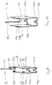
- FIG. 1 shows a view of a heater 1, which consists in principle of a heating section 2 and a plug part 4.
- the power supply lines for contacting the heater 1 are arranged in this plug part 4.
- the heating section 2 is inserted into a receptacle or pocket of a component to be heated, for example an SCR tank, the heating section 2 lying flat against the wall of this receptacle so that a good heat transfer is ensured.
- a non-electrically insulating insulating film 6 which optimizes the heat transfer is provided in the abutment region on the receptacle, not shown, on the heating section 2, which will be described in more detail later.
- a plug contour is attached, to which a correspondingly profiled plug connection of the power supply is applied, this plug contour 8 being designed so that a correct position mounting is ensured.
- FIG. 2 shows a plan view of the plug part 4 FIG. 1 , It can be seen a plug flange 10, in accordance with the view FIG. 2 covers the heating section 2 and also acts as insertion limit for this.
- the profiled plug part 4 engages with a peripheral wall a plug space 12, in which the above-mentioned plug of the power supply is at least partially immersed.
- a plug space 12 At the bottom of this plug chamber 12 can be seen two projecting into this tongue-shaped power supply lines 14, 16 of the heating section 2 and also in this plug space 12 hineing protruding actuating projection 18 of an activation pin 20.
- This actuating projection 18 is supported on two spring tongues 22, 24 of the plug part 4 and extends through the bottom of the plug space 12 into the heating section 2.
- the spring tongues 22, 24 each have a locking projection which dips into recesses 26, 78 of the activation pin 20. In the release position of the activation pins 20, the spring tongues 22, 24 engage in the recess 78 of the activation pin 20, this is thus fixed in position against accidental displacement. If one acts on the actuating projection 18 in the illustration according to FIG. 2 From the viewer forth with a thrust, so the resilient engagement of the spring tongues 22, 24 is released, so that the activation pin 20 can be moved in the direction of the heating section 2. In the operative position, the Spring tongues 22, 24 then into the recess 26 of the activation pin and lock it. This feature is explained in detail below.
- FIG. 3 shows the heater 1 according to FIG. 1 With removed insulating film 6.
- FIG. 4 shows the plug part 4 alone without heating section 2. Accordingly, extending from the plug flange 10 down on both sides of the heating section ( Fig. 3 ) arranged holding legs 28, 30, which form practically end walls of the heating section 2. These holding legs 28, 30 are in turn designed with a profile 32, which allows a positional fixation in the recording of the component to be heated.
- the plug part 4 of the heater 1 is preferably made by injection molding of plastic.
- the latching lugs 33, 35 take the force (activating force) resulting from the insertion of the activation pin 20 onto the heating insert FIGS. 5 and 6 on.
- FIG. 5 shows a representation of the heater 1 with removed connector part 4. It can be clearly seen the U-shaped insulating film 6, the open side areas by the above, in FIG. 5 not visible retaining legs 28, 30 are covered. In this illustration, one recognizes the two power supply lines 14, 16 and the activation pin 20 with its actuating projection 18. In this the above-described recess 26 is formed, in which the (non-visible) spring tongues 22, 24 resiliently engage, said resilient engagement relatively easily can be canceled.
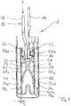
- the heating section 2 of the heater 1 is formed in this case with four PTC heating elements 34a, 34b and 36a, 36b, in the view according to FIG. 6 are clearly visible that the heater 1 shown without plug part 4 in a view rotated by about 90 ° FIG. 5 shows. Accordingly, in each case two PTC heating elements 34a, 34b and 36a, 36b face each other in pairs, the large areas of these PTC resistance elements extending parallel to the large areas of the insulating film 6. The space between the PTC resistance elements 34a, 34b and 36a, 36b is immersed approximately U-shaped trained first contact element 38 of the power supply 16 a, whose structure is particularly good FIG. 6 and the individual presentation according to FIG. 8 is removable.
- this first contact element 38 has two electrode plates 40, 42, each of which bears against one of the PTC resistor element pairs 34a, 34b or 36a, 36b and whose base area approximately corresponds to that of the associated resistor element pair.
- the two electrode plates 40, 42 are each connected to the front side by a base part 44a, 44b.
- Each of these base parts 44a, 44b is designed with an indentation 46a, 46b, so that the two electrode plates 40, 42 are elastically and parallel movable by elastic deformation of the base parts 44a, 44b and the associated indentations 46a, 46b.
- FIG. 5 are on the side edges of the electrode plates 40, 42 locking recesses 47, 49 for locking with the locking lugs 33, 35 are formed. In addition to the latching of the recesses 47, 49 and the activation force is added.
- the contact tongue 48 is connected to the electrode plate 40 via an approximately U-shaped bent contact leg 50.
- a spring element 52, 54 (see FIGS. 6 and 7 ) held.
- two Crimplaschen 56a, 56b and 58a, 58b (see FIG. 8 ), each of which laterally surround an upper transverse strut 60, 62 of the respective spring element 52, 54.
- the two spring elements 48, 50 further have according to the individual representation in FIG. 9 and the FIGS. 6 and 7 lower transverse struts 64, 66 which extend parallel to the upper transverse struts 60, 62 and between which two mutually spaced spring bridges 68a, 68b and 70a, 70b arch each other.
- FIGS. 6 and 7 lower transverse struts 64, 66 which extend parallel to the upper transverse struts 60, 62 and between which two mutually spaced spring bridges 68a, 68b and 70a, 70b arch each other.
- each spring bridge 68a, 70a lying in the direction of viewing are visible, and the associated spring bridges 68b and 70b are in the view according to FIG FIG. 7 covered by the spring bridges 68a and 70a and in the view according to FIG. 6 not visible.
- At the lateral narrow edges of the upper transverse struts 60, 62 are each two recesses 61 a, 61 b formed in the mounted state of the Crimplaschen 56a, 56b; 58a, 58b are encompassed in order to connect the spring elements 52, 54 with the corresponding power supply lines 14, 16 mechanically.
- Each spring element 52, 54 is thus supported with its upper and lower transverse struts 60, 64 and 62, 66 on the associated electrode plate 40, 42, wherein a lateral position fixing on the formed on each electrode plate 40, 42 Crimplaschen 56 a, 56 b and 58a, 58b takes place.
- the two vertices 72, 74 ( FIG. 7 ) of the spring bridges 68, 70 are at a comparatively small distance from one another.
- an activation section 76 of the activation pin 20 dips into the area between the opposing spring bridges 68, 70 and is in the mounting position or release position (see FIG. 7 ) but not in touching contact with the spring elements 52, 54.
- this has an approximately fork-shaped structure, wherein the actuating projection 18 with the recess 26 and a further opening 78 upwards (view FIG. 10 ) protrudes from a slightly raised to the level of the activation section 76 connection 80 from which two legs 82, 84 extend, which together form the activation section 76.
- These legs have a folded end portion 86, 88, which is bent back by a bending operation on the plane of the attachment-side part of the legs 82, 84, in which case the end-side end face regions 90, 92 are again slightly bent out of this plane.
- the activation pin 20 is displaceable via suitable guides in the plug part 4 (vertically in FIG. 6 ) guided.
- FIG. 11 shows a single representation of the second power supply 14, which has a similar structure as that based FIG. 8 explained power supply 16 has and according to the representations in the FIGS. 5 and 6 is nested with this.
- the power supply 14 has two electrode plates 94, 96 with approximately the same base area as the electrode plates 40, 42. Both electrode plates 94, 96 are in turn connected to one another via frontally connected base parts 98a, 98b, each with a concavity 100a, 100b.
- FIG. 11 shows a single representation of the second power supply 14, which has a similar structure as that based FIG. 8 explained power supply 16 has and according to the representations in the FIGS. 5 and 6 is nested with this.
- the power supply 14 has two electrode plates 94, 96 with approximately the same base area as the electrode plates 40, 42. Both electrode plates 94, 96 are in turn connected to one another via frontally connected base parts 98a, 98b, each with a concavity 100a, 100b.
- a contact tongue 102 is connected to the electrode plate 94 via a U-part 104.
- Both power supply lines 14, 16 are formed as stamped and bent parts.
- FIG. 11 is formed on the electrode plate 96, a fixing element 110, the more clearly in the figure FIG. 5 is visible. During assembly, this fixing element 110 engages in a corresponding recess of the plug part 4 in order to fix the heating section 2.
- FIG. 12 shows a heater 1 used in a receptacle or pocket of a container to be heated, wherein the heating section 2 is received flush in the pocket 106 and the plug member 4 is seated with the plug flange 10 on an outer surface 108.
- the insulating sheet 6 sits flat against the peripheral walls of the pocket 106, wherein, however, the end face of the heating section 2 may be spaced to a bottom of the bag.
- the activation pin 20 in its in FIG. 7 leave shown position in which the electrode plates 40, 42 and 94, 96 are not contacted with the PTC resistor elements 34, 36 with bias.
- the insulating film 6 is not pressed against the wall of the pocket 106.
- the gap s between the inner electrode plates 40, 42 and the respectively associated PTC resistor elements 34a, 34b; 36a, 36b available.
- the activation pin 20 via the projecting into the plug space 12 actuating projection 18 from the illustration FIG. 6 moved down ( Fig.
- the insulating film 6 serves as electrical insulation.
- the insulating film can also be used as a compensation for slight bumps in the recording of the component.
- a particular advantage of this design is that any existing manufacturing tolerances and temperature-related dimensional variations can be compensated by the considerable spring force of the spring bridges 74a, 74b, so that a sufficient mechanical, thermal and electrical contact is always ensured.
- the assembly of the heater 1 itself and its insertion into the receptacle is facilitated by the game s.
- this concept can be further simplified if the actuating projection 18 of the activation pin 20 acts as a power supply, so that then the energization is only possible when adjusting the activation pin 20 in its activation position.
- the construction principle underlying the invention can be easily adapted to different sizes and benefits.
- an electrical heater with at least one heating element, which can be brought into thermal contact with a wall of a component to be heated.
- This heating section is provided with an activation pin, which is adjustable from a release position to an activation position to adjust the heating element after insertion into the receptacle in an operative position in which a sufficient thermal and / or electrical contact is ensured.
Landscapes
- Resistance Heating (AREA)
Claims (14)
- Chauffage électrique, qui est employé avec une section de chauffe (2) dans un logement d'un composant devant être thermostaté, comprenant des éléments de chauffe (34, 36), alimentés en courant par l'intermédiaire d'arrivées de courant (14, 16) et qui peuvent être amenés directement ou indirectement en contact thermique avec une paroi du logement, caractérisé par une broche d'activation (20), qui peut être ajustée depuis une position de déverrouillage dans une position d'activation afin de régler les éléments de chauffe (34, 36) depuis une position de montage, dans laquelle ils ne se trouvent pas, ou ne se trouvent que dans une faible mesure, en contact thermique avec la paroi ou en contact électrique avec les arrivées de courant (14, 16) associées, dans une position opérationnelle, dans laquelle le contact thermique et/ou le contact électrique sont garantis,
le chauffage possédant tout au moins deux éléments de chauffe (34, 36) disposés à l'opposé l'un de l'autre, auxquels est respectivement associé un élément de ressort (52, 54), la broche d'activation (20) plongeant dans sa position d'activation entre les deux éléments de ressort (42, 44), afin d'appliquer aux éléments de chauffe une pré-tension du ressort, dans la direction de la paroi ou dans le sens d'un contact. - Chauffage selon la revendication de brevet 1, dans lequel la broche d'activation (20) a une saillie d'actionnement (18) en porte à faux et une section d'activation (76), situé du côté des éléments de chauffe et qui parvient en liaison d'actionnement avec l'un des éléments de chauffe (34, 36) en vue de l'activation.
- Chauffage selon la revendication de brevet 2, dans lequel les arrivées de courant (14, 16) se dressent dans une chambre de connecteur (12) d'un élément de connecteur (4), dans laquelle pénètre également la saillie d'actionnement (18) de la broche d'activation (20).
- Chauffage selon l'une des revendications précédentes de brevet, dans lequel à l'une des arrivées de courant (14, 16) est tout au moins associé un élément de ressort (52, 54) qui sollicite, dans la position opérationnelle de la broche d'activation (20), l'un des éléments de chauffe dans la direction de la paroi ou dans le sens d'un contact électrique.
- Chauffage selon la revendication de brevet 4, dans lequel l'élément de ressort (52, 54) est fixé à l'arrivée de courant (14, 16).
- Chauffage selon la revendication de brevet 5, dans lequel l'élément de ressort (52, 54) est maintenu par l'intermédiaire de languettes crimp (56, 58).
- Chauffage selon la revendication de brevet 4 ou 5, dans lequel les arrivées de courant (14, 16) est conçues de manière élastique.
- Chauffage selon la revendication de brevet 7, dans lequel chaque arrivée de courant (14, 16) a une structure en forme de U, dans lequel un renflement concave (46, 100) est respectivement conçu au niveau d'un élément de base (44, 98) en vue de la préparation de l'effet de ressort.
- Chauffage selon la revendication de brevet 7, dans lequel les deux arrivées de courant (14, 16) sont conçues de manière élastique.
- Chauffage selon l'une des revendications de brevet 1 à 9, dans lequel quatre éléments de chauffe (34a, 34b ; 36a, 36b) sont prévus, lesquels sont positionnés par paires de manière opposée l'une par rapport à l'autre et entre lesquels sont disposés les éléments de ressort (52, 54), auxquels une broche d'activation (20) est associée en commun.
- Chauffage selon l'une des revendications précédentes de brevet, dans lequel la broche d'activation (20) est conçue comme une pièce pliée et matricée avec deux sections d'extrémité (86, 88) repliées, formant la section d'activation (76).
- Chauffage selon l'une des revendications précédentes de brevet, dans lequel la broche d'activation (20) est fixée en position dans la position d'activation par engagement de force ou par coopération de forme.
- Chauffage selon l'une des revendications précédentes de brevet, dans lequel les éléments de chauffe sont des éléments à résistance PTC (34, 36).
- Chauffage selon l'une des revendications précédentes de brevet, dans lequel la section de chauffe (2) a un film isolant dans la zone d'application, au niveau de la paroi (6).
Priority Applications (1)
| Application Number | Priority Date | Filing Date | Title |
|---|---|---|---|
| EP16165765.5A EP3073800B1 (fr) | 2010-09-10 | 2011-09-12 | Chauffage electrique |
Applications Claiming Priority (1)
| Application Number | Priority Date | Filing Date | Title |
|---|---|---|---|
| DE102010037479.2A DE102010037479B4 (de) | 2010-09-10 | 2010-09-10 | Elektrischer Heizer |
Related Child Applications (1)
| Application Number | Title | Priority Date | Filing Date |
|---|---|---|---|
| EP16165765.5A Division EP3073800B1 (fr) | 2010-09-10 | 2011-09-12 | Chauffage electrique |
Publications (2)
| Publication Number | Publication Date |
|---|---|
| EP2429257A1 EP2429257A1 (fr) | 2012-03-14 |
| EP2429257B1 true EP2429257B1 (fr) | 2016-04-20 |
Family
ID=44677701
Family Applications (2)
| Application Number | Title | Priority Date | Filing Date |
|---|---|---|---|
| EP16165765.5A Active EP3073800B1 (fr) | 2010-09-10 | 2011-09-12 | Chauffage electrique |
| EP11180922.4A Active EP2429257B1 (fr) | 2010-09-10 | 2011-09-12 | Chauffage électrique |
Family Applications Before (1)
| Application Number | Title | Priority Date | Filing Date |
|---|---|---|---|
| EP16165765.5A Active EP3073800B1 (fr) | 2010-09-10 | 2011-09-12 | Chauffage electrique |
Country Status (4)
| Country | Link |
|---|---|
| EP (2) | EP3073800B1 (fr) |
| DE (1) | DE102010037479B4 (fr) |
| DK (1) | DK2429257T3 (fr) |
| ES (1) | ES2575134T3 (fr) |
Families Citing this family (4)
| Publication number | Priority date | Publication date | Assignee | Title |
|---|---|---|---|---|
| US10093538B2 (en) | 2012-11-19 | 2018-10-09 | Intelligent Energy Inc. | Heater assembly, hydrogen generator and method of providing hydrogen gas |
| US9243560B2 (en) * | 2012-11-19 | 2016-01-26 | Intelligent Energy Inc. | Hydrogen generator having a thermal actuator |
| DE102017123549A1 (de) * | 2017-10-10 | 2019-04-11 | Eichenauer Heizelemente Gmbh & Co. Kg | Tankheizung |
| CN110145808B (zh) * | 2019-06-24 | 2024-06-07 | 宁波奥克斯电气股份有限公司 | 一种可折叠空调辅助电加热装置及空调 |
Family Cites Families (10)
| Publication number | Priority date | Publication date | Assignee | Title |
|---|---|---|---|---|
| US3940591A (en) * | 1974-07-01 | 1976-02-24 | Texas Instruments Incorporated | Self-regulating electric heater |
| US4395623A (en) * | 1980-03-04 | 1983-07-26 | Murata Manufacturing Co., Ltd. | Self-regulating electric heater |
| US5194717A (en) * | 1990-10-18 | 1993-03-16 | Tecumseh Products Company | Bracket for mounting a crankcase heater |
| DE59200295D1 (de) | 1991-08-12 | 1994-08-25 | Siemens Matsushita Components | Heizvorrichtung zum Erwärmen strömender Medien. |
| US6455822B1 (en) * | 2000-10-11 | 2002-09-24 | Mega Dynamics Ltd. | Heat sink for a PTC heating element and a PTC heating member made thereof |
| ES2236398T3 (es) | 2002-06-27 | 2005-07-16 | DAVID & BAADER DBK SPEZIALFABRIK ELEKTRISCHER APPARATE UND HEIZWIDERSTANDE GMBH | Dispositivo de calentamiento para un conducto y procedimiento de construccion. |
| DE10325965B4 (de) | 2003-06-07 | 2007-01-11 | Mann + Hummel Gmbh | Heizeinrichtung für Fluide |
| US7537000B2 (en) | 2006-02-14 | 2009-05-26 | Honda Motor Co., Ltd | Engine with breather apparatus |
| JP2008071553A (ja) * | 2006-09-13 | 2008-03-27 | Calsonic Kansei Corp | 電気ヒータ装置およびその製造方法 |
| US8232509B2 (en) * | 2006-11-16 | 2012-07-31 | S.C. Johnson & Son, Inc. | Retainer system |
-
2010
- 2010-09-10 DE DE102010037479.2A patent/DE102010037479B4/de not_active Expired - Fee Related
-
2011
- 2011-09-12 DK DK11180922.4T patent/DK2429257T3/en active
- 2011-09-12 EP EP16165765.5A patent/EP3073800B1/fr active Active
- 2011-09-12 ES ES11180922.4T patent/ES2575134T3/es active Active
- 2011-09-12 EP EP11180922.4A patent/EP2429257B1/fr active Active
Also Published As
| Publication number | Publication date |
|---|---|
| EP3073800B1 (fr) | 2020-01-15 |
| DE102010037479B4 (de) | 2023-03-16 |
| EP3073800A1 (fr) | 2016-09-28 |
| ES2575134T3 (es) | 2016-06-24 |
| EP2429257A1 (fr) | 2012-03-14 |
| DK2429257T3 (en) | 2016-08-01 |
| DE102010037479A1 (de) | 2012-03-15 |
Similar Documents
| Publication | Publication Date | Title |
|---|---|---|
| EP2866306B1 (fr) | Prise de contact pour un connecteur à fiches électrique | |
| EP1720219A1 (fr) | Element électrique de connexion | |
| DE202014011610U1 (de) | Halterahmen für einen Steckverbinder | |
| EP2429257B1 (fr) | Chauffage électrique | |
| EP2298582A1 (fr) | Dispositif de chauffage électrique et son procédé de fabrication | |
| DE102007053722A1 (de) | Hermaphroditischer Steckverbinder | |
| DE102014117062B4 (de) | Federkraftklemme | |
| DE102005033696B4 (de) | Kontaktelement | |
| WO2018073346A1 (fr) | Élément de contact | |
| DE102009036807B4 (de) | Elektrische Steckverbinderanordnung mit verringerter Steckkraft | |
| EP2126327B1 (fr) | Dispositif de génération de gradients de température | |
| EP3598847B1 (fr) | Élément produisant de la chaleur et son procédé de fabrication | |
| EP0860846B1 (fr) | Régulateur électrique de puissance, en particulier pour appareil à chauffage électrique | |
| DE102017124670A1 (de) | Elektrische Steckverbindung | |
| DE102013101736A1 (de) | Anordnung zur Befestigung und Positionierung von Relais | |
| BE1026101B1 (de) | Kontaktelement mit einem Kontaktkörper und einem daran angeordneten Federelement | |
| DE19946627B4 (de) | Elektrische Steckverbindung | |
| EP0388598A1 (fr) | Boîtier de connexions électriques d'une pièce | |
| DE102006049765B4 (de) | Flachsteckbuchse für ein Kraftfahrzeug | |
| EP2498577B1 (fr) | Agencement pour un champ de cuisson ainsi que champ de cuisson à induction doté d'un agencement correspondant | |
| EP0447859A2 (fr) | Plaque de cuisson électrique | |
| DE102018127202A1 (de) | PTC-Heizung | |
| DE19706249B4 (de) | Elektrisches Steuergerät, insbesondere für Elektrowärmegeräte und Verfahren zu seiner Herstellung | |
| WO2024037909A1 (fr) | Borne de connexion pour le raccordement d'une ligne électrique | |
| DE102024114161A1 (de) | Flachkontaktbuchse |
Legal Events
| Date | Code | Title | Description |
|---|---|---|---|
| AK | Designated contracting states |
Kind code of ref document: A1 Designated state(s): AL AT BE BG CH CY CZ DE DK EE ES FI FR GB GR HR HU IE IS IT LI LT LU LV MC MK MT NL NO PL PT RO RS SE SI SK SM TR |
|
| AX | Request for extension of the european patent |
Extension state: BA ME |
|
| PUAI | Public reference made under article 153(3) epc to a published international application that has entered the european phase |
Free format text: ORIGINAL CODE: 0009012 |
|
| RIN1 | Information on inventor provided before grant (corrected) |
Inventor name: LECOENT, PATRICK Inventor name: HEIDELBERGER, WALTER |
|
| 17P | Request for examination filed |
Effective date: 20120827 |
|
| RAP1 | Party data changed (applicant data changed or rights of an application transferred) |
Owner name: DBK DAVID + BAADER GMBH |
|
| 17Q | First examination report despatched |
Effective date: 20150223 |
|
| GRAP | Despatch of communication of intention to grant a patent |
Free format text: ORIGINAL CODE: EPIDOSNIGR1 |
|
| INTG | Intention to grant announced |
Effective date: 20151021 |
|
| GRAS | Grant fee paid |
Free format text: ORIGINAL CODE: EPIDOSNIGR3 |
|
| GRAA | (expected) grant |
Free format text: ORIGINAL CODE: 0009210 |
|
| AK | Designated contracting states |
Kind code of ref document: B1 Designated state(s): AL AT BE BG CH CY CZ DE DK EE ES FI FR GB GR HR HU IE IS IT LI LT LU LV MC MK MT NL NO PL PT RO RS SE SI SK SM TR |
|
| REG | Reference to a national code |
Ref country code: GB Ref legal event code: FG4D Free format text: NOT ENGLISH |
|
| REG | Reference to a national code |
Ref country code: CH Ref legal event code: EP |
|
| REG | Reference to a national code |
Ref country code: AT Ref legal event code: REF Ref document number: 793649 Country of ref document: AT Kind code of ref document: T Effective date: 20160515 |
|
| REG | Reference to a national code |
Ref country code: IE Ref legal event code: FG4D Free format text: LANGUAGE OF EP DOCUMENT: GERMAN |
|
| REG | Reference to a national code |
Ref country code: DE Ref legal event code: R096 Ref document number: 502011009502 Country of ref document: DE |
|
| REG | Reference to a national code |
Ref country code: SE Ref legal event code: TRGR |
|
| REG | Reference to a national code |
Ref country code: ES Ref legal event code: FG2A Ref document number: 2575134 Country of ref document: ES Kind code of ref document: T3 Effective date: 20160624 |
|
| REG | Reference to a national code |
Ref country code: DK Ref legal event code: T3 Effective date: 20160725 |
|
| REG | Reference to a national code |
Ref country code: NO Ref legal event code: T2 Effective date: 20160420 |
|
| REG | Reference to a national code |
Ref country code: LT Ref legal event code: MG4D |
|
| REG | Reference to a national code |
Ref country code: FR Ref legal event code: PLFP Year of fee payment: 6 |
|
| REG | Reference to a national code |
Ref country code: NL Ref legal event code: MP Effective date: 20160420 |
|
| PG25 | Lapsed in a contracting state [announced via postgrant information from national office to epo] |
Ref country code: PL Free format text: LAPSE BECAUSE OF FAILURE TO SUBMIT A TRANSLATION OF THE DESCRIPTION OR TO PAY THE FEE WITHIN THE PRESCRIBED TIME-LIMIT Effective date: 20160420 Ref country code: NL Free format text: LAPSE BECAUSE OF FAILURE TO SUBMIT A TRANSLATION OF THE DESCRIPTION OR TO PAY THE FEE WITHIN THE PRESCRIBED TIME-LIMIT Effective date: 20160420 Ref country code: LT Free format text: LAPSE BECAUSE OF FAILURE TO SUBMIT A TRANSLATION OF THE DESCRIPTION OR TO PAY THE FEE WITHIN THE PRESCRIBED TIME-LIMIT Effective date: 20160420 |
|
| PG25 | Lapsed in a contracting state [announced via postgrant information from national office to epo] |
Ref country code: PT Free format text: LAPSE BECAUSE OF FAILURE TO SUBMIT A TRANSLATION OF THE DESCRIPTION OR TO PAY THE FEE WITHIN THE PRESCRIBED TIME-LIMIT Effective date: 20160822 Ref country code: RS Free format text: LAPSE BECAUSE OF FAILURE TO SUBMIT A TRANSLATION OF THE DESCRIPTION OR TO PAY THE FEE WITHIN THE PRESCRIBED TIME-LIMIT Effective date: 20160420 Ref country code: HR Free format text: LAPSE BECAUSE OF FAILURE TO SUBMIT A TRANSLATION OF THE DESCRIPTION OR TO PAY THE FEE WITHIN THE PRESCRIBED TIME-LIMIT Effective date: 20160420 Ref country code: LV Free format text: LAPSE BECAUSE OF FAILURE TO SUBMIT A TRANSLATION OF THE DESCRIPTION OR TO PAY THE FEE WITHIN THE PRESCRIBED TIME-LIMIT Effective date: 20160420 Ref country code: GR Free format text: LAPSE BECAUSE OF FAILURE TO SUBMIT A TRANSLATION OF THE DESCRIPTION OR TO PAY THE FEE WITHIN THE PRESCRIBED TIME-LIMIT Effective date: 20160721 |
|
| REG | Reference to a national code |
Ref country code: DE Ref legal event code: R097 Ref document number: 502011009502 Country of ref document: DE |
|
| PG25 | Lapsed in a contracting state [announced via postgrant information from national office to epo] |
Ref country code: CZ Free format text: LAPSE BECAUSE OF FAILURE TO SUBMIT A TRANSLATION OF THE DESCRIPTION OR TO PAY THE FEE WITHIN THE PRESCRIBED TIME-LIMIT Effective date: 20160420 Ref country code: RO Free format text: LAPSE BECAUSE OF FAILURE TO SUBMIT A TRANSLATION OF THE DESCRIPTION OR TO PAY THE FEE WITHIN THE PRESCRIBED TIME-LIMIT Effective date: 20160420 Ref country code: SK Free format text: LAPSE BECAUSE OF FAILURE TO SUBMIT A TRANSLATION OF THE DESCRIPTION OR TO PAY THE FEE WITHIN THE PRESCRIBED TIME-LIMIT Effective date: 20160420 Ref country code: EE Free format text: LAPSE BECAUSE OF FAILURE TO SUBMIT A TRANSLATION OF THE DESCRIPTION OR TO PAY THE FEE WITHIN THE PRESCRIBED TIME-LIMIT Effective date: 20160420 |
|
| PLBE | No opposition filed within time limit |
Free format text: ORIGINAL CODE: 0009261 |
|
| STAA | Information on the status of an ep patent application or granted ep patent |
Free format text: STATUS: NO OPPOSITION FILED WITHIN TIME LIMIT |
|
| PG25 | Lapsed in a contracting state [announced via postgrant information from national office to epo] |
Ref country code: BE Free format text: LAPSE BECAUSE OF NON-PAYMENT OF DUE FEES Effective date: 20160930 Ref country code: SM Free format text: LAPSE BECAUSE OF FAILURE TO SUBMIT A TRANSLATION OF THE DESCRIPTION OR TO PAY THE FEE WITHIN THE PRESCRIBED TIME-LIMIT Effective date: 20160420 |
|
| 26N | No opposition filed |
Effective date: 20170123 |
|
| PG25 | Lapsed in a contracting state [announced via postgrant information from national office to epo] |
Ref country code: MC Free format text: LAPSE BECAUSE OF FAILURE TO SUBMIT A TRANSLATION OF THE DESCRIPTION OR TO PAY THE FEE WITHIN THE PRESCRIBED TIME-LIMIT Effective date: 20160420 |
|
| REG | Reference to a national code |
Ref country code: CH Ref legal event code: PL |
|
| PG25 | Lapsed in a contracting state [announced via postgrant information from national office to epo] |
Ref country code: SI Free format text: LAPSE BECAUSE OF FAILURE TO SUBMIT A TRANSLATION OF THE DESCRIPTION OR TO PAY THE FEE WITHIN THE PRESCRIBED TIME-LIMIT Effective date: 20160420 |
|
| REG | Reference to a national code |
Ref country code: IE Ref legal event code: MM4A |
|
| PG25 | Lapsed in a contracting state [announced via postgrant information from national office to epo] |
Ref country code: CH Free format text: LAPSE BECAUSE OF NON-PAYMENT OF DUE FEES Effective date: 20160930 Ref country code: IE Free format text: LAPSE BECAUSE OF NON-PAYMENT OF DUE FEES Effective date: 20160912 Ref country code: LI Free format text: LAPSE BECAUSE OF NON-PAYMENT OF DUE FEES Effective date: 20160930 |
|
| PG25 | Lapsed in a contracting state [announced via postgrant information from national office to epo] |
Ref country code: LU Free format text: LAPSE BECAUSE OF NON-PAYMENT OF DUE FEES Effective date: 20160912 |
|
| REG | Reference to a national code |
Ref country code: FR Ref legal event code: PLFP Year of fee payment: 7 |
|
| PGFP | Annual fee paid to national office [announced via postgrant information from national office to epo] |
Ref country code: NO Payment date: 20170921 Year of fee payment: 7 Ref country code: FI Payment date: 20170920 Year of fee payment: 7 Ref country code: IT Payment date: 20170926 Year of fee payment: 7 |
|
| REG | Reference to a national code |
Ref country code: AT Ref legal event code: MM01 Ref document number: 793649 Country of ref document: AT Kind code of ref document: T Effective date: 20160912 |
|
| REG | Reference to a national code |
Ref country code: BE Ref legal event code: MM Effective date: 20160930 |
|
| PGFP | Annual fee paid to national office [announced via postgrant information from national office to epo] |
Ref country code: DK Payment date: 20170925 Year of fee payment: 7 |
|
| PG25 | Lapsed in a contracting state [announced via postgrant information from national office to epo] |
Ref country code: AT Free format text: LAPSE BECAUSE OF NON-PAYMENT OF DUE FEES Effective date: 20160912 |
|
| PG25 | Lapsed in a contracting state [announced via postgrant information from national office to epo] |
Ref country code: HU Free format text: LAPSE BECAUSE OF FAILURE TO SUBMIT A TRANSLATION OF THE DESCRIPTION OR TO PAY THE FEE WITHIN THE PRESCRIBED TIME-LIMIT; INVALID AB INITIO Effective date: 20110912 Ref country code: CY Free format text: LAPSE BECAUSE OF FAILURE TO SUBMIT A TRANSLATION OF THE DESCRIPTION OR TO PAY THE FEE WITHIN THE PRESCRIBED TIME-LIMIT Effective date: 20160420 |
|
| PG25 | Lapsed in a contracting state [announced via postgrant information from national office to epo] |
Ref country code: IS Free format text: LAPSE BECAUSE OF FAILURE TO SUBMIT A TRANSLATION OF THE DESCRIPTION OR TO PAY THE FEE WITHIN THE PRESCRIBED TIME-LIMIT Effective date: 20160420 Ref country code: TR Free format text: LAPSE BECAUSE OF FAILURE TO SUBMIT A TRANSLATION OF THE DESCRIPTION OR TO PAY THE FEE WITHIN THE PRESCRIBED TIME-LIMIT Effective date: 20160420 Ref country code: MK Free format text: LAPSE BECAUSE OF FAILURE TO SUBMIT A TRANSLATION OF THE DESCRIPTION OR TO PAY THE FEE WITHIN THE PRESCRIBED TIME-LIMIT Effective date: 20160420 Ref country code: MT Free format text: LAPSE BECAUSE OF FAILURE TO SUBMIT A TRANSLATION OF THE DESCRIPTION OR TO PAY THE FEE WITHIN THE PRESCRIBED TIME-LIMIT Effective date: 20160420 |
|
| PG25 | Lapsed in a contracting state [announced via postgrant information from national office to epo] |
Ref country code: BG Free format text: LAPSE BECAUSE OF FAILURE TO SUBMIT A TRANSLATION OF THE DESCRIPTION OR TO PAY THE FEE WITHIN THE PRESCRIBED TIME-LIMIT Effective date: 20160420 |
|
| REG | Reference to a national code |
Ref country code: FR Ref legal event code: PLFP Year of fee payment: 8 |
|
| PG25 | Lapsed in a contracting state [announced via postgrant information from national office to epo] |
Ref country code: AL Free format text: LAPSE BECAUSE OF FAILURE TO SUBMIT A TRANSLATION OF THE DESCRIPTION OR TO PAY THE FEE WITHIN THE PRESCRIBED TIME-LIMIT Effective date: 20160420 |
|
| REG | Reference to a national code |
Ref country code: NO Ref legal event code: MMEP |
|
| PG25 | Lapsed in a contracting state [announced via postgrant information from national office to epo] |
Ref country code: FI Free format text: LAPSE BECAUSE OF NON-PAYMENT OF DUE FEES Effective date: 20180912 |
|
| REG | Reference to a national code |
Ref country code: DK Ref legal event code: EBP Effective date: 20180930 |
|
| PG25 | Lapsed in a contracting state [announced via postgrant information from national office to epo] |
Ref country code: NO Free format text: LAPSE BECAUSE OF NON-PAYMENT OF DUE FEES Effective date: 20180930 Ref country code: IT Free format text: LAPSE BECAUSE OF NON-PAYMENT OF DUE FEES Effective date: 20180912 |
|
| PG25 | Lapsed in a contracting state [announced via postgrant information from national office to epo] |
Ref country code: DK Free format text: LAPSE BECAUSE OF NON-PAYMENT OF DUE FEES Effective date: 20180930 |
|
| PGFP | Annual fee paid to national office [announced via postgrant information from national office to epo] |
Ref country code: SE Payment date: 20210921 Year of fee payment: 11 |
|
| PGFP | Annual fee paid to national office [announced via postgrant information from national office to epo] |
Ref country code: ES Payment date: 20211019 Year of fee payment: 11 |
|
| PGFP | Annual fee paid to national office [announced via postgrant information from national office to epo] |
Ref country code: GB Payment date: 20220927 Year of fee payment: 12 |
|
| REG | Reference to a national code |
Ref country code: SE Ref legal event code: EUG |
|
| P01 | Opt-out of the competence of the unified patent court (upc) registered |
Effective date: 20230525 |
|
| PG25 | Lapsed in a contracting state [announced via postgrant information from national office to epo] |
Ref country code: SE Free format text: LAPSE BECAUSE OF NON-PAYMENT OF DUE FEES Effective date: 20220913 |
|
| REG | Reference to a national code |
Ref country code: ES Ref legal event code: FD2A Effective date: 20231027 |
|
| PG25 | Lapsed in a contracting state [announced via postgrant information from national office to epo] |
Ref country code: ES Free format text: LAPSE BECAUSE OF NON-PAYMENT OF DUE FEES Effective date: 20220913 |
|
| PG25 | Lapsed in a contracting state [announced via postgrant information from national office to epo] |
Ref country code: ES Free format text: LAPSE BECAUSE OF NON-PAYMENT OF DUE FEES Effective date: 20220913 |
|
| GBPC | Gb: european patent ceased through non-payment of renewal fee |
Effective date: 20230912 |
|
| PG25 | Lapsed in a contracting state [announced via postgrant information from national office to epo] |
Ref country code: GB Free format text: LAPSE BECAUSE OF NON-PAYMENT OF DUE FEES Effective date: 20230912 |
|
| PG25 | Lapsed in a contracting state [announced via postgrant information from national office to epo] |
Ref country code: GB Free format text: LAPSE BECAUSE OF NON-PAYMENT OF DUE FEES Effective date: 20230912 |
|
| PGFP | Annual fee paid to national office [announced via postgrant information from national office to epo] |
Ref country code: DE Payment date: 20250820 Year of fee payment: 15 |
|
| PGFP | Annual fee paid to national office [announced via postgrant information from national office to epo] |
Ref country code: FR Payment date: 20250925 Year of fee payment: 15 |