EP2429337B1 - Medizinschrank - Google Patents
Medizinschrank Download PDFInfo
- Publication number
- EP2429337B1 EP2429337B1 EP10716187.9A EP10716187A EP2429337B1 EP 2429337 B1 EP2429337 B1 EP 2429337B1 EP 10716187 A EP10716187 A EP 10716187A EP 2429337 B1 EP2429337 B1 EP 2429337B1
- Authority
- EP
- European Patent Office
- Prior art keywords
- storage cabinet
- wire management
- raceway
- cabinet
- storage
- Prior art date
- Legal status (The legal status is an assumption and is not a legal conclusion. Google has not performed a legal analysis and makes no representation as to the accuracy of the status listed.)
- Not-in-force
Links
Images



Classifications
-
- A—HUMAN NECESSITIES
- A47—FURNITURE; DOMESTIC ARTICLES OR APPLIANCES; COFFEE MILLS; SPICE MILLS; SUCTION CLEANERS IN GENERAL
- A47B—TABLES; DESKS; OFFICE FURNITURE; CABINETS; DRAWERS; GENERAL DETAILS OF FURNITURE
- A47B67/00—Chests; Dressing-tables; Medicine cabinets or the like; Cabinets characterised by the arrangement of drawers
- A47B67/02—Cabinets for shaving tackle, medicines, or the like
Definitions
- the present invention relates to storage cabinets such as medicine cabinets. See DE-A-3510670 which discloses a storage cabinet according to the preamble of claim 1.
- Some of these cabinets are provided with electrical power (e.g. to light the cabinet itself and/or to provide a plug-in site for personal care devices such as hair dryers, curling irons, toothbrushes and shavers). Se e generally U.S. patent 3,555,627 .
- the electrical wiring is linkable to an external power source (e.g. a building power supply), and another end of the electrical wiring is linked to an electric outlet (e.g. most preferably positioned on an outer face of the wire management raceway).
- an external power source e.g. a building power supply
- an electric outlet e.g. most preferably positioned on an outer face of the wire management raceway
- the pocket is suitable to conceal a portion of a power cord of an item (e.g. a curling iron) stored in the internal storage cavity when the item is not linked to a power supply.
- the outer housing can have a rear wall and the pocket can be located adjacent a junction between the rear wall and the wire management raceway.
- the pocket is associated with a flexible retainer suitable to assist in retaining such a power cord in the pocket if positioned therein, where the retainer is in a form of a flexible brush, gasket or bulb style seal.
- the wire management raceway can also have an array of means (e.g. holes or pegs) for supporting a shelf at selected heights in the internal storage cavity, and a shelf is at least partially supported thereon in the internal storage cavity.
- means e.g. holes or pegs
- the door is openable by a vertical sliding movement, and its movement is in part governed by a counterweight.
- the outlet can be positioned low enough along the raceway such that moving the door up slightly exposes the outlet, permitting a shaver or other electrical item to be powered from the outlet while a mirror on the front of the door is still useful.
- a recharging base for a rechargeable toothbrush for a rechargeable toothbrush
- Such an item might be "permanently” plugged into an upper outlet of the cabinet, leaving one or more lower outlets free for use by items such as a hairdryer.
- the recharging base could use a very high outlet 52 near the top of the raceway.
- a television associated with the medicine cabinet e.g. visible through the mirror on the front door
- a television associated with the medicine cabinet could be permanently plugged into an outlet along the raceway, such as an upper outlet.
- the raceway would then provide a permanent benefit with respect to cord management.
- raceway permits power to be supplied at optimal positions from a vertical standpoint.
- raceway allows removable shelves to be positioned as needed.
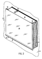
- a preferred assembly, generally 10, is shown in the drawings.
- a medicine cabinet 14 having a top wall 18, a bottom wall 20, opposed side walls 22, and preferably a rear wall 24, which together define an internal cavity. Dividing the cavity is a wire management raceway generally 12.
- a front door 28 (preferably mirrored and vertically slidable).
- the door 28 can have a horizontally extending handle 32 fixed along a lower edge 34 thereof to facilitate lifting and lowering of the door 28.
- the door 28 is slideably retained within a set of vertical tracks 38 formed along the side walls 22 of the enclosure 16.
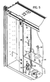
- the door 28 is connected to the counterweight 36 via a pair of toothed belts 40 extending over a roller 41 and respective gear wheels 42.
- the belts 40 engage and cooperate with the wheels 42 when lifting or lowering the door 28.
- Door 28 may be maintained in a partially opened position such as shown in FIG. 1 .
- the cabinet is suitable to be mounted onto a vertical wall 30 using brackets or other conventional means. Also, while the principles of the present invention are mostly intended for use in a medicine cabinet, it should be appreciated that they will also be valuable in the context of other cabinets such as kitchen cupboards, and personal workstations.
- Pegs can be positioned in various holes along the side walls 22 and raceway 12. Shelving 44 can be positioned thereon at desired vertical heights.
- Health and beauty aids such as cosmetics, toiletries, and the like may be conveniently stored on the shelves 44. Further, electric grooming devices 46 may be stored in a cabinet when not in use.
- a recharging base 48 positioned on a shelf 44 in FIG. 5 with its power cord managed by being partially concealed in a pocket defined by raceway 12, with the opposite end of its power cord linked into an outlet 52.
- a toothbrush 50 can be recharged without the consumer needing to keep the recharging device on a counter top or the like.
- the toothbrush recharging base can be permanently plugged in at an outlet 52 near the top of the raceway, to leave the lower outlets free for other purposes.
- outlets 52 can be at varied vertical heights, albeit placing them close to the bottom of the raceway 12 makes it easier to use a power outlet as well as a mirror on the front door 28 simultaneously.
- the raceway 12 can be a largely unitary structure. It can have spaced apart side walls 58 and a planar front wall 60 defining a generally U-shaped passage 62 therein.
- the outer housing of the cabinet together therewith create a passage 62 for electrical wiring, such that electrical wiring 64 and related electrical connections are isolated from the opposed lateral storage areas 26, helping to achieve compliance with various electrical wiring safety codes.
- each outlet 52 is formed with a substantially square housing 66 having a front end 68, a rear end 70, and a radial flange 72 adjacent to the front end 68.
- the outlet 52 is inserted through aligned square-shaped openings 82, 74 formed in the side wall 58 and a retaining plate 76 therein.
- the retaining plate 76 is secured within a pair of spaced apart slotted protrusions 80 formed inside the passage 62.
- a plurality of retaining clips 78 in the housing 66 are temporarily inwardly displaced when the outlet 52 is pushed further through the opening 74 in the retaining plate 76.
- the outlet 52 is fully inserted when the flange 72 abuts the retaining plate 76, allowing the clips 78 to return to their unbiased position. In such a position, the clips 78 firmly press against the retaining plate 76 to hold the outlet 52 in place.
- the front end 68 of the outlet 52 extends slightly through the opening 82 in the side wall 58 and presents an aesthetically pleasing appearance.
- one or more openings 84 may be provided in the top or bottom walls 18, 20 to permit entry of wiring from a building power supply (not shown) into the raceway 12.
- terminals 86 provided at the rear end 70 of the outlet 52.
- the cabinet may be wired to a GFI circuit breaker, if desired.
- Low profile push buttons or switches 88 may be provided on the front wall 60 of the raceway 12 to control a light 90 and/or one or more of the outlets 52.
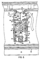
- each side wall 58 of the raceway 12 is provided near its rear with a pocket 94 in the form of an elongated channel 96 that is open externally.
- a flexible retainer 98 see FIG. 6 .
- the channel 96 may be integrally formed in the side walls 58 such as with a one-piece extrusion process, or, as illustrated, be formed by two extruded pieces 100, 102 fastened together with screws 104. Regardless of the manufacture process, the cross-sectional area of the channel 96 is large enough to accommodate one or more power cords 92.
- the retainer 98 may be made of a resilient material such as foam, rubber, or a brush strip capable of at least partially concealing the channel 96 and retaining power cords 92 placed therein.
- the retainer 98 is secured to the side wall 58 via frictional engagement with a slot 106 formed on one edge 108 of the channel 96.
- a suitable adhesive or heat welding may be used.
- the retainer 98 is inwardly angled and tapered and extends towards the other edge 110 of the channel 96.
- Parts of one or more power cords 92 may be pushed/tucked into the pocket 94 with a pressing force sufficient to temporarily displace the retainer 98. This may be when an item is not in use, or in the case of something like a recharging station when the full length of a power cord isn't needed.
- an associated plug 112 may be plugged into an outlet with unneeded cord length 92 retained within the pocket 94.
- the present invention provides storage cabinets such as medicine cabinets with improved structures for accommodating electrical wiring for the cabinets, and power cords for appliances used therewith.
Landscapes
- Catching Or Destruction (AREA)
- Drawers Of Furniture (AREA)
Claims (12)
- Ein Schrank (10) mit einem Gehäuse (14) mit sich gegenüberliegenden Seitenwänden (22), einer zu öffnenden vorderen Tür (28) und einem internem Stauraum zwischen den sich gegenüberliegenden Seitenwänden (22),
gekennzeichnet durch
eine vertikal verlaufende Kabelführung (12), die zwischen den sich gegenüberliegenden Seitenwänden (22) positioniert ist und so an den gegenüberliegenden Seiten der Kabelführung (12) Speicherräume im Stauraum definiert, wobei die Kabelführung (12) einen internen Durchgang (62) hat, in dem elektrische Kabel (64) untergebracht sind. - Der Schrank (10) entsprechend Anspruch 1, wobei der Schrank ein Medizinschrank ist.
- Der Schrank (10) entsprechend einem der vorhergehenden Ansprüche, wobei ein Ende des elektrischen Kabels (64) an eine externe Stromquelle angeschlossen ist und ein anderes Ende des elektrischen Kabels (64) an eine Steckdose (52) angeschlossen ist.
- Der Schrank (10) entsprechend Anspruch 3, wobei die Steckdose (52) an einer Außenfläche der Kabelführung (12) positioniert ist.
- Der Schrank (10) entsprechend einem der vorhergehenden Ansprüche, zu dem weiterhin ein Fach (94) in der Kabeldurchführung (12) gehört, das von außerhalb der Kabeldurchführung (12) zugänglich ist, wobei das Fach (94) sich dazu eignet, einen Teil eines Stromkabels eines Gegenstands, der im internen Stauraum untergebracht ist, aufzunehmen, wenn der Gegenstand nicht an die Stromzufuhr angeschlossen ist.
- Der Schrank (10) entsprechend Anspruch 5, wobei das Gehäuse (14) außerdem eine Rückwand (24) hat und das Fach (94) sich neben einer Verbindungsstelle zwischen der Rückwand (24) und der Kabelführung (12) befindet.
- Der Schrank (10) entsprechend Anspruch 5, wobei das Fach (94) mit einer flexiblen Halterung (98) verbunden ist, die dazu eignet, ein solches Stromkabel im Fach (94) zu halten, wenn es dort hineingeben wird.
- Der Schrank (10) entsprechend Anspruch 7, wobei die Halterung (98) aus der Gruppe bestehend aus flexiblen Buchsen, flexiblen Dichtungen und flexiblen Dichtungsstreifen ausgewählt wird.
- Der Schrank (10) entsprechend einem der vorhergehenden Ansprüche, wobei an der Kabeldurchführung (12) an ausgewählten Höhen im inneren Stauraum eine Reihe von Möglichkeiten zur Unterstützung eines Regals (44) vorhanden sind und ein Regal (44) hierauf im inneren Stauraum zumindest teilweise unterstützt wird.
- Der Schrank (10) entsprechend einem der vorhergehenden Ansprüche, wobei sich die Tür (28) durch eine Vertikale Schubbewegung öffnen lässt.
- Der Schrank (10) entsprechend Anspruch 10, wobei die Bewegung der Tür (28) teilweise durch ein Gegengewicht (36) geregelt wird.
- Der Schrank (10) entsprechend einem der vorhergehenden Ansprüche, wobei die Kabelführung (64) von den Speicherräumen isoliert ist.
Applications Claiming Priority (2)
| Application Number | Priority Date | Filing Date | Title |
|---|---|---|---|
| US12/428,827 US9675172B2 (en) | 2009-04-23 | 2009-04-23 | Medicine cabinet |
| PCT/US2010/031853 WO2010123968A1 (en) | 2009-04-23 | 2010-04-21 | Medicine cabinet |
Publications (2)
| Publication Number | Publication Date |
|---|---|
| EP2429337A1 EP2429337A1 (de) | 2012-03-21 |
| EP2429337B1 true EP2429337B1 (de) | 2014-07-23 |
Family
ID=42236622
Family Applications (1)
| Application Number | Title | Priority Date | Filing Date |
|---|---|---|---|
| EP10716187.9A Not-in-force EP2429337B1 (de) | 2009-04-23 | 2010-04-21 | Medizinschrank |
Country Status (4)
| Country | Link |
|---|---|
| US (1) | US9675172B2 (de) |
| EP (1) | EP2429337B1 (de) |
| CN (2) | CN105146932B (de) |
| WO (1) | WO2010123968A1 (de) |
Families Citing this family (27)
| Publication number | Priority date | Publication date | Assignee | Title |
|---|---|---|---|---|
| CN102817531B (zh) * | 2012-08-28 | 2016-01-20 | 科勒(中国)投资有限公司 | 一种可升降镜门框的镜柜 |
| US9644834B2 (en) | 2014-08-15 | 2017-05-09 | American Glasscrafters, Inc. | Electrified medicine cabinet |
| DE102015113427A1 (de) * | 2015-08-14 | 2017-02-16 | Form Orange Produktentwicklung | Wandschrank, insbesondere Küchen-Wandschrank |
| US11147405B2 (en) * | 2015-12-28 | 2021-10-19 | Robern, Inc. | Cabinet system including accessory |
| US10582769B2 (en) * | 2015-12-28 | 2020-03-10 | Robern, Inc. | Cabinet system including accessory |
| CN106388337B (zh) * | 2016-12-14 | 2018-11-09 | 岑梓平 | 一种隐藏式智能柜 |
| DE102016125436A1 (de) * | 2016-12-22 | 2018-06-28 | Form Orange Produktentwicklung | Wandschrank |
| US10791829B1 (en) | 2017-05-31 | 2020-10-06 | Richard C. Carmichael | Vertically-sliding mount |
| JP2019063258A (ja) * | 2017-09-29 | 2019-04-25 | パナソニックIpマネジメント株式会社 | キャビネット |
| CN107518632A (zh) * | 2017-10-22 | 2017-12-29 | 王伟 | 一种医用药品储存柜 |
| KR20190046698A (ko) * | 2017-10-25 | 2019-05-07 | 엘지전자 주식회사 | 미러 캐비닛 장치와 싱크 캐비닛 장치를 포함하는 욕실용 편의장치 |
| US10687618B2 (en) | 2017-12-12 | 2020-06-23 | Kohler Co. | Medicine cabinet |
| US10925396B2 (en) * | 2018-05-21 | 2021-02-23 | Kohler Co. | Storage cabinet having a powered movement system |
| CN109185665B (zh) * | 2018-08-16 | 2021-06-04 | 上海每时每刻文化传播有限公司 | 一种壁挂式多媒体一体机 |
| US11401132B2 (en) | 2018-10-31 | 2022-08-02 | Kohler Co. | Retractable cord management system |
| US11666150B2 (en) | 2020-01-13 | 2023-06-06 | Robern, Inc. | Charging device and cabinet |
| US11564476B2 (en) * | 2020-08-26 | 2023-01-31 | Mark McGuire | Salon tool storage assembly and method of use |
| US20220098921A1 (en) * | 2020-09-25 | 2022-03-31 | Michael P. Madden | Emergency response cabinet |
| CN112167847A (zh) * | 2020-11-06 | 2021-01-05 | 临沂高途信息科技有限公司 | 一种多打开方式的家居吊柜 |
| USD1023638S1 (en) * | 2021-03-28 | 2024-04-23 | Denis Gervais | Bathroom storage cabinet |
| US12130004B2 (en) | 2021-07-13 | 2024-10-29 | Kohler Co. | Mirror and cabinet apparatus |
| CN113768286B (zh) * | 2021-08-11 | 2022-10-11 | 扬州金之财信息科技有限公司 | 一种内嵌入的隐藏式可推拉的财务存储装置 |
| US20230240484A1 (en) * | 2022-02-03 | 2023-08-03 | Richard Jeffroy PATTIE | Combination shelving unit and night light |
| USD1057470S1 (en) | 2022-05-06 | 2025-01-14 | Robern, Inc. | Cabinet |
| USD1064653S1 (en) | 2022-07-06 | 2025-03-04 | Kohler Co. | Cabinet |
| CN118008102A (zh) * | 2022-11-09 | 2024-05-10 | 科勒公司 | 橱柜装置 |
| CN117257065B (zh) * | 2023-09-26 | 2024-04-09 | 东莞莱姆森科技建材有限公司 | 一种结构紧凑的多功能卫浴镜柜 |
Family Cites Families (39)
| Publication number | Priority date | Publication date | Assignee | Title |
|---|---|---|---|---|
| US744485A (en) * | 1903-02-28 | 1903-11-17 | John Q A Cate | Combination toilet-case. |
| US878255A (en) * | 1907-07-20 | 1908-02-04 | Catharine I Thompson | Mirror attachment for chairs. |
| US1618158A (en) | 1920-08-16 | 1927-02-22 | Gerald L Abell | Light, color, and radiant ray bath cabinet |
| US1618589A (en) * | 1925-07-03 | 1927-02-22 | Edward S Horwitz | Bed, folding bed, or any substitute for beds |
| US2120327A (en) * | 1934-11-10 | 1938-06-14 | William F Elsaesser | Refrigerator cabinet |
| US2331655A (en) * | 1941-02-12 | 1943-10-12 | Richard H Colwill | Cabinet |
| US2480383A (en) * | 1946-02-18 | 1949-08-30 | Pino Frank | Combination clothes hanger and chest of drawers |
| US2582812A (en) * | 1946-07-03 | 1952-01-15 | Wise George | Cabinet unit with changeable interiors |
| US2628832A (en) * | 1949-06-15 | 1953-02-17 | Louis D Houlis | Door operating mechanism for bakers' ovens |
| US2773728A (en) * | 1949-12-17 | 1956-12-11 | Ornas & La Barre | Medicine cabinets |
| US2701896A (en) * | 1951-04-24 | 1955-02-15 | Chase Blum | Vertical sliding access door |
| US2882114A (en) * | 1957-03-20 | 1959-04-14 | Lura A Sease | Medicine cabinet with rotary magazine |
| US2953108A (en) * | 1957-05-01 | 1960-09-20 | Midland Ross Corp | Oven door construction |
| US3018690A (en) * | 1959-03-27 | 1962-01-30 | Andrew G Magrauth | Mirror for chest door, wall, or similar use |
| US3377756A (en) * | 1964-10-22 | 1968-04-16 | Movable Interior Products | Demountable building partition construction |
| US3328105A (en) * | 1965-10-22 | 1967-06-27 | True Mfg Co Inc | Self-closing, sliding door assembly |
| US3555627A (en) | 1968-10-17 | 1971-01-19 | Robert B Howell | Installation of seam type zippers |
| US3521936A (en) * | 1968-10-25 | 1970-07-28 | Ilco Corp | Drug and medicine container |
| US4094561A (en) * | 1977-06-20 | 1978-06-13 | Harter Corporation | Wiring enclosure for desks |
| US4372629A (en) * | 1980-11-10 | 1983-02-08 | Stow/Davis Furniture Company | Combination wire enclosure and wire |
| US4535703A (en) * | 1983-06-30 | 1985-08-20 | Kimball International, Inc. | Wire or line manager |
| DE3510670A1 (de) | 1985-03-23 | 1986-09-25 | Heinz 7157 Murrhardt Gehring | Moebel |
| US4826112A (en) * | 1988-02-29 | 1989-05-02 | Krueger, Inc. | Cord manager |
| US5022720A (en) * | 1990-04-30 | 1991-06-11 | Structural Concepts Corporation | Display case |
| US5355627A (en) * | 1990-09-25 | 1994-10-18 | Robern, Inc. | Cabinet having an internal power supply and a door casing gasket |
| US5577819A (en) * | 1994-05-02 | 1996-11-26 | Olsen; Danny H. | Bathroom appliance cabinet |
| US5994644A (en) * | 1998-02-20 | 1999-11-30 | Rindoks; Kurt P. | Modular furniture raceway component |
| US6244193B1 (en) * | 1998-06-01 | 2001-06-12 | Ditto Sales, Inc. | Electrical raceway assembly |
| US6135583A (en) * | 1998-11-20 | 2000-10-24 | Steelcase Development Inc. | Storage unit |
| US6565166B1 (en) * | 2000-05-17 | 2003-05-20 | Thomas Bulk | Cabinet assembly |
| US6349655B1 (en) * | 2000-05-18 | 2002-02-26 | Hon Technology Inc. | Wire management system |
| CA2439139C (en) * | 2001-02-22 | 2007-12-04 | Krueger International, Inc. | Counterbalanced door system for a storage cabinet |
| US20030042828A1 (en) * | 2001-08-29 | 2003-03-06 | Bonin Pete J. | Compact utility medicine cabinet with sanitizing |
| CN1511488A (zh) | 2002-12-30 | 2004-07-14 | 李京岐 | 能遮挡隐私的梳妆台 |
| DE202005003810U1 (de) | 2005-03-07 | 2006-07-20 | Erwin Müller GmbH | Badschrank |
| US20070120451A1 (en) * | 2005-11-28 | 2007-05-31 | Charles Lamar | Medicine cabinet |
| US20070241259A1 (en) * | 2006-04-18 | 2007-10-18 | Robert Pandorf | Room light responsive cabinet lighting apparatus |
| JP2008136736A (ja) | 2006-12-04 | 2008-06-19 | Sekisui Chem Co Ltd | 洗面キャビネット |
| US7959240B2 (en) * | 2007-01-16 | 2011-06-14 | Smith Randell E | Wall-mounted appliance cabinet with appliance supports, an electrical outlet and a cord management system |
-
2009
- 2009-04-23 US US12/428,827 patent/US9675172B2/en active Active
-
2010
- 2010-04-21 CN CN201510580319.0A patent/CN105146932B/zh not_active Expired - Fee Related
- 2010-04-21 CN CN2010800178911A patent/CN102413732A/zh active Pending
- 2010-04-21 EP EP10716187.9A patent/EP2429337B1/de not_active Not-in-force
- 2010-04-21 WO PCT/US2010/031853 patent/WO2010123968A1/en not_active Ceased
Also Published As
| Publication number | Publication date |
|---|---|
| CN105146932A (zh) | 2015-12-16 |
| WO2010123968A1 (en) | 2010-10-28 |
| CN102413732A (zh) | 2012-04-11 |
| US9675172B2 (en) | 2017-06-13 |
| US20100270438A1 (en) | 2010-10-28 |
| EP2429337A1 (de) | 2012-03-21 |
| CN105146932B (zh) | 2018-02-06 |
Similar Documents
| Publication | Publication Date | Title |
|---|---|---|
| EP2429337B1 (de) | Medizinschrank | |
| US9644834B2 (en) | Electrified medicine cabinet | |
| US4446972A (en) | Storage device for a portable hair dryer or the like | |
| US10835036B2 (en) | Bathroom management apparatus | |
| US7868250B2 (en) | Power supply and cord management apparatus for electronic devices | |
| US7959240B2 (en) | Wall-mounted appliance cabinet with appliance supports, an electrical outlet and a cord management system | |
| US20070249196A1 (en) | Charging cabinet | |
| EP0271653B1 (de) | Behälter eines elektrischen Gerätes für das Badezimmer | |
| US10724167B2 (en) | Bathroom management apparatus | |
| US10782037B2 (en) | Bathroom management apparatus | |
| CA2772063A1 (en) | Compact beauty station | |
| KR101005072B1 (ko) | 다용도 화장대 | |
| US20110204757A1 (en) | Organizing valet and method of using same | |
| US20070120451A1 (en) | Medicine cabinet | |
| WO2024044833A1 (en) | Vanity with integrated power receptacle | |
| US20110062039A1 (en) | Cord Management System for Appliances | |
| KR101028139B1 (ko) | 공동주택 내벽의 전기 콘센트함 | |
| US11401132B2 (en) | Retractable cord management system | |
| KR20120005313A (ko) | 슬라이딩식 벽걸이 수납장 | |
| CN217309530U (zh) | 智能鞋柜 | |
| KR102600414B1 (ko) | 욕실 수납장용 조립식 모듈형 콘센트 어셈블리 | |
| JP2021067066A (ja) | 巾木構造 | |
| JPH0984643A (ja) | キャビネット構造 | |
| KR20080018391A (ko) | 화장대 | |
| JP2009131433A (ja) | ミラーキャビネット |
Legal Events
| Date | Code | Title | Description |
|---|---|---|---|
| PUAI | Public reference made under article 153(3) epc to a published international application that has entered the european phase |
Free format text: ORIGINAL CODE: 0009012 |
|
| 17P | Request for examination filed |
Effective date: 20111116 |
|
| AK | Designated contracting states |
Kind code of ref document: A1 Designated state(s): AT BE BG CH CY CZ DE DK EE ES FI FR GB GR HR HU IE IS IT LI LT LU LV MC MK MT NL NO PL PT RO SE SI SK SM TR |
|
| DAX | Request for extension of the european patent (deleted) | ||
| RAP1 | Party data changed (applicant data changed or rights of an application transferred) |
Owner name: KOHLER CO. |
|
| GRAP | Despatch of communication of intention to grant a patent |
Free format text: ORIGINAL CODE: EPIDOSNIGR1 |
|
| RIN1 | Information on inventor provided before grant (corrected) |
Inventor name: KATZ, HOWARD, S. Inventor name: PANDORF, ROBERT, P. Inventor name: DIEMEL, DOUGLAS, J. |
|
| INTG | Intention to grant announced |
Effective date: 20140120 |
|
| GRAS | Grant fee paid |
Free format text: ORIGINAL CODE: EPIDOSNIGR3 |
|
| GRAA | (expected) grant |
Free format text: ORIGINAL CODE: 0009210 |
|
| AK | Designated contracting states |
Kind code of ref document: B1 Designated state(s): AT BE BG CH CY CZ DE DK EE ES FI FR GB GR HR HU IE IS IT LI LT LU LV MC MK MT NL NO PL PT RO SE SI SK SM TR |
|
| REG | Reference to a national code |
Ref country code: GB Ref legal event code: FG4D |
|
| REG | Reference to a national code |
Ref country code: CH Ref legal event code: EP |
|
| REG | Reference to a national code |
Ref country code: IE Ref legal event code: FG4D |
|
| REG | Reference to a national code |
Ref country code: AT Ref legal event code: REF Ref document number: 678348 Country of ref document: AT Kind code of ref document: T Effective date: 20140815 |
|
| REG | Reference to a national code |
Ref country code: DE Ref legal event code: R096 Ref document number: 602010017707 Country of ref document: DE Effective date: 20140904 |
|
| REG | Reference to a national code |
Ref country code: AT Ref legal event code: MK05 Ref document number: 678348 Country of ref document: AT Kind code of ref document: T Effective date: 20140723 |
|
| REG | Reference to a national code |
Ref country code: NL Ref legal event code: VDEP Effective date: 20140723 |
|
| REG | Reference to a national code |
Ref country code: LT Ref legal event code: MG4D |
|
| PG25 | Lapsed in a contracting state [announced via postgrant information from national office to epo] |
Ref country code: LT Free format text: LAPSE BECAUSE OF FAILURE TO SUBMIT A TRANSLATION OF THE DESCRIPTION OR TO PAY THE FEE WITHIN THE PRESCRIBED TIME-LIMIT Effective date: 20140723 Ref country code: PT Free format text: LAPSE BECAUSE OF FAILURE TO SUBMIT A TRANSLATION OF THE DESCRIPTION OR TO PAY THE FEE WITHIN THE PRESCRIBED TIME-LIMIT Effective date: 20141124 Ref country code: GR Free format text: LAPSE BECAUSE OF FAILURE TO SUBMIT A TRANSLATION OF THE DESCRIPTION OR TO PAY THE FEE WITHIN THE PRESCRIBED TIME-LIMIT Effective date: 20141024 Ref country code: FI Free format text: LAPSE BECAUSE OF FAILURE TO SUBMIT A TRANSLATION OF THE DESCRIPTION OR TO PAY THE FEE WITHIN THE PRESCRIBED TIME-LIMIT Effective date: 20140723 Ref country code: BG Free format text: LAPSE BECAUSE OF FAILURE TO SUBMIT A TRANSLATION OF THE DESCRIPTION OR TO PAY THE FEE WITHIN THE PRESCRIBED TIME-LIMIT Effective date: 20141023 Ref country code: SE Free format text: LAPSE BECAUSE OF FAILURE TO SUBMIT A TRANSLATION OF THE DESCRIPTION OR TO PAY THE FEE WITHIN THE PRESCRIBED TIME-LIMIT Effective date: 20140723 Ref country code: ES Free format text: LAPSE BECAUSE OF FAILURE TO SUBMIT A TRANSLATION OF THE DESCRIPTION OR TO PAY THE FEE WITHIN THE PRESCRIBED TIME-LIMIT Effective date: 20140723 Ref country code: NO Free format text: LAPSE BECAUSE OF FAILURE TO SUBMIT A TRANSLATION OF THE DESCRIPTION OR TO PAY THE FEE WITHIN THE PRESCRIBED TIME-LIMIT Effective date: 20141023 |
|
| PG25 | Lapsed in a contracting state [announced via postgrant information from national office to epo] |
Ref country code: HR Free format text: LAPSE BECAUSE OF FAILURE TO SUBMIT A TRANSLATION OF THE DESCRIPTION OR TO PAY THE FEE WITHIN THE PRESCRIBED TIME-LIMIT Effective date: 20140723 Ref country code: CY Free format text: LAPSE BECAUSE OF FAILURE TO SUBMIT A TRANSLATION OF THE DESCRIPTION OR TO PAY THE FEE WITHIN THE PRESCRIBED TIME-LIMIT Effective date: 20140723 Ref country code: LV Free format text: LAPSE BECAUSE OF FAILURE TO SUBMIT A TRANSLATION OF THE DESCRIPTION OR TO PAY THE FEE WITHIN THE PRESCRIBED TIME-LIMIT Effective date: 20140723 Ref country code: NL Free format text: LAPSE BECAUSE OF FAILURE TO SUBMIT A TRANSLATION OF THE DESCRIPTION OR TO PAY THE FEE WITHIN THE PRESCRIBED TIME-LIMIT Effective date: 20140723 Ref country code: IS Free format text: LAPSE BECAUSE OF FAILURE TO SUBMIT A TRANSLATION OF THE DESCRIPTION OR TO PAY THE FEE WITHIN THE PRESCRIBED TIME-LIMIT Effective date: 20141123 Ref country code: PL Free format text: LAPSE BECAUSE OF FAILURE TO SUBMIT A TRANSLATION OF THE DESCRIPTION OR TO PAY THE FEE WITHIN THE PRESCRIBED TIME-LIMIT Effective date: 20140723 Ref country code: AT Free format text: LAPSE BECAUSE OF FAILURE TO SUBMIT A TRANSLATION OF THE DESCRIPTION OR TO PAY THE FEE WITHIN THE PRESCRIBED TIME-LIMIT Effective date: 20140723 |
|
| REG | Reference to a national code |
Ref country code: DE Ref legal event code: R097 Ref document number: 602010017707 Country of ref document: DE |
|
| PG25 | Lapsed in a contracting state [announced via postgrant information from national office to epo] |
Ref country code: EE Free format text: LAPSE BECAUSE OF FAILURE TO SUBMIT A TRANSLATION OF THE DESCRIPTION OR TO PAY THE FEE WITHIN THE PRESCRIBED TIME-LIMIT Effective date: 20140723 Ref country code: CZ Free format text: LAPSE BECAUSE OF FAILURE TO SUBMIT A TRANSLATION OF THE DESCRIPTION OR TO PAY THE FEE WITHIN THE PRESCRIBED TIME-LIMIT Effective date: 20140723 Ref country code: RO Free format text: LAPSE BECAUSE OF FAILURE TO SUBMIT A TRANSLATION OF THE DESCRIPTION OR TO PAY THE FEE WITHIN THE PRESCRIBED TIME-LIMIT Effective date: 20140723 Ref country code: DK Free format text: LAPSE BECAUSE OF FAILURE TO SUBMIT A TRANSLATION OF THE DESCRIPTION OR TO PAY THE FEE WITHIN THE PRESCRIBED TIME-LIMIT Effective date: 20140723 Ref country code: SK Free format text: LAPSE BECAUSE OF FAILURE TO SUBMIT A TRANSLATION OF THE DESCRIPTION OR TO PAY THE FEE WITHIN THE PRESCRIBED TIME-LIMIT Effective date: 20140723 Ref country code: IT Free format text: LAPSE BECAUSE OF FAILURE TO SUBMIT A TRANSLATION OF THE DESCRIPTION OR TO PAY THE FEE WITHIN THE PRESCRIBED TIME-LIMIT Effective date: 20140723 |
|
| PLBE | No opposition filed within time limit |
Free format text: ORIGINAL CODE: 0009261 |
|
| STAA | Information on the status of an ep patent application or granted ep patent |
Free format text: STATUS: NO OPPOSITION FILED WITHIN TIME LIMIT |
|
| 26N | No opposition filed |
Effective date: 20150424 |
|
| REG | Reference to a national code |
Ref country code: DE Ref legal event code: R119 Ref document number: 602010017707 Country of ref document: DE |
|
| PG25 | Lapsed in a contracting state [announced via postgrant information from national office to epo] |
Ref country code: SI Free format text: LAPSE BECAUSE OF FAILURE TO SUBMIT A TRANSLATION OF THE DESCRIPTION OR TO PAY THE FEE WITHIN THE PRESCRIBED TIME-LIMIT Effective date: 20140723 Ref country code: MC Free format text: LAPSE BECAUSE OF FAILURE TO SUBMIT A TRANSLATION OF THE DESCRIPTION OR TO PAY THE FEE WITHIN THE PRESCRIBED TIME-LIMIT Effective date: 20140723 Ref country code: LU Free format text: LAPSE BECAUSE OF FAILURE TO SUBMIT A TRANSLATION OF THE DESCRIPTION OR TO PAY THE FEE WITHIN THE PRESCRIBED TIME-LIMIT Effective date: 20150421 |
|
| REG | Reference to a national code |
Ref country code: CH Ref legal event code: PL |
|
| REG | Reference to a national code |
Ref country code: IE Ref legal event code: MM4A |
|
| PG25 | Lapsed in a contracting state [announced via postgrant information from national office to epo] |
Ref country code: DE Free format text: LAPSE BECAUSE OF NON-PAYMENT OF DUE FEES Effective date: 20151103 Ref country code: CH Free format text: LAPSE BECAUSE OF NON-PAYMENT OF DUE FEES Effective date: 20150430 Ref country code: LI Free format text: LAPSE BECAUSE OF NON-PAYMENT OF DUE FEES Effective date: 20150430 |
|
| REG | Reference to a national code |
Ref country code: FR Ref legal event code: PLFP Year of fee payment: 7 |
|
| PG25 | Lapsed in a contracting state [announced via postgrant information from national office to epo] |
Ref country code: IE Free format text: LAPSE BECAUSE OF NON-PAYMENT OF DUE FEES Effective date: 20150421 |
|
| PG25 | Lapsed in a contracting state [announced via postgrant information from national office to epo] |
Ref country code: BE Free format text: LAPSE BECAUSE OF FAILURE TO SUBMIT A TRANSLATION OF THE DESCRIPTION OR TO PAY THE FEE WITHIN THE PRESCRIBED TIME-LIMIT Effective date: 20140723 |
|
| PG25 | Lapsed in a contracting state [announced via postgrant information from national office to epo] |
Ref country code: MT Free format text: LAPSE BECAUSE OF FAILURE TO SUBMIT A TRANSLATION OF THE DESCRIPTION OR TO PAY THE FEE WITHIN THE PRESCRIBED TIME-LIMIT Effective date: 20140723 |
|
| REG | Reference to a national code |
Ref country code: FR Ref legal event code: PLFP Year of fee payment: 8 |
|
| PG25 | Lapsed in a contracting state [announced via postgrant information from national office to epo] |
Ref country code: SM Free format text: LAPSE BECAUSE OF FAILURE TO SUBMIT A TRANSLATION OF THE DESCRIPTION OR TO PAY THE FEE WITHIN THE PRESCRIBED TIME-LIMIT Effective date: 20140723 Ref country code: HU Free format text: LAPSE BECAUSE OF FAILURE TO SUBMIT A TRANSLATION OF THE DESCRIPTION OR TO PAY THE FEE WITHIN THE PRESCRIBED TIME-LIMIT; INVALID AB INITIO Effective date: 20100421 |
|
| PG25 | Lapsed in a contracting state [announced via postgrant information from national office to epo] |
Ref country code: TR Free format text: LAPSE BECAUSE OF FAILURE TO SUBMIT A TRANSLATION OF THE DESCRIPTION OR TO PAY THE FEE WITHIN THE PRESCRIBED TIME-LIMIT Effective date: 20140723 |
|
| REG | Reference to a national code |
Ref country code: FR Ref legal event code: PLFP Year of fee payment: 9 |
|
| PG25 | Lapsed in a contracting state [announced via postgrant information from national office to epo] |
Ref country code: MK Free format text: LAPSE BECAUSE OF FAILURE TO SUBMIT A TRANSLATION OF THE DESCRIPTION OR TO PAY THE FEE WITHIN THE PRESCRIBED TIME-LIMIT Effective date: 20140723 |
|
| PGFP | Annual fee paid to national office [announced via postgrant information from national office to epo] |
Ref country code: FR Payment date: 20200312 Year of fee payment: 11 |
|
| PGFP | Annual fee paid to national office [announced via postgrant information from national office to epo] |
Ref country code: GB Payment date: 20200408 Year of fee payment: 11 |
|
| GBPC | Gb: european patent ceased through non-payment of renewal fee |
Effective date: 20210421 |
|
| PG25 | Lapsed in a contracting state [announced via postgrant information from national office to epo] |
Ref country code: GB Free format text: LAPSE BECAUSE OF NON-PAYMENT OF DUE FEES Effective date: 20210421 Ref country code: FR Free format text: LAPSE BECAUSE OF NON-PAYMENT OF DUE FEES Effective date: 20210430 |
|
| P01 | Opt-out of the competence of the unified patent court (upc) registered |
Effective date: 20230707 |