EP2430378B1 - Arrangement comprenant un dispositif de fixation et procede de montage de cet arrangement - Google Patents
Arrangement comprenant un dispositif de fixation et procede de montage de cet arrangement Download PDFInfo
- Publication number
- EP2430378B1 EP2430378B1 EP10728747.6A EP10728747A EP2430378B1 EP 2430378 B1 EP2430378 B1 EP 2430378B1 EP 10728747 A EP10728747 A EP 10728747A EP 2430378 B1 EP2430378 B1 EP 2430378B1
- Authority
- EP
- European Patent Office
- Prior art keywords
- module
- support
- snap
- reinforcing profile
- arrangement according
- Prior art date
- Legal status (The legal status is an assumption and is not a legal conclusion. Google has not performed a legal analysis and makes no representation as to the accuracy of the status listed.)
- Active
Links
Images


Classifications
-
- F—MECHANICAL ENGINEERING; LIGHTING; HEATING; WEAPONS; BLASTING
- F24—HEATING; RANGES; VENTILATING
- F24S—SOLAR HEAT COLLECTORS; SOLAR HEAT SYSTEMS
- F24S25/00—Arrangement of stationary mountings or supports for solar heat collector modules
-
- H—ELECTRICITY
- H10—SEMICONDUCTOR DEVICES; ELECTRIC SOLID-STATE DEVICES NOT OTHERWISE PROVIDED FOR
- H10F—INORGANIC SEMICONDUCTOR DEVICES SENSITIVE TO INFRARED RADIATION, LIGHT, ELECTROMAGNETIC RADIATION OF SHORTER WAVELENGTH OR CORPUSCULAR RADIATION
- H10F71/00—Manufacture or treatment of devices covered by this subclass
-
- F—MECHANICAL ENGINEERING; LIGHTING; HEATING; WEAPONS; BLASTING
- F24—HEATING; RANGES; VENTILATING
- F24S—SOLAR HEAT COLLECTORS; SOLAR HEAT SYSTEMS
- F24S25/00—Arrangement of stationary mountings or supports for solar heat collector modules
- F24S25/10—Arrangement of stationary mountings or supports for solar heat collector modules extending in directions away from a supporting surface
- F24S25/12—Arrangement of stationary mountings or supports for solar heat collector modules extending in directions away from a supporting surface using posts in combination with upper profiles
-
- F—MECHANICAL ENGINEERING; LIGHTING; HEATING; WEAPONS; BLASTING
- F24—HEATING; RANGES; VENTILATING
- F24S—SOLAR HEAT COLLECTORS; SOLAR HEAT SYSTEMS
- F24S25/00—Arrangement of stationary mountings or supports for solar heat collector modules
- F24S25/60—Fixation means, e.g. fasteners, specially adapted for supporting solar heat collector modules
- F24S25/63—Fixation means, e.g. fasteners, specially adapted for supporting solar heat collector modules for fixing modules or their peripheral frames to supporting elements
- F24S25/632—Side connectors; Base connectors
-
- F—MECHANICAL ENGINEERING; LIGHTING; HEATING; WEAPONS; BLASTING
- F24—HEATING; RANGES; VENTILATING
- F24S—SOLAR HEAT COLLECTORS; SOLAR HEAT SYSTEMS
- F24S25/00—Arrangement of stationary mountings or supports for solar heat collector modules
- F24S25/60—Fixation means, e.g. fasteners, specially adapted for supporting solar heat collector modules
- F24S25/65—Fixation means, e.g. fasteners, specially adapted for supporting solar heat collector modules for coupling adjacent supporting elements, e.g. for connecting profiles together
-
- H—ELECTRICITY
- H02—GENERATION; CONVERSION OR DISTRIBUTION OF ELECTRIC POWER
- H02S—GENERATION OF ELECTRIC POWER BY CONVERSION OF INFRARED RADIATION, VISIBLE LIGHT OR ULTRAVIOLET LIGHT, e.g. USING PHOTOVOLTAIC [PV] MODULES
- H02S20/00—Supporting structures for PV modules
- H02S20/10—Supporting structures directly fixed to the ground
-
- H—ELECTRICITY
- H02—GENERATION; CONVERSION OR DISTRIBUTION OF ELECTRIC POWER
- H02S—GENERATION OF ELECTRIC POWER BY CONVERSION OF INFRARED RADIATION, VISIBLE LIGHT OR ULTRAVIOLET LIGHT, e.g. USING PHOTOVOLTAIC [PV] MODULES
- H02S20/00—Supporting structures for PV modules
- H02S20/20—Supporting structures directly fixed to an immovable object
- H02S20/22—Supporting structures directly fixed to an immovable object specially adapted for buildings
-
- H—ELECTRICITY
- H02—GENERATION; CONVERSION OR DISTRIBUTION OF ELECTRIC POWER
- H02S—GENERATION OF ELECTRIC POWER BY CONVERSION OF INFRARED RADIATION, VISIBLE LIGHT OR ULTRAVIOLET LIGHT, e.g. USING PHOTOVOLTAIC [PV] MODULES
- H02S20/00—Supporting structures for PV modules
- H02S20/20—Supporting structures directly fixed to an immovable object
- H02S20/22—Supporting structures directly fixed to an immovable object specially adapted for buildings
- H02S20/23—Supporting structures directly fixed to an immovable object specially adapted for buildings specially adapted for roof structures
-
- H—ELECTRICITY
- H02—GENERATION; CONVERSION OR DISTRIBUTION OF ELECTRIC POWER
- H02S—GENERATION OF ELECTRIC POWER BY CONVERSION OF INFRARED RADIATION, VISIBLE LIGHT OR ULTRAVIOLET LIGHT, e.g. USING PHOTOVOLTAIC [PV] MODULES
- H02S20/00—Supporting structures for PV modules
- H02S20/20—Supporting structures directly fixed to an immovable object
- H02S20/22—Supporting structures directly fixed to an immovable object specially adapted for buildings
- H02S20/23—Supporting structures directly fixed to an immovable object specially adapted for buildings specially adapted for roof structures
- H02S20/24—Supporting structures directly fixed to an immovable object specially adapted for buildings specially adapted for roof structures specially adapted for flat roofs
-
- H—ELECTRICITY
- H02—GENERATION; CONVERSION OR DISTRIBUTION OF ELECTRIC POWER
- H02S—GENERATION OF ELECTRIC POWER BY CONVERSION OF INFRARED RADIATION, VISIBLE LIGHT OR ULTRAVIOLET LIGHT, e.g. USING PHOTOVOLTAIC [PV] MODULES
- H02S20/00—Supporting structures for PV modules
- H02S20/20—Supporting structures directly fixed to an immovable object
- H02S20/22—Supporting structures directly fixed to an immovable object specially adapted for buildings
- H02S20/26—Building materials integrated with PV modules, e.g. façade elements
-
- F—MECHANICAL ENGINEERING; LIGHTING; HEATING; WEAPONS; BLASTING
- F24—HEATING; RANGES; VENTILATING
- F24S—SOLAR HEAT COLLECTORS; SOLAR HEAT SYSTEMS
- F24S25/00—Arrangement of stationary mountings or supports for solar heat collector modules
- F24S2025/01—Special support components; Methods of use
- F24S2025/016—Filling or spacing means; Elastic means
-
- F—MECHANICAL ENGINEERING; LIGHTING; HEATING; WEAPONS; BLASTING
- F24—HEATING; RANGES; VENTILATING
- F24S—SOLAR HEAT COLLECTORS; SOLAR HEAT SYSTEMS
- F24S25/00—Arrangement of stationary mountings or supports for solar heat collector modules
- F24S2025/01—Special support components; Methods of use
- F24S2025/018—Means for preventing movements, e.g. stops
-
- F—MECHANICAL ENGINEERING; LIGHTING; HEATING; WEAPONS; BLASTING
- F24—HEATING; RANGES; VENTILATING
- F24S—SOLAR HEAT COLLECTORS; SOLAR HEAT SYSTEMS
- F24S25/00—Arrangement of stationary mountings or supports for solar heat collector modules
- F24S25/60—Fixation means, e.g. fasteners, specially adapted for supporting solar heat collector modules
- F24S2025/6004—Fixation means, e.g. fasteners, specially adapted for supporting solar heat collector modules by clipping, e.g. by using snap connectors
-
- Y—GENERAL TAGGING OF NEW TECHNOLOGICAL DEVELOPMENTS; GENERAL TAGGING OF CROSS-SECTIONAL TECHNOLOGIES SPANNING OVER SEVERAL SECTIONS OF THE IPC; TECHNICAL SUBJECTS COVERED BY FORMER USPC CROSS-REFERENCE ART COLLECTIONS [XRACs] AND DIGESTS
- Y02—TECHNOLOGIES OR APPLICATIONS FOR MITIGATION OR ADAPTATION AGAINST CLIMATE CHANGE
- Y02B—CLIMATE CHANGE MITIGATION TECHNOLOGIES RELATED TO BUILDINGS, e.g. HOUSING, HOUSE APPLIANCES OR RELATED END-USER APPLICATIONS
- Y02B10/00—Integration of renewable energy sources in buildings
- Y02B10/10—Photovoltaic [PV]
-
- Y—GENERAL TAGGING OF NEW TECHNOLOGICAL DEVELOPMENTS; GENERAL TAGGING OF CROSS-SECTIONAL TECHNOLOGIES SPANNING OVER SEVERAL SECTIONS OF THE IPC; TECHNICAL SUBJECTS COVERED BY FORMER USPC CROSS-REFERENCE ART COLLECTIONS [XRACs] AND DIGESTS
- Y02—TECHNOLOGIES OR APPLICATIONS FOR MITIGATION OR ADAPTATION AGAINST CLIMATE CHANGE
- Y02B—CLIMATE CHANGE MITIGATION TECHNOLOGIES RELATED TO BUILDINGS, e.g. HOUSING, HOUSE APPLIANCES OR RELATED END-USER APPLICATIONS
- Y02B10/00—Integration of renewable energy sources in buildings
- Y02B10/20—Solar thermal
-
- Y—GENERAL TAGGING OF NEW TECHNOLOGICAL DEVELOPMENTS; GENERAL TAGGING OF CROSS-SECTIONAL TECHNOLOGIES SPANNING OVER SEVERAL SECTIONS OF THE IPC; TECHNICAL SUBJECTS COVERED BY FORMER USPC CROSS-REFERENCE ART COLLECTIONS [XRACs] AND DIGESTS
- Y02—TECHNOLOGIES OR APPLICATIONS FOR MITIGATION OR ADAPTATION AGAINST CLIMATE CHANGE
- Y02E—REDUCTION OF GREENHOUSE GAS [GHG] EMISSIONS, RELATED TO ENERGY GENERATION, TRANSMISSION OR DISTRIBUTION
- Y02E10/00—Energy generation through renewable energy sources
- Y02E10/40—Solar thermal energy, e.g. solar towers
- Y02E10/47—Mountings or tracking
-
- Y—GENERAL TAGGING OF NEW TECHNOLOGICAL DEVELOPMENTS; GENERAL TAGGING OF CROSS-SECTIONAL TECHNOLOGIES SPANNING OVER SEVERAL SECTIONS OF THE IPC; TECHNICAL SUBJECTS COVERED BY FORMER USPC CROSS-REFERENCE ART COLLECTIONS [XRACs] AND DIGESTS
- Y02—TECHNOLOGIES OR APPLICATIONS FOR MITIGATION OR ADAPTATION AGAINST CLIMATE CHANGE
- Y02E—REDUCTION OF GREENHOUSE GAS [GHG] EMISSIONS, RELATED TO ENERGY GENERATION, TRANSMISSION OR DISTRIBUTION
- Y02E10/00—Energy generation through renewable energy sources
- Y02E10/50—Photovoltaic [PV] energy
-
- Y—GENERAL TAGGING OF NEW TECHNOLOGICAL DEVELOPMENTS; GENERAL TAGGING OF CROSS-SECTIONAL TECHNOLOGIES SPANNING OVER SEVERAL SECTIONS OF THE IPC; TECHNICAL SUBJECTS COVERED BY FORMER USPC CROSS-REFERENCE ART COLLECTIONS [XRACs] AND DIGESTS
- Y10—TECHNICAL SUBJECTS COVERED BY FORMER USPC
- Y10T—TECHNICAL SUBJECTS COVERED BY FORMER US CLASSIFICATION
- Y10T29/00—Metal working
- Y10T29/49—Method of mechanical manufacture
- Y10T29/4935—Heat exchanger or boiler making
- Y10T29/49355—Solar energy device making
Definitions
- the present invention relates to an arrangement comprising a device for fixing a module for recovering energy from solar radiation on a structure, such as a roof, a facade or a load-bearing structure in the open field, and to a method mounting at least one module for recovering energy from solar radiation on a structure.
- a module for recovering energy from solar radiation may be, in particular, a photovoltaic solar module, capable of converting the energy derived from solar radiation into electrical energy, a solar thermal module, capable of converting energy from solar radiation into thermal energy recovered in a heat transfer fluid, or even a mixed solar module implementing these two types of energy conversion.
- a photovoltaic solar module is in the form of a laminated glazing comprising photovoltaic cells interposed between a transparent front substrate, intended to be placed on the side of incidence of solar radiation on the module, and a transparent rear substrate. or opaque, intended to be arranged facing a mounting structure of the module.
- the front and rear substrates can in particular be formed by plates of glass or of thermoplastic polymer.
- the module is conventionally equipped with a metal frame, in particular made of aluminum, which covers its periphery. The module is then fixed to the mounting structure by securing the frame to the structure and / or to the frame of another module, in the case of mounting several juxtaposed modules.
- the securing of the frame of each module with the mounting structure and, optionally, with the frames of adjacent modules is most often carried out by screwing or bolting. This results in an assembly time relatively long photovoltaic modules on the structure, as well as a relatively long dismantling time in the event of failure of one or more modules. Furthermore, the presence of a metal frame at the periphery of each module and the fixing of the module to the structure at the level of this frame cause the appearance of mechanical stresses on the periphery of the module, which affects the mechanical strength of the module. module. In addition, the metal frame of each module covers parts of the active surface at the periphery of the module which, if they were not covered, would participate in the energy conversion, which limits the efficiency of the module.
- the invention more particularly intends to remedy by proposing a fixing device allowing rapid and reliable mounting of solar modules on a receiving structure, without weakening the structure of the modules, as well as easy replacement. modules once mounted on a structure, in the event of a breakdown.
- the invention relates to an arrangement comprising a device for fixing at least one module for recovering energy from solar radiation on a structure, such as a roof, a facade or a supporting structure in the middle. field, with the characteristics of claim 1.
- the rear face of the module is the face of the module which is positioned facing the structure when the module is fixed to the structure.
- photovoltaic modules 10 mounted on a supporting structure 30 of the supporting structure type in the open field.
- the structure 30 is adapted to receive the modules 10 with an inclination of each module of angle ⁇ with respect to the horizontal, provided to maximize the solar radiation incident on the module.
- connection and electrical current routing elements have been omitted for better clarity of the drawing.
- the structure 30 is a stainless steel structure comprising a plurality of beams 31, 33, 35 arranged between them so as to form a triangulated frame, on which are fixed cross members 37.
- each photovoltaic module 10 being mounted on the structure 30 by means of a fixing device 1 according to the invention.
- each module 10 is provided on its rear face 10A with two reinforcing profiles 20 and the fixing device 1 comprises, for each module 10, four supports 40 integral with the structure.
- each module 10 of this embodiment is a photovoltaic module without a frame, which comprises a front substrate 11, a rear substrate 12 and one or more photovoltaic cells 13 interposed between the front 11 and rear 12 substrates.
- the front substrate 11, intended to be arranged on the side of incidence of solar radiation on the module 10, is transparent, for example made of an extra-clear transparent glass or of a transparent thermoplastic polymer such as polycarbonate, polyurethane or polymethyl methacrylate.
- the rear substrate 12, intended to be arranged facing the structure 30, is made of any suitable material, transparent or not, in particular of glass.
- the or each photovoltaic cell 13 positioned between the substrates 11 and 12 is formed by a stack of thin layers comprising successively, from the front substrate 11, an electrically conductive transparent layer 14, in particular based on transparent conductive oxide (Transparent Conductive Oxide or TCO), which forms a front electrode of the cell; an absorber layer 15, suitable for converting the energy resulting from the solar radiation incident on the cell into electrical energy, in particular a thin layer based on silicon, amorphous or microcrystalline, or based on cadmium telluride; and an electrically conductive layer 16 which forms a rear electrode of the cell.
- TCO Transparent Conductive Oxide
- the absorber layer 15 of the or each cell 13 can be a thin layer of chalcopyrite compound comprising copper, indium and selenium, called the CIS absorber layer, optionally added with gallium (layer of CIGS absorber), aluminum or sulfur.
- the or each thin-film cell 13 comprises a stack similar to that described above, a polymer lamination spacer not shown being further positioned between the front electrode 14 of the cell and the front substrate 11, in order to to guarantee good cohesion of the module 10 during its assembly.
- the lamination interlayer can in particular consist of polyvinyl butyral (PVB) or ethylene vinyl acetate (EVA).
- the or each cell 13 can be formed from “wafers” or wafers of polycrystalline or monocrystalline silicon forming a p / n junction.
- each module 10 comprises two reinforcing profiles 20 integral with its rear face 10A intended to be opposite the structure 30, which is the face of the rear substrate 12 opposite to the or each photovoltaic cell 13.
- Each reinforcing profile 20 is of elongated shape with a longitudinal axis X 20 and is adapted to cooperate by snap-fastening with a support 40 at each of its ends 20A and 20B.
- the four supports 40 for receiving a module 10 are distributed in pairs on two adjacent crosspieces 37, so that in the snap-in configuration of the two profiles 20 of the module on the four corresponding supports 40, the longitudinal axis X 20 of each profile 20 is oriented transversely with respect to the X axis 37 of the cross members 37.
- each module 10 is arranged on the rear face 10A of the module with their longitudinal axes X 20 parallel to each other and to two opposite peripheral edges 18 of the module, so that, when the module 10 is mounted on the structure 30, the profiles 20 extend perpendicularly to the crosspieces 37.
- each section 20 is internally offset with respect to the corresponding lateral edge 18 of the module 10, so as to reinforce the structure of the module and to improve its mechanical strength.
- each reinforcing profile 20 of a module 10 is made of stainless steel and formed from a single blank cut and folded.
- Each section 20 has a cross section generally in the form of two omega nested one in the other. More precisely, each omega 21-25 or 23-27 comprises two branches, 21, 25 or 23, 27, which frame a central part 22-24 or 24-26 of the omega.
- Each central part 22-24 or 24-26 has a bottom wall and two side walls oblique with respect to the bottom wall, the two omegas being nested so that the bottom 23 or 25 of the central part of an omega forms a branch of the other omega.
- the walls 21, 23, 25 and 27 of the profile 20, which form the bottoms and the branches of the omegas, are substantially flat and intended to come opposite, respectively, the rear face 10A of the module 10, for the walls 23 and 27 , and of the structure 30, for the walls 21 and 25.
- the two reinforcing profiles 20 of each module 10 are secured directly to the rear face 10A of the module by gluing the walls 23 and 27 against the face 10A, by means of an adhesive material.
- the walls 21 and 22 of each section 20 define a notch 20C at a middle portion of the profile with respect to its longitudinal direction. This notch 20C is obtained by cutting the blank constituting the profile 20, before folding this blank.
- the notch 20C of each section 20 creates a material recess allowing the establishment of a connection box 50 on the rear face 10A of the module.
- Each module is thus equipped with two connection boxes 50, each housed at the level of the notch 20C of a section 20.
- the connection boxes 50 of a module 10 are connected to each other and to the outside by means of cables. 52, which allows the electrical connection of the module 10, once mounted on the structure 30, with adjacent modules 10 and devices, not shown, for making electrical current available.
- the two reinforcing profiles 20 of a module 10 are identical to each other and arranged on the rear face 10A of the module symmetrically to each other with respect to a central axis. X 10 of the module.
- the profiles 20 may be made of any material other than steel and suitable for their function, in particular of another metallic material or of a synthetic material, the profile being in the latter case obtained by extrusion of the synthetic material.
- Each support 40 of the fixing device 1 is fixed to the corresponding cross member 37 by means of two screws 39.
- Each support 40 is made of stainless steel and formed from a single folded and cut blank.
- the supports 40 are identical to each other and each have a cross section generally in the shape of an omega, comprising two branches 41 and 45 which frame a central part 42-44 of the omega.
- the central part of the omega has a bottom wall 43 and two side walls 42 and 44 oblique with respect to the bottom wall 43.
- this central part 42-44 of each support 40 is provided with a cross section U-shaped substantially complementary to the U-shaped cross section of part 22-24 of each section 20.
- part 22-24 of each section 20 of the module is capable of simultaneously covering the central part 42-44 with two supports 40 arranged on two adjacent sleepers 37, as shown on the figure 7 .
- the bottom wall 43 of each support 40 is equipped with resilient stops 47, intended to receive the wall 23 of a section 20 covering the support in abutment.
- At least one of the four supports 40 associated with the module is provided with an alignment pin 451 , at its wall 45.
- This pin 451 is intended to cooperate with a complementary orifice 251 provided in the wall 25 of at least one reinforcing profile 20 of the module, in the vicinity of the end 20A or 20B of the profile.
- the cooperation between the alignment pin 451 and the corresponding hole 251, combined with the relative engagement of the U-shaped parts 22-24 of the profiles and 42-44 of the supports, allows reliable indexing of the position of the module on the structure prior to their relative immobilization, which helps to facilitate assembly of the module on the structure.
- the side wall 42 of each support 40 comprises a tongue 48 provided to cooperate by snap-fastening with a notch 28 made in the side wall 22 of each reinforcing profile 20. More precisely, as shown. on the figure 2 , the side wall 22 of each section 20 comprises two notches 28, each arranged in the vicinity of one end 20A, 20B of the section.
- the tongue 48 of each of the two supports 40 is able to snap into the 'one of the two notches 28 of the profile.
- each module 10 on the structure 30 involves the latching of the tabs 48 of four supports 40 in four notches 28, distributed in pairs on the two reinforcing profiles 20 of the module.
- the two reinforcing profiles 20 of the module 10 are immobilized with respect to the four supports 40, so that the module 10 is fixed with respect to to structure 30.
- the side wall 42 of each support 40 also comprises, on either side of the tongue 48, two elastic blades 46 cut from the steel structure of the support 40. Two elastic blades 46 are also cut from the side wall 44 of each. support 40, symmetrically with respect to a median plane of the support.
- the four elastic blades 46 are suitable for exerting, on the walls 22 and 24 of a section 20 covering the support 40, a pushing force on the section 20 away from the support 40, and therefore from the module 10 away from the support. of structure 30, as shown by arrow P of figure 6 .
- the thrust force P exerted by the elastic blades 46 on the reinforcing profile 20 allows locking of the latching means 28 and 48 in their activated state, while maintaining the edge 281 of the notch 28 inside the groove 49.
- each reinforcing profile 20 of a module 10 also comprises two orifices 29, each located in the vicinity of one of the notches 28 so that, in the snap-in configuration of a tongue 48 relative to the notch 28, the orifice 29 is opposite the tongue 48. Thanks to this arrangement, it is possible to deactivate the latching means of a module 10 mounted on the structure 30, c ' that is, to unlock the assembly. As shown on the figure 7 , such unlocking is obtained by applying both a force F 2 pushing the module 10 towards the structure 30, against the elastic thrust P of the blades 46, and a force F 3 pushing each tongue 48 cooperating with a reinforcing profile of the module 10 away from the corresponding notch 28. The thrust force F 3 is exerted through the orifice 29 adjacent to the notch 28, using any suitable tool.
- a method of mounting photovoltaic modules 10 on the structure 30 by means of the fixing device 1 in accordance with the invention comprises steps as described below.
- the module 10 is fitted with its two reinforcing profiles 20, by gluing the walls 23 and 27 of the reinforcing profiles against the face 10A of the module, according to the arrangement shown in FIG. figure 3 .
- Supports 40 are also secured to the structure 30, by screwing by means of screws 39, by arranging the supports 40 on the cross members 37 of the structure with an appropriate spacing, corresponding to the spacing between the notches 28 of the reinforcing profiles 20 .
- each module 10 on the structure 30 then takes place as follows.
- the latching means 28 and 48 are mutually aligned.
- the central U-shaped portion 42-44 of two supports 40 arranged on two adjacent crossbars 37 is engaged inside the U-shaped portion 22-24 corresponding to each of the two reinforcing profiles 20 of the module 10.
- the alignment pin 451, provided on at least one of the four supports 40 associated with the module 10 is also introduced into the The corresponding orifice 251 of at least one reinforcing profile 20 of the module 10.
- the tabs 48 and notches 28 forming latching means are aligned two by two.
- a unidirectional force F 1 is then applied to push the module 10 towards the structure 30, so as to activate the latching means, that is to say to latch the tongue 48 of each of the four supports 40 associated with the module in the notch 28 which is aligned with the tab.
- the step of securing the reinforcing profiles 20 with the modules 10 can be carried out on the manufacturing site of the modules 10, while the following steps are carried out on the assembly site of the modules 10.
- the disassembly of the module 10 is carried out in a particularly simple manner, by simultaneously applying a force F 2 by pushing module 10 in the direction of the structure 30, against the elastic thrust P of the blades 46, and a thrust force F 3 of each tongue 48 cooperating with a reinforcing profile of the module 10 away from the corresponding notch 28, through the orifice 29 adjacent to the notch 28.
- the fixing device allows rapid and easy mounting of solar modules on a structure, such as a supporting structure in the open field, by the application of a force F 1 unidirectional thrust on each module previously positioned on the structure, without requiring special tools.
- This thrust force activates the snap-fastening of the module's reinforcing profiles with respect to supports integral with the structure.
- the positioning of the module on the structure for the prior alignment of the snap-fit means of the supports relative to the reinforcing profiles is also easy, in particular thanks to the complementary shape of certain parts 22-24 and 42-44 of the reinforcing profiles. 20 and supports 40.
- the fixing obtained of the modules on the structure is reliable and robust.
- the constituent elements of the fixing device according to the invention namely the reinforcing profiles 20 and the supports 40, have the advantage of being able to be manufactured in a simple and economical manner, by folding and cutting steel blanks. , so as to define the latching and locking means.
- the assembly of the modules with the structure obtained according to the invention is reversible, thanks to the presence of the unlocking holes 29, which allow individual dismantling of a module relative to the structure, in the event of failure of this module.
- the arrangement according to the invention can bring into play latching members other than tabs and notches, or even a number of notches and tabs different from what has been described above.
- the number and shape of the reinforcement profiles 20 associated with each module can also be different from those described above, the reinforcement profiles being advantageously distributed regularly on the face 10A of the module so as to reinforce the structure of the module.
- the arrangement according to the invention can be implemented for mounting on a structure of modules equipped or not with peripheral frames, the frameless option being however preferred.
- the arrangement according to the invention can also be used for mounting solar modules of any type, on a receiving structure also of any type.
- the photovoltaic solar modules described above can be replaced by thermal or mixed photovoltaic / thermal solar modules, and the receiving structure can equally well be a supporting structure in the open field, a roof or a facade.
Landscapes
- Engineering & Computer Science (AREA)
- Architecture (AREA)
- Civil Engineering (AREA)
- Structural Engineering (AREA)
- Physics & Mathematics (AREA)
- Life Sciences & Earth Sciences (AREA)
- Sustainable Development (AREA)
- Sustainable Energy (AREA)
- Thermal Sciences (AREA)
- Chemical & Material Sciences (AREA)
- Combustion & Propulsion (AREA)
- Mechanical Engineering (AREA)
- General Engineering & Computer Science (AREA)
- Roof Covering Using Slabs Or Stiff Sheets (AREA)
- Photovoltaic Devices (AREA)
Description
- La présente invention a trait à un arrangement comprenant un dispositif de fixation d'un module de récupération d'énergie issue du rayonnement solaire sur une structure, telle qu'un toit, une façade ou une structure porteuse en plein champ, et à un procédé de montage d'au moins un module de récupération d'énergie issue du rayonnement solaire sur une structure.
- Au sens de l'invention, un module de récupération d'énergie issue du rayonnement solaire peut être, notamment, un module solaire photovoltaïque, apte à convertir l'énergie issue du rayonnement solaire en énergie électrique, un module solaire thermique, apte à convertir l'énergie issue du rayonnement solaire en énergie thermique récupérée dans un fluide caloporteur, ou encore un module solaire mixte mettant en œuvre ces deux types de conversion énergétique.
- De manière connue, un module solaire photovoltaïque se présente sous la forme d'un vitrage feuilleté comprenant des cellules photovoltaïques intercalées entre un substrat avant transparent, destiné à être disposé du côté d'incidence du rayonnement solaire sur le module, et un substrat arrière transparent ou opaque, destiné à être agencé en regard d'une structure de montage du module. Les substrats avant et arrière peuvent notamment être formés par des plaques de verre ou de polymère thermoplastique. Afin de permettre le montage du module photovoltaïque sur une structure, telle qu'un toit ou une façade de bâtiment, ou encore une structure porteuse en plein champ, le module est classiquement équipé d'un cadre métallique, notamment constitué en aluminium, qui recouvre sa périphérie. La fixation du module sur la structure de montage est alors obtenue par solidarisation du cadre avec la structure et/ou avec le cadre d'un autre module, dans le cas du montage de plusieurs modules juxtaposés.
- La solidarisation du cadre de chaque module avec la structure de montage et, éventuellement, avec les cadres de modules adjacents s'opère le plus souvent par vissage ou boulonnage. Il en résulte un temps de montage relativement long des modules photovoltaïques sur la structure, de même qu'un temps de démontage relativement long en cas de panne d'un ou plusieurs modules. Par ailleurs, la présence d'un cadre métallique à la périphérie de chaque module et la fixation du module sur la structure au niveau de ce cadre entraînent l'apparition de contraintes mécaniques sur la périphérie du module, ce qui nuit à la résistance mécanique du module. De plus, le cadre métallique de chaque module recouvre des parties de surface active à la périphérie du module qui, si elles n'étaient pas recouvertes, participeraient à la conversion d'énergie, ce qui limite le rendement du module.
- Des problèmes analogues se posent avec les modules solaires thermiques ou mixtes photovoltaïques/thermiques.
- C'est à ces inconvénients qu'entend plus particulièrement remédier l'invention en proposant un dispositif de fixation permettant un montage rapide et fiable de modules solaires sur une structure de réception, sans fragilisation de la structure des modules, ainsi qu'un remplacement aisé des modules une fois montés sur une structure, en cas de panne.
- Le documents
EP 1070923 A2 etJP-.A-409195473 - A cet effet, l'invention a pour objet un arrangement comprenant un dispositif de fixation d'au moins un module de récupération d'énergie issue du rayonnement solaire sur une structure, telle qu'un toit, une façade ou une structure porteuse en plein champ, avec les caractéristiques de la revendication 1.
- Au sens de l'invention, la face arrière du module est la face du module qui est positionnée en regard de la structure lorsque le module est fixé sur la structure.
- Selon d'autres caractéristiques avantageuses d'un dispositif de fixation selon l'invention, prises isolément ou selon toutes les combinaisons techniquement possibles :
- les moyens d'encliquetage comprennent au moins une languette du support propre à coopérer par encliquetage avec une encoche du profilé de renfort du module ;
- la languette définit une rainure de réception d'un bord de l'encoche, cette rainure étant ouverte en direction de la structure ;
- le dispositif comprend, en tant que moyens de verrouillage des moyens d'encliquetage dans leur état activé, des moyens élastiques de poussée du module à l'écart de la structure pour le maintien du bord de l'encoche à l'intérieur de la rainure ;
- le profilé de renfort comporte un orifice de déverrouillage qui, dans l'état activé des moyens d'encliquetage, est en regard de la languette, les moyens d'encliquetage étant aptes à passer de leur état activé à un état désactivé sous l'effet combiné d'un effort de poussée du module en direction de la structure à l'encontre des moyens élastiques et d'un effort de poussée de la languette à l'écart de l'encoche exercé à travers l'orifice de déverrouillage ;
- le profilé de renfort comporte au moins une partie à section transversale en U sensiblement complémentaire de la section transversale en U d'une partie du support, ces parties en U étant en prise l'une dans l'autre dans l'état activé des moyens d'encliquetage ;
- le dispositif comprend au moins un pion solidaire de l'un parmi le profilé de renfort et le support, ce pion étant propre à coopérer avec un orifice de l'autre parmi le profilé de renfort et le support pour l'alignement des moyens d'encliquetage du support par rapport au profilé de renfort ;
- le support est un flan métallique plié et découpé pour former les moyens d'encliquetage ;
- le profilé de renfort est décalé intérieurement par rapport aux bords périphériques du module ;
- le profilé de renfort est de forme allongée et adapté pour coopérer par encliquetage avec un support au niveau de chacune de ses extrémités ;
- le dispositif comprend au moins deux profilés de renfort solidaires de ladite face du module et régulièrement répartis sur ladite face du module ;
- le module est un module photovoltaïque dépourvu de cadre, qui comprend un substrat avant, un substrat arrière et au moins une cellule photovoltaïque intercalée entre les substrats avant et arrière, le ou chaque profilé de renfort étant solidaire d'une face arrière du substrat arrière opposée à la cellule photovoltaïque.
- L'invention a également pour objet un procédé de montage d'un arrangement selon l'une quelconques des revendications précédentes, comprenant des étapes dans lesquelles :
- on solidarise au moins un support avec la structure ;
- on aligne les moyens d'encliquetage du support par rapport au profilé de renfort ;
- on active les moyens d'encliquetage par l'application d'un effort unidirectionnel de poussée du module en direction de la structure.
- Les caractéristiques et avantages de l'invention apparaîtront dans la description qui va suivre d'un mode de réalisation d'un dispositif de fixation et d'un procédé de montage selon l'invention, donnée uniquement à titre d'exemple et faite en se référant aux dessins annexés dans lesquels :
- la
figure 1 est une vue en perspective de modules solaires photovoltaïques montés sur une structure porteuse au moyen d'un dispositif de fixation conforme à l'invention ; - la
figure 2 est une vue en perspective partielle selon la flèche II de lafigure 1 , avec deux modules photovoltaïques montés sur la structure porteuse, l'un des modules ayant été rendu transparent pour permettre la visualisation de ses profilés de renfort ; - la
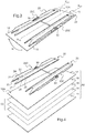
figure 3 est une vue en perspective de dessous d'un module photovoltaïque de lafigure 2 muni de profilés de renfort ; - la
figure 4 est une vue analogue à lafigure 3 , mais en perspective éclatée ; - la
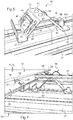
figure 5 est une vue à plus grande échelle du détail V de lafigure 2 ; - la
figure 6 est une coupe selon le plan VI de lafigure 2 ; et - la
figure 7 est une vue en perspective selon la flèche VII de lafigure 2 . - Sur la
figure 1 sont représentés des modules photovoltaïques 10, montés sur une structure porteuse 30 de type structure porteuse en plein champ. La structure 30 est adaptée pour recevoir les modules 10 avec une inclinaison de chaque module d'angle α par rapport à l'horizontale, prévue pour maximiser le rayonnement solaire incident sur le module. Sur lafigure 1 , les éléments de connectique et d'acheminement du courant électrique ont été omis pour une meilleure clarté du dessin. La structure 30 est une structure en acier inoxydable comprenant une pluralité de poutrelles 31, 33, 35 agencées entre elles de manière à former une charpente triangulée, sur laquelle sont fixées des traverses 37. Les traverses 37, dont on note X37 un axe longitudinal, sont parallèles entre elles et destinées à recevoir une pluralité de modules photovoltaïques 10 juxtaposés, chaque module photovoltaïque 10 étant monté sur la structure 30 au moyen d'un dispositif de fixation 1 conforme à l'invention. Dans l'exemple représenté sur les figures, chaque module 10 est pourvu sur sa face arrière 10A de deux profilés de renfort 20 et le dispositif de fixation 1 comprend, pour chaque module 10, quatre supports 40 solidaires de la structure. - Comme montré sur les
figures 3 et 4 , chaque module 10 de ce mode de réalisation est un module photovoltaïque dépourvu de cadre, qui comprend un substrat avant 11, un substrat arrière 12 et une ou plusieurs cellules photovoltaïques 13 intercalées entre les substrats avant 11 et arrière 12. Le substrat avant 11, destiné à être agencé du côté d'incidence du rayonnement solaire sur le module 10, est transparent, par exemple constitué en un verre transparent extra-clair ou en un polymère thermoplastique transparent tel que le polycarbonate, le polyuréthane ou le polyméthacrylate de méthyle. Le substrat arrière 12, destiné à être agencé en regard de la structure 30, est constitué en tout matériau approprié, transparent ou non, notamment en verre. - La ou chaque cellule photovoltaïque 13 positionnée entre les substrats 11 et 12 est formée par un empilement de couches minces comprenant successivement, à partir du substrat avant 11, une couche 14 transparente électriquement conductrice, notamment à base d'oxyde conducteur transparent (Transparent Conductive Oxide ou TCO), qui forme une électrode avant de la cellule ; une couche 15 d'absorbeur, propre à assurer la conversion de l'énergie issue du rayonnement solaire incident sur la cellule en énergie électrique, notamment une couche mince à base de silicium, amorphe ou microcristallin, ou à base de tellurure de cadmium; et une couche 16 électriquement conductrice qui forme une électrode arrière de la cellule.
- En variante, la couche 15 d'absorbeur de la ou chaque cellule 13 peut être une couche mince de composé chalcopyrite comportant du cuivre, de l'indium et du sélénium, dite couche d'absorbeur CIS, éventuellement additionnée de gallium (couche d'absorbeur CIGS), d'aluminium ou de soufre. Dans ce cas, la ou chaque cellule 13 à couches minces comprend un empilement analogue à celui décrit ci-dessus, un intercalaire de feuilletage polymère non représenté étant en outre positionné entre l'électrode avant 14 de la cellule et le substrat avant 11, afin de garantir une bonne cohésion du module 10 lors de son assemblage. L'intercalaire de feuilletage peut notamment être constitué en polybutyral de vinyle (PVB) ou en éthylène vinylacétate (EVA).
- Selon encore une autre variante, la ou chaque cellule 13 peut être constituée à partir de « wafers » ou galettes de silicium polycristallin ou monocristallin formant une jonction p/n.
- Comme visible sur la
figure 2 , chaque module 10 comporte deux profilés de renfort 20 solidaires de sa face arrière 10A destinée à être en regard de la structure 30, qui est la face du substrat arrière 12 opposée à la ou chaque cellule photovoltaïque 13. Chaque profilé de renfort 20 est de forme allongée d'axe longitudinal X20 et est adapté pour coopérer par encliquetage avec un support 40 au niveau de chacune de ses extrémités 20A et 20B. Les quatre supports 40 de réception d'un module 10 sont répartis par paires sur deux traverses 37 voisines, de telle sorte qu'en configuration encliquetée des deux profilés 20 du module sur les quatre supports 40 correspondants, l'axe longitudinal X20 de chaque profilé 20 est orienté transversalement par rapport à l'axe X37 des traverses 37. Lorsque chacun des deux profilés de renfort 20 d'un module 10 coopère par encliquetage avec deux supports 40, le module 10 est immobilisé par rapport à la structure 30. - De manière avantageuse, comme montré sur la
figure 3 , les deux profilés de renfort 20 de chaque module 10 sont disposés sur la face arrière 10A du module avec leurs axes longitudinaux X20 parallèles entre eux et à deux bords périphériques 18 opposés du module, de sorte que, lorsque le module 10 est monté sur la structure 30, les profilés 20 s'étendent perpendiculairement aux traverses 37. Un tel agencement favorise les mouvements de convection d'air à l'arrière du module 10, et donc le refroidissement du module. De préférence, chaque profilé 20 est décalé intérieurement par rapport au bord latéral 18 correspondant du module 10, de manière à renforcer la structure du module et à améliorer sa résistance mécanique. - Dans ce mode de réalisation, chaque profilé de renfort 20 d'un module 10 est constitué en acier inoxydable et formé à partir d'un unique flan découpé et plié. Chaque profilé 20 a une section transversale globalement en forme de deux omégas imbriqués l'un dans l'autre. Plus précisément, chaque oméga 21-25 ou 23-27 comprend deux branches, 21, 25 ou 23, 27, qui encadrent une partie centrale 22-24 ou 24-26 de l'oméga. Chaque partie centrale 22-24 ou 24-26 comporte une paroi de fond et deux parois latérales obliques par rapport à la paroi de fond, les deux omégas étant imbriqués de telle sorte que le fond 23 ou 25 de la partie centrale d'un oméga forme une branche de l'autre oméga. Les parois 21, 23, 25 et 27 du profilé 20, qui forment les fonds et les branches des omégas, sont sensiblement planes et destinées à venir en regard, respectivement, de la face arrière 10A du module 10, pour les parois 23 et 27, et de la structure 30, pour les parois 21 et 25.
- Les deux profilés de renfort 20 de chaque module 10 sont solidarisés directement avec la face arrière 10A du module par collage des parois 23 et 27 contre la face 10A, au moyen d'un matériau adhésif. Comme visible sur les
figures 3 et 4 , les parois 21 et 22 de chaque profilé 20 délimitent une échancrure 20C au niveau d'une portion médiane du profilé par rapport à sa direction longitudinale. Cette échancrure 20C est obtenue par découpe du flan constitutif du profilé 20, avant pliage de ce flan. L'échancrure 20C de chaque profilé 20 crée un évidement de matière permettant la mise en place d'une boîte de connexion 50 sur la face 10A arrière du module. Chaque module est ainsi équipé de deux boîtes de connexion 50, logées chacune au niveau de l'échancrure 20C d'un profilé 20. Les boîtes de connexion 50 d'un module 10 sont reliées entre elles et avec l'extérieur au moyen de câbles 52, ce qui permet le raccordement électrique du module 10, une fois monté sur la structure 30, avec des modules 10 adjacents et des dispositifs non représentés de mise à disposition de courant électrique. - De manière particulièrement avantageuse, les deux profilés de renfort 20 d'un module 10 sont identiques l'un à l'autre et agencés sur la face arrière 10A du module de manière symétrique l'un de l'autre par rapport à un axe médian X10 du module. En particulier, comme montré par la flèche R de la
figure 3 , il suffit de procéder à une rotation de 180° d'un profilé 20 sur lui-même pour réaliser le positionnement des deux profilés 20 sur la face 10A, à partir d'un modèle unique de profilé. Il en résulte la possibilité de produire le profilé 20 en grande série, par découpe et pliage de flans en acier, et ainsi de réduire son coût de fabrication. En variante, les profilés 20 peuvent être constitués en tout matériau autre que l'acier et adapté à leur fonction, notamment en un autre matériau métallique ou en un matériau synthétique, le profilé étant dans ce dernier cas obtenu par extrusion du matériau synthétique. - Chaque support 40 du dispositif de fixation 1 est fixé sur la traverse 37 correspondante au moyen de deux vis 39. Chaque support 40 est constitué en acier inoxydable et formé à partir d'un unique flan plié et découpé. Les supports 40 sont identiques entre eux et présentent chacun une section transversale globalement en forme d'oméga, comprenant deux branches 41 et 45 qui encadrent une partie centrale 42-44 de l'oméga. La partie centrale de l'oméga comporte une paroi de fond 43 et deux parois latérales 42 et 44 obliques par rapport à la paroi de fond 43. Comme montré sur la
figure 6 , cette partie centrale 42-44 de chaque support 40 est prévue avec une section transversale en U sensiblement complémentaire de la section transversale en U de la partie 22-24 de chaque profilé 20. En particulier, la partie 22-24 de chaque profilé 20 du module est apte à venir coiffer simultanément la partie centrale 42-44 de deux supports 40 agencés sur deux traverses 37 voisines, comme montré sur lafigure 7 . La paroi de fond 43 de chaque support 40 est équipée de butées élastiques 47, destinées à recevoir en appui la paroi 23 d'un profilé 20 coiffant le support. - Afin de garantir un positionnement optimal d'un module 10 par rapport à la structure 30 en vue de la fixation du module sur la structure, au moins l'un des quatre supports 40 associés au module est muni d'un pion d'alignement 451, au niveau de sa paroi 45. Ce pion 451 est destiné à coopérer avec un orifice 251 complémentaire prévu dans la paroi 25 d'au moins un profilé de renfort 20 du module, au voisinage de l'extrémité 20A ou 20B du profilé. La coopération entre le pion d'alignement 451 et l'orifice 251 correspondant, combinée à la venue en prise relative des parties en U 22-24 des profilés et 42-44 des supports, permet une indexation fiable de la position du module sur la structure préalablement à leur immobilisation relative, ce qui contribue à faciliter le montage du module sur la structure.
- Pour la fixation des modules 10 sur la structure 30, la paroi latérale 42 de chaque support 40 comporte une languette 48 prévue pour coopérer par encliquetage avec une encoche 28 ménagée dans la paroi latérale 22 de chaque profilé de renfort 20. Plus précisément, comme visible sur la
figure 2 , la paroi latérale 22 de chaque profilé 20 comporte deux encoches 28, disposées chacune au voisinage d'une extrémité 20A, 20B du profilé. Ainsi, lorsque la partie 22-24 d'un profilé de renfort 20 coiffe simultanément la partie 42-44 de deux supports 40 agencés sur deux traverses 37 voisines, la languette 48 de chacun des deux supports 40 est apte à s'encliqueter dans l'une des deux encoches 28 du profilé. Dans l'état encliqueté d'une languette 48 par rapport à une encoche 28, un bord inférieur 281 de l'encoche est reçu dans une rainure 49 délimitée par la languette 48 et ouverte en direction de la structure 30. Dans ce mode de réalisation, la fixation de chaque module 10 sur la structure 30 met en jeu l'encliquetage des languettes 48 de quatre supports 40 dans quatre encoches 28, réparties par paires sur les deux profilés de renfort 20 du module. Dans l'état activé des moyens d'encliquetage que constituent ces quatre couples de languettes 48 et encoches 28, les deux profilés de renfort 20 du module 10 sont immobilisés par rapport aux quatre supports 40, de sorte que le module 10 est fixé par rapport à la structure 30. - La paroi latérale 42 de chaque support 40 comporte également, de part et d'autre de la languette 48, deux lames élastiques 46 découpées dans la structure en acier du support 40. Deux lames élastiques 46 sont également découpées dans la paroi latérale 44 de chaque support 40, de manière symétrique par rapport à un plan médian du support. Les quatre lames élastiques 46 sont propres à exercer, sur les parois 22 et 24 d'un profilé 20 coiffant le support 40, un effort de poussée du profilé 20 à l'écart du support 40, et donc du module 10 à l'écart de la structure 30, comme montré par la flèche P de la
figure 6 . L'effort de poussée P exercé par les lames élastiques 46 sur le profilé de renfort 20 permet un verrouillage des moyens d'encliquetage 28 et 48 dans leur état activé, en maintenant le bord 281 de l'encoche 28 à l'intérieur de la rainure 49. - Outre les deux encoches 28, la paroi latérale 22 de chaque profilé de renfort 20 d'un module 10 comporte également deux orifices 29, situés chacun au voisinage de l'une des encoches 28 de telle sorte que, dans la configuration encliquetée d'une languette 48 par rapport à l'encoche 28, l'orifice 29 est en regard de la languette 48. Grâce à cet agencement, il est possible de désactiver les moyens d'encliquetage d'un module 10 monté sur la structure 30, c'est-à-dire de déverrouiller l'assemblage. Comme montré sur la
figure 7 , un tel déverrouillage est obtenu en appliquant à la fois un effort F2 de poussée du module 10 en direction de la structure 30, à l'encontre de la poussée élastique P des lames 46, et un effort F3 de poussée de chaque languette 48 coopérant avec un profilé de renfort du module 10 à l'écart de l'encoche 28 correspondante. L'effort de poussée F3 est exercé à travers l'orifice 29 voisin de l'encoche 28, à l'aide de tout outil approprié. - Un procédé de montage de modules photovoltaïques 10 sur la structure 30 au moyen du dispositif de fixation 1 conforme à l'invention comprend des étapes telles que décrites ci-après.
- Tout d'abord, on équipe le module 10 avec ses deux profilés de renfort 20, par collage des parois 23 et 27 des profilés de renfort contre la face 10A du module, selon l'agencement montré sur la
figure 3 . - On solidarise également des supports 40 avec la structure 30, par vissage au moyen de vis 39, en disposant les supports 40 sur les traverses 37 de la structure avec un espacement approprié, correspondant à l'espacement entre les encoches 28 des profilés de renfort 20.
- Le montage de chaque module 10 sur la structure 30 s'opère ensuite de la façon suivante. Dans un premier temps, on aligne mutuellement les moyens d'encliquetage 28 et 48. A cet effet, on met en prise la partie centrale en U 42-44 de deux supports 40 agencés sur deux traverses 37 voisines, à l'intérieur de la partie en U 22-24 correspondante de chacun des deux profilés de renfort 20 du module 10. Ce faisant, on introduit également le pion d'alignement 451, prévu sur au moins l'un des quatre supports 40 associés au module 10, dans l'orifice 251 correspondant d'au moins un profilé de renfort 20 du module 10. A l'issue de cette étape, les languettes 48 et encoches 28 formant moyens d'encliquetage sont alignées deux à deux. On applique alors un effort unidirectionnel F1 de poussée du module 10 en direction de la structure 30, de manière à activer les moyens d'encliquetage, c'est-à-dire à encliqueter la languette 48 de chacun des quatre supports 40 associés au module dans l'encoche 28 qui est alignée avec la languette.
- De manière avantageuse, l'étape de solidarisation des profilés de renfort 20 avec les modules 10 peut être réalisée sur le site de fabrication des modules 10, alors que les étapes suivantes sont réalisées sur le site de montage des modules 10.
- Dans le cas où il est nécessaire de retirer ou de remplacer un module 10 monté sur la structure 30, par exemple en cas de panne de ce module, le démontage du module 10 s'opère de manière particulièrement simple, en appliquant simultanément un effort F2 de poussée du module 10 en direction de la structure 30, à l'encontre de la poussée élastique P des lames 46, et un effort F3 de poussée de chaque languette 48 coopérant avec un profilé de renfort du module 10 à l'écart de l'encoche 28 correspondante, à travers l'orifice 29 voisin de l'encoche 28.
- Comme il ressort du mode de réalisation décrit précédemment, le dispositif de fixation conforme à l'invention permet un montage rapide et aisé de modules solaires sur une structure, telle qu'une structure porteuse en plein champ, par l'application d'un effort F1 unidirectionnel de poussée sur chaque module préalablement positionné sur la structure, sans nécessiter d'outillage particulier. Cet effort de poussée actionne l'encliquetage de profilés de renfort du module par rapport à des supports solidaires de la structure. Le positionnement du module sur la structure pour l'alignement préalable des moyens d'encliquetage des supports par rapport aux profilés de renfort est également aisé, en particulier grâce à la forme complémentaire de certaines parties 22-24 et 42-44 des profilés de renfort 20 et des supports 40.
- Grâce à l'action élastique des moyens de verrouillage 46, qui maintiennent les moyens d'encliquetage dans un état activé, la fixation obtenue des modules sur la structure est fiable et robuste. De plus, les éléments constitutifs du dispositif de fixation conforme à l'invention, à savoir les profilés de renfort 20 et les supports 40, présentent l'avantage de pouvoir être fabriqués de manière simple et économique, par pliage et découpe de flans en acier, de façon à définir les moyens d'encliquetage et de verrouillage. En outre, l'assemblage des modules avec la structure obtenu selon l'invention est réversible, grâce à la présence des orifices de déverrouillage 29, qui permettent un démontage individuel d'un module par rapport à la structure, en cas de panne de ce module.
- Par ailleurs, la présence des profilés de renfort 20 de forme allongée, régulièrement répartis à l'arrière de chaque module, améliore la résistance mécanique des modules et, dans la mesure où il n'est plus nécessaire d'avoir un cadre autour de la périphérie du module pour obtenir sa fixation sur une structure, toute la surface active du module est exposée au rayonnement solaire, ce qui garantit un rendement optimal du module.
- L'invention n'est pas limitée aux exemples décrits et représentés. En particulier, l'arrangement selon l'invention peut mettre en jeu des organes d'encliquetage autres que des languettes et encoches, ou encore un nombre d'encoches et de languettes différents de ce qui a été décrit précédemment. Le nombre et la forme des profilés de renfort 20 associés à chaque module peuvent également être différents de ceux décrits précédemment, les profilés de renfort étant avantageusement répartis régulièrement sur la face 10A du module de manière à renforcer la structure du module. De plus, l'arrangement selon l'invention peut être mis en œuvre pour le montage sur une structure de modules équipés ou non de cadres périphériques, l'option sans cadre étant toutefois préférée. L'arrangement selon l'invention peut également être utilisé pour le montage de modules solaires de tout type, sur une structure de réception également de tout type. En particulier, les modules solaires photovoltaïques décrits précédemment peuvent être remplacés par des modules solaires thermiques ou mixtes photovoltaïques/thermiques, et la structure de réception peut être indifféremment une structure porteuse en plein champ, un toit ou une façade.
Claims (12)
- Arrangement comprenant:- un dispositif (1) de fixation d'un module (10) de récupération d'énergie issue du rayonnement solaire sur une structure (30), telle qu'un toit, une façade ou une structure porteuse en plein champ,- un module (10) de récupération d'énergie issue du rayonnement solaire,où le module (10) est pourvu sur sa face arrière (10A) d'au moins un profilé de renfort (20), où le au moins un profilé de renfort (20) est décalé intérieurement par rapport aux bords périphériques (18) du module (10) et où le dispositif de fixation comprend au moins un support (40) solidaire de la structure (30), ce au moins un support (40) comportant des moyens (48) d'encliquetage par rapport au profilé de renfort (20) du module, qui sont aptes à être activés par l'application d'un effort unidirectionnel (F1) de poussée du module (10) en direction de la structure (30), caractérisé en ce que le au moins un support (40) comporte, pour le verrouillage des moyens d'encliquetage dans leur état activé, des moyens élastiques (46) de poussée (P) du module (10) à l'écart de la structure (30).
- Arrangement selon la revendication 1, caractérisé en ce que les moyens d'encliquetage comprennent au moins une languette (48) du support (40) propre à coopérer par encliquetage avec une encoche (28) du profilé de renfort (20).
- Arrangement selon la revendication 2, caractérisé en ce que la languette (48) définit une rainure (49) de réception d'un bord (281) de l'encoche (28), cette rainure (49) étant ouverte en direction de la structure (30).
- Arrangement selon la revendication 3, caractérisé en ce qu'il comprend, en tant que moyens de verrouillage des moyens d'encliquetage dans leur état activé, des moyens élastiques (46) de poussée (P) du module (10) à l'écart de la structure (30) pour le maintien du bord (281) à l'intérieur de la rainure (49).
- Arrangement selon la revendication 4, caractérisé en ce que le profilé de renfort (20) comporte un orifice de déverrouillage (29) qui, dans l'état activé des moyens d'encliquetage, est en regard de la languette (48), les moyens d'encliquetage étant aptes à passer de leur état activé à un état désactivé sous l'effet combiné d'un effort (F2) de poussée du module (10) en direction de la structure (30) à l'encontre des moyens élastiques (46) et d'un effort (F3) de poussée de la languette (48) à l'écart de l'encoche (28) exercé à travers l'orifice de déverrouillage (29).
- Arrangement selon l'une quelconque des revendications précédentes, caractérisé en ce que le profilé de renfort (20) comporte au moins une partie (22-24) à section transversale en U sensiblement complémentaire de la section transversale en U d'une partie (42-44) du support (40), ces parties en U (22-24, 42-44) étant en prise l'une dans l'autre dans l'état activé des moyens d'encliquetage.
- Arrangement selon l'une quelconque des revendications précédentes, caractérisé en ce qu'il comprend au moins un pion (451) solidaire de l'un parmi le profilé de renfort (20) et le support (40), ce pion (451) étant propre à coopérer avec un orifice (251) de l'autre parmi le profilé de renfort (20) et le support (40) pour l'alignement des moyens d'encliquetage (48) du support (40) par rapport au profilé de renfort (20).
- Arrangement selon l'une quelconque des revendications précédentes, caractérisé en ce que le support (40) est un flan métallique plié et découpé pour former les moyens d'encliquetage.
- Arrangement selon l'une quelconque des revendications précédentes, caractérisé en ce que le profilé de renfort (20) du module est de forme allongée et adapté pour coopérer par encliquetage avec un support (40) au niveau de chacune de ses extrémités (20A, 20B).
- Arrangement selon l'une quelconque des revendications précédentes, caractérisé en ce que le module (10) comprend au moins deux profilés de renfort (20) solidaires de sa face arrière (10A) et régulièrement répartis sur ladite face arrière (10A).
- Arrangement selon l'une quelconque des revendications précédentes, caractérisé en ce que le module (10) est un module photovoltaïque dépourvu de cadre, qui comprend un substrat avant (11), un substrat arrière (12) et au moins une cellule photovoltaïque (13) intercalée entre les substrats avant (11) et arrière (12), le ou chaque profilé de renfort (20) étant solidaire d'une face arrière (10A) du substrat arrière (12) opposée à la cellule photovoltaïque (13).
- Procédé de montage d'un arrangement selon l'une quelconque des revendications précédentes, caractérisé en ce qu'il comprend des étapes dans lesquelles :- on solidarise au moins un support (40) avec la structure (30) ;- on aligne les moyens d'encliquetage (48) du support (40) par rapport au profilé de renfort (20) ;- on active les moyens d'encliquetage (28, 48) par l'application d'un effort unidirectionnel (F1) de poussée du module (10) en direction de la structure (30).
Applications Claiming Priority (2)
| Application Number | Priority Date | Filing Date | Title |
|---|---|---|---|
| FR0953119A FR2945609B1 (fr) | 2009-05-12 | 2009-05-12 | Dispositif de fixation et procede de montage de modules solaires. |
| PCT/FR2010/050922 WO2010130952A2 (fr) | 2009-05-12 | 2010-05-12 | Dispositif de fixation et procede de montage de modules solaires |
Publications (2)
| Publication Number | Publication Date |
|---|---|
| EP2430378A2 EP2430378A2 (fr) | 2012-03-21 |
| EP2430378B1 true EP2430378B1 (fr) | 2021-10-27 |
Family
ID=41426927
Family Applications (1)
| Application Number | Title | Priority Date | Filing Date |
|---|---|---|---|
| EP10728747.6A Active EP2430378B1 (fr) | 2009-05-12 | 2010-05-12 | Arrangement comprenant un dispositif de fixation et procede de montage de cet arrangement |
Country Status (8)
| Country | Link |
|---|---|
| US (1) | US8763346B2 (fr) |
| EP (1) | EP2430378B1 (fr) |
| JP (1) | JP5934091B2 (fr) |
| KR (1) | KR101768728B1 (fr) |
| CN (1) | CN102597655B (fr) |
| ES (1) | ES2904687T3 (fr) |
| FR (1) | FR2945609B1 (fr) |
| WO (1) | WO2010130952A2 (fr) |
Families Citing this family (30)
| Publication number | Priority date | Publication date | Assignee | Title |
|---|---|---|---|---|
| DE202010005576U1 (de) * | 2010-06-07 | 2010-09-02 | SCHÜCO International KG | Wandkonstruktion |
| US20120145848A1 (en) * | 2010-12-10 | 2012-06-14 | David Schuff | Pier cap cleat |
| WO2012115544A1 (fr) * | 2011-02-21 | 2012-08-30 | Sapa Profiler Ab | Châssis de construction et procédé pour le montage de modules solaires sur une sous-structure |
| CN103688115A (zh) * | 2011-06-02 | 2014-03-26 | 道康宁公司 | 光伏模块组件及其组装方法 |
| EP2817831B1 (fr) * | 2012-02-24 | 2020-12-23 | Solvay Specialty Polymers USA, LLC. | Structure d'encadrement pour panneau solaire |
| CA2860607A1 (fr) * | 2012-03-15 | 2013-09-19 | Magna International Inc. | Structure de montage de panneau solaire |
| CN102709353A (zh) * | 2012-05-16 | 2012-10-03 | 李莉 | 一种太阳能电池板支架 |
| US9316417B2 (en) * | 2012-06-29 | 2016-04-19 | Sunpower Corporation | Framing system for mounting solar collecting devices |
| US8936164B2 (en) | 2012-07-06 | 2015-01-20 | Industrial Origami, Inc. | Solar panel rack |
| US10135386B2 (en) | 2012-10-12 | 2018-11-20 | Smash Solar, Inc. | Sensing, interlocking solar module system and installation method |
| JP2014196613A (ja) * | 2013-03-29 | 2014-10-16 | ホリー株式会社 | ソーラーパネル用架台及びその施工方法 |
| JP2014196612A (ja) * | 2013-03-29 | 2014-10-16 | ホリー株式会社 | ソーラーパネル用架台及びその施工方法 |
| FR3005951B1 (fr) * | 2013-05-24 | 2015-05-01 | Saint Gobain Isover | Dispositif pour la fabrication d'un produit fibreux |
| US9166526B2 (en) * | 2013-07-03 | 2015-10-20 | Industrial Origami, Inc. | Solar panel rack |
| US10171027B2 (en) * | 2015-03-02 | 2019-01-01 | Sunpower Corporation | Photovoltaic module mount |
| US20200266757A1 (en) * | 2015-08-11 | 2020-08-20 | Smash Solar, Inc. | Interlocking, Preassembled Solar Panel Module System and Installation Method |
| ES2988892T3 (es) * | 2015-12-15 | 2024-11-22 | Ml System Spolka Akcyjna | Conjunto de elementos estructurales adecuados para conectar de forma desmontable un módulo fotovoltaico de una fachada ventilada a una pared frontal aislada de un edificio |
| CN105834188B (zh) * | 2016-05-13 | 2017-03-22 | 北京中电博顺智能设备技术有限公司 | 一种光伏板清洗设备 |
| US9923513B2 (en) * | 2016-05-13 | 2018-03-20 | Boson Robotics Ltd. | Cleaning mechanism having water spray function and photovoltaic panel cleaning equipment having same |
| JP6542161B2 (ja) * | 2016-06-28 | 2019-07-10 | 株式会社サンレール | 太陽光発電パネル架台 |
| JP6592407B2 (ja) * | 2016-06-28 | 2019-10-16 | 株式会社サンレール | 太陽光発電パネル架台 |
| US11139776B2 (en) * | 2016-07-01 | 2021-10-05 | Sunpower Corporation | Photovoltaic panel having a distributed support frame |
| US10490682B2 (en) | 2018-03-14 | 2019-11-26 | National Mechanical Group Corp. | Frame-less encapsulated photo-voltaic solar panel supporting solar cell modules encapsulated within multiple layers of optically-transparent epoxy-resin materials |
| US10602841B2 (en) * | 2018-04-05 | 2020-03-31 | Todd Hawkinson | Video screen holding assembly |
| US11502638B2 (en) * | 2018-05-04 | 2022-11-15 | Nextracker Llc | Solar module mounting system |
| TWM569526U (zh) * | 2018-07-03 | 2018-11-01 | 景欣有限公司 | 型鋼支撐件 |
| US11725876B2 (en) * | 2019-08-21 | 2023-08-15 | Rasp, Llc | Modular, portable cold room storage system |
| US11999284B2 (en) | 2021-09-01 | 2024-06-04 | Terabase Energy, Inc. | Solar table mobile transport |
| US11938576B1 (en) | 2022-12-20 | 2024-03-26 | Terabase Energy, Inc. | Systems and methods for threading a torque tube through U-bolt and module rail devices |
| US12368404B2 (en) * | 2023-01-18 | 2025-07-22 | Imam Abdulrahman Bin Faisal University | Dual-function racking structure for natural cooling of photovoltaic panels |
Family Cites Families (24)
| Publication number | Priority date | Publication date | Assignee | Title |
|---|---|---|---|---|
| US4254813A (en) * | 1979-06-20 | 1981-03-10 | Hunter Douglas International N.V. | Valance bracket for vertical venetian blind |
| JPS61130409U (fr) * | 1985-02-04 | 1986-08-15 | ||
| JPS6219326U (fr) * | 1985-07-19 | 1987-02-05 | ||
| US4677248A (en) * | 1985-09-13 | 1987-06-30 | Lacey Thomas G | Apparatus for mounting solar cells |
| JPH04269261A (ja) * | 1991-02-25 | 1992-09-25 | Inax Corp | 紙貼りタイルユニットの製造に用いる目地板の固定方法 |
| US5876084A (en) * | 1997-07-15 | 1999-03-02 | Prince Corporation | Panel mounting clip |
| AUPP558698A0 (en) * | 1998-08-31 | 1998-09-24 | Pacific Solar Pty Limited | Frame for mounting a panel or the like to a roof |
| IT1310335B1 (it) * | 1999-02-17 | 2002-02-13 | Technogym Srl | Macchina ginnica migliorata per l'esercizio degli arti inferiori. |
| DE19934073B4 (de) * | 1999-07-19 | 2005-08-25 | Regen Energiesysteme Gmbh | Vorrichtung zur Befestigung von Solarmodulen |
| JP3529312B2 (ja) * | 1999-12-24 | 2004-05-24 | ニチハ株式会社 | 建築板の留め付け構造 |
| US6360491B1 (en) * | 2000-01-14 | 2002-03-26 | Stanley A. Ullman | Roof support system for a solar panel |
| US6672018B2 (en) * | 2001-10-12 | 2004-01-06 | Jefferson Shingleton | Solar module mounting method and clip |
| CA2543644A1 (fr) * | 2003-10-27 | 2005-05-06 | Astellas Pharma Inc. | Derives de pyrazine et utilisation pharmaceutique de ce derive |
| US7420177B2 (en) * | 2006-01-20 | 2008-09-02 | Evans & Sutherland Computer Corporation | High-resolution-imaging system for scanned-column projectors |
| DE202006018426U1 (de) * | 2006-12-04 | 2007-02-08 | Ideematec Deutschland Gmbh | Montageschienensystem |
| DE202007003060U1 (de) * | 2007-03-02 | 2008-07-17 | SCHÜCO International KG | Verbindungselement |
| FR2915217B1 (fr) * | 2007-04-20 | 2009-07-10 | Imphy Alloys Sa | Structure pour le montage dans une paroi d'un batiment de batis destines a supporter des panneaux tels que des panneaux photovoltaiques |
| DE102007027997B4 (de) * | 2007-06-14 | 2012-12-06 | Fath Gmbh Kunststoff- Und Stahltechnik | Befestigungseinrichtung für an einem Gestellaufbau anzuordnende flächige rahmenlose Bauteile, insbesondere Solarmodule |
| US8585000B2 (en) * | 2008-05-22 | 2013-11-19 | Mainstream Energy Corporation | Universal end clamp |
| DE102008027857A1 (de) | 2008-06-11 | 2009-03-05 | Leichtmetallbau Schletter Gmbh | Montagesystem für PV-Module |
| FR2939162A1 (fr) * | 2008-12-01 | 2010-06-04 | Saint Gobain | Toiture solaire |
| US8240109B2 (en) * | 2009-03-20 | 2012-08-14 | Northern States Metals Company | Support system for solar panels |
| US8191320B2 (en) * | 2009-10-15 | 2012-06-05 | Sunlink Corporation | Photovoltaic panel clamp |
| US8418983B2 (en) * | 2010-07-29 | 2013-04-16 | First Solar, Inc. | Slider clip and photovoltaic structure mounting system |
-
2009
- 2009-05-12 FR FR0953119A patent/FR2945609B1/fr active Active
-
2010
- 2010-05-12 EP EP10728747.6A patent/EP2430378B1/fr active Active
- 2010-05-12 ES ES10728747T patent/ES2904687T3/es active Active
- 2010-05-12 KR KR1020117029476A patent/KR101768728B1/ko active Active
- 2010-05-12 CN CN201080032195.8A patent/CN102597655B/zh active Active
- 2010-05-12 US US13/319,894 patent/US8763346B2/en active Active
- 2010-05-12 JP JP2012510346A patent/JP5934091B2/ja active Active
- 2010-05-12 WO PCT/FR2010/050922 patent/WO2010130952A2/fr not_active Ceased
Non-Patent Citations (1)
| Title |
|---|
| None * |
Also Published As
| Publication number | Publication date |
|---|---|
| WO2010130952A3 (fr) | 2011-12-29 |
| US8763346B2 (en) | 2014-07-01 |
| JP2012526933A (ja) | 2012-11-01 |
| WO2010130952A2 (fr) | 2010-11-18 |
| EP2430378A2 (fr) | 2012-03-21 |
| US20120085395A1 (en) | 2012-04-12 |
| CN102597655A (zh) | 2012-07-18 |
| CN102597655B (zh) | 2015-10-14 |
| KR101768728B1 (ko) | 2017-08-16 |
| JP5934091B2 (ja) | 2016-06-15 |
| ES2904687T3 (es) | 2022-04-05 |
| FR2945609B1 (fr) | 2013-03-29 |
| KR20120030085A (ko) | 2012-03-27 |
| FR2945609A1 (fr) | 2010-11-19 |
Similar Documents
| Publication | Publication Date | Title |
|---|---|---|
| EP2430378B1 (fr) | Arrangement comprenant un dispositif de fixation et procede de montage de cet arrangement | |
| FR2949494A1 (fr) | Dispositif de fixation et procede de montage de modules solaires | |
| EP2212919B1 (fr) | Perfectionnements apportés à des éléments capables de collecter de la lumière | |
| EP2452369B1 (fr) | Procédé de fabrication de cellules photovoltaiques multi-jonctions et multi-électrodes | |
| FR2651924A1 (fr) | Panneau solaire et procede pour assembler un tel panneau avec ses cellules et elements d'interconnexion. | |
| FR2487581A1 (fr) | Assemblage de cellules photovoltaiques et procede de fabrication d'un tel assemblage | |
| WO2015107293A1 (fr) | Centrale photovoltaïque mettant en œuvre des panneaux photovoltaïques supportés par des moyens flottants mettant en œuvre un ensemble de câbles | |
| EP2488802A2 (fr) | Dispositif conformé pour fixer à lui seul un panneau solaire à une seule poutre d'une structure porteuse et installation comprenant un tel dispositif | |
| EP3340318A1 (fr) | Dispositif photovoltaïque et procede de fabrication associe | |
| FR2965671A1 (fr) | Dispositif d'egalisation de potentiel de panneaux solaires. | |
| FR2952755A1 (fr) | Ensemble photovoltaique | |
| FR2997171A1 (fr) | Dispositif de fixation de tuiles solaires pour une toiture solaire | |
| US10707364B2 (en) | Solar cell with absorber substrate bonded between substrates | |
| EP3966928A2 (fr) | Element de montage de panneau photovoltaique en toiture | |
| WO2020229755A1 (fr) | Panneau photovoltaique | |
| WO2013004923A1 (fr) | Procédé de réalisation d'une cellule photovoltaïque à homojonction comprenant un film mince de passivation en oxyde cristallin de silicium. | |
| Schropp et al. | Technology of Solar Cells | |
| WO2017081400A1 (fr) | Structure électronique sur support en céramique |
Legal Events
| Date | Code | Title | Description |
|---|---|---|---|
| PUAI | Public reference made under article 153(3) epc to a published international application that has entered the european phase |
Free format text: ORIGINAL CODE: 0009012 |
|
| AK | Designated contracting states |
Kind code of ref document: A2 Designated state(s): AL AT BE BG CH CY CZ DE DK EE ES FI FR GB GR HR HU IE IS IT LI LT LU LV MC MK MT NL NO PL PT RO SE SI SK SM TR |
|
| AX | Request for extension of the european patent |
Extension state: BA ME RS |
|
| 17P | Request for examination filed |
Effective date: 20120629 |
|
| RBV | Designated contracting states (corrected) |
Designated state(s): AL AT BE BG CH CY CZ DE DK EE ES FI FR GB GR HR HU IE IS IT LI LT LU LV MC MK MT NL NO PL PT RO SE SI SK SM TR |
|
| DAX | Request for extension of the european patent (deleted) | ||
| 17Q | First examination report despatched |
Effective date: 20160518 |
|
| STAA | Information on the status of an ep patent application or granted ep patent |
Free format text: STATUS: EXAMINATION IS IN PROGRESS |
|
| RAP1 | Party data changed (applicant data changed or rights of an application transferred) |
Owner name: (CNBM) BENGBU DESIGN & RESEARCH INSTITUTE FOR GLAS |
|
| REG | Reference to a national code |
Ref country code: DE Ref legal event code: R079 Ref document number: 602010067727 Country of ref document: DE Free format text: PREVIOUS MAIN CLASS: F24J0002520000 Ipc: H02S0020230000 |
|
| GRAP | Despatch of communication of intention to grant a patent |
Free format text: ORIGINAL CODE: EPIDOSNIGR1 |
|
| STAA | Information on the status of an ep patent application or granted ep patent |
Free format text: STATUS: GRANT OF PATENT IS INTENDED |
|
| RIC1 | Information provided on ipc code assigned before grant |
Ipc: H02S 20/23 20140101AFI20201102BHEP Ipc: F24S 25/12 20180101ALI20201102BHEP Ipc: H01L 31/18 20060101ALI20201102BHEP Ipc: F24S 25/00 20180101ALI20201102BHEP Ipc: F24S 25/632 20180101ALI20201102BHEP Ipc: F24S 25/65 20180101ALI20201102BHEP Ipc: H02S 20/10 20140101ALI20201102BHEP Ipc: H02S 20/26 20140101ALI20201102BHEP Ipc: F24S 25/60 20180101ALI20201102BHEP |
|
| INTG | Intention to grant announced |
Effective date: 20201204 |
|
| GRAS | Grant fee paid |
Free format text: ORIGINAL CODE: EPIDOSNIGR3 |
|
| GRAA | (expected) grant |
Free format text: ORIGINAL CODE: 0009210 |
|
| STAA | Information on the status of an ep patent application or granted ep patent |
Free format text: STATUS: THE PATENT HAS BEEN GRANTED |
|
| AK | Designated contracting states |
Kind code of ref document: B1 Designated state(s): AL AT BE BG CH CY CZ DE DK EE ES FI FR GB GR HR HU IE IS IT LI LT LU LV MC MK MT NL NO PL PT RO SE SI SK SM TR |
|
| REG | Reference to a national code |
Ref country code: GB Ref legal event code: FG4D Free format text: NOT ENGLISH |
|
| REG | Reference to a national code |
Ref country code: CH Ref legal event code: EP |
|
| REG | Reference to a national code |
Ref country code: AT Ref legal event code: REF Ref document number: 1442756 Country of ref document: AT Kind code of ref document: T Effective date: 20211115 |
|
| REG | Reference to a national code |
Ref country code: DE Ref legal event code: R096 Ref document number: 602010067727 Country of ref document: DE |
|
| REG | Reference to a national code |
Ref country code: IE Ref legal event code: FG4D Free format text: LANGUAGE OF EP DOCUMENT: FRENCH |
|
| REG | Reference to a national code |
Ref country code: LT Ref legal event code: MG9D |
|
| REG | Reference to a national code |
Ref country code: NL Ref legal event code: MP Effective date: 20211027 |
|
| REG | Reference to a national code |
Ref country code: AT Ref legal event code: MK05 Ref document number: 1442756 Country of ref document: AT Kind code of ref document: T Effective date: 20211027 |
|
| REG | Reference to a national code |
Ref country code: ES Ref legal event code: FG2A Ref document number: 2904687 Country of ref document: ES Kind code of ref document: T3 Effective date: 20220405 |
|
| PG25 | Lapsed in a contracting state [announced via postgrant information from national office to epo] |
Ref country code: LT Free format text: LAPSE BECAUSE OF FAILURE TO SUBMIT A TRANSLATION OF THE DESCRIPTION OR TO PAY THE FEE WITHIN THE PRESCRIBED TIME-LIMIT Effective date: 20211027 Ref country code: FI Free format text: LAPSE BECAUSE OF FAILURE TO SUBMIT A TRANSLATION OF THE DESCRIPTION OR TO PAY THE FEE WITHIN THE PRESCRIBED TIME-LIMIT Effective date: 20211027 Ref country code: BG Free format text: LAPSE BECAUSE OF FAILURE TO SUBMIT A TRANSLATION OF THE DESCRIPTION OR TO PAY THE FEE WITHIN THE PRESCRIBED TIME-LIMIT Effective date: 20220127 Ref country code: AT Free format text: LAPSE BECAUSE OF FAILURE TO SUBMIT A TRANSLATION OF THE DESCRIPTION OR TO PAY THE FEE WITHIN THE PRESCRIBED TIME-LIMIT Effective date: 20211027 |
|
| PG25 | Lapsed in a contracting state [announced via postgrant information from national office to epo] |
Ref country code: IS Free format text: LAPSE BECAUSE OF FAILURE TO SUBMIT A TRANSLATION OF THE DESCRIPTION OR TO PAY THE FEE WITHIN THE PRESCRIBED TIME-LIMIT Effective date: 20220227 Ref country code: SE Free format text: LAPSE BECAUSE OF FAILURE TO SUBMIT A TRANSLATION OF THE DESCRIPTION OR TO PAY THE FEE WITHIN THE PRESCRIBED TIME-LIMIT Effective date: 20211027 Ref country code: PT Free format text: LAPSE BECAUSE OF FAILURE TO SUBMIT A TRANSLATION OF THE DESCRIPTION OR TO PAY THE FEE WITHIN THE PRESCRIBED TIME-LIMIT Effective date: 20220228 Ref country code: PL Free format text: LAPSE BECAUSE OF FAILURE TO SUBMIT A TRANSLATION OF THE DESCRIPTION OR TO PAY THE FEE WITHIN THE PRESCRIBED TIME-LIMIT Effective date: 20211027 Ref country code: NO Free format text: LAPSE BECAUSE OF FAILURE TO SUBMIT A TRANSLATION OF THE DESCRIPTION OR TO PAY THE FEE WITHIN THE PRESCRIBED TIME-LIMIT Effective date: 20220127 Ref country code: NL Free format text: LAPSE BECAUSE OF FAILURE TO SUBMIT A TRANSLATION OF THE DESCRIPTION OR TO PAY THE FEE WITHIN THE PRESCRIBED TIME-LIMIT Effective date: 20211027 Ref country code: LV Free format text: LAPSE BECAUSE OF FAILURE TO SUBMIT A TRANSLATION OF THE DESCRIPTION OR TO PAY THE FEE WITHIN THE PRESCRIBED TIME-LIMIT Effective date: 20211027 Ref country code: HR Free format text: LAPSE BECAUSE OF FAILURE TO SUBMIT A TRANSLATION OF THE DESCRIPTION OR TO PAY THE FEE WITHIN THE PRESCRIBED TIME-LIMIT Effective date: 20211027 Ref country code: GR Free format text: LAPSE BECAUSE OF FAILURE TO SUBMIT A TRANSLATION OF THE DESCRIPTION OR TO PAY THE FEE WITHIN THE PRESCRIBED TIME-LIMIT Effective date: 20220128 |
|
| REG | Reference to a national code |
Ref country code: DE Ref legal event code: R097 Ref document number: 602010067727 Country of ref document: DE |
|
| PG25 | Lapsed in a contracting state [announced via postgrant information from national office to epo] |
Ref country code: SM Free format text: LAPSE BECAUSE OF FAILURE TO SUBMIT A TRANSLATION OF THE DESCRIPTION OR TO PAY THE FEE WITHIN THE PRESCRIBED TIME-LIMIT Effective date: 20211027 Ref country code: SK Free format text: LAPSE BECAUSE OF FAILURE TO SUBMIT A TRANSLATION OF THE DESCRIPTION OR TO PAY THE FEE WITHIN THE PRESCRIBED TIME-LIMIT Effective date: 20211027 Ref country code: RO Free format text: LAPSE BECAUSE OF FAILURE TO SUBMIT A TRANSLATION OF THE DESCRIPTION OR TO PAY THE FEE WITHIN THE PRESCRIBED TIME-LIMIT Effective date: 20211027 Ref country code: EE Free format text: LAPSE BECAUSE OF FAILURE TO SUBMIT A TRANSLATION OF THE DESCRIPTION OR TO PAY THE FEE WITHIN THE PRESCRIBED TIME-LIMIT Effective date: 20211027 Ref country code: DK Free format text: LAPSE BECAUSE OF FAILURE TO SUBMIT A TRANSLATION OF THE DESCRIPTION OR TO PAY THE FEE WITHIN THE PRESCRIBED TIME-LIMIT Effective date: 20211027 Ref country code: CZ Free format text: LAPSE BECAUSE OF FAILURE TO SUBMIT A TRANSLATION OF THE DESCRIPTION OR TO PAY THE FEE WITHIN THE PRESCRIBED TIME-LIMIT Effective date: 20211027 |
|
| PLBE | No opposition filed within time limit |
Free format text: ORIGINAL CODE: 0009261 |
|
| STAA | Information on the status of an ep patent application or granted ep patent |
Free format text: STATUS: NO OPPOSITION FILED WITHIN TIME LIMIT |
|
| 26N | No opposition filed |
Effective date: 20220728 |
|
| PG25 | Lapsed in a contracting state [announced via postgrant information from national office to epo] |
Ref country code: AL Free format text: LAPSE BECAUSE OF FAILURE TO SUBMIT A TRANSLATION OF THE DESCRIPTION OR TO PAY THE FEE WITHIN THE PRESCRIBED TIME-LIMIT Effective date: 20211027 |
|
| PG25 | Lapsed in a contracting state [announced via postgrant information from national office to epo] |
Ref country code: SI Free format text: LAPSE BECAUSE OF FAILURE TO SUBMIT A TRANSLATION OF THE DESCRIPTION OR TO PAY THE FEE WITHIN THE PRESCRIBED TIME-LIMIT Effective date: 20211027 |
|
| REG | Reference to a national code |
Ref country code: CH Ref legal event code: PL |
|
| REG | Reference to a national code |
Ref country code: BE Ref legal event code: MM Effective date: 20220531 |
|
| PG25 | Lapsed in a contracting state [announced via postgrant information from national office to epo] |
Ref country code: MC Free format text: LAPSE BECAUSE OF FAILURE TO SUBMIT A TRANSLATION OF THE DESCRIPTION OR TO PAY THE FEE WITHIN THE PRESCRIBED TIME-LIMIT Effective date: 20211027 Ref country code: LU Free format text: LAPSE BECAUSE OF NON-PAYMENT OF DUE FEES Effective date: 20220512 Ref country code: LI Free format text: LAPSE BECAUSE OF NON-PAYMENT OF DUE FEES Effective date: 20220531 Ref country code: CH Free format text: LAPSE BECAUSE OF NON-PAYMENT OF DUE FEES Effective date: 20220531 |
|
| REG | Reference to a national code |
Ref country code: FR Ref legal event code: PLFP Year of fee payment: 14 |
|
| PG25 | Lapsed in a contracting state [announced via postgrant information from national office to epo] |
Ref country code: IE Free format text: LAPSE BECAUSE OF NON-PAYMENT OF DUE FEES Effective date: 20220512 |
|
| PG25 | Lapsed in a contracting state [announced via postgrant information from national office to epo] |
Ref country code: BE Free format text: LAPSE BECAUSE OF NON-PAYMENT OF DUE FEES Effective date: 20220531 |
|
| PG25 | Lapsed in a contracting state [announced via postgrant information from national office to epo] |
Ref country code: HU Free format text: LAPSE BECAUSE OF FAILURE TO SUBMIT A TRANSLATION OF THE DESCRIPTION OR TO PAY THE FEE WITHIN THE PRESCRIBED TIME-LIMIT; INVALID AB INITIO Effective date: 20100512 |
|
| PG25 | Lapsed in a contracting state [announced via postgrant information from national office to epo] |
Ref country code: MK Free format text: LAPSE BECAUSE OF FAILURE TO SUBMIT A TRANSLATION OF THE DESCRIPTION OR TO PAY THE FEE WITHIN THE PRESCRIBED TIME-LIMIT Effective date: 20211027 Ref country code: CY Free format text: LAPSE BECAUSE OF FAILURE TO SUBMIT A TRANSLATION OF THE DESCRIPTION OR TO PAY THE FEE WITHIN THE PRESCRIBED TIME-LIMIT Effective date: 20211027 |
|
| PG25 | Lapsed in a contracting state [announced via postgrant information from national office to epo] |
Ref country code: TR Free format text: LAPSE BECAUSE OF FAILURE TO SUBMIT A TRANSLATION OF THE DESCRIPTION OR TO PAY THE FEE WITHIN THE PRESCRIBED TIME-LIMIT Effective date: 20211027 |
|
| PG25 | Lapsed in a contracting state [announced via postgrant information from national office to epo] |
Ref country code: MT Free format text: LAPSE BECAUSE OF FAILURE TO SUBMIT A TRANSLATION OF THE DESCRIPTION OR TO PAY THE FEE WITHIN THE PRESCRIBED TIME-LIMIT Effective date: 20211027 |
|
| PGFP | Annual fee paid to national office [announced via postgrant information from national office to epo] |
Ref country code: DE Payment date: 20250530 Year of fee payment: 16 |
|
| PGFP | Annual fee paid to national office [announced via postgrant information from national office to epo] |
Ref country code: ES Payment date: 20250627 Year of fee payment: 16 |
|
| PGFP | Annual fee paid to national office [announced via postgrant information from national office to epo] |
Ref country code: IT Payment date: 20250429 Year of fee payment: 16 |
|
| PGFP | Annual fee paid to national office [announced via postgrant information from national office to epo] |
Ref country code: FR Payment date: 20250423 Year of fee payment: 16 |
|
| PGFP | Annual fee paid to national office [announced via postgrant information from national office to epo] |
Ref country code: GB Payment date: 20260331 Year of fee payment: 17 |