EP2432079A1 - Anschlussstück, Buchsenanschlussstück und Verfahren zur Herstellung eines elektrischen Kontakts eines Anschlussstücks - Google Patents
Anschlussstück, Buchsenanschlussstück und Verfahren zur Herstellung eines elektrischen Kontakts eines Anschlussstücks Download PDFInfo
- Publication number
- EP2432079A1 EP2432079A1 EP11009725A EP11009725A EP2432079A1 EP 2432079 A1 EP2432079 A1 EP 2432079A1 EP 11009725 A EP11009725 A EP 11009725A EP 11009725 A EP11009725 A EP 11009725A EP 2432079 A1 EP2432079 A1 EP 2432079A1
- Authority
- EP
- European Patent Office
- Prior art keywords
- tab
- guiding
- contact
- terminal fitting
- main portion
- Prior art date
- Legal status (The legal status is an assumption and is not a legal conclusion. Google has not performed a legal analysis and makes no representation as to the accuracy of the status listed.)
- Granted
Links
- 238000000034 method Methods 0.000 title description 10
- 238000003780 insertion Methods 0.000 description 14
- 230000037431 insertion Effects 0.000 description 14
- 238000010276 construction Methods 0.000 description 8
- 238000005452 bending Methods 0.000 description 7
- 238000002788 crimping Methods 0.000 description 3
- 230000000694 effects Effects 0.000 description 2
- 230000001419 dependent effect Effects 0.000 description 1
- 239000002184 metal Substances 0.000 description 1
- 239000003381 stabilizer Substances 0.000 description 1
Images



Classifications
-
- H—ELECTRICITY
- H01—ELECTRIC ELEMENTS
- H01R—ELECTRICALLY-CONDUCTIVE CONNECTIONS; STRUCTURAL ASSOCIATIONS OF A PLURALITY OF MUTUALLY-INSULATED ELECTRICAL CONNECTING ELEMENTS; COUPLING DEVICES; CURRENT COLLECTORS
- H01R13/00—Details of coupling devices of the kinds covered by groups H01R12/70 or H01R24/00 - H01R33/00
- H01R13/02—Contact members
- H01R13/10—Sockets for co-operation with pins or blades
- H01R13/11—Resilient sockets
- H01R13/113—Resilient sockets co-operating with pins or blades having a rectangular transverse section
-
- H—ELECTRICITY
- H01—ELECTRIC ELEMENTS
- H01R—ELECTRICALLY-CONDUCTIVE CONNECTIONS; STRUCTURAL ASSOCIATIONS OF A PLURALITY OF MUTUALLY-INSULATED ELECTRICAL CONNECTING ELEMENTS; COUPLING DEVICES; CURRENT COLLECTORS
- H01R13/00—Details of coupling devices of the kinds covered by groups H01R12/70 or H01R24/00 - H01R33/00
- H01R13/02—Contact members
- H01R13/04—Pins or blades for co-operation with sockets
- H01R13/05—Resilient pins or blades
- H01R13/055—Resilient pins or blades co-operating with sockets having a rectangular transverse section
-
- H—ELECTRICITY
- H01—ELECTRIC ELEMENTS
- H01R—ELECTRICALLY-CONDUCTIVE CONNECTIONS; STRUCTURAL ASSOCIATIONS OF A PLURALITY OF MUTUALLY-INSULATED ELECTRICAL CONNECTING ELEMENTS; COUPLING DEVICES; CURRENT COLLECTORS
- H01R13/00—Details of coupling devices of the kinds covered by groups H01R12/70 or H01R24/00 - H01R33/00
- H01R13/62—Means for facilitating engagement or disengagement of coupling parts or for holding them in engagement
- H01R13/629—Additional means for facilitating engagement or disengagement of coupling parts, e.g. aligning or guiding means, levers, gas pressure electrical locking indicators, manufacturing tolerances
Definitions
- the present invention relates to a terminal fitting, to a female terminal fitting and to a method of establishing an electric contact of a terminal fitting.
- Japanese Unexamined Patent Publication No. 2003-346958 discloses a conventional terminal fitting.
- This terminal fitting is composed of a female terminal including a main portion in the form of a rectangular tube and a male terminal including a tab.
- a resilient contact piece is resiliently deformably formed in the main portion.
- a contact portion is formed to project from the resilient contact piece.
- the tab is resiliently tightly held between the contact portion of the resilient contact piece and an inner surface of the main portion, whereby both male and female terminals are electrically connected.
- the present invention was developed in view of the above situation and an object thereof is to improve operability at the time of terminal connection.
- a terminal fitting comprising:
- the tab When being inserted into the main portion, the tab is guided by the guiding portion to reach the contact position with the contact portion. Thus, there is no likelihood that the tab suddenly comes into contact with the contact portion to increase insertion resistance at once. Therefore, operability upon connecting both male and female terminals is improved.
- a receiving portion for tightly holding the tab at least partly inserted into the main portion between the contact portion and itself is formed to project from the inner surface of the main portion.
- the guiding portion is formed on an inner surface of the receiving portion.
- the guiding portion is formed on the inner surface of the receiving portion of the main portion, the receiving portion can have both a function of holding the tab between the resilient contact piece and itself and a function of guiding the tab. As a result, the construction of the main portion can be simplified.
- the guiding portion is formed by cutting a part of one wall of the main portion and substantially bending the cut part toward the contact portion.
- the guiding portion is formed by cutting a part of one wall of the main portion and substantially bending the cut part toward the contact portion, a degree of freedom in the form of the guiding portion is increased as compared with the case where the guiding portion is formed by hammering the one wall of the main portion to project toward the contact portion.
- the guiding portion is formed on the outer surface of the tab.
- the guiding portion is formed on the outer surface of the tab, the guiding portion can be deleted from the inner surface of the main portion. Therefore, the construction of the female terminal can be simplified.
- a receiving portion for tightly holding the tab at least partly inserted into the main portion between the contact portion and itself is formed to project from the inner surface of the main portion, and the guiding portion is so formed that the guiding portion and both an inner surface of the receiving portion and the outer surface of the tab are substantially slidable on each other.
- the guiding portion is so formed that the guiding portion and both the inner surface of the receiving portion and the outer surface of the tab are substantially slidable on each other, a contact load accompanying the contact of the tab and the contact portion can be increased by a smaller degree, wherefore operability is further improved.
- the contact portion is arranged to substantially face an intermediate position of the guiding portion.
- a female terminal including a substantially tubular main portion into which a male terminal including a tab is to be at least partly inserted, the female terminal comprising:
- a receiving portion for tightly holding the tab at least partly inserted into the main portion between the contact portion and itself is formed to project from the inner surface of the main portion.
- the guiding portion is formed on an inner surface of the receiving portion.
- the guiding portion is formed by cutting a part of one wall of the main portion and substantially bending the cut part toward the contact portion.
- a receiving portion for tightly holding the tab at least partly inserted into the main portion between the contact portion and itself is formed to project from the inner surface of the main portion, and the guiding portion is so formed that the guiding portion and both an inner surface of the receiving portion and the outer surface of the tab are substantially slidable on each other.
- a method of establishing an electric contact of a terminal fitting comprising the following steps:
- the method further comprises tightly holding the tab at least partly inserted into the main portion between the contact portion and a receiving portion, which is formed to project from the inner surface of the main portion.
- the guiding portion is formed on an inner surface of the receiving portion.
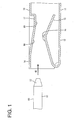
- a terminal fitting according to the first embodiment is composed of at least one pair of female and male terminals 10, 50 connectable with each other. Both terminals 10, 50 are formed particularly by applying bending and the like to an electrically conductive (particularly metal) plate.
- the male terminal 50 includes a tab 51:
- the tab 51 has a substantially flat shape extending in forward and backward directions (longitudinal direction).
- the outer circumferential surface of a leading end side of the tab 51 particularly is cut or hammered to form a tapered guiding surface 52.
- the female terminal 10 includes a tubular main portion 11.
- a wire connection portion (particularly comprising an unillustrated crimping portion) is formed behind the main portion 11.
- the wire connection portion is connectable to an unillustrated wire particularly in that the crimping portion is crimped and connected to an end portion of an unillustrated wire.
- the main portion 11 particularly is in the form of a substantially rectangular tube and includes a base plate 12 continuous with the wire connection portion (particularly the crimping portion), a pair of side plates 13 standing up from the opposite widthwise ends of the base plate 12 and a ceiling plate 14 bridging the upper ends of one and the other side plates 13.
- a resilient contact piece 15 is formed in or at the main portion 11.
- the resilient contact piece 15 particularly is formed to have a substantially mountain shape by folding a part projecting forward from the front end of the base plate 12 backward.
- a top portion of the resilient contact piece 15 particularly is hammered to form a rounded or substantially semispherical contact portion 16 projecting upward or inward.
- Such a resilient contact piece 15 is resiliently deformable in a direction intersecting a tab insertion direction ID (particularly substantially upward and downward) with its part continuous with the front end of the base plate 12 as a supporting point.
- the ceiling plate 14 is formed with a receiving portion 17 at a position substantially facing the resilient contact piece 15 in a resiliently deforming direction of the resilient contact piece 15.
- the receiving portion 17 particularly is formed by hammering a widthwise intermediate or central part of the ceiling plate 14 to project inwardly and/or substantially in the form of a rib extending in forward and backward directions, and/or has a trapezoidal cross section.
- An inner surface of the receiving portion 17 particularly substantially is even and wide in its entirety.
- the inner surface of the receiving portion 17 is formed with a guiding portion 18 inclined to gradually approach the resilient contact piece 15 from its front end toward its back side.
- a starting point of the inclination of the guiding portion 18 particularly is located between the front end of the resilient contact piece 15 and the contact portion 16, and an end point of the inclination of the guiding portion 18 is located between the contact portion 16 and the rear end of the resilient contact piece 15.
- the contact portion 16 is arranged to substantially face an intermediate position of the guiding portion 18.
- the guiding portion 18 is formed with such a length range from a position before a contact position of the tab 51 with the contact portion 16 to the contact position.
- a vertical distance between the end point of the inclination of the guiding portion 18 and the top of the contact portion 16 when the resilient contact piece 15 is in its natural state is set to be smaller than the thickness of the tab 51.
- the inner surface of the receiving portion 17 particularly is formed with a substantially horizontal and/or wide flat surface 19 from the end point of the inclination of the guiding portion 18 to the rear end of the receiving portion 17.
- the terminal fitting according to this-embodiment is structured as above. Next, how to connect the terminal fitting is described.
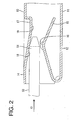
- the male terminal 50 is at least partly accommodated in an unillustrated male connector housing and the female terminal 10 is also at least partly accommodated in an unillustrated female connector housing. Subsequently, the two connector housings are connected with each other. Then, the tab 51 is at least partly inserted into the main portion 11 in the tab insertion direction ID e.g. from front. As shown in FIG. 2 , in an insertion process, the tab 51 comes into contact with the guiding portion 18 before coming into contact with the contact portion 16 and is or may be displaced in a direction intersecting with the tab insertion direction ID or little by little toward the contact portion 16 while substantially sliding on the guiding portion 18.
- the tab 51 comes into contact with the contact portion 16 from above to resiliently deform the resilient contact piece 15 substantially outward or downward. Also during resilient deformation of the resilient contact piece 15, the tab 51 keeps substantially sliding on the guiding portion 18. When a leading end portion of the tab 51 reaches a position to be held in contact with the flat surface 19 as shown in FIG. 3 in this way, the tab 51 is resiliently tightly held between the receiving portion 17 and the resilient contact piece 15, with the result that both female and male terminals 10, 50 are electrically connected.
- the tab 51 is guided by the guiding portion 18 and reaches the position to be held in contact with the contact portion 16 when being at least partly inserted into the main portion 11.
- a sudden increase in insertion resistance can be prevented.
- the contact portion 16 is arranged to substantially face the intermediate position of the guiding portion 18, a guiding function by the guiding portion 18 can be displayed with the tab 51 held in contact with the contact portion 16. Therefore, insertion resistance accompanying the contact of the tab 51 and the contact portion 16 can be gradually increased, wherefore operability upon bringing both female and male terminals 10, 50 into contact is improved.
- the receiving portion 17 can have both a function of holding the tab 51 between the resilient contact piece 15 and itself and a function of guiding the tab 51. As a result, the construction of the main portion 11 can be simplified.
- a tab 51 of a male terminal 50 is to be at least partly inserted into a main portion 11 of a female terminal 10.
- the tab 51 comes substantially into contact with a contact portion 16 of a resilient contact piece 15, whereby both female and male terminals 10, 50 are electrically connected.
- a guiding portion 18 for guiding the tab 51 at least partly inserted into this main portion 11 to a position where the tab 51 comes into contact with the contact portion 16 is formed on an inner surface of the main portion 11.
- the guiding portion 18 is formed from a position before a contact position of the tab 51 with the contact portion 16 to the contact position while being inclined with respect to an inserting direction ID of the tab 51.
- FIGS. 5 and 6 show a second preferred embodiment of the present invention.
- this female terminal 10 a widthwise intermediate or central part of a ceiling plate 14 of a main portion 11 is hammered or deformed to substantially project inward or downward, thereby forming a narrow receiving portion 17A.
- This receiving portion 17A particularly has a substantially V- or U-shaped cross section.
- a top portion of the receiving portion 17A serves as a guiding portion 18A inclined to gradually approach a resilient contact piece 15 from its front end toward its rear end.
- the other construction is substantially similar to or same as that of the first embodiment.
- the tab 51 In the process of inserting a tab 51 into the main portion 11, the tab 51 is guided toward or to a contact position with a contact portion 16 by the guiding portion 18A. When being inserted to a proper depth in the main portion 11, the tab 51 is tightly held between the guiding portion 18A and the contact portion 16 while being supported at two points. In this way, both terminals 10, 50 are electrically connected. According to such a second embodiment, the effects described in the above first embodiment can be enjoyed.
- FIG. 7 shows a third embodiment of the present invention.
- this female terminal 10 opposite widthwise sides of a ceiling plate 14 of a main portion 11 are hammered or deformed to substantially project inward or downward, thereby forming a pair of substantially narrow receiving portions 178.
- the pair of receiving portions 17B overall have a substantially W-shape.
- Each receiving portion 17B has a substantially U-shaped cross section.
- a top or distal portion of each receiving portion 17B serves as a guiding portion 18B inclined to gradually approach a resilient contact piece 15 from its front end toward its rear end.
- the other construction is substantially similar to or same as that of the first embodiment.
- FIG. 8 shows a fourth embodiment of the present invention.
- a receiving portion 17C formed at a ceiling plate 14 of this female terminal 10 is formed with no guiding portion. Specifically, not a guiding portion, but a substantially flat surface 19C is formed at a position of the receiving portion 17C substantially facing a contact portion 16.
- An inclined portion 21 shorter than the guiding portion 18 in forward and backward directions is formed at a front end portion of the receiving portion 17C.
- the other construction of the female terminal 10 is substantially similar to or same as that of the first embodiment.
- an inclined projection 53 is formed on the outer circumferential surface of a leading end side of a tab 51.
- the upper surface of the inclined projection 53 serves as a guiding portion 54 gradually inclined upward or outward from an end point of a guiding surface 52 toward a back side.
- the guiding portion 54 particularly substantially is even and/or wide.
- Such a guiding portion 54 is also formed from a position before a contact position of the tab 51 with a contact portion 16 to the contact position with the contact portion 16.
- the guiding portion 54 slides on the inclined portion 21 of the receiving portion 17C and the tab 51 is displaced toward a resilient contact piece 15. While the guiding portion 18 substantially is sliding on the inclined portion 21 of the receiving portion 17C, the tab 51 comes into contact with the contact portion 16 from above to resiliently deform the resilient contact piece 15 in a direction intersecting with the tab inserting direction ID or substantially downward.
- the tab 51 is resiliently tightly held between the flat surface 19C of the receiving portion 17C and the contact portion 16, whereby both terminals 10, 50 are electrically connected.
- the guiding portion can be deleted from the female terminal 10 and the construction of the female terminal 10 can be simplified since the guiding portion 54 is formed on the outer circumferential surface of the tab 51.
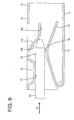
- FIG. 9 shows a fifth preferred embodiment of the present invention.
- a part of a ceiling plate 14 is cut and bent into a main portion 11, thereby forming a receiving portion 17D.
- An inner surface of the receiving portion 17D is formed with a guiding portion 18D gradually inclined toward a resilient contact piece 15 from its front end toward its rear side and a substantially horizontal flat surface 19D from an end point of the inclination of the guiding portion 18D to the rear end of the receiving portion 17D.
- a part of the ceiling plate 14 before the receiving portion 17 is hammered or deformed to substantially project inward or downward, thereby forming a front receiving portion 22.
- a substantially horizontal and/or wide supporting surface 23 particularly is formed on an inner surface of the front receiving portion 22.
- the other construction is substantially similar to or same as that of the first embodiment.
- the upper surface of the tab 51 slides on the supporting surface 23 of the front receiving portion 22 and the leading end of the tab 51 slides on the guiding portion 18D, whereby the tab 51 is substantially displaced toward the contact portion 16. While the leading end of the tab 51 substantially is sliding on the guiding portion 18D, the resilient contact piece 15 is resiliently pushed down by the tab 51 to increase insertion resistance gradually or little by little.
- the tab 51 is resiliently tightly held between the flat surface 19D of the receiving portion 17D and the contact portion 16, whereby both terminals 10, 50 are electrically connected.
- the guiding portion 18D is formed on the inner surface of the receiving portion 17D particularly formed by cutting the part of the ceiling plate 14 of the main portion 11 and bending this cut part toward the contact portion 16, a degree of freedom in the form of the guiding portion 18D can be increased as compared with the case where the guiding portion is formed by hammering the ceiling plate 14 to project toward the contact portion 16.
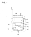
- FIGS. 10 and 11 show a sixth preferred embodiment of the present invention. This differs from the terminal fitting of the first embodiment in its basic structure.
- a main portion 11 E of a female terminal 10E has an upper portion (preferably substantially an upper half) thereof closed by a closing wall 24 hanging down or inwardly or projecting from the front end of a ceiling plate 14E, and an insertion opening 25 for a tab 51 E is formed in a lower portion (preferably substantially in a lower half).
- At least one stabilizer 25 is formed to stand up from the upper end of a side plate 13E particularly by cutting and bending a part of the ceiling plate 14E.
- a resiliently deformable resilient contact piece 15E is formed in or at or on the main portion 11 E.
- the resilient contact piece 15E particularly is formed by folding a part extending backward from the rear end of the ceiling plate 14E forward and closely bending the forward extending part at a position facing the insertion opening 25 such that the leading end thereof extends up to the inner surface of the ceiling plate 14E.
- a contact portion 16E is formed to project at a bottom end of a closely bent part of the resilient contact piece 15E.
- Substantially opposite widthwise end portions of a bottom plate 12E are hammered or deformed to project inward or upward, thereby forming a pair of receiving portions 17E.
- First guiding portions 18E inclined to gradually approach the resilient contact piece 15E from the front end of the bottom plate 12E toward a rear side thereof are formed on inner surfaces of the respective receiving portions 17E.
- the respective receiving portions 17E are arranged at the substantially opposite sides of the contact portion 16E with respect to a width direction as shown in FIG. 11 .
- the outer circumferential surface of the tab 51 E are cut at substantially opposite widthwise sides thereof, thereby forming a pair of second guiding portions 54E gradually sloped downward from the leading ends thereof toward rear sides thereof.
- the respective second guiding portions 54E are in such a positional relationship as to at least partly overlap a guiding surface 52E formed on the outer circumferential surface of a leading end side of the tab 51 E.
- the respective second guiding portions 54E slide on the corresponding first guiding portions 18E to gradually displace the tab 51 E substantially toward the contact portion 16E.
- the resilient contact piece 15E is resiliently deformed outward or upward.
- a sliding contact state of the first and second guiding portions 18E, 54 is maintained to increase insertion resistance of the tab 51 E gradually or little by little.
- a contact load accompanying the contact of the tab 51 E and the contact portion 16E can be increased by a smaller degree, wherefore operability is further improved.
Landscapes
- Details Of Connecting Devices For Male And Female Coupling (AREA)
- Connector Housings Or Holding Contact Members (AREA)
Applications Claiming Priority (2)
| Application Number | Priority Date | Filing Date | Title |
|---|---|---|---|
| JP2009274696A JP5375564B2 (ja) | 2009-12-02 | 2009-12-02 | 端子金具 |
| EP10014470A EP2330691A1 (de) | 2009-12-02 | 2010-11-10 | Anschlussstück, Buchsenanschlussstück und Verfahren zur Herstellung eines elektrischen Kontakts eines Anschlussstücks |
Related Parent Applications (2)
| Application Number | Title | Priority Date | Filing Date |
|---|---|---|---|
| EP10014470.8 Division | 2010-11-10 | ||
| EP10014470A Division EP2330691A1 (de) | 2009-12-02 | 2010-11-10 | Anschlussstück, Buchsenanschlussstück und Verfahren zur Herstellung eines elektrischen Kontakts eines Anschlussstücks |
Publications (2)
| Publication Number | Publication Date |
|---|---|
| EP2432079A1 true EP2432079A1 (de) | 2012-03-21 |
| EP2432079B1 EP2432079B1 (de) | 2014-12-24 |
Family
ID=43478117
Family Applications (2)
| Application Number | Title | Priority Date | Filing Date |
|---|---|---|---|
| EP10014470A Withdrawn EP2330691A1 (de) | 2009-12-02 | 2010-11-10 | Anschlussstück, Buchsenanschlussstück und Verfahren zur Herstellung eines elektrischen Kontakts eines Anschlussstücks |
| EP11009725.0A Not-in-force EP2432079B1 (de) | 2009-12-02 | 2010-11-10 | Anschlussstück, Buchsenanschlussstück und Verfahren zur Herstellung eines elektrischen Kontakts eines Anschlussstücks |
Family Applications Before (1)
| Application Number | Title | Priority Date | Filing Date |
|---|---|---|---|
| EP10014470A Withdrawn EP2330691A1 (de) | 2009-12-02 | 2010-11-10 | Anschlussstück, Buchsenanschlussstück und Verfahren zur Herstellung eines elektrischen Kontakts eines Anschlussstücks |
Country Status (4)
| Country | Link |
|---|---|
| US (2) | US8152576B2 (de) |
| EP (2) | EP2330691A1 (de) |
| JP (1) | JP5375564B2 (de) |
| CN (1) | CN102148449B (de) |
Families Citing this family (20)
| Publication number | Priority date | Publication date | Assignee | Title |
|---|---|---|---|---|
| CN102790308B (zh) * | 2011-05-20 | 2015-08-12 | 泰科电子(上海)有限公司 | 电连接器端子 |
| CN102354831B (zh) * | 2011-08-15 | 2013-10-16 | 浙江正泰建筑电器有限公司 | 无螺纹接线端子装置 |
| JP2013098088A (ja) * | 2011-11-02 | 2013-05-20 | Sumitomo Wiring Syst Ltd | 雌型端子金具 |
| JP5829937B2 (ja) | 2012-02-15 | 2015-12-09 | 矢崎総業株式会社 | 端子接続構造 |
| JP5247902B1 (ja) * | 2012-02-24 | 2013-07-24 | 日本航空電子工業株式会社 | 電気コネクタ |
| JP2014049375A (ja) * | 2012-09-03 | 2014-03-17 | Yazaki Corp | 接続端子 |
| CN202772303U (zh) * | 2012-09-04 | 2013-03-06 | 泰科电子(上海)有限公司 | 电连接器和电连接器组件 |
| US9118130B1 (en) * | 2014-02-06 | 2015-08-25 | Delphi Technologies, Inc. | Low insertion force terminal |
| WO2015125682A1 (ja) * | 2014-02-18 | 2015-08-27 | 矢崎総業株式会社 | 接続端子 |
| JP5831611B1 (ja) * | 2014-09-19 | 2015-12-09 | 第一精工株式会社 | コネクタ端子の接続構造 |
| US20160344127A1 (en) * | 2015-05-20 | 2016-11-24 | Delphi Technologies, Inc. | Electroconductive material with an undulating surface, an electrical terminal formed of said material, and a method of producing said material |
| JP6154430B2 (ja) * | 2015-06-02 | 2017-06-28 | 矢崎総業株式会社 | 雌端子金具及びそれを備えたコネクタ |
| US10090608B2 (en) | 2016-09-29 | 2018-10-02 | Delphi Technologies, Inc. | Electrical connection system having a terminal with contact ridges |
| JP6807024B2 (ja) * | 2017-04-14 | 2021-01-06 | 株式会社オートネットワーク技術研究所 | 雌端子 |
| JP6588943B2 (ja) | 2017-06-20 | 2019-10-09 | 矢崎総業株式会社 | 端子接続構造 |
| JP6576979B2 (ja) * | 2017-07-20 | 2019-09-18 | 矢崎総業株式会社 | 端子接続構造 |
| JP2019029216A (ja) * | 2017-07-31 | 2019-02-21 | 住友電装株式会社 | 雌端子 |
| JP6802227B2 (ja) * | 2018-09-14 | 2020-12-16 | 矢崎総業株式会社 | 接続端子 |
| JP7396203B2 (ja) * | 2020-06-01 | 2023-12-12 | 株式会社オートネットワーク技術研究所 | ヒューズ内蔵コネクタ、およびコネクタ構造体 |
| JP7168626B2 (ja) * | 2020-10-23 | 2022-11-09 | 矢崎総業株式会社 | 接続端子 |
Citations (6)
| Publication number | Priority date | Publication date | Assignee | Title |
|---|---|---|---|---|
| EP0657961A2 (de) * | 1993-12-08 | 1995-06-14 | Sumitomo Wiring Systems, Ltd. | Steckerelemente und deren Herstellungsverfahren |
| EP0693798A1 (de) * | 1994-07-20 | 1996-01-24 | Sumitomo Wiring Systems, Ltd. | Metalleinheit für Steckerkontakte |
| EP1184941A1 (de) * | 2000-08-28 | 2002-03-06 | Sumitomo Wiring Systems, Ltd. | Kontaktbüchsenarmatur |
| JP2003346958A (ja) | 2002-05-29 | 2003-12-05 | Sumitomo Wiring Syst Ltd | 雌端子金具 |
| US20060172618A1 (en) * | 2005-01-28 | 2006-08-03 | Sumitomo Wiring Systems, Ltd. | Female terminal fitting |
| EP1919036A2 (de) * | 2006-11-01 | 2008-05-07 | Sumitomo Wiring Systems, Ltd. | Anschlussstück und Anschlussverfahren |
Family Cites Families (19)
| Publication number | Priority date | Publication date | Assignee | Title |
|---|---|---|---|---|
| JP2772325B2 (ja) * | 1992-03-02 | 1998-07-02 | 矢崎総業株式会社 | 雄端子結合用中継端子 |
| JPH0587837U (ja) * | 1992-04-23 | 1993-11-26 | 矢崎総業株式会社 | コネクタの雄端子構造 |
| FR2711853B1 (fr) * | 1993-10-26 | 1995-12-01 | Cinch Connecteurs Sa | Organe de contact électrique femelle. |
| US5593328A (en) * | 1993-11-04 | 1997-01-14 | Sumitomo Wiring Systems, Ltd. | Female terminal fitting for connector |
| JP3082613B2 (ja) * | 1995-02-22 | 2000-08-28 | 住友電装株式会社 | 雌端子金具 |
| JPH0935796A (ja) * | 1995-07-24 | 1997-02-07 | Yazaki Corp | 雌端子 |
| JP3807646B2 (ja) * | 1997-10-31 | 2006-08-09 | 矢崎総業株式会社 | 端子のへたり防止構造 |
| JPH11214058A (ja) * | 1998-01-29 | 1999-08-06 | Yazaki Corp | 雌端子 |
| JP3645449B2 (ja) * | 1999-06-17 | 2005-05-11 | 矢崎総業株式会社 | 端子構造 |
| JP3686551B2 (ja) * | 1999-06-17 | 2005-08-24 | 矢崎総業株式会社 | 端子金具 |
| JP2002015803A (ja) * | 2000-06-30 | 2002-01-18 | Sumitomo Wiring Syst Ltd | 端子金具の接続構造 |
| JP4379231B2 (ja) * | 2004-07-07 | 2009-12-09 | 住友電装株式会社 | 雌端子金具 |
| JP2006216321A (ja) * | 2005-02-02 | 2006-08-17 | Sumitomo Wiring Syst Ltd | 端子金具 |
| US7387550B2 (en) * | 2005-07-21 | 2008-06-17 | Tyco Electronics Corporation | Dual beam receptacle contact |
| JP2007149504A (ja) * | 2005-11-28 | 2007-06-14 | Yazaki Corp | 雌端子及びコネクタ |
| DE102006009074B4 (de) * | 2006-02-28 | 2016-02-25 | Robert Bosch Gmbh | Elektrischer Steckverbinder mit vorgespannter Kontaktlamelle |
| JP4858293B2 (ja) * | 2007-05-08 | 2012-01-18 | 住友電装株式会社 | 雌端子金具 |
| JP2008293722A (ja) * | 2007-05-23 | 2008-12-04 | Sumitomo Wiring Syst Ltd | コネクタ |
| JP5179926B2 (ja) * | 2008-04-07 | 2013-04-10 | 日本圧着端子製造株式会社 | 雄端子及びこれを有するコネクタ |
-
2009
- 2009-12-02 JP JP2009274696A patent/JP5375564B2/ja not_active Expired - Fee Related
-
2010
- 2010-11-10 EP EP10014470A patent/EP2330691A1/de not_active Withdrawn
- 2010-11-10 EP EP11009725.0A patent/EP2432079B1/de not_active Not-in-force
- 2010-11-24 US US12/954,178 patent/US8152576B2/en not_active Expired - Fee Related
- 2010-11-25 CN CN2010105634289A patent/CN102148449B/zh not_active Expired - Fee Related
-
2012
- 2012-01-11 US US13/347,939 patent/US8206187B2/en not_active Expired - Fee Related
Patent Citations (6)
| Publication number | Priority date | Publication date | Assignee | Title |
|---|---|---|---|---|
| EP0657961A2 (de) * | 1993-12-08 | 1995-06-14 | Sumitomo Wiring Systems, Ltd. | Steckerelemente und deren Herstellungsverfahren |
| EP0693798A1 (de) * | 1994-07-20 | 1996-01-24 | Sumitomo Wiring Systems, Ltd. | Metalleinheit für Steckerkontakte |
| EP1184941A1 (de) * | 2000-08-28 | 2002-03-06 | Sumitomo Wiring Systems, Ltd. | Kontaktbüchsenarmatur |
| JP2003346958A (ja) | 2002-05-29 | 2003-12-05 | Sumitomo Wiring Syst Ltd | 雌端子金具 |
| US20060172618A1 (en) * | 2005-01-28 | 2006-08-03 | Sumitomo Wiring Systems, Ltd. | Female terminal fitting |
| EP1919036A2 (de) * | 2006-11-01 | 2008-05-07 | Sumitomo Wiring Systems, Ltd. | Anschlussstück und Anschlussverfahren |
Also Published As
| Publication number | Publication date |
|---|---|
| EP2330691A1 (de) | 2011-06-08 |
| CN102148449B (zh) | 2013-09-18 |
| US20110130051A1 (en) | 2011-06-02 |
| US8206187B2 (en) | 2012-06-26 |
| JP2011119109A (ja) | 2011-06-16 |
| CN102148449A (zh) | 2011-08-10 |
| US8152576B2 (en) | 2012-04-10 |
| JP5375564B2 (ja) | 2013-12-25 |
| US20120108114A1 (en) | 2012-05-03 |
| EP2432079B1 (de) | 2014-12-24 |
Similar Documents
| Publication | Publication Date | Title |
|---|---|---|
| EP2432079A1 (de) | Anschlussstück, Buchsenanschlussstück und Verfahren zur Herstellung eines elektrischen Kontakts eines Anschlussstücks | |
| EP1990866B1 (de) | Buchsenkontakt | |
| EP2852004B1 (de) | Anschlussstück | |
| CN100566038C (zh) | 阴性端子接头,用于数个端子接头的坯料以及形成阴性端子接头的方法 | |
| US20050032440A1 (en) | Female terminal fitting and method of assembling such terminal fitting | |
| EP2166624A1 (de) | Elastischer Stecker, wasserdichter Stecker und Anordnungsverfahren dafür | |
| EP2309603A1 (de) | Kontaktbuchsenarmatur und Verfahren zum Anschliessen desselben | |
| EP2244334A1 (de) | Anschlussstück und Verfahren zu dessen Herstellung | |
| EP2086062A1 (de) | Anschlüsse, Anschlussverbindungsstruktur und Verbindungsverfahren | |
| US8523619B2 (en) | Terminal fitting | |
| EP2157669A1 (de) | Steckverbinder und Montageverfahren dafür | |
| US8454394B2 (en) | Terminal fitting having an auxilary resilient piece | |
| US10270197B2 (en) | Female terminal having a resiliently displaceable contact piece folded rearward from a front end of a step | |
| CN101005171B (zh) | 端子接头及设置有该端子接头的连接器 | |
| EP2544309B1 (de) | Anschlussstück und Verfahren für dessen Herstellung | |
| JP6143194B2 (ja) | 雄端子金具 | |
| EP2164132A1 (de) | Anschlussstück, Steckverbinder und Montageverfahren dafür | |
| CN103022779B (zh) | 连接器 | |
| US10985486B2 (en) | Female terminal | |
| JP3122589U (ja) | 端子金具 | |
| EP2187478A1 (de) | Anschlussstück, Drahtverbindungsstruktur und Verbindungsverfahren | |
| JP2008192419A (ja) | 端子金具およびコネクタ | |
| JP2002042949A (ja) | 端子金具 | |
| JP2010140874A (ja) | オス端子の構造 | |
| JP2011159640A (ja) | 端子金具およびコネクタ |
Legal Events
| Date | Code | Title | Description |
|---|---|---|---|
| PUAI | Public reference made under article 153(3) epc to a published international application that has entered the european phase |
Free format text: ORIGINAL CODE: 0009012 |
|
| AC | Divisional application: reference to earlier application |
Ref document number: 2330691 Country of ref document: EP Kind code of ref document: P |
|
| AK | Designated contracting states |
Kind code of ref document: A1 Designated state(s): AL AT BE BG CH CY CZ DE DK EE ES FI FR GB GR HR HU IE IS IT LI LT LU LV MC MK MT NL NO PL PT RO RS SE SI SK SM TR |
|
| AX | Request for extension of the european patent |
Extension state: BA ME |
|
| 17P | Request for examination filed |
Effective date: 20120524 |
|
| GRAP | Despatch of communication of intention to grant a patent |
Free format text: ORIGINAL CODE: EPIDOSNIGR1 |
|
| RIC1 | Information provided on ipc code assigned before grant |
Ipc: H01R 13/05 20060101ALI20140730BHEP Ipc: H01R 13/11 20060101AFI20140730BHEP |
|
| INTG | Intention to grant announced |
Effective date: 20140818 |
|
| GRAS | Grant fee paid |
Free format text: ORIGINAL CODE: EPIDOSNIGR3 |
|
| GRAA | (expected) grant |
Free format text: ORIGINAL CODE: 0009210 |
|
| AC | Divisional application: reference to earlier application |
Ref document number: 2330691 Country of ref document: EP Kind code of ref document: P |
|
| AK | Designated contracting states |
Kind code of ref document: B1 Designated state(s): AL AT BE BG CH CY CZ DE DK EE ES FI FR GB GR HR HU IE IS IT LI LT LU LV MC MK MT NL NO PL PT RO RS SE SI SK SM TR |
|
| REG | Reference to a national code |
Ref country code: GB Ref legal event code: FG4D |
|
| REG | Reference to a national code |
Ref country code: CH Ref legal event code: EP |
|
| REG | Reference to a national code |
Ref country code: IE Ref legal event code: FG4D |
|
| REG | Reference to a national code |
Ref country code: AT Ref legal event code: REF Ref document number: 703555 Country of ref document: AT Kind code of ref document: T Effective date: 20150115 |
|
| REG | Reference to a national code |
Ref country code: DE Ref legal event code: R096 Ref document number: 602010021327 Country of ref document: DE Effective date: 20150219 |
|
| REG | Reference to a national code |
Ref country code: NL Ref legal event code: VDEP Effective date: 20141224 |
|
| PG25 | Lapsed in a contracting state [announced via postgrant information from national office to epo] |
Ref country code: LT Free format text: LAPSE BECAUSE OF FAILURE TO SUBMIT A TRANSLATION OF THE DESCRIPTION OR TO PAY THE FEE WITHIN THE PRESCRIBED TIME-LIMIT Effective date: 20141224 Ref country code: FI Free format text: LAPSE BECAUSE OF FAILURE TO SUBMIT A TRANSLATION OF THE DESCRIPTION OR TO PAY THE FEE WITHIN THE PRESCRIBED TIME-LIMIT Effective date: 20141224 Ref country code: NO Free format text: LAPSE BECAUSE OF FAILURE TO SUBMIT A TRANSLATION OF THE DESCRIPTION OR TO PAY THE FEE WITHIN THE PRESCRIBED TIME-LIMIT Effective date: 20150324 |
|
| REG | Reference to a national code |
Ref country code: LT Ref legal event code: MG4D |
|
| PG25 | Lapsed in a contracting state [announced via postgrant information from national office to epo] |
Ref country code: GR Free format text: LAPSE BECAUSE OF FAILURE TO SUBMIT A TRANSLATION OF THE DESCRIPTION OR TO PAY THE FEE WITHIN THE PRESCRIBED TIME-LIMIT Effective date: 20150325 Ref country code: SE Free format text: LAPSE BECAUSE OF FAILURE TO SUBMIT A TRANSLATION OF THE DESCRIPTION OR TO PAY THE FEE WITHIN THE PRESCRIBED TIME-LIMIT Effective date: 20141224 Ref country code: RS Free format text: LAPSE BECAUSE OF FAILURE TO SUBMIT A TRANSLATION OF THE DESCRIPTION OR TO PAY THE FEE WITHIN THE PRESCRIBED TIME-LIMIT Effective date: 20141224 Ref country code: HR Free format text: LAPSE BECAUSE OF FAILURE TO SUBMIT A TRANSLATION OF THE DESCRIPTION OR TO PAY THE FEE WITHIN THE PRESCRIBED TIME-LIMIT Effective date: 20141224 Ref country code: LV Free format text: LAPSE BECAUSE OF FAILURE TO SUBMIT A TRANSLATION OF THE DESCRIPTION OR TO PAY THE FEE WITHIN THE PRESCRIBED TIME-LIMIT Effective date: 20141224 |
|
| REG | Reference to a national code |
Ref country code: AT Ref legal event code: MK05 Ref document number: 703555 Country of ref document: AT Kind code of ref document: T Effective date: 20141224 |
|
| PG25 | Lapsed in a contracting state [announced via postgrant information from national office to epo] |
Ref country code: NL Free format text: LAPSE BECAUSE OF FAILURE TO SUBMIT A TRANSLATION OF THE DESCRIPTION OR TO PAY THE FEE WITHIN THE PRESCRIBED TIME-LIMIT Effective date: 20141224 |
|
| PG25 | Lapsed in a contracting state [announced via postgrant information from national office to epo] |
Ref country code: ES Free format text: LAPSE BECAUSE OF FAILURE TO SUBMIT A TRANSLATION OF THE DESCRIPTION OR TO PAY THE FEE WITHIN THE PRESCRIBED TIME-LIMIT Effective date: 20141224 Ref country code: CZ Free format text: LAPSE BECAUSE OF FAILURE TO SUBMIT A TRANSLATION OF THE DESCRIPTION OR TO PAY THE FEE WITHIN THE PRESCRIBED TIME-LIMIT Effective date: 20141224 Ref country code: RO Free format text: LAPSE BECAUSE OF FAILURE TO SUBMIT A TRANSLATION OF THE DESCRIPTION OR TO PAY THE FEE WITHIN THE PRESCRIBED TIME-LIMIT Effective date: 20141224 Ref country code: SK Free format text: LAPSE BECAUSE OF FAILURE TO SUBMIT A TRANSLATION OF THE DESCRIPTION OR TO PAY THE FEE WITHIN THE PRESCRIBED TIME-LIMIT Effective date: 20141224 Ref country code: EE Free format text: LAPSE BECAUSE OF FAILURE TO SUBMIT A TRANSLATION OF THE DESCRIPTION OR TO PAY THE FEE WITHIN THE PRESCRIBED TIME-LIMIT Effective date: 20141224 |
|
| PG25 | Lapsed in a contracting state [announced via postgrant information from national office to epo] |
Ref country code: IS Free format text: LAPSE BECAUSE OF FAILURE TO SUBMIT A TRANSLATION OF THE DESCRIPTION OR TO PAY THE FEE WITHIN THE PRESCRIBED TIME-LIMIT Effective date: 20150424 Ref country code: PL Free format text: LAPSE BECAUSE OF FAILURE TO SUBMIT A TRANSLATION OF THE DESCRIPTION OR TO PAY THE FEE WITHIN THE PRESCRIBED TIME-LIMIT Effective date: 20141224 Ref country code: AT Free format text: LAPSE BECAUSE OF FAILURE TO SUBMIT A TRANSLATION OF THE DESCRIPTION OR TO PAY THE FEE WITHIN THE PRESCRIBED TIME-LIMIT Effective date: 20141224 |
|
| REG | Reference to a national code |
Ref country code: DE Ref legal event code: R097 Ref document number: 602010021327 Country of ref document: DE |
|
| PG25 | Lapsed in a contracting state [announced via postgrant information from national office to epo] |
Ref country code: DK Free format text: LAPSE BECAUSE OF FAILURE TO SUBMIT A TRANSLATION OF THE DESCRIPTION OR TO PAY THE FEE WITHIN THE PRESCRIBED TIME-LIMIT Effective date: 20141224 |
|
| PLBE | No opposition filed within time limit |
Free format text: ORIGINAL CODE: 0009261 |
|
| STAA | Information on the status of an ep patent application or granted ep patent |
Free format text: STATUS: NO OPPOSITION FILED WITHIN TIME LIMIT |
|
| 26N | No opposition filed |
Effective date: 20150925 |
|
| PG25 | Lapsed in a contracting state [announced via postgrant information from national office to epo] |
Ref country code: SI Free format text: LAPSE BECAUSE OF FAILURE TO SUBMIT A TRANSLATION OF THE DESCRIPTION OR TO PAY THE FEE WITHIN THE PRESCRIBED TIME-LIMIT Effective date: 20141224 |
|
| PG25 | Lapsed in a contracting state [announced via postgrant information from national office to epo] |
Ref country code: BE Free format text: LAPSE BECAUSE OF FAILURE TO SUBMIT A TRANSLATION OF THE DESCRIPTION OR TO PAY THE FEE WITHIN THE PRESCRIBED TIME-LIMIT Effective date: 20141224 |
|
| REG | Reference to a national code |
Ref country code: DE Ref legal event code: R119 Ref document number: 602010021327 Country of ref document: DE |
|
| PG25 | Lapsed in a contracting state [announced via postgrant information from national office to epo] |
Ref country code: LU Free format text: LAPSE BECAUSE OF FAILURE TO SUBMIT A TRANSLATION OF THE DESCRIPTION OR TO PAY THE FEE WITHIN THE PRESCRIBED TIME-LIMIT Effective date: 20151110 Ref country code: MC Free format text: LAPSE BECAUSE OF FAILURE TO SUBMIT A TRANSLATION OF THE DESCRIPTION OR TO PAY THE FEE WITHIN THE PRESCRIBED TIME-LIMIT Effective date: 20141224 |
|
| REG | Reference to a national code |
Ref country code: CH Ref legal event code: PL |
|
| GBPC | Gb: european patent ceased through non-payment of renewal fee |
Effective date: 20151110 |
|
| PG25 | Lapsed in a contracting state [announced via postgrant information from national office to epo] |
Ref country code: CH Free format text: LAPSE BECAUSE OF NON-PAYMENT OF DUE FEES Effective date: 20151130 Ref country code: LI Free format text: LAPSE BECAUSE OF NON-PAYMENT OF DUE FEES Effective date: 20151130 |
|
| REG | Reference to a national code |
Ref country code: IE Ref legal event code: MM4A |
|
| REG | Reference to a national code |
Ref country code: FR Ref legal event code: ST Effective date: 20160729 |
|
| PG25 | Lapsed in a contracting state [announced via postgrant information from national office to epo] |
Ref country code: IE Free format text: LAPSE BECAUSE OF NON-PAYMENT OF DUE FEES Effective date: 20151110 Ref country code: DE Free format text: LAPSE BECAUSE OF NON-PAYMENT OF DUE FEES Effective date: 20160601 Ref country code: GB Free format text: LAPSE BECAUSE OF NON-PAYMENT OF DUE FEES Effective date: 20151110 |
|
| PG25 | Lapsed in a contracting state [announced via postgrant information from national office to epo] |
Ref country code: FR Free format text: LAPSE BECAUSE OF NON-PAYMENT OF DUE FEES Effective date: 20151130 |
|
| PG25 | Lapsed in a contracting state [announced via postgrant information from national office to epo] |
Ref country code: IT Free format text: LAPSE BECAUSE OF NON-PAYMENT OF DUE FEES Effective date: 20151110 |
|
| PG25 | Lapsed in a contracting state [announced via postgrant information from national office to epo] |
Ref country code: BG Free format text: LAPSE BECAUSE OF FAILURE TO SUBMIT A TRANSLATION OF THE DESCRIPTION OR TO PAY THE FEE WITHIN THE PRESCRIBED TIME-LIMIT Effective date: 20141224 Ref country code: SM Free format text: LAPSE BECAUSE OF FAILURE TO SUBMIT A TRANSLATION OF THE DESCRIPTION OR TO PAY THE FEE WITHIN THE PRESCRIBED TIME-LIMIT Effective date: 20141224 Ref country code: HU Free format text: LAPSE BECAUSE OF FAILURE TO SUBMIT A TRANSLATION OF THE DESCRIPTION OR TO PAY THE FEE WITHIN THE PRESCRIBED TIME-LIMIT; INVALID AB INITIO Effective date: 20101110 |
|
| PG25 | Lapsed in a contracting state [announced via postgrant information from national office to epo] |
Ref country code: CY Free format text: LAPSE BECAUSE OF FAILURE TO SUBMIT A TRANSLATION OF THE DESCRIPTION OR TO PAY THE FEE WITHIN THE PRESCRIBED TIME-LIMIT Effective date: 20141224 |
|
| PG25 | Lapsed in a contracting state [announced via postgrant information from national office to epo] |
Ref country code: TR Free format text: LAPSE BECAUSE OF FAILURE TO SUBMIT A TRANSLATION OF THE DESCRIPTION OR TO PAY THE FEE WITHIN THE PRESCRIBED TIME-LIMIT Effective date: 20141224 Ref country code: MT Free format text: LAPSE BECAUSE OF FAILURE TO SUBMIT A TRANSLATION OF THE DESCRIPTION OR TO PAY THE FEE WITHIN THE PRESCRIBED TIME-LIMIT Effective date: 20141224 |
|
| PG25 | Lapsed in a contracting state [announced via postgrant information from national office to epo] |
Ref country code: MK Free format text: LAPSE BECAUSE OF FAILURE TO SUBMIT A TRANSLATION OF THE DESCRIPTION OR TO PAY THE FEE WITHIN THE PRESCRIBED TIME-LIMIT Effective date: 20141224 |
|
| PG25 | Lapsed in a contracting state [announced via postgrant information from national office to epo] |
Ref country code: PT Free format text: LAPSE BECAUSE OF FAILURE TO SUBMIT A TRANSLATION OF THE DESCRIPTION OR TO PAY THE FEE WITHIN THE PRESCRIBED TIME-LIMIT Effective date: 20141224 |
|
| PG25 | Lapsed in a contracting state [announced via postgrant information from national office to epo] |
Ref country code: AL Free format text: LAPSE BECAUSE OF FAILURE TO SUBMIT A TRANSLATION OF THE DESCRIPTION OR TO PAY THE FEE WITHIN THE PRESCRIBED TIME-LIMIT Effective date: 20141224 |