EP2432089A2 - Combinaison d'appareils pour la protection contre les surtensions - Google Patents
Combinaison d'appareils pour la protection contre les surtensions Download PDFInfo
- Publication number
- EP2432089A2 EP2432089A2 EP11006746A EP11006746A EP2432089A2 EP 2432089 A2 EP2432089 A2 EP 2432089A2 EP 11006746 A EP11006746 A EP 11006746A EP 11006746 A EP11006746 A EP 11006746A EP 2432089 A2 EP2432089 A2 EP 2432089A2
- Authority
- EP
- European Patent Office
- Prior art keywords
- plug
- module
- device combination
- spring
- contact
- Prior art date
- Legal status (The legal status is an assumption and is not a legal conclusion. Google has not performed a legal analysis and makes no representation as to the accuracy of the status listed.)
- Granted
Links
Images


Classifications
-
- H—ELECTRICITY
- H01—ELECTRIC ELEMENTS
- H01T—SPARK GAPS; OVERVOLTAGE ARRESTERS USING SPARK GAPS; SPARKING PLUGS; CORONA DEVICES; GENERATING IONS TO BE INTRODUCED INTO NON-ENCLOSED GASES
- H01T4/00—Overvoltage arresters using spark gaps
- H01T4/06—Mounting arrangements for a plurality of overvoltage arresters
-
- H—ELECTRICITY
- H01—ELECTRIC ELEMENTS
- H01R—ELECTRICALLY-CONDUCTIVE CONNECTIONS; STRUCTURAL ASSOCIATIONS OF A PLURALITY OF MUTUALLY-INSULATED ELECTRICAL CONNECTING ELEMENTS; COUPLING DEVICES; CURRENT COLLECTORS
- H01R13/00—Details of coupling devices of the kinds covered by groups H01R12/70 or H01R24/00 - H01R33/00
- H01R13/62—Means for facilitating engagement or disengagement of coupling parts or for holding them in engagement
- H01R13/629—Additional means for facilitating engagement or disengagement of coupling parts, e.g. aligning or guiding means, levers, gas pressure electrical locking indicators, manufacturing tolerances
- H01R13/633—Additional means for facilitating engagement or disengagement of coupling parts, e.g. aligning or guiding means, levers, gas pressure electrical locking indicators, manufacturing tolerances for disengagement only
- H01R13/635—Additional means for facilitating engagement or disengagement of coupling parts, e.g. aligning or guiding means, levers, gas pressure electrical locking indicators, manufacturing tolerances for disengagement only by mechanical pressure, e.g. spring force
-
- H—ELECTRICITY
- H01—ELECTRIC ELEMENTS
- H01R—ELECTRICALLY-CONDUCTIVE CONNECTIONS; STRUCTURAL ASSOCIATIONS OF A PLURALITY OF MUTUALLY-INSULATED ELECTRICAL CONNECTING ELEMENTS; COUPLING DEVICES; CURRENT COLLECTORS
- H01R9/00—Structural associations of a plurality of mutually-insulated electrical connecting elements, e.g. terminal strips or terminal blocks; Terminals or binding posts mounted upon a base or in a case; Bases therefor
- H01R9/22—Bases, e.g. strip, block, panel
- H01R9/24—Terminal blocks
- H01R9/2425—Structural association with built-in components
- H01R9/2441—Structural association with built-in components with built-in overvoltage protection
Definitions
- the invention relates to a device combination for protection against overvoltage with a preferably U-shaped lower part and a plug-in with this overvoltage protection element having plug-in module, acting between plug-in module and lower part holding means or latching means are provided, which engage in the inserted position of the parts and the detachable by manipulation and / or be unlocked to remove the plug-in module.
- Such device combinations are known in the art. It is for this purpose, for example, on the DE 2006 033 274 A 1 , the DE 10 2008 021 210 A 1 , the DE 10 2008 017 423 A1 directed. Similar embodiments are from the DE 36 39 533 A 1 known.
- plug-in module with the lower part over non-positive elements is connected, for example by spring pressure of contacts that communicate with each other in the inserted position.
- plug-in module is connected to the lower part by latching means which engage in one another in the inserted position of the parts and which can be released or unlocked by appropriate manipulations.
- plug-in module can be connected to the lower part by form-fitting means, so that a non-detachable connection is achieved in the inserted position by means of positive locking. By appropriate manipulation of the positive connection can be canceled, so that then the plug-in module can be removed.
- plug-in module to be replaced or removed for maintenance purposes, so a costly manipulation is required because it is relatively difficult to solve the parts in the inserted position of the lower part. This is particularly difficult because often several plug-in modules are arranged side by side and locked in the corresponding U-shaped lower part.
- the present invention seeks to provide a device combination generic type, in which the removal of the in Plug-in located plug-in modules is facilitated and in which preferably no additional components for easier removal are necessary.
- the invention proposes that a force acting between the lower part and plug-in module spring element is provided which is biased plugged plug-in module and displaced with dissolved or entrastetem holding means or latching means the plug-in module against plug-in direction in a removal position.
- the plug-in module located in the inserted position can be relatively easily solved by the lower part, for example by the holding means or the locking means are released or unlocked.
- This manipulation is sufficient to achieve that the plug-in module is at least partially pushed out of the lower part in the opposite direction by the spring element, so that it can be grasped by the user in a simple manner by hand and removed from the lower part.
- At least one coil spring is arranged as a spring element.
- Such a coil spring can be relatively easy in the space between the base and plug-in module can be arranged, in addition, the spring force of the coil spring can be adjusted by appropriate dimensioning in a simple manner the intended purpose.
- a leaf spring as a spring element also allows for a corresponding shape design of the leaf spring, the desired function, whereby the spring force can be adjusted by appropriate dimensioning and shaping of the intended use even with a leaf spring.
- the spring element is held captive on the lower part.
- the spring element remains in any case on the lower part, even if the plug-in module is not plugged.
- the captive arrangement ensures that the spring element can not be lost if the plug-in modules are not inserted.
- contacts of the plug-in module are connected by spring force with contacts of the lower part, when the plug-in module is in the plugged state, and that the spring force of the spring element is greater than the contact spring force between the contacts of plug-in module and lower part.
- the spring force of the spring element should be greater than the holding force, by the spring contacts between plug-in module and lower part become effective, so that upon release of the plug-in module, the spring force of the spring element is sufficient to adjust the plug-in module in an ejection position relative to the lower part.
- a further embodiment of the invention provides that the spring element is formed by at least one plug contact or by a plug element.
- the spring element is formed by at least one plug contact and / or by one of the plug elements, it is not necessary to use an additional component, so an additional spring, but the previously required components for electrical contacting, namely the plug contact and / or Plug element are used as a spring element to thereby push out after releasing the latching means or holding means, the plug-in module at least partially from the lower part counter to the insertion direction.
- the spring element is formed by a plug contact or a plug element which is fork-like or formed with resilient legs, and that corresponding to the spring element part, namely a plug element or a plug contact tapering in the insertion direction wedge-like having trained contact surfaces which abut in the inserted position on the legs under resilient bias of the legs.
- resilient plug contacts or resilient plug elements are known per se, however, the corresponding fork-like design of the spring element is used here with resilient legs in combination with the corresponding corresponding part with wedge-shaped tapered contact surfaces, on the one hand when plugging a high Ensure contact pressure in the contact, since then with increasing insertion the fork-like resilient legs are increasingly biased and provide a high contact pressure, on the other hand it is ensured that at a Entrastung or when releasing the holding means or locking means the plug-in module due to the spring force of the resilient leg out of the inserted position against the inserted position is moved to allow easy removal.
- the wedge angle of the wedge-like contact surfaces should be significantly greater than the self-locking angle to ensure the desired effect.
- wedge-like contact surfaces are formed on a solid metal contact element.
- Such a solid metal contact element is also in shape with frequent use, so that the wedge angle is maintained in any case, even if the elements are repeatedly detached from each other and connected to each other.
- At least one of the contacts namely plug contact or plug element, is resilient or designed as a spring-loaded contact, wherein the spring force is directed against the insertion direction of the plug-in module.
- one of the contacts or both contacts in the insertion direction may be resilient, so that when plugging the plug-in module in the lower part of an increasingly higher spring force is necessary until the holding position or locking position is reached. After releasing the holding means or latching means, the resilient contacts can relax and thus transfer the plug-in module from the inserted position into a removal position.
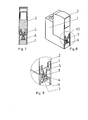
- a device combination for protection against overvoltages is shown.
- This consists of an approximately U-shaped lower part 1 and at least one plug-in with this overvoltage protection element having plug-in module 2.
- the plug-in module 2 is inserted into the corresponding recess of the lower part 1 and locked in the inserted position, between plug-in module 2 and lower part.
- 1 acting holding means or locking means are provided for example at 3.
- the corresponding locking means 3 can be unlocked or released, so that the plug-in module 2 can be removed from the lower part 1.
- a spring element 4 is arranged between the lower part 1 and plug-in module 2, which at plugged plug-in module according to FIG. 1 is biased and hidden in contours between lower part 1 and plug-in module 2 is pressed.
- the plug-in module 2 is moved counter to the insertion direction in a removal position, as shown in FIG. 2 is illustrated.
- a coil spring is arranged as a spring element 4 between the lower part 1 and plug-in module 2.
- the spring element 4 is held captive on the lower part 1.
- contacts 5 of the plug-in module 2 are contacted under spring force with contacts 6, which are part of the lower part 1.
- the spring force of the spring element 4 is dimensioned larger than the force between the contacts 5 and 6 of plug-in module 2 and lower part. 1 is generated, so that in this case the lifting of the plug-in module 2 takes place when unlocking the locking elements 3 by the force of the spring element 4.
- FIGS. 3 to 9 a device combination for protection against overvoltage with a preferably U-shaped lower part 1 and a plug-in with this, an overvoltage protection element having plug-in module 2 shown, wherein between plug-in module 2 and lower part 1 acting holding means or latching means are provided which in the inserted position of Intermesh parts and hold the parts in desired position, but which can be solved by manipulation and / or unlocked to remove the plug-in module 2 from the lower part 1 can.
- the holding means or locking means are not shown in the drawing. They are widely known in the art, so that can be dispensed with a concrete representation in the drawing.
- a spring element 4 is provided between the lower part 1 and plug-in module 2, which is biased plugged module 2 and displaced in dissolved or entrastetem holding means or locking means the plug-in module 2 opposite plugging direction in a removal position ,
- the lower part 1 can be connected in the usual way with connecting conductors, which in turn are contacted with plug contacts 6.
- the plug-in module 2 thus has corresponding plug elements 5, which are contacted with the overvoltage element of the plug-in module 2. This corresponds to the usual structure.
- the spring element 4 is formed according to the invention by at least one plug contact 6 or by a plug element 5.
- the spring element 4 is formed by the plug contact 6.
- the spring element 4 is formed by a plug contact 6, which is fork-shaped with resilient legs 7, wherein the corresponding part of the spring element 4, namely in the embodiment, the plug element 5, in the insertion direction has a wedge-like tapered contact surfaces 8, the in position according to FIGS. 6 to 8 rest on the legs 7 under resilient bias of the legs 7.
- the wedge-like contact surfaces 8 are formed on a solid metal contact element.
- the wedge-like contact surfaces 8 are formed on a bent sheet metal sheet bending contact element, which forms the male member 5.
- the invention provides a constructive solution with particularly simple means and at low cost, in which the disassembly of the plug-in module 2 from the lower part 1 is greatly facilitated for the user.
Landscapes
- Details Of Connecting Devices For Male And Female Coupling (AREA)
- Emergency Protection Circuit Devices (AREA)
Priority Applications (1)
| Application Number | Priority Date | Filing Date | Title |
|---|---|---|---|
| SI201131197A SI2432089T1 (sl) | 2010-09-20 | 2011-08-18 | Kombinacija naprav za zaščito pred prenapetostmi |
Applications Claiming Priority (2)
| Application Number | Priority Date | Filing Date | Title |
|---|---|---|---|
| DE202010012860U DE202010012860U1 (de) | 2010-09-20 | 2010-09-20 | Gerätekombination zum Schutz vor Überspannungen |
| DE102011013300A DE102011013300B4 (de) | 2010-09-20 | 2011-03-07 | Gerätekombination zum Schutz vor Überspannungen |
Publications (3)
| Publication Number | Publication Date |
|---|---|
| EP2432089A2 true EP2432089A2 (fr) | 2012-03-21 |
| EP2432089A3 EP2432089A3 (fr) | 2014-11-05 |
| EP2432089B1 EP2432089B1 (fr) | 2017-03-15 |
Family
ID=44532542
Family Applications (1)
| Application Number | Title | Priority Date | Filing Date |
|---|---|---|---|
| EP11006746.9A Active EP2432089B1 (fr) | 2010-09-20 | 2011-08-18 | Combinaison d'appareils pour la protection contre les surtensions |
Country Status (4)
| Country | Link |
|---|---|
| EP (1) | EP2432089B1 (fr) |
| CN (1) | CN102544833B (fr) |
| DE (1) | DE102011013300B4 (fr) |
| SI (1) | SI2432089T1 (fr) |
Cited By (4)
| Publication number | Priority date | Publication date | Assignee | Title |
|---|---|---|---|---|
| CN104641518A (zh) * | 2012-07-05 | 2015-05-20 | 奥宝贝特曼股份有限两合公司 | 可插接的过电压防护放电器 |
| EP2980936A1 (fr) * | 2014-08-01 | 2016-02-03 | ABB France | Cartouche de dispositif de protection d'installation électrique à connecteurs croisés |
| WO2019091733A1 (fr) * | 2017-11-07 | 2019-05-16 | Dehn + Söhne Gmbh + Co. Kg | Dispositif de protection contre les surtensions comprenant un boîtier isolant destiné à recevoir au moins un parasurtenseur |
| WO2023165761A1 (fr) * | 2022-03-02 | 2023-09-07 | Dehn Se | Dispositif de protection contre la surtension séparable et module de fiche pour un dispositif de protection contre la surtension séparable |
Families Citing this family (1)
| Publication number | Priority date | Publication date | Assignee | Title |
|---|---|---|---|---|
| DE102015214969A1 (de) * | 2015-08-05 | 2017-02-09 | Phoenix Contact Gmbh & Co. Kg | Überspannungsschutzgeräteensemble |
Citations (4)
| Publication number | Priority date | Publication date | Assignee | Title |
|---|---|---|---|---|
| DE3639533A1 (de) | 1986-11-20 | 1988-06-01 | Bettermann Obo Ohg | Steckbarer ueberspannungsableiter fuer elektrische anlagen |
| DE102006033274A1 (de) | 2005-02-09 | 2008-01-31 | Dehn + Söhne Gmbh + Co. Kg | Steckbare Gerätekombination zum Schutz vor Überspannungen |
| DE102008021210A1 (de) | 2008-01-30 | 2009-08-06 | Phoenix Contact Gmbh & Co. Kg | Überspannungsschutzgerät |
| DE102008017423A1 (de) | 2008-04-03 | 2009-10-15 | Phoenix Contact Gmbh & Co. Kg | Befestigungsvorrichtung zur Befestigung steckbarer elektrischer Gehäuse |
Family Cites Families (10)
| Publication number | Priority date | Publication date | Assignee | Title |
|---|---|---|---|---|
| DE1036356B (de) * | 1953-07-27 | 1958-08-14 | Siemens Ag | Schaltanlage mit ausziehbaren Geraeten oder Geraetebloecken |
| DE1912976U (de) * | 1964-11-27 | 1965-04-01 | Krone Gmbh | Halter fuer ueberspannungs-gasentladungsableiter. |
| US5273446A (en) * | 1992-11-02 | 1993-12-28 | Burndy Corporation | Zero separation force connector with wiping insertion |
| AT402991B (de) * | 1993-11-02 | 1997-10-27 | Felten & Guilleaume Ag Oester | Gerätesockel mit einsatzelement |
| DE10011385A1 (de) * | 2000-03-09 | 2001-09-13 | Abb Cmc Carl Maier Ag Schaffha | Einbaugerät für elektrische Niederspannungsinstallation |
| CN100517901C (zh) * | 2003-09-05 | 2009-07-22 | 上海电器科学研究所 | 电涌保护器可插拔模块及基座 |
| JP4695654B2 (ja) * | 2005-01-17 | 2011-06-08 | デーン+シェーネ ゲーエムベーハ+ツェオー.カーゲー | 特に過電圧に対する防護のための差込可能な組合せ型装置 |
| DE102005005914A1 (de) * | 2005-02-09 | 2006-08-10 | Dehn + Söhne Gmbh + Co. Kg | Steckbare Gerätekombination zum Schutz vor Überspannungen |
| CN101378159B (zh) * | 2007-08-27 | 2010-09-22 | 孙巍巍 | 浪涌保护器中的一种插接装置 |
| CN201315349Y (zh) * | 2008-11-07 | 2009-09-23 | 施耐德电器工业公司 | 浪涌保护器模块的连接机构 |
-
2011
- 2011-03-07 DE DE102011013300A patent/DE102011013300B4/de active Active
- 2011-08-18 SI SI201131197A patent/SI2432089T1/sl unknown
- 2011-08-18 EP EP11006746.9A patent/EP2432089B1/fr active Active
- 2011-09-20 CN CN201110310116.1A patent/CN102544833B/zh active Active
Patent Citations (4)
| Publication number | Priority date | Publication date | Assignee | Title |
|---|---|---|---|---|
| DE3639533A1 (de) | 1986-11-20 | 1988-06-01 | Bettermann Obo Ohg | Steckbarer ueberspannungsableiter fuer elektrische anlagen |
| DE102006033274A1 (de) | 2005-02-09 | 2008-01-31 | Dehn + Söhne Gmbh + Co. Kg | Steckbare Gerätekombination zum Schutz vor Überspannungen |
| DE102008021210A1 (de) | 2008-01-30 | 2009-08-06 | Phoenix Contact Gmbh & Co. Kg | Überspannungsschutzgerät |
| DE102008017423A1 (de) | 2008-04-03 | 2009-10-15 | Phoenix Contact Gmbh & Co. Kg | Befestigungsvorrichtung zur Befestigung steckbarer elektrischer Gehäuse |
Cited By (9)
| Publication number | Priority date | Publication date | Assignee | Title |
|---|---|---|---|---|
| CN104641518A (zh) * | 2012-07-05 | 2015-05-20 | 奥宝贝特曼股份有限两合公司 | 可插接的过电压防护放电器 |
| CN104641518B (zh) * | 2012-07-05 | 2016-11-02 | 奥宝贝特曼股份有限两合公司 | 可插接的过电压防护放电器 |
| EP2980936A1 (fr) * | 2014-08-01 | 2016-02-03 | ABB France | Cartouche de dispositif de protection d'installation électrique à connecteurs croisés |
| FR3024602A1 (fr) * | 2014-08-01 | 2016-02-05 | Abb France | Cartouche de dispositif de protection d’installation electrique a connecteurs croises |
| CN105322498A (zh) * | 2014-08-01 | 2016-02-10 | Abb法国公司 | 保护设备盒以及包括基底和该保护设备盒的保护设备 |
| US9941669B2 (en) | 2014-08-01 | 2018-04-10 | Abb Schweiz Ag | Protection device cartridge of an electrical installation with intersected connectors |
| CN105322498B (zh) * | 2014-08-01 | 2019-04-26 | Abb法国公司 | 保护设备盒以及包括基底和该保护设备盒的保护设备 |
| WO2019091733A1 (fr) * | 2017-11-07 | 2019-05-16 | Dehn + Söhne Gmbh + Co. Kg | Dispositif de protection contre les surtensions comprenant un boîtier isolant destiné à recevoir au moins un parasurtenseur |
| WO2023165761A1 (fr) * | 2022-03-02 | 2023-09-07 | Dehn Se | Dispositif de protection contre la surtension séparable et module de fiche pour un dispositif de protection contre la surtension séparable |
Also Published As
| Publication number | Publication date |
|---|---|
| HK1170854A1 (zh) | 2013-03-08 |
| SI2432089T1 (sl) | 2017-07-31 |
| EP2432089B1 (fr) | 2017-03-15 |
| EP2432089A3 (fr) | 2014-11-05 |
| DE102011013300B4 (de) | 2013-10-10 |
| DE102011013300A1 (de) | 2012-03-22 |
| CN102544833A (zh) | 2012-07-04 |
| CN102544833B (zh) | 2015-11-25 |
Similar Documents
| Publication | Publication Date | Title |
|---|---|---|
| DE102015114697B4 (de) | Halterahmen für Steckverbindermodule | |
| EP3235061B1 (fr) | Borne de connexion électrique | |
| EP2339701B1 (fr) | Connecteur à fiche de plaquettes doté d'un dispositif de verrouillage | |
| EP2839544B1 (fr) | Bornier de test | |
| EP3345253B1 (fr) | Châssis de maintien à force de rappel pour modules de connecteur à fiche | |
| EP3345257B1 (fr) | Armature de support pour connecteur modulaire | |
| DE102014106277B4 (de) | Ein Elektronikgehäuse mit einer Anschlussleiste für ein Elektronikgerät | |
| DE20313855U1 (de) | Anschlußvorrichtung zum Direktsteckanschluß von Leiterenden | |
| EP1752668A2 (fr) | Dispositif pour empêcher le mouvement axial d'un boulon avec une cannelure | |
| DE102017113063A1 (de) | Tragschienenbefestigung | |
| EP2432089A2 (fr) | Combinaison d'appareils pour la protection contre les surtensions | |
| DE102017108414A1 (de) | Schnellverschraubung, insbesondere zum Verbinden von mehrteiligen Baugruppen | |
| DE102014103203A1 (de) | Steckbare Gerätekombination | |
| DE202016106274U1 (de) | Eine Andockungsvorrichtung für Stromversorgungsanlagen | |
| DE102009023073A1 (de) | Brückenkontaktsystem | |
| DE19933834A1 (de) | Steckverbinder mit Kabelzugentlastung | |
| DE102012013404A1 (de) | Steckbarer Überspannungsableiter | |
| DE202010012860U1 (de) | Gerätekombination zum Schutz vor Überspannungen | |
| WO2017190824A1 (fr) | Dispositif d'accouplement | |
| DE102017112629A1 (de) | Steckverbinder mit einem Verriegelungsteil | |
| DE102007056252A1 (de) | Elektrischer Steckverbinder | |
| DE102004002850B4 (de) | Elektrischer Steckverbinder | |
| DE202017101632U1 (de) | Steckeranordnung und Verriegelungseinrichtung zur Verriegelung eines Gegensteckverbinders an einem Steckverbinder | |
| DE2853585A1 (de) | Kupplung fuer stromschienen | |
| DE102018107886B4 (de) | Steckverbindersystem mit einem bistabilen Element |
Legal Events
| Date | Code | Title | Description |
|---|---|---|---|
| PUAI | Public reference made under article 153(3) epc to a published international application that has entered the european phase |
Free format text: ORIGINAL CODE: 0009012 |
|
| AK | Designated contracting states |
Kind code of ref document: A2 Designated state(s): AL AT BE BG CH CY CZ DE DK EE ES FI FR GB GR HR HU IE IS IT LI LT LU LV MC MK MT NL NO PL PT RO RS SE SI SK SM TR |
|
| AX | Request for extension of the european patent |
Extension state: BA ME |
|
| PUAL | Search report despatched |
Free format text: ORIGINAL CODE: 0009013 |
|
| AK | Designated contracting states |
Kind code of ref document: A3 Designated state(s): AL AT BE BG CH CY CZ DE DK EE ES FI FR GB GR HR HU IE IS IT LI LT LU LV MC MK MT NL NO PL PT RO RS SE SI SK SM TR |
|
| AX | Request for extension of the european patent |
Extension state: BA ME |
|
| RIC1 | Information provided on ipc code assigned before grant |
Ipc: H01R 9/24 20060101ALI20140930BHEP Ipc: H01R 13/635 20060101ALI20140930BHEP Ipc: H01T 4/06 20060101AFI20140930BHEP |
|
| 17P | Request for examination filed |
Effective date: 20141121 |
|
| RBV | Designated contracting states (corrected) |
Designated state(s): AL AT BE BG CH CY CZ DE DK EE ES FI FR GB GR HR HU IE IS IT LI LT LU LV MC MK MT NL NO PL PT RO RS SE SI SK SM TR |
|
| GRAP | Despatch of communication of intention to grant a patent |
Free format text: ORIGINAL CODE: EPIDOSNIGR1 |
|
| RIC1 | Information provided on ipc code assigned before grant |
Ipc: H01T 4/06 20060101AFI20161116BHEP Ipc: H01R 9/24 20060101ALI20161116BHEP Ipc: H01R 13/635 20060101ALI20161116BHEP |
|
| INTG | Intention to grant announced |
Effective date: 20161201 |
|
| GRAS | Grant fee paid |
Free format text: ORIGINAL CODE: EPIDOSNIGR3 |
|
| GRAA | (expected) grant |
Free format text: ORIGINAL CODE: 0009210 |
|
| AK | Designated contracting states |
Kind code of ref document: B1 Designated state(s): AL AT BE BG CH CY CZ DE DK EE ES FI FR GB GR HR HU IE IS IT LI LT LU LV MC MK MT NL NO PL PT RO RS SE SI SK SM TR |
|
| REG | Reference to a national code |
Ref country code: CH Ref legal event code: EP Ref country code: GB Ref legal event code: FG4D Free format text: NOT ENGLISH |
|
| REG | Reference to a national code |
Ref country code: IE Ref legal event code: FG4D Free format text: LANGUAGE OF EP DOCUMENT: GERMAN |
|
| REG | Reference to a national code |
Ref country code: AT Ref legal event code: REF Ref document number: 876445 Country of ref document: AT Kind code of ref document: T Effective date: 20170415 |
|
| REG | Reference to a national code |
Ref country code: DE Ref legal event code: R096 Ref document number: 502011011822 Country of ref document: DE |
|
| REG | Reference to a national code |
Ref country code: NL Ref legal event code: MP Effective date: 20170315 |
|
| REG | Reference to a national code |
Ref country code: LT Ref legal event code: MG4D |
|
| PG25 | Lapsed in a contracting state [announced via postgrant information from national office to epo] |
Ref country code: FI Free format text: LAPSE BECAUSE OF FAILURE TO SUBMIT A TRANSLATION OF THE DESCRIPTION OR TO PAY THE FEE WITHIN THE PRESCRIBED TIME-LIMIT Effective date: 20170315 Ref country code: LT Free format text: LAPSE BECAUSE OF FAILURE TO SUBMIT A TRANSLATION OF THE DESCRIPTION OR TO PAY THE FEE WITHIN THE PRESCRIBED TIME-LIMIT Effective date: 20170315 Ref country code: GR Free format text: LAPSE BECAUSE OF FAILURE TO SUBMIT A TRANSLATION OF THE DESCRIPTION OR TO PAY THE FEE WITHIN THE PRESCRIBED TIME-LIMIT Effective date: 20170616 Ref country code: HR Free format text: LAPSE BECAUSE OF FAILURE TO SUBMIT A TRANSLATION OF THE DESCRIPTION OR TO PAY THE FEE WITHIN THE PRESCRIBED TIME-LIMIT Effective date: 20170315 Ref country code: NO Free format text: LAPSE BECAUSE OF FAILURE TO SUBMIT A TRANSLATION OF THE DESCRIPTION OR TO PAY THE FEE WITHIN THE PRESCRIBED TIME-LIMIT Effective date: 20170615 |
|
| REG | Reference to a national code |
Ref country code: FR Ref legal event code: PLFP Year of fee payment: 7 |
|
| PG25 | Lapsed in a contracting state [announced via postgrant information from national office to epo] |
Ref country code: LV Free format text: LAPSE BECAUSE OF FAILURE TO SUBMIT A TRANSLATION OF THE DESCRIPTION OR TO PAY THE FEE WITHIN THE PRESCRIBED TIME-LIMIT Effective date: 20170315 Ref country code: BG Free format text: LAPSE BECAUSE OF FAILURE TO SUBMIT A TRANSLATION OF THE DESCRIPTION OR TO PAY THE FEE WITHIN THE PRESCRIBED TIME-LIMIT Effective date: 20170615 Ref country code: SE Free format text: LAPSE BECAUSE OF FAILURE TO SUBMIT A TRANSLATION OF THE DESCRIPTION OR TO PAY THE FEE WITHIN THE PRESCRIBED TIME-LIMIT Effective date: 20170315 Ref country code: RS Free format text: LAPSE BECAUSE OF FAILURE TO SUBMIT A TRANSLATION OF THE DESCRIPTION OR TO PAY THE FEE WITHIN THE PRESCRIBED TIME-LIMIT Effective date: 20170315 |
|
| PG25 | Lapsed in a contracting state [announced via postgrant information from national office to epo] |
Ref country code: NL Free format text: LAPSE BECAUSE OF FAILURE TO SUBMIT A TRANSLATION OF THE DESCRIPTION OR TO PAY THE FEE WITHIN THE PRESCRIBED TIME-LIMIT Effective date: 20170315 |
|
| PG25 | Lapsed in a contracting state [announced via postgrant information from national office to epo] |
Ref country code: SK Free format text: LAPSE BECAUSE OF FAILURE TO SUBMIT A TRANSLATION OF THE DESCRIPTION OR TO PAY THE FEE WITHIN THE PRESCRIBED TIME-LIMIT Effective date: 20170315 Ref country code: EE Free format text: LAPSE BECAUSE OF FAILURE TO SUBMIT A TRANSLATION OF THE DESCRIPTION OR TO PAY THE FEE WITHIN THE PRESCRIBED TIME-LIMIT Effective date: 20170315 Ref country code: RO Free format text: LAPSE BECAUSE OF FAILURE TO SUBMIT A TRANSLATION OF THE DESCRIPTION OR TO PAY THE FEE WITHIN THE PRESCRIBED TIME-LIMIT Effective date: 20170315 Ref country code: ES Free format text: LAPSE BECAUSE OF FAILURE TO SUBMIT A TRANSLATION OF THE DESCRIPTION OR TO PAY THE FEE WITHIN THE PRESCRIBED TIME-LIMIT Effective date: 20170315 |
|
| PG25 | Lapsed in a contracting state [announced via postgrant information from national office to epo] |
Ref country code: SM Free format text: LAPSE BECAUSE OF FAILURE TO SUBMIT A TRANSLATION OF THE DESCRIPTION OR TO PAY THE FEE WITHIN THE PRESCRIBED TIME-LIMIT Effective date: 20170315 Ref country code: PT Free format text: LAPSE BECAUSE OF FAILURE TO SUBMIT A TRANSLATION OF THE DESCRIPTION OR TO PAY THE FEE WITHIN THE PRESCRIBED TIME-LIMIT Effective date: 20170717 Ref country code: IS Free format text: LAPSE BECAUSE OF FAILURE TO SUBMIT A TRANSLATION OF THE DESCRIPTION OR TO PAY THE FEE WITHIN THE PRESCRIBED TIME-LIMIT Effective date: 20170715 Ref country code: PL Free format text: LAPSE BECAUSE OF FAILURE TO SUBMIT A TRANSLATION OF THE DESCRIPTION OR TO PAY THE FEE WITHIN THE PRESCRIBED TIME-LIMIT Effective date: 20170315 |
|
| REG | Reference to a national code |
Ref country code: DE Ref legal event code: R097 Ref document number: 502011011822 Country of ref document: DE |
|
| PLBE | No opposition filed within time limit |
Free format text: ORIGINAL CODE: 0009261 |
|
| STAA | Information on the status of an ep patent application or granted ep patent |
Free format text: STATUS: NO OPPOSITION FILED WITHIN TIME LIMIT |
|
| PG25 | Lapsed in a contracting state [announced via postgrant information from national office to epo] |
Ref country code: DK Free format text: LAPSE BECAUSE OF FAILURE TO SUBMIT A TRANSLATION OF THE DESCRIPTION OR TO PAY THE FEE WITHIN THE PRESCRIBED TIME-LIMIT Effective date: 20170315 |
|
| 26N | No opposition filed |
Effective date: 20171218 |
|
| REG | Reference to a national code |
Ref country code: CH Ref legal event code: PL |
|
| PG25 | Lapsed in a contracting state [announced via postgrant information from national office to epo] |
Ref country code: MC Free format text: LAPSE BECAUSE OF FAILURE TO SUBMIT A TRANSLATION OF THE DESCRIPTION OR TO PAY THE FEE WITHIN THE PRESCRIBED TIME-LIMIT Effective date: 20170315 |
|
| GBPC | Gb: european patent ceased through non-payment of renewal fee |
Effective date: 20170818 |
|
| PG25 | Lapsed in a contracting state [announced via postgrant information from national office to epo] |
Ref country code: LI Free format text: LAPSE BECAUSE OF NON-PAYMENT OF DUE FEES Effective date: 20170831 Ref country code: CH Free format text: LAPSE BECAUSE OF NON-PAYMENT OF DUE FEES Effective date: 20170831 |
|
| REG | Reference to a national code |
Ref country code: IE Ref legal event code: MM4A |
|
| REG | Reference to a national code |
Ref country code: BE Ref legal event code: MM Effective date: 20170831 |
|
| PG25 | Lapsed in a contracting state [announced via postgrant information from national office to epo] |
Ref country code: LU Free format text: LAPSE BECAUSE OF NON-PAYMENT OF DUE FEES Effective date: 20170818 |
|
| PG25 | Lapsed in a contracting state [announced via postgrant information from national office to epo] |
Ref country code: GB Free format text: LAPSE BECAUSE OF NON-PAYMENT OF DUE FEES Effective date: 20170818 Ref country code: IE Free format text: LAPSE BECAUSE OF NON-PAYMENT OF DUE FEES Effective date: 20170818 |
|
| REG | Reference to a national code |
Ref country code: FR Ref legal event code: PLFP Year of fee payment: 8 |
|
| PG25 | Lapsed in a contracting state [announced via postgrant information from national office to epo] |
Ref country code: BE Free format text: LAPSE BECAUSE OF NON-PAYMENT OF DUE FEES Effective date: 20170831 |
|
| PG25 | Lapsed in a contracting state [announced via postgrant information from national office to epo] |
Ref country code: MT Free format text: LAPSE BECAUSE OF FAILURE TO SUBMIT A TRANSLATION OF THE DESCRIPTION OR TO PAY THE FEE WITHIN THE PRESCRIBED TIME-LIMIT Effective date: 20170315 |
|
| REG | Reference to a national code |
Ref country code: AT Ref legal event code: MM01 Ref document number: 876445 Country of ref document: AT Kind code of ref document: T Effective date: 20170818 |
|
| PG25 | Lapsed in a contracting state [announced via postgrant information from national office to epo] |
Ref country code: AT Free format text: LAPSE BECAUSE OF NON-PAYMENT OF DUE FEES Effective date: 20170818 |
|
| PG25 | Lapsed in a contracting state [announced via postgrant information from national office to epo] |
Ref country code: HU Free format text: LAPSE BECAUSE OF FAILURE TO SUBMIT A TRANSLATION OF THE DESCRIPTION OR TO PAY THE FEE WITHIN THE PRESCRIBED TIME-LIMIT; INVALID AB INITIO Effective date: 20110818 |
|
| PG25 | Lapsed in a contracting state [announced via postgrant information from national office to epo] |
Ref country code: CY Free format text: LAPSE BECAUSE OF NON-PAYMENT OF DUE FEES Effective date: 20170315 |
|
| PG25 | Lapsed in a contracting state [announced via postgrant information from national office to epo] |
Ref country code: MK Free format text: LAPSE BECAUSE OF FAILURE TO SUBMIT A TRANSLATION OF THE DESCRIPTION OR TO PAY THE FEE WITHIN THE PRESCRIBED TIME-LIMIT Effective date: 20170315 |
|
| PG25 | Lapsed in a contracting state [announced via postgrant information from national office to epo] |
Ref country code: TR Free format text: LAPSE BECAUSE OF FAILURE TO SUBMIT A TRANSLATION OF THE DESCRIPTION OR TO PAY THE FEE WITHIN THE PRESCRIBED TIME-LIMIT Effective date: 20170315 |
|
| PG25 | Lapsed in a contracting state [announced via postgrant information from national office to epo] |
Ref country code: AL Free format text: LAPSE BECAUSE OF FAILURE TO SUBMIT A TRANSLATION OF THE DESCRIPTION OR TO PAY THE FEE WITHIN THE PRESCRIBED TIME-LIMIT Effective date: 20170315 |
|
| P01 | Opt-out of the competence of the unified patent court (upc) registered |
Effective date: 20230509 |
|
| PGFP | Annual fee paid to national office [announced via postgrant information from national office to epo] |
Ref country code: IT Payment date: 20250825 Year of fee payment: 15 |
|
| PGFP | Annual fee paid to national office [announced via postgrant information from national office to epo] |
Ref country code: FR Payment date: 20250821 Year of fee payment: 15 |
|
| PGFP | Annual fee paid to national office [announced via postgrant information from national office to epo] |
Ref country code: CZ Payment date: 20250814 Year of fee payment: 15 |
|
| PGFP | Annual fee paid to national office [announced via postgrant information from national office to epo] |
Ref country code: SI Payment date: 20250821 Year of fee payment: 15 |
|
| PGFP | Annual fee paid to national office [announced via postgrant information from national office to epo] |
Ref country code: DE Payment date: 20251028 Year of fee payment: 15 |
|
| REG | Reference to a national code |
Ref country code: DE Ref legal event code: R082 Ref document number: 502011011822 Country of ref document: DE Representative=s name: KOECHLING, MARIETTA, M.SC B.ENG., DE |