EP2433543A2 - Staubsammelvorrichtung - Google Patents
Staubsammelvorrichtung Download PDFInfo
- Publication number
- EP2433543A2 EP2433543A2 EP11182810A EP11182810A EP2433543A2 EP 2433543 A2 EP2433543 A2 EP 2433543A2 EP 11182810 A EP11182810 A EP 11182810A EP 11182810 A EP11182810 A EP 11182810A EP 2433543 A2 EP2433543 A2 EP 2433543A2
- Authority
- EP
- European Patent Office
- Prior art keywords
- current
- value
- parameter
- threshold value
- dust collector
- Prior art date
- Legal status (The legal status is an assumption and is not a legal conclusion. Google has not performed a legal analysis and makes no representation as to the accuracy of the status listed.)
- Granted
Links
Images







Classifications
-
- A—HUMAN NECESSITIES
- A47—FURNITURE; DOMESTIC ARTICLES OR APPLIANCES; COFFEE MILLS; SPICE MILLS; SUCTION CLEANERS IN GENERAL
- A47L—DOMESTIC WASHING OR CLEANING; SUCTION CLEANERS IN GENERAL
- A47L7/00—Suction cleaners adapted for additional purposes; Tables with suction openings for cleaning purposes; Containers for cleaning articles by suction; Suction cleaners adapted to cleaning of brushes; Suction cleaners adapted to taking-up liquids
- A47L7/0095—Suction cleaners or attachments adapted to collect dust or waste from power tools
-
- A—HUMAN NECESSITIES
- A47—FURNITURE; DOMESTIC ARTICLES OR APPLIANCES; COFFEE MILLS; SPICE MILLS; SUCTION CLEANERS IN GENERAL
- A47L—DOMESTIC WASHING OR CLEANING; SUCTION CLEANERS IN GENERAL
- A47L9/00—Details or accessories of suction cleaners, e.g. mechanical means for controlling the suction or for effecting pulsating action; Storing devices specially adapted to suction cleaners or parts thereof; Carrying-vehicles specially adapted for suction cleaners
- A47L9/28—Installation of the electric equipment, e.g. adaptation or attachment to the suction cleaner; Controlling suction cleaners by electric means
- A47L9/2805—Parameters or conditions being sensed
-
- A—HUMAN NECESSITIES
- A47—FURNITURE; DOMESTIC ARTICLES OR APPLIANCES; COFFEE MILLS; SPICE MILLS; SUCTION CLEANERS IN GENERAL
- A47L—DOMESTIC WASHING OR CLEANING; SUCTION CLEANERS IN GENERAL
- A47L9/00—Details or accessories of suction cleaners, e.g. mechanical means for controlling the suction or for effecting pulsating action; Storing devices specially adapted to suction cleaners or parts thereof; Carrying-vehicles specially adapted for suction cleaners
- A47L9/28—Installation of the electric equipment, e.g. adaptation or attachment to the suction cleaner; Controlling suction cleaners by electric means
- A47L9/2836—Installation of the electric equipment, e.g. adaptation or attachment to the suction cleaner; Controlling suction cleaners by electric means characterised by the parts which are controlled
- A47L9/2842—Suction motors or blowers
-
- A—HUMAN NECESSITIES
- A47—FURNITURE; DOMESTIC ARTICLES OR APPLIANCES; COFFEE MILLS; SPICE MILLS; SUCTION CLEANERS IN GENERAL
- A47L—DOMESTIC WASHING OR CLEANING; SUCTION CLEANERS IN GENERAL
- A47L9/00—Details or accessories of suction cleaners, e.g. mechanical means for controlling the suction or for effecting pulsating action; Storing devices specially adapted to suction cleaners or parts thereof; Carrying-vehicles specially adapted for suction cleaners
- A47L9/28—Installation of the electric equipment, e.g. adaptation or attachment to the suction cleaner; Controlling suction cleaners by electric means
- A47L9/2857—User input or output elements for control, e.g. buttons, switches or displays
-
- A—HUMAN NECESSITIES
- A47—FURNITURE; DOMESTIC ARTICLES OR APPLIANCES; COFFEE MILLS; SPICE MILLS; SUCTION CLEANERS IN GENERAL
- A47L—DOMESTIC WASHING OR CLEANING; SUCTION CLEANERS IN GENERAL
- A47L9/00—Details or accessories of suction cleaners, e.g. mechanical means for controlling the suction or for effecting pulsating action; Storing devices specially adapted to suction cleaners or parts thereof; Carrying-vehicles specially adapted for suction cleaners
- A47L9/28—Installation of the electric equipment, e.g. adaptation or attachment to the suction cleaner; Controlling suction cleaners by electric means
- A47L9/2868—Arrangements for power supply of vacuum cleaners or the accessories thereof
-
- B—PERFORMING OPERATIONS; TRANSPORTING
- B23—MACHINE TOOLS; METAL-WORKING NOT OTHERWISE PROVIDED FOR
- B23D—PLANING; SLOTTING; SHEARING; BROACHING; SAWING; FILING; SCRAPING; LIKE OPERATIONS FOR WORKING METAL BY REMOVING MATERIAL, NOT OTHERWISE PROVIDED FOR
- B23D59/00—Accessories specially designed for sawing machines or sawing devices
- B23D59/006—Accessories specially designed for sawing machines or sawing devices for removing or collecting chips
- B23D59/0064—Accessories specially designed for sawing machines or sawing devices for removing or collecting chips by suction
-
- G—PHYSICS
- G01—MEASURING; TESTING
- G01R—MEASURING ELECTRIC VARIABLES; MEASURING MAGNETIC VARIABLES
- G01R19/00—Arrangements for measuring currents or voltages or for indicating presence or sign thereof
- G01R19/165—Indicating that current or voltage is either above or below a predetermined value or within or outside a predetermined range of values
- G01R19/16566—Circuits and arrangements for comparing voltage or current with one or several thresholds and for indicating the result not covered by subgroups G01R19/16504, G01R19/16528, G01R19/16533
- G01R19/16571—Circuits and arrangements for comparing voltage or current with one or several thresholds and for indicating the result not covered by subgroups G01R19/16504, G01R19/16528, G01R19/16533 comparing AC or DC current with one threshold, e.g. load current, over-current, surge current or fault current
Definitions
- the present invention relates to a dust collector which can be activated interlocking with activation of an electric power tool or the like.
- Patent Document 1 Japanese Unexamined Patent Application Publication No. 2008-36723
- an activation timing of the dust collector is sometimes inappropriate relative to an activation timing of the electric power tool in the aforementioned interlocking system. It is desirable to achieve an appropriate activation timing of a dust collector relative to an activation timing of an electric power tool.
- a dust collector for suctioning dust which includes an electric motor (5) for collecting dust, a power supply device (7), a parameter detection device (13), a determination device (13), and a current supply starting device (13).
- the power supply device (7) supplies electric power to outside.
- the parameter detection device (13) detects a parameter (hereinafter referred to as a "current parameter") which changes depending on a state of a supplied current supplied by the power supply device (7).
- the determination device (13) determines whether or not a value of the current parameter detected by the parameter detection device (13) satisfies a condition based on a threshold value stored in a first storage unit (ROM).
- the current supply starting device (13) starts current supply to the electric motor (5) when it is determined by the determination device (13) that the value of the current parameter satisfies the condition.
- an activation timing of the dust collector may be controlled to an appropriate timing.
- the parameter detection device (13) detects an integrated current value, which is obtained by integrating an absolute value of a current value of the supplied current from when supply of the supplied current is started, as the current parameter.
- the first storage unit stores a first threshold value indicating a threshold value of the integrated current value
- the determination device (13) determines that the value of the current parameter satisfies the condition when the value of the current parameter is equal to or more than the first threshold value.
- the parameter detection device (13) resets the current parameter to an initial value when an integrated time, which is obtained by integrating a time during which the current value of the supplied current is less than a second threshold value stored in a second storage unit (ROM), exceeds a third threshold value stored in a third storage unit (ROM).
- the power supply device (7) supplies electric power having a periodically changing current value, and when a time, during which the absolute value of the current value of the supplied current is more than "0" and also is equal to or more than a predetermined current value (i 0 ) that is less than a maximum current value, is referred to as a "current supply time" (T 2 ), the parameter detection device (13) detects, as the current parameter, an integrated value of the current supply time (T 2 ) from when supply of the supplied current is started.
- the first storage unit stores a fourth threshold value indicating a threshold value of the integrated value of the current supply time (T 2 ), and the determination device (13) determines that the value of the current parameter satisfies the condition when the value of the current parameter is equal to or more than the fourth threshold value.
- the power supply device (7) supplies electric power having a periodically changing current value, and when a state, in which the absolute value of the current value of the supplied current is more than "0" and also is equal to or more than a predetermined current value (i 0 ) that is less than a maximum current value, is referred to as a "current supplied state", a time during which the current supplied state is present is referred to as a “current supply time” (T 2 ), and a number of times of shifts to the current supplied state from when supply of the supplied current is started is referred to as a "counter value", the parameter detection device (13) detects the counter value as the current parameter, while making the current value correspond to the current supply time (T 2 ).
- the first storage unit (ROM) stores a fifth threshold value indicating a threshold value of the counter value corresponding to the current supply time (T 2 ), the fifth threshold value being set to be larger as the current supply time (T 2 ) is shorter, and the determination device (13) determines that the value of the current parameter satisfies the condition when the value of the current parameter is equal to or more than the fifth threshold value.
- the parameter detection device (13) resets the current parameter to an initial value when an integrated time, which is obtained by integrating a time during which the current supply time is unable to be detected, exceeds a sixth threshold value stored in a sixth storage unit (ROM).
- a condition changing device (27A, 27B) that is configured to change a value indicating the condition and is operable by a user.
- each of assigned reference letters and numerals in the above description is intended to indicate an example of a correspondence between each device in the present invention and a component in later-described embodiments.
- the each device in the present invention is not limited to the component represented by the reference letter or numeral in the embodiments.
- the dust collector 1 may be, for example, a dust collector which can be activated interlocking with activation of an electric power tool, such as an electric circular saw (a disk-shaped saw).
- an electric power tool such as an electric circular saw (a disk-shaped saw).
- dust such as sawdust can be rapidly suctioned by the dust collector 1 before the dust is scattered around.
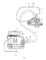
- an activation switch 3 of the dust collector 1 a suction power adjustment dial 4 (hereinafter simply referred to as "the adjustment dial 4") for adjusting suction power, an electric outlet 7 for supplying electric power to outside, etc. are provided in a front upper portion of the dust collector 1.
- an electric motor 5 for collecting dust (see FIG. 3 ) is activated when the activation switch 3 is turned to an "ON” state, while the electric motor 5 is stopped when the activation switch 3 is turned to an "OFF” state.
- an operation mode of the dust collector 1 is turned to an interlock mode.
- the interlock mode is a mode in which the electric motor 5 is activated and stopped interlocking with activation and stop of an electric power tool 50 (see FIG. 2 ) connected to the electric outlet 7.
- an extension cord 11 is integrated into a flexible hose 9 for suction.
- a power plug 51 of the electric power tool 50 is inserted into an electric outlet 11A of the extension cord 11, and a plug 11B of the extension cord 11 is inserted into the electric outlet 7 (see FIG. 1 )
- the electric power tool 50 can be indirectly connected to the electric outlet 7.
- a controller 2 of the dust collector 1 includes a CPU module 13, a current detection unit 15, a dust collector motor control unit 17 (hereinafter simply referred to as “the motor control unit 17”), a zero-cross detection unit 19, a control circuit power source 21 (hereinafter simply referred to as “the power source 21”), an activation switch 3, and the adjustment dial 4.
- the controller 2 controls operations of the electric motor 5 and the like.
- the CPU module 13 is an integrated combination of a CPU (Central Processing Unit), a ROM, a RAM, and an A/D converter.
- the CPU performs device control according to a program stored in the ROM.
- the ROM is a memory for storing programs to be executed by the CPU.
- the RAM is a memory for temporarily storing calculation results and the like.
- the A/D converter converts analog signals inputted to the CPU module 13 into digital signals.
- the current detection unit 15 detects an absolute value of a current value (hereinafter referred to as a "current absolute value") of a supplied current (alternating current in the present embodiment) which is supplied through the electric outlet 7. Then, in synchronization with starting of supply of the supplied current, the current detection unit 15 inputs an analog signal indicating the detected current absolute value to the A/D converter in the CPU module 13.
- a current absolute value a current value of a supplied current (alternating current in the present embodiment) which is supplied through the electric outlet 7. Then, in synchronization with starting of supply of the supplied current, the current detection unit 15 inputs an analog signal indicating the detected current absolute value to the A/D converter in the CPU module 13.
- the motor control unit 17 controls operation of the electric motor (electric motor for the dust collector) 5. Specifically, the motor control unit 17 adjusts an electric power supplied from a commercial power source (an AC power source) to an electric power (a voltage) corresponding to a suction power set by the adjustment dial 4, and supplies the adjusted electric power to the electric motor 5. The operation of the motor control unit 17 is controlled by the CPU module 13.
- the zero-cross detection unit 19 detects a timing when a voltage of the electric power supplied from the commercial power source becomes 0 volt.
- the CPU module 13 controls the motor control unit 17 such that power supply to the electric motor 5 is started at the timing when the voltage of the electric power supplied from the commercial power source becomes 0 volt.
- the power source 21 is a power source circuit that supplies electric power to drive control circuits such as the CPU module 13.
- the power source 21 converts the electric power supplied from the commercial power source into a direct current with a predetermined voltage, and supplies the electric power (direct current power) to the CPU module 13 and the like.
- a main switch 23 is a manual switch that opens and closes a circuit of the electric power supplied from the commercial power source through a power plug 1A (see FIG. 2 ) of the dust collector 1.
- the main switch 23 is included in the activation switch 3 shown in FIG. 1 .
- the main switch 23 When the activation switch 3 is in the "Interlock" or "ON” state, the main switch 23 is closed, and power supply to the power source 21, to the control circuits such as the CPU module 13, and to the electric outlet 7 is started, as well as power supply to the electric motor 5 becomes available.
- the CPU module 13 When the main switch 23 is closed and power supply is started, the CPU module 13 is activated, and a state of the activation switch 3 is detected. When the activation switch 3 is in the "ON" state, current supply to the electric motor 5 is started.
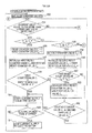
- Control steps (S1-S19) shown in FIG. 4 are performed at predetermined respective time intervals according to a timer (not shown) provided in the CPU module 13. Accordingly, an accumulated number of performed control steps is increased in proportion to an elapsed time from when the interlock mode is activated.
- a "time counter value” is a value indicating a level of an elapsed time.
- the elapsed time is a time that has elapsed from when the time counter value is set to an initial value (0).
- the elapsed time becomes longer in proportion to an increase of the time counter value.
- An integrated current value is a value obtained by integrating an absolute value of a current value of a supplied current from when current supply through the electric outlet 7 is started.
- the integrated current value is calculated by integrating only current values equal to or more than a later-described lower limit value Io, in order to exclude a noise current or the like flowing through the electric power tool 50.
- the lower limit value Io is a value that is smaller than a current value of a current which is supplied during normal operation of the electric power tool 50 and can be regarded as a current value of a noise current or the like.
- an initial value of the time counter value ("0" in the present embodiment) and an initial value of the integrated current value (“0" in the present embodiment) are stored in the RAM (S1). Then, a digital signal indicating a current value detected by the current detection unit 15, i.e., a signal converted by the A/D converter, is read (S2).
- the time counter value stored in the RAM is reset to the initial value (S7). Subsequently, the current value detected in S2, S3 is added to the integrated current value stored in the RAM, and thereby the integrated current value is updated (S9).
- the integrated current value is updated (S9), it is determined whether or not the updated integrated current value is equal to or more than a predetermined threshold value (hereinafter referred to as the "integrated threshold value ⁇ ") previously stored in the ROM (S11).
- the step S2 is performed again.
- current supply to the electric motor 5 is started (S13). Subsequently, it is determined whether or not the electric power tool 50 has stopped based on the current value detected by the current detection unit 15.
- the step S1 it is determined whether or not the updated time counter value is equal to or more than a threshold value (hereinafter the threshold value is referred to as the "time threshold value T 1 ") previously stored in the ROM (S19).
- the threshold value hereinafter the threshold value is referred to as the "time threshold value T 1 ”
- the step S2 is performed.
- the present embodiment has a feature that current supply to the electric motor 5 is started when it is determined that a value of a parameter (hereinafter referred to as a "current parameter"), which changes depending on a state of a supplied current supplied through the electric outlet 7, satisfies a predetermined condition.
- a current parameter a parameter that changes depending on a state of a supplied current supplied through the electric outlet 7, satisfies a predetermined condition.
- the integrated current value which is obtained by integrating the absolute value of the current value of the supplied current from when current supply is started, is treated as a current parameter.
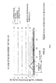
- the current parameter (the integrated current value) is equal to or more than the integrated threshold value ⁇ , current supply to the electric motor 5 is started (see FIG. 5 ).
- the larger an increase rate of the current parameter is, the earlier the current parameter reaches the integrated threshold value ⁇ (see FIG. 5 ).
- it is desirable in an electric power tool having a higher increase rate of the current parameter i.e., an electric power tool in which a larger current flows, that the dust collector 1 is activated rapidly interlocking with an activation timing of the electric power tool.
- the current parameter reaches the integrated threshold value ⁇ early, and an activation timing of the dust collector 1 becomes early.
- the activation timing of the dust collector 1 can be controlled to an appropriate timing.
- FIG. 5 a current (an inrush current) flowing in the electric power tool 50 at a moment (in a transition period) when power supply to the electric power tool 50 from the electric outlet 7 is started is larger.
- FIG. 6 shows an example of a noise current flowing in the electric power tool 50. Also in case of the noise current, a current value in a transition period is larger than a current value in a steady state (a steady-state current value). Therefore, if it is configured such that current supply to the electric motor 5 is started when a current value of a current flowing in the electric power tool 50 becomes equal to or more than a predetermined value, the noise current may cause malfunction of the dust collector 1.
- a steady-state current value of a noise current is smaller than a steady-state current value during use of an electric power tool. It is, therefore, advantageous that the integrated current value is treated as the current parameter.
- a configuration such that current supply to the electric motor 5 is started when the integrated current value becomes equal to or more than the integrated threshold value ⁇ enables activation of the electric motor 5 rapidly interlocking with the activation timing of the electric power tool, while eliminating influence of the noise current (that is, avoiding erroneous starting of current supply to the electric motor 5 by the noise current), as compared with a configuration such that current supply to the electric motor 5 is started when the current value becomes equal to or more than a predetermined value.
- the steady-state current value of the noise current is less than the lower limit value Io, and thus the current value of the noise current is not integrated.
- the current value in the transition period (the current value of the inrush current) is large even in the case of the noise current, and thus the current value of the noise current is integrated in the transition period.
- the current parameter (the integrated current value) is reset to the initial value.
- the current value of the noise current is additionally integrated to the integrated current value of the noise current, and thereby the integrated current value of the noise current becomes equal to or more than the integrated threshold value o.
- the electric outlet 7 corresponds to an example of a power supply device
- the controller which is constituted by the CPU module 13, the current detection unit 15, and the like corresponds to an example of a parameter detection device, an example of a determination device and an example of a current supply starting device.
- the integrated current value obtained by integrating the current value is used as the current parameter.
- whether or not to start current supply to the electric motor 5 is determined based on a product of a current supply time T 2 and a number of times of shifts to the current supplied state, that is, a value equivalent to an integrated value of the current supply time T 2 from when supply of the supplied current is started.
- the current supplied state means a state in which the absolute value of the current value of the supplied current is larger than "0" and also is equal to or more than a predetermined current value io, as shown in FIG. 7 .
- the current value io is smaller than a maximum current value.
- the current value io is larger than a value of a current which may be regarded as a noise current.
- the current supply time T 2 means a time during which a current supplied state is present. In other words, the current supply time T 2 is a time during which the absolute value of the current value of the supplied current is equal to or more than the current value io.
- the number of times of shifts to the current supplied state is referred to as the "counter value”. The number of times (the counter value) is counted from the moment when supply of the supplied current is started.
- a current value which is identical with the lower limit value Io in the first embodiment is adopted as a value of the current value i 0 .
- the current value io is indicated as a lower limit value i 0 .
- a frequency of the alternating current supplied through the electric outlet 7 is identical with a frequency of the commercial power source (the AC power source) regardless of the electric device, such as the electric power tool 50, connected to the electric outlet 7.
- the current supply time T 2 can be constant.
- the current supply time T 2 can have a value specific to each electric power tool 50 (a constant value). The larger the power consumption of the electric power tool 50 is, that is, the larger the current flowing to electric power tool 50 is, the longer the current supply time T 2 can be.
- the product of the current supply time T 2 and the counter value can be a parameter characteristic of increasing in conjunction with an increase of the integrated current value.
- the current supply time T 2 can have the value specific to each electric power tool 50 (the constant value) at the time of activation of the electric power tool 50. Therefore, in the second embodiment, the counter value is used as the current parameter.
- a plurality of threshold values to be compared with the current parameter (the counter value) are previously stored in accordance with a length of the current supply time T 2 (in other words, in accordance with a largeness of the current flowing in the electric power tool 50).
- the current parameter (the counter value) is compared with the threshold value corresponding to the current parameter, and thereby a determination is made on whether or not to start current supply to the electric motor 5.
- the product of the current supply time T 2 and the counter value is identical with an integrated value of the current supply time T 2 from when supply of the supplied current is started.
- the current detection unit 15 of a controller 2A in the second embodiment detects only a positive current out of supplied currents which are supplied through the electric outlet 7, and outputs the detected current to a comparator 25.
- the comparator 25 compares the current value of the inputted current and the lower limited value io, and outputs a signal to the CPU module 13 only while the current value of the inputted current is equal to or more than the lower limited value io, that is, only in the current supplied state. Accordingly, a time during which the comparator 25 outputs the signal is the current supply time T 2 .
- current supply to the electric motor 5 is started when the integrated value of the current supply time T 2 from when supply of the supplied current is started, that is, the product of the current supply time T 2 and the counter value becomes equal to or more than a value ⁇ ' which corresponds to the integrated threshold value ⁇ in the first embodiment.
- the number of times of shifts to the current supplied state (the counter value) is used as the current parameter, and current supply to the electric motor 5 is started when the current parameter becomes equal to or more than the threshold value which corresponds to the length of the current supply time T 2 and is previously stored in the ROM.
- FIG. 9A shows an example of a current waveform outputted from the current detection unit 15
- FIG. 9B is a chart showing an example of Case (a) above
- FIG. 9C is a chart showing an example of Case (b) above
- FIG. 9D is a chart showing an example of Case (c) above.
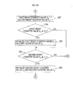
- initial values (both are "0" in the present embodiment) of a first counter value C 1 and a second counter value C 2 as well as initial values (both are “0” in the present embodiment) of a first reset counter value C 3 and a second reset counter value C 4 for determining timings to reset the first counter value C 1 and the second counter value C 2 to the initial values are stored in the RAM (S30).
- the first counter value C 1 means a counter value counted corresponding to the current supply time T 2 when the current supply time T 2 is equal to or more than the first current supply time T 3 previously stored in the ROM.
- the second counter value C 2 means a counter value counted corresponding to the current supply time T 2 when the current supply time T 2 is equal to or more than the second current supply time T 4 previously stored in the ROM.
- the step S55 is performed.
- the first reset counter value C 3 is equal to or more than the first reset threshold value C 5 (S51: YES)
- the step S31 is performed at a zero-cross timing of the supplied current in synchronization with a frequency of the supplied current supplied from the electric outlet 7, except when the electric motor 5 is activated. Therefore, when the first reset counter value C 3 is equal to or more than the first reset threshold value C 5 , the state, in which the current supply time T 2 is less than the first current supply time T 3 , has been continued for a time period that is determined by a product of the frequency of the supplied current and the first reset threshold value C 5 .
- the first reset counter value C 3 when the first reset counter value C 3 is equal to or more than the first reset threshold value C 5 , it is regarded that an electric power tool, which requires such a large current that the current supply time T 2 is equal to or more than the first current supply time T 3 , is not connected to the electric outlet 7 at least currently (when the step S53 is performed).
- the first counter value C 1 which is a current parameter to make a determination on the activation of the electric power tool requiring a large current, is reset to the initial value.
- the first reset counter value C 3 is equal to or more than the first reset threshold value C 5 (S59).
- the first counter value C 1 and the first reset counter value C 3 are reset to the respective initial values (S61) for the same reason as in S53, and then the step S63 is performed.
- the second reset counter value C 4 When it is determined that the second reset counter value C 4 is equal to or more than the second reset threshold value C 6 (S63: YES), the second counter value C 2 and the second reset counter value C 4 are reset to the respective initial values (S65). Then, the step S31 is performed again. On the other hand, when it is determined that the second reset counter value C 4 is less than the second reset threshold value C 6 (S63: NO), the second counter value C 2 or the like is not reset and the step S31 is performed again.
- the reason for resetting the second counter value C 2 and the second reset counter value C 4 to the respective initial values when the second reset counter value C 4 is equal to or more than the second reset threshold value C 6 is as follows: It can be regarded that an electric power tool, which requires such a large current that the current supply time T 2 is equal to or more than the second current supply time T 4 , is not connected to the electric outlet 7 currently (when the step S63 is performed) in a same manner as in S53.
- the case where the first counter value C 1 is equal to or more than the first threshold value ⁇ 1 , or the case where the second counter value C 2 is equal to or more than the second threshold value ⁇ 2 means the same as the case where the integrated value of the current supply time T 2 , from when supply of the supplied current is started (that is, when the current value equal to or more than the lower limit value io is detected in S31), becomes equal to or more than a predetermined threshold value.
- the configuration of the second embodiment may also be referred to as a configuration in which current supply to the electric motor 5 is started when the current parameter becomes equal to or more than a predetermined threshold value.
- the current parameter is the integrated value of the current supply time T 2 from when supply of the supplied current is started.
- the product of the current supply time T 2 and the first counter value C 1 , or the product of the current supply time T 2 and the second counter value C 2 is a parameter which is characteristic of becoming greater in conjunction with an increase of the integrated current value.
- the dust collector 1 When it is configured such that the threshold value corresponding to the number of times of shifts to the current supplied state becomes larger as a value of the current supply time T 2 is smaller, as in the second embodiment, the dust collector 1 is activated more rapidly interlocking with the activation timing of an electric power tool as a larger current flows in the electric power tool.
- the activation timing of the dust collector 1 may be controlled to an appropriate timing.
- the first counter value C 1 is reset to the initial value.
- the second counter value C 2 is reset to the initial value.
- the first counter value C 1 or the second counter value C 2 as the current parameter is reset to the initial value. Therefore, an unnecessary counter value (the current parameter) is not considered when determining the current supply timing to the electric motor 5, and thus an appropriate determination on the current supply timing to the electric motor 5 can be made.
- the electric outlet 7 corresponds to an example of a power supply device
- the controller which is constituted by the CPU module 13, the current detection unit 15, the comparator 25, and the like corresponds to an example of a parameter detection device, an example of a determination device and an example of a current supply starting device.
- the threshold values (the integrated threshold value ⁇ , the first threshold value ⁇ 1 , and the second threshold value ⁇ 2 ) to determine whether or not to start current supply to the electric motor 5 are fixed values stored in the ROM in the first and second embodiments, the threshold values are configured to be variable by a user's operation in a third embodiment.
- the dust collector 1 includes a condition changing device, such as an interlock sensitivity changeover switch 27A (hereinafter simply referred to as the "changeover switch 27A”) or an interlock sensitivity changeover dial 27B (hereinafter simply referred to as the “changeover dial 27B”), to change the threshold values.
- a condition changing device such as an interlock sensitivity changeover switch 27A (hereinafter simply referred to as the "changeover switch 27A”) or an interlock sensitivity changeover dial 27B (hereinafter simply referred to as the "changeover dial 27B”), to change the threshold values.
- the changeover switch 27A is a switch for stepwisely changing a time from when the electric power tool is activated until when the electric motor 5 is activated (hereinafter referred to as the "interlock sensitivity").
- the interlock sensitivity changeover dial 27B is a switch for continuously changing the interlock sensitivity. According to the third embodiment, the activation timing of the dust collector 1 may be further appropriately controlled.
- the threshold values cannot be directly changed since the threshold values are stored in the ROM. Therefore, in the third embodiment, a value obtained by multiplying each of the threshold value stored in the ROM by a parameter is used as a threshold value to determine whether or not to start current supply to the electric motor 5, and the interlock sensitivity is changed by changing the parameter using the changeover switch 27A or the like.
- FIG. 11A shows an example in which the third embodiment is applied to the controller in the first embodiment.
- FIG. 11B shows an example in which the third embodiment is applied to the controller in the second embodiment.
- the present invention is not limited to such configuration, but may be applied to a case where a direct current which periodically changes its current value is supplied. Especially in the first embodiment, a direct current with a constant current value may be used.
- the current waveform inputted to the comparator 25 is a waveform obtained by half-wave rectification of the current supplied through the electric outlet 7 in the second embodiment
- the present invention is not limited to such configuration, and a full-wave rectified waveform may be employed.
- the threshold value is indirectly changed in the third embodiment, the present invention is not limited to such configuration.
- the threshold value may be stored in a rewritable non-volatile storage device and be directly changed by the condition changing device, such as the changeover switch 27A.
- the present invention is not limited to such configuration.
- the present invention is not limited to such configuration.
- the integrated current value may be calculated using hardware such as an integration circuit.
- the integrated value of the current supply time T 2 as the current parameter that is, the first counter value C 1 or the like is detected (calculated) by the CPU module 13, the comparator 25, or the like
- the present invention is not limited to such configuration.
- the current parameter may be detected using hardware constituted by a combination of an integration circuit and a comparator or the like.
- While current supply to the electric motor 5 is stopped when a supplied current from the electric outlet 7 becomes unable to be detected, in the above-described embodiments, the present invention is not limited to such configuration.
- current supply to the electric motor 5 may be stopped when a predetermined time has elapsed after the supplied current from the electric outlet 7 becomes unable to be detected. This enables the electric motor 5 to be stopped after dust in the flexible hose 9 is suctioned.
- the present invention should not be limited to the above-described embodiments, but may be practiced in various forms within the gist of the present invention.
Landscapes
- Engineering & Computer Science (AREA)
- Mechanical Engineering (AREA)
- Control Of Electric Motors In General (AREA)
- Filtering Of Dispersed Particles In Gases (AREA)
- Electrostatic Separation (AREA)
- Cleaning In General (AREA)
- Portable Power Tools In General (AREA)
Applications Claiming Priority (1)
| Application Number | Priority Date | Filing Date | Title |
|---|---|---|---|
| JP2010215823A JP5618731B2 (ja) | 2010-09-27 | 2010-09-27 | 集塵機 |
Publications (3)
| Publication Number | Publication Date |
|---|---|
| EP2433543A2 true EP2433543A2 (de) | 2012-03-28 |
| EP2433543A3 EP2433543A3 (de) | 2013-03-06 |
| EP2433543B1 EP2433543B1 (de) | 2014-04-02 |
Family
ID=44719499
Family Applications (1)
| Application Number | Title | Priority Date | Filing Date |
|---|---|---|---|
| EP11182810.9A Not-in-force EP2433543B1 (de) | 2010-09-27 | 2011-09-26 | Staubsammelvorrichtung |
Country Status (5)
| Country | Link |
|---|---|
| US (1) | US20120073077A1 (de) |
| EP (1) | EP2433543B1 (de) |
| JP (1) | JP5618731B2 (de) |
| CN (1) | CN102415851B (de) |
| RU (1) | RU2011139266A (de) |
Cited By (5)
| Publication number | Priority date | Publication date | Assignee | Title |
|---|---|---|---|---|
| DE102012224429A1 (de) | 2012-12-27 | 2014-07-03 | Robert Bosch Gmbh | Werkzeugmaschinenfluidstromerzeugungsvorrichtung |
| EP2777464A3 (de) * | 2013-03-15 | 2015-01-07 | Black & Decker Inc. | Kabelklemmenstromsensor für Staubsammler |
| EP2878249A1 (de) * | 2013-10-31 | 2015-06-03 | Metabowerke GmbH | Mehrzweckstaubsauger |
| WO2015162193A1 (de) * | 2014-04-23 | 2015-10-29 | Hilti Aktiengesellschaft | Modiwechsel bei staubsaugervorrichtung |
| FI131333B1 (en) * | 2022-02-25 | 2025-02-24 | Mirka Ltd | Dust extractor having an electric outlet connectable to a power tool |
Families Citing this family (28)
| Publication number | Priority date | Publication date | Assignee | Title |
|---|---|---|---|---|
| US9776296B2 (en) | 2008-05-09 | 2017-10-03 | Milwaukee Electric Tool Corporation | Power tool dust collector |
| JP5539020B2 (ja) * | 2010-05-20 | 2014-07-02 | 株式会社マキタ | 切断工具の集塵装置 |
| JP5937418B2 (ja) * | 2012-05-01 | 2016-06-22 | 株式会社マキタ | 流体装置 |
| CN204833259U (zh) | 2012-07-17 | 2015-12-02 | 米沃奇电动工具公司 | 电动工具及电动工具系统 |
| JP6038715B2 (ja) * | 2013-04-10 | 2016-12-07 | 株式会社マキタ | 集塵機の連動システム |
| USD741557S1 (en) | 2014-01-15 | 2015-10-20 | Milwaukee Electric Tool Corporation | Dust collector |
| USD742081S1 (en) | 2014-01-15 | 2015-10-27 | Milwaukee Electric Tool Corporation | Dust collector |
| EP3009058B1 (de) * | 2014-10-13 | 2021-02-24 | Guido Valentini | Pneumatisch an ein Elektrowerkzeug angeschlossener Staubsauger, Verfahren zur Steuerung der Betriebsparameter solch eines Staubsaugers und Elektrowerkzeug zum pneumatischen Anschließen an solch einen Staubsauger |
| CN105629778B (zh) * | 2014-11-28 | 2019-05-28 | 天佑电器(苏州)有限公司 | 一种组合电动工具协同系统及方法 |
| JP6408371B2 (ja) * | 2014-12-17 | 2018-10-17 | 株式会社マキタ | 電動工具及び集塵機 |
| US20170197285A1 (en) * | 2015-08-28 | 2017-07-13 | Mark J. DRAGAN | Collecting sawdust and other debris from power saws |
| US9956626B2 (en) * | 2016-03-05 | 2018-05-01 | Siruceo Dustless LLC | Dustless table saw |
| JP7098603B2 (ja) | 2017-03-31 | 2022-07-11 | 株式会社マキタ | 電動工具 |
| EP3391995A1 (de) * | 2017-04-20 | 2018-10-24 | HILTI Aktiengesellschaft | Staubhaube für einen trennschleifer |
| JP6991743B2 (ja) | 2017-05-30 | 2022-01-13 | 株式会社マキタ | 電動工具 |
| WO2019009938A1 (en) | 2017-07-05 | 2019-01-10 | Milwaukee Electric Tool Corporation | ADAPTERS FOR COMMUNICATION BETWEEN ELECTRIC TOOLS |
| EP3505034B1 (de) | 2017-12-28 | 2025-02-12 | Makita Corporation | Verriegelungsadapter und verfahren zum formschlüssigen betreiben der elektrischen vorrichtung mit einer arbeitsmaschine |
| JP7225569B2 (ja) * | 2018-05-31 | 2023-02-21 | 工機ホールディングス株式会社 | 電動工具、集塵機、および無線連動システム |
| DE102018210682A1 (de) * | 2018-06-29 | 2020-01-02 | Robert Bosch Gmbh | System aus Sauggerät und Handwerkzeugmaschine |
| US11011053B2 (en) | 2018-07-31 | 2021-05-18 | Tti (Macao Commercial Offshore) Limited | Systems and methods for remote power tool device control |
| EP3883727A4 (de) | 2018-11-19 | 2023-03-15 | Milwaukee Electric Tool Corporation | Staubsammler mit filterreinigungsmechanismus |
| USD920608S1 (en) * | 2019-02-15 | 2021-05-25 | Black & Decker Inc. | Vacuum |
| USD912342S1 (en) * | 2019-03-04 | 2021-03-02 | Black & Decker Inc. | Vacuum |
| USD933317S1 (en) * | 2019-03-07 | 2021-10-12 | Black & Decker Inc. | Vacuum |
| JP2020157423A (ja) * | 2019-03-26 | 2020-10-01 | 株式会社マキタ | 集塵システム |
| US12273937B2 (en) | 2021-02-16 | 2025-04-08 | Milwaukee Electric Tool Corporation | Communication between a wireless dust extractor and a power tool |
| EP4091514B1 (de) * | 2021-05-20 | 2023-07-12 | Guido Valentini | Saugvorrichtung und saugschlauch für solch eine saugvorrichtung |
| WO2026010543A1 (en) * | 2024-07-04 | 2026-01-08 | Husqvarna Ab | Electrical energy storage devices for floor saws and other types of construction equipment |
Citations (1)
| Publication number | Priority date | Publication date | Assignee | Title |
|---|---|---|---|---|
| JP2008036723A (ja) | 2006-08-01 | 2008-02-21 | Makita Corp | 集塵機の連動システム |
Family Cites Families (9)
| Publication number | Priority date | Publication date | Assignee | Title |
|---|---|---|---|---|
| GB1273428A (en) * | 1969-08-01 | 1972-05-10 | Standard Telephones Cables Ltd | Improvements in or relating to measuring instruments |
| US4998098A (en) * | 1989-01-26 | 1991-03-05 | Schweitzer Engineering Laboratories Inc. | Overvoltage detector to indicate voltage to a remote monitor |
| US6348816B1 (en) * | 2000-12-28 | 2002-02-19 | Agere Systems Guardian Corp. | Tracking percent overload signal as indicator of output signal magnitude |
| JP4550357B2 (ja) * | 2002-12-16 | 2010-09-22 | 株式会社マキタ | 集塵機の連動システム |
| JP4674506B2 (ja) * | 2005-08-05 | 2011-04-20 | パナソニック株式会社 | 電気掃除機 |
| US20080022479A1 (en) * | 2006-06-30 | 2008-01-31 | Kong Zhao | Power tool combination and synchronization control device |
| US8443485B2 (en) * | 2008-01-18 | 2013-05-21 | Black & Decker Inc. | Outlet box for power tool sense |
| JP5197300B2 (ja) * | 2008-10-21 | 2013-05-15 | 株式会社マキタ | コード付きホース及び集塵機 |
| JP5446257B2 (ja) * | 2008-12-26 | 2014-03-19 | 日立工機株式会社 | 集塵機 |
-
2010
- 2010-09-27 JP JP2010215823A patent/JP5618731B2/ja not_active Expired - Fee Related
-
2011
- 2011-08-31 CN CN201110260510.9A patent/CN102415851B/zh not_active Expired - Fee Related
- 2011-09-19 US US13/235,733 patent/US20120073077A1/en not_active Abandoned
- 2011-09-26 EP EP11182810.9A patent/EP2433543B1/de not_active Not-in-force
- 2011-09-26 RU RU2011139266/02A patent/RU2011139266A/ru not_active Application Discontinuation
Patent Citations (1)
| Publication number | Priority date | Publication date | Assignee | Title |
|---|---|---|---|---|
| JP2008036723A (ja) | 2006-08-01 | 2008-02-21 | Makita Corp | 集塵機の連動システム |
Cited By (8)
| Publication number | Priority date | Publication date | Assignee | Title |
|---|---|---|---|---|
| DE102012224429A1 (de) | 2012-12-27 | 2014-07-03 | Robert Bosch Gmbh | Werkzeugmaschinenfluidstromerzeugungsvorrichtung |
| EP2777464A3 (de) * | 2013-03-15 | 2015-01-07 | Black & Decker Inc. | Kabelklemmenstromsensor für Staubsammler |
| EP2878249A1 (de) * | 2013-10-31 | 2015-06-03 | Metabowerke GmbH | Mehrzweckstaubsauger |
| EP3788921A1 (de) * | 2013-10-31 | 2021-03-10 | Metabowerke GmbH | Mehrzweckstaubsauger |
| WO2015162193A1 (de) * | 2014-04-23 | 2015-10-29 | Hilti Aktiengesellschaft | Modiwechsel bei staubsaugervorrichtung |
| FI131333B1 (en) * | 2022-02-25 | 2025-02-24 | Mirka Ltd | Dust extractor having an electric outlet connectable to a power tool |
| EP4482364A4 (de) * | 2022-02-25 | 2026-02-25 | Mirka Ltd | Staubabsaugvorrichtung mit einem an ein elektrowerkzeug anschliessbaren elektrischen auslass |
| US12588791B2 (en) | 2022-02-25 | 2026-03-31 | Mirka Ltd | Dust extractor having an electric outlet connectable to a power tool |
Also Published As
| Publication number | Publication date |
|---|---|
| US20120073077A1 (en) | 2012-03-29 |
| JP5618731B2 (ja) | 2014-11-05 |
| JP2012071218A (ja) | 2012-04-12 |
| RU2011139266A (ru) | 2013-04-10 |
| EP2433543B1 (de) | 2014-04-02 |
| CN102415851B (zh) | 2014-09-03 |
| CN102415851A (zh) | 2012-04-18 |
| EP2433543A3 (de) | 2013-03-06 |
Similar Documents
| Publication | Publication Date | Title |
|---|---|---|
| EP2433543B1 (de) | Staubsammelvorrichtung | |
| US8368333B2 (en) | Motor with circuits for protecting motor from input power outages or surges | |
| US11496055B2 (en) | Power converter, switch control circuit and short circuit detection method for current sensing resistor of the power converter | |
| US9263938B2 (en) | Power factor correction | |
| EP2175542A2 (de) | Ladegerät | |
| US4849681A (en) | Battery-powered device | |
| KR101020603B1 (ko) | 자동문용 모터 제어장치 및 제어방법 | |
| EP2702674B1 (de) | Leistungsfaktorkorrektur | |
| JP6308656B2 (ja) | 電源装置及び電圧源接続判定回路 | |
| JP6075048B2 (ja) | スイッチング電源装置の制御回路 | |
| KR101284492B1 (ko) | 전기 진공 청소기 | |
| WO2018126167A1 (en) | Primary side burst mode controller for llc converter | |
| US20070050094A1 (en) | Electric vacuum cleaner | |
| EP3185257B1 (de) | Timervorrichtung | |
| JP4706649B2 (ja) | 2線式スイッチ装置 | |
| KR101178193B1 (ko) | 자동으로 대기전력 차단기능을 갖는 콘센트장치및 그 제어방법 | |
| JP3961868B2 (ja) | 電力変換装置 | |
| KR100332787B1 (ko) | 인버터 에어컨의 이상 검출 장치 및 방법 | |
| KR100867192B1 (ko) | 전원제어장치와 전원공급장치의 동작모드 제어장치 및 그방법 | |
| JPH062917A (ja) | 空気調和機の制御方法 | |
| KR101848723B1 (ko) | 대기전력 차단용 콘센트 | |
| HK1149643A (en) | Brushless dc motor with soft-starting of pwm signals | |
| JP2003093297A (ja) | 電気掃除機 |
Legal Events
| Date | Code | Title | Description |
|---|---|---|---|
| PUAI | Public reference made under article 153(3) epc to a published international application that has entered the european phase |
Free format text: ORIGINAL CODE: 0009012 |
|
| AK | Designated contracting states |
Kind code of ref document: A2 Designated state(s): AL AT BE BG CH CY CZ DE DK EE ES FI FR GB GR HR HU IE IS IT LI LT LU LV MC MK MT NL NO PL PT RO RS SE SI SK SM TR |
|
| AX | Request for extension of the european patent |
Extension state: BA ME |
|
| PUAL | Search report despatched |
Free format text: ORIGINAL CODE: 0009013 |
|
| AK | Designated contracting states |
Kind code of ref document: A3 Designated state(s): AL AT BE BG CH CY CZ DE DK EE ES FI FR GB GR HR HU IE IS IT LI LT LU LV MC MK MT NL NO PL PT RO RS SE SI SK SM TR |
|
| AX | Request for extension of the european patent |
Extension state: BA ME |
|
| RIC1 | Information provided on ipc code assigned before grant |
Ipc: A47L 7/00 20060101ALI20130131BHEP Ipc: B23D 59/00 20060101ALI20130131BHEP Ipc: A47L 9/28 20060101AFI20130131BHEP Ipc: G01R 19/165 20060101ALI20130131BHEP Ipc: B23Q 11/00 20060101ALI20130131BHEP |
|
| 17P | Request for examination filed |
Effective date: 20130829 |
|
| RBV | Designated contracting states (corrected) |
Designated state(s): AL AT BE BG CH CY CZ DE DK EE ES FI FR GB GR HR HU IE IS IT LI LT LU LV MC MK MT NL NO PL PT RO RS SE SI SK SM TR |
|
| GRAP | Despatch of communication of intention to grant a patent |
Free format text: ORIGINAL CODE: EPIDOSNIGR1 |
|
| INTG | Intention to grant announced |
Effective date: 20131024 |
|
| GRAS | Grant fee paid |
Free format text: ORIGINAL CODE: EPIDOSNIGR3 |
|
| GRAA | (expected) grant |
Free format text: ORIGINAL CODE: 0009210 |
|
| AK | Designated contracting states |
Kind code of ref document: B1 Designated state(s): AL AT BE BG CH CY CZ DE DK EE ES FI FR GB GR HR HU IE IS IT LI LT LU LV MC MK MT NL NO PL PT RO RS SE SI SK SM TR |
|
| REG | Reference to a national code |
Ref country code: GB Ref legal event code: FG4D |
|
| REG | Reference to a national code |
Ref country code: CH Ref legal event code: EP Ref country code: AT Ref legal event code: REF Ref document number: 659577 Country of ref document: AT Kind code of ref document: T Effective date: 20140415 |
|
| REG | Reference to a national code |
Ref country code: IE Ref legal event code: FG4D |
|
| REG | Reference to a national code |
Ref country code: DE Ref legal event code: R096 Ref document number: 602011005856 Country of ref document: DE Effective date: 20140508 |
|
| RIN2 | Information on inventor provided after grant (corrected) |
Inventor name: ISHIKAWA, GOSHI Inventor name: YOSHIDA, KAZUHIKO |
|
| REG | Reference to a national code |
Ref country code: AT Ref legal event code: MK05 Ref document number: 659577 Country of ref document: AT Kind code of ref document: T Effective date: 20140402 |
|
| REG | Reference to a national code |
Ref country code: NL Ref legal event code: VDEP Effective date: 20140402 |
|
| REG | Reference to a national code |
Ref country code: LT Ref legal event code: MG4D |
|
| PG25 | Lapsed in a contracting state [announced via postgrant information from national office to epo] |
Ref country code: GR Free format text: LAPSE BECAUSE OF FAILURE TO SUBMIT A TRANSLATION OF THE DESCRIPTION OR TO PAY THE FEE WITHIN THE PRESCRIBED TIME-LIMIT Effective date: 20140703 Ref country code: BG Free format text: LAPSE BECAUSE OF FAILURE TO SUBMIT A TRANSLATION OF THE DESCRIPTION OR TO PAY THE FEE WITHIN THE PRESCRIBED TIME-LIMIT Effective date: 20140702 Ref country code: FI Free format text: LAPSE BECAUSE OF FAILURE TO SUBMIT A TRANSLATION OF THE DESCRIPTION OR TO PAY THE FEE WITHIN THE PRESCRIBED TIME-LIMIT Effective date: 20140402 Ref country code: CY Free format text: LAPSE BECAUSE OF FAILURE TO SUBMIT A TRANSLATION OF THE DESCRIPTION OR TO PAY THE FEE WITHIN THE PRESCRIBED TIME-LIMIT Effective date: 20140402 Ref country code: NO Free format text: LAPSE BECAUSE OF FAILURE TO SUBMIT A TRANSLATION OF THE DESCRIPTION OR TO PAY THE FEE WITHIN THE PRESCRIBED TIME-LIMIT Effective date: 20140702 Ref country code: CZ Free format text: LAPSE BECAUSE OF FAILURE TO SUBMIT A TRANSLATION OF THE DESCRIPTION OR TO PAY THE FEE WITHIN THE PRESCRIBED TIME-LIMIT Effective date: 20140402 Ref country code: LT Free format text: LAPSE BECAUSE OF FAILURE TO SUBMIT A TRANSLATION OF THE DESCRIPTION OR TO PAY THE FEE WITHIN THE PRESCRIBED TIME-LIMIT Effective date: 20140402 Ref country code: NL Free format text: LAPSE BECAUSE OF FAILURE TO SUBMIT A TRANSLATION OF THE DESCRIPTION OR TO PAY THE FEE WITHIN THE PRESCRIBED TIME-LIMIT Effective date: 20140402 Ref country code: IS Free format text: LAPSE BECAUSE OF FAILURE TO SUBMIT A TRANSLATION OF THE DESCRIPTION OR TO PAY THE FEE WITHIN THE PRESCRIBED TIME-LIMIT Effective date: 20140802 |
|
| PG25 | Lapsed in a contracting state [announced via postgrant information from national office to epo] |
Ref country code: ES Free format text: LAPSE BECAUSE OF FAILURE TO SUBMIT A TRANSLATION OF THE DESCRIPTION OR TO PAY THE FEE WITHIN THE PRESCRIBED TIME-LIMIT Effective date: 20140402 Ref country code: LV Free format text: LAPSE BECAUSE OF FAILURE TO SUBMIT A TRANSLATION OF THE DESCRIPTION OR TO PAY THE FEE WITHIN THE PRESCRIBED TIME-LIMIT Effective date: 20140402 Ref country code: RS Free format text: LAPSE BECAUSE OF FAILURE TO SUBMIT A TRANSLATION OF THE DESCRIPTION OR TO PAY THE FEE WITHIN THE PRESCRIBED TIME-LIMIT Effective date: 20140402 Ref country code: SE Free format text: LAPSE BECAUSE OF FAILURE TO SUBMIT A TRANSLATION OF THE DESCRIPTION OR TO PAY THE FEE WITHIN THE PRESCRIBED TIME-LIMIT Effective date: 20140402 Ref country code: HR Free format text: LAPSE BECAUSE OF FAILURE TO SUBMIT A TRANSLATION OF THE DESCRIPTION OR TO PAY THE FEE WITHIN THE PRESCRIBED TIME-LIMIT Effective date: 20140402 Ref country code: PL Free format text: LAPSE BECAUSE OF FAILURE TO SUBMIT A TRANSLATION OF THE DESCRIPTION OR TO PAY THE FEE WITHIN THE PRESCRIBED TIME-LIMIT Effective date: 20140402 Ref country code: AT Free format text: LAPSE BECAUSE OF FAILURE TO SUBMIT A TRANSLATION OF THE DESCRIPTION OR TO PAY THE FEE WITHIN THE PRESCRIBED TIME-LIMIT Effective date: 20140402 |
|
| PG25 | Lapsed in a contracting state [announced via postgrant information from national office to epo] |
Ref country code: PT Free format text: LAPSE BECAUSE OF FAILURE TO SUBMIT A TRANSLATION OF THE DESCRIPTION OR TO PAY THE FEE WITHIN THE PRESCRIBED TIME-LIMIT Effective date: 20140804 |
|
| REG | Reference to a national code |
Ref country code: DE Ref legal event code: R097 Ref document number: 602011005856 Country of ref document: DE |
|
| PG25 | Lapsed in a contracting state [announced via postgrant information from national office to epo] |
Ref country code: EE Free format text: LAPSE BECAUSE OF FAILURE TO SUBMIT A TRANSLATION OF THE DESCRIPTION OR TO PAY THE FEE WITHIN THE PRESCRIBED TIME-LIMIT Effective date: 20140402 Ref country code: SK Free format text: LAPSE BECAUSE OF FAILURE TO SUBMIT A TRANSLATION OF THE DESCRIPTION OR TO PAY THE FEE WITHIN THE PRESCRIBED TIME-LIMIT Effective date: 20140402 Ref country code: BE Free format text: LAPSE BECAUSE OF FAILURE TO SUBMIT A TRANSLATION OF THE DESCRIPTION OR TO PAY THE FEE WITHIN THE PRESCRIBED TIME-LIMIT Effective date: 20140402 Ref country code: RO Free format text: LAPSE BECAUSE OF FAILURE TO SUBMIT A TRANSLATION OF THE DESCRIPTION OR TO PAY THE FEE WITHIN THE PRESCRIBED TIME-LIMIT Effective date: 20140402 Ref country code: DK Free format text: LAPSE BECAUSE OF FAILURE TO SUBMIT A TRANSLATION OF THE DESCRIPTION OR TO PAY THE FEE WITHIN THE PRESCRIBED TIME-LIMIT Effective date: 20140402 |
|
| PLBE | No opposition filed within time limit |
Free format text: ORIGINAL CODE: 0009261 |
|
| STAA | Information on the status of an ep patent application or granted ep patent |
Free format text: STATUS: NO OPPOSITION FILED WITHIN TIME LIMIT |
|
| PG25 | Lapsed in a contracting state [announced via postgrant information from national office to epo] |
Ref country code: RS Free format text: LAPSE BECAUSE OF FAILURE TO SUBMIT A TRANSLATION OF THE DESCRIPTION OR TO PAY THE FEE WITHIN THE PRESCRIBED TIME-LIMIT Effective date: 20140716 |
|
| 26N | No opposition filed |
Effective date: 20150106 |
|
| PG25 | Lapsed in a contracting state [announced via postgrant information from national office to epo] |
Ref country code: IT Free format text: LAPSE BECAUSE OF FAILURE TO SUBMIT A TRANSLATION OF THE DESCRIPTION OR TO PAY THE FEE WITHIN THE PRESCRIBED TIME-LIMIT Effective date: 20140402 |
|
| REG | Reference to a national code |
Ref country code: DE Ref legal event code: R097 Ref document number: 602011005856 Country of ref document: DE Effective date: 20150106 |
|
| PG25 | Lapsed in a contracting state [announced via postgrant information from national office to epo] |
Ref country code: LU Free format text: LAPSE BECAUSE OF FAILURE TO SUBMIT A TRANSLATION OF THE DESCRIPTION OR TO PAY THE FEE WITHIN THE PRESCRIBED TIME-LIMIT Effective date: 20140926 Ref country code: MC Free format text: LAPSE BECAUSE OF FAILURE TO SUBMIT A TRANSLATION OF THE DESCRIPTION OR TO PAY THE FEE WITHIN THE PRESCRIBED TIME-LIMIT Effective date: 20140402 |
|
| REG | Reference to a national code |
Ref country code: CH Ref legal event code: PL |
|
| REG | Reference to a national code |
Ref country code: IE Ref legal event code: MM4A |
|
| REG | Reference to a national code |
Ref country code: FR Ref legal event code: ST Effective date: 20150529 |
|
| PG25 | Lapsed in a contracting state [announced via postgrant information from national office to epo] |
Ref country code: LI Free format text: LAPSE BECAUSE OF NON-PAYMENT OF DUE FEES Effective date: 20140930 Ref country code: CH Free format text: LAPSE BECAUSE OF NON-PAYMENT OF DUE FEES Effective date: 20140930 Ref country code: SI Free format text: LAPSE BECAUSE OF FAILURE TO SUBMIT A TRANSLATION OF THE DESCRIPTION OR TO PAY THE FEE WITHIN THE PRESCRIBED TIME-LIMIT Effective date: 20140402 |
|
| PG25 | Lapsed in a contracting state [announced via postgrant information from national office to epo] |
Ref country code: IE Free format text: LAPSE BECAUSE OF NON-PAYMENT OF DUE FEES Effective date: 20140926 Ref country code: FR Free format text: LAPSE BECAUSE OF NON-PAYMENT OF DUE FEES Effective date: 20140930 |
|
| PG25 | Lapsed in a contracting state [announced via postgrant information from national office to epo] |
Ref country code: SM Free format text: LAPSE BECAUSE OF FAILURE TO SUBMIT A TRANSLATION OF THE DESCRIPTION OR TO PAY THE FEE WITHIN THE PRESCRIBED TIME-LIMIT Effective date: 20140402 |
|
| GBPC | Gb: european patent ceased through non-payment of renewal fee |
Effective date: 20150926 |
|
| PG25 | Lapsed in a contracting state [announced via postgrant information from national office to epo] |
Ref country code: MT Free format text: LAPSE BECAUSE OF FAILURE TO SUBMIT A TRANSLATION OF THE DESCRIPTION OR TO PAY THE FEE WITHIN THE PRESCRIBED TIME-LIMIT Effective date: 20140402 |
|
| PG25 | Lapsed in a contracting state [announced via postgrant information from national office to epo] |
Ref country code: HU Free format text: LAPSE BECAUSE OF FAILURE TO SUBMIT A TRANSLATION OF THE DESCRIPTION OR TO PAY THE FEE WITHIN THE PRESCRIBED TIME-LIMIT; INVALID AB INITIO Effective date: 20110926 Ref country code: TR Free format text: LAPSE BECAUSE OF FAILURE TO SUBMIT A TRANSLATION OF THE DESCRIPTION OR TO PAY THE FEE WITHIN THE PRESCRIBED TIME-LIMIT Effective date: 20140402 Ref country code: GB Free format text: LAPSE BECAUSE OF NON-PAYMENT OF DUE FEES Effective date: 20150926 |
|
| PG25 | Lapsed in a contracting state [announced via postgrant information from national office to epo] |
Ref country code: MK Free format text: LAPSE BECAUSE OF FAILURE TO SUBMIT A TRANSLATION OF THE DESCRIPTION OR TO PAY THE FEE WITHIN THE PRESCRIBED TIME-LIMIT Effective date: 20140402 |
|
| PG25 | Lapsed in a contracting state [announced via postgrant information from national office to epo] |
Ref country code: AL Free format text: LAPSE BECAUSE OF FAILURE TO SUBMIT A TRANSLATION OF THE DESCRIPTION OR TO PAY THE FEE WITHIN THE PRESCRIBED TIME-LIMIT Effective date: 20140402 |
|
| PGFP | Annual fee paid to national office [announced via postgrant information from national office to epo] |
Ref country code: DE Payment date: 20230802 Year of fee payment: 13 |
|
| REG | Reference to a national code |
Ref country code: DE Ref legal event code: R119 Ref document number: 602011005856 Country of ref document: DE |
|
| PG25 | Lapsed in a contracting state [announced via postgrant information from national office to epo] |
Ref country code: DE Free format text: LAPSE BECAUSE OF NON-PAYMENT OF DUE FEES Effective date: 20250401 |