EP2433885A1 - Vorrichtung zur Führung von Artikeln an dem Eingang eines Sternrads - Google Patents
Vorrichtung zur Führung von Artikeln an dem Eingang eines Sternrads Download PDFInfo
- Publication number
- EP2433885A1 EP2433885A1 EP11182996A EP11182996A EP2433885A1 EP 2433885 A1 EP2433885 A1 EP 2433885A1 EP 11182996 A EP11182996 A EP 11182996A EP 11182996 A EP11182996 A EP 11182996A EP 2433885 A1 EP2433885 A1 EP 2433885A1
- Authority
- EP
- European Patent Office
- Prior art keywords
- ramp
- peripheral
- carousel
- driving device
- introduction
- Prior art date
- Legal status (The legal status is an assumption and is not a legal conclusion. Google has not performed a legal analysis and makes no representation as to the accuracy of the status listed.)
- Withdrawn
Links
- 230000002093 peripheral effect Effects 0.000 claims abstract description 104
- 238000006073 displacement reaction Methods 0.000 claims abstract description 12
- 238000001514 detection method Methods 0.000 claims description 25
- 230000000694 effects Effects 0.000 claims description 9
- 230000002950 deficient Effects 0.000 claims description 4
- 238000003780 insertion Methods 0.000 claims description 2
- 230000037431 insertion Effects 0.000 claims description 2
- 238000009434 installation Methods 0.000 description 22
- 240000000966 Allium tricoccum Species 0.000 description 2
- 239000011521 glass Substances 0.000 description 2
- 238000004519 manufacturing process Methods 0.000 description 2
- 230000035945 sensitivity Effects 0.000 description 2
- 229910000906 Bronze Inorganic materials 0.000 description 1
- 244000046052 Phaseolus vulgaris Species 0.000 description 1
- 235000010627 Phaseolus vulgaris Nutrition 0.000 description 1
- 230000004308 accommodation Effects 0.000 description 1
- 239000010974 bronze Substances 0.000 description 1
- 238000004140 cleaning Methods 0.000 description 1
- 230000001276 controlling effect Effects 0.000 description 1
- KUNSUQLRTQLHQQ-UHFFFAOYSA-N copper tin Chemical compound [Cu].[Sn] KUNSUQLRTQLHQQ-UHFFFAOYSA-N 0.000 description 1
- 230000000763 evoking effect Effects 0.000 description 1
- 230000005484 gravity Effects 0.000 description 1
- 239000000463 material Substances 0.000 description 1
- 230000003287 optical effect Effects 0.000 description 1
- 238000003908 quality control method Methods 0.000 description 1
- 230000001105 regulatory effect Effects 0.000 description 1
- 239000002699 waste material Substances 0.000 description 1
Images


Classifications
-
- B—PERFORMING OPERATIONS; TRANSPORTING
- B65—CONVEYING; PACKING; STORING; HANDLING THIN OR FILAMENTARY MATERIAL
- B65G—TRANSPORT OR STORAGE DEVICES, e.g. CONVEYORS FOR LOADING OR TIPPING, SHOP CONVEYOR SYSTEMS OR PNEUMATIC TUBE CONVEYORS
- B65G47/00—Article or material-handling devices associated with conveyors; Methods employing such devices
- B65G47/74—Feeding, transfer, or discharging devices of particular kinds or types
- B65G47/84—Star-shaped wheels or devices having endless travelling belts or chains, the wheels or devices being equipped with article-engaging elements
- B65G47/841—Devices having endless travelling belts or chains equipped with article-engaging elements
-
- B—PERFORMING OPERATIONS; TRANSPORTING
- B65—CONVEYING; PACKING; STORING; HANDLING THIN OR FILAMENTARY MATERIAL
- B65G—TRANSPORT OR STORAGE DEVICES, e.g. CONVEYORS FOR LOADING OR TIPPING, SHOP CONVEYOR SYSTEMS OR PNEUMATIC TUBE CONVEYORS
- B65G21/00—Supporting or protective framework or housings for endless load-carriers or traction elements of belt or chain conveyors
- B65G21/20—Means incorporated in, or attached to, framework or housings for guiding load-carriers, traction elements or loads supported on moving surfaces
- B65G21/2045—Mechanical means for guiding or retaining the load on the load-carrying surface
- B65G21/2063—Mechanical means for guiding or retaining the load on the load-carrying surface comprising elements not movable in the direction of load-transport
-
- B—PERFORMING OPERATIONS; TRANSPORTING
- B65—CONVEYING; PACKING; STORING; HANDLING THIN OR FILAMENTARY MATERIAL
- B65G—TRANSPORT OR STORAGE DEVICES, e.g. CONVEYORS FOR LOADING OR TIPPING, SHOP CONVEYOR SYSTEMS OR PNEUMATIC TUBE CONVEYORS
- B65G33/00—Screw or rotary spiral conveyors
- B65G33/02—Screw or rotary spiral conveyors for articles
- B65G33/04—Screw or rotary spiral conveyors for articles conveyed between a single screw and guiding means
-
- B—PERFORMING OPERATIONS; TRANSPORTING
- B65—CONVEYING; PACKING; STORING; HANDLING THIN OR FILAMENTARY MATERIAL
- B65G—TRANSPORT OR STORAGE DEVICES, e.g. CONVEYORS FOR LOADING OR TIPPING, SHOP CONVEYOR SYSTEMS OR PNEUMATIC TUBE CONVEYORS
- B65G43/00—Control devices, e.g. for safety, warning or fault-correcting
Definitions
- the present invention relates to the field of devices for driving articles at the entrance of a rotary carousel.
- the field of the invention is more particularly but in a nonlimiting manner that of devices for driving articles at the entrance of a quality control installation of a succession of articles in which a carousel brings articles successively at various checkpoints located on the periphery of the carousel.
- Such facilities may have an article driving device located at the entrance of the carousel and consisting of a dihedral shaped guide.
- a first active face of said dihedral holds the articles in the interior of a thread of a worm which routes the articles to the installation.
- a second active face of said dihedron holds the articles in an entrance housing of the carousel.
- the position of the dihedral can be adjusted, so as to roughly adapt the installation to articles of different diameters.
- a rigid and displaceable dihedral guide does not guide the articles precisely, both inside the thread of the worm and in the housing. carousel entrance.
- One of the aims of the invention is therefore to provide a device for driving articles at the entrance of a rotary carousel, not having the aforementioned drawbacks.
- a second of the ramps is displaceable relative to the first ramp, the driving device comprising guide means of the second ramp adapted to control the relative displacement of the second ramp relative to the first ramp, under the influence of the means of position adjustment of the first ramp.
- a controlled relative movement is thus achieved between the movement of the first ramp and the movement of the second ramp.
- the setting is fine and precise for both ramps.
- the first ramp may be the introduction ramp and the second ramp the peripheral ramp.
- the article driving device may comprise a support connected in a connection zone to the introduction ramp by a pivot connection, the peripheral ramp being fixed to this support.
- the introduction ramp and the peripheral ramp can be connected together in the connection zone.
- connection zone can be located on the side of the carousel, for the introduction ramp, and on the side of the introduction ramp, for the support.
- the longitudinal direction of the introduction ramp may be substantially perpendicular to the longitudinal direction of the support.
- the longitudinal direction of the introduction ramp may vary with respect to the longitudinal direction of the support.
- the peripheral ramp may be in the shape of an arc around the carousel.
- the guiding means may implement a movement of the peripheral ramp such that a tangent to the arc of the circle at this median point is perpendicular to the radius of the carousel passing through the midpoint.
- the peripheral ramp can be movable between two extreme positions, defining two radii of circles passing through the axis of rotation of the carousel and a midpoint on the peripheral ramp.
- the radius of the arc is the average of the two radii.
- the position adjustment means may comprise a rack that moves the insertion ramp in translation, so that the introduction ramp remains parallel to itself.
- the rack is connected to the feed ramp in the connection zone of the feed ramp with the support, the rack forming with the feed ramp an angle of between 10 ° and 80 °.
- this angle is between 40 ° and 60 °, for example 45 °.
- the axis of the rack may be substantially the bisector of an angle between the longitudinal direction of the introduction ramp and the longitudinal direction of the support.
- the guide means according to the invention may comprise a connecting piece, the peripheral ramp being slidable with respect to this connecting piece.
- the connecting piece can be guided in translation relative to the carousel, in a substantially radial direction relative to the carousel (corresponding to a radius of the carousel).
- the connecting piece can be guided in translation along an axis forming a non-zero angle with the axis of the rack.
- This angle is for example between 20 ° and 70 °, for example between 50 ° and 60 °, in particular 45 °.
- the peripheral ramp may be guided in particular in translation relative to the carousel, in a substantially radial direction relative to the carousel (corresponding to a radius of the carousel).
- the introduction ramp is movable between a forward position and a recessed position, and the carousel end of the introduction ramp is then respectively movable between a distant position and close to the connecting piece.
- Compensation means may connect the connecting piece and the peripheral ramp, so that the angle formed between the peripheral ramp and the introduction ramp may vary.
- the compensation means may comprise at least one light (or opening) passing through the connecting piece and in which at least one slide integral with the peripheral ramp moves.
- the slider may in particular be mounted on the support.
- the slide may consist of two axes perpendicular to the plane defined by the introduction ramp and the support, and distant from each other.
- the slider may consist of two columns perpendicular to the plane defined by the introduction ramp and the support, and distant from each other.
- the slider may consist of two vertical axes and distant from each other.
- the slider may include a bean-shaped piece sliding in the lumen (or opening).
- the light may be in the shape of a circular arc.
- the light may be in the shape of a circular arc centered on the axis of rotation of the carousel.
- the peripheral ramp may be guided in particular around the rotation axis of the carousel, following an arc of a circle centered on the axis of rotation of the carousel.
- the support may comprise a second peripheral ramp.
- Detecting a misplacement of an item may trigger a security signal.
- the safety signal can cause the stop of the installation and thus the scrolling of articles, for example before a badly positioned article enters the carousel.
- a bottle that breaks in the carousel causes considerable damage (especially on variable materials that are interchangeable elements: worm, carousel wheel, etc.).
- the detection means may comprise pneumatic detection means.
- the article driving device can be arranged as a rigid pendulum, the detection means being on the fixed point of the pendulum and the rigid assembly forming the oscillating body of the pendulum.
- a pendulum as an oscillating body connected to a fixed point around which, the oscillating body can rotate around the fixed point in a circular arc centered on the fixed point.
- the rigid assembly can be deviated from the fixed point of the pendulum.
- the detection means can thus detect a deflection of a ramp whatever the direction of the force exerted by the article on this ramp.
- the fixed point of the pendulum is raised relative to the peripheral ramp.
- a very small deviation can induce a couple to detect this deviation at the means of detecting this deviation.
- the driving device 1 is part of an installation 2.
- Such an installation 2 may be a control installation that makes it possible to perform several checks on the same type of article 10 in an automated manner, in particular a glass bottle.
- the installation 2 comprises a rotary carousel 3 having on its periphery peripheral housing 4.
- Articles 10 are introduced one by one into a peripheral housing 4.
- a worm 6 which serves to bring the articles 10 from the conveyor belt 102 to a peripheral housing 4 of the carousel 3.
- the worm 6 is oriented horizontally, substantially towards the axis of rotation of the carousel 3, and thus obliquely with respect to the direction of movement of the conveyor belt 102.
- the successive articles pushed by the treadmill 102 are each housed in a hollow of a thread of the worm 6.
- the pitch of the worm 6 must be adapted to the diameter of the items to be controlled in the installation 2 .
- the rotation of the carousel 3 drives the articles 10 successively to different stations, for example control stations (in particular control of diameters of a bottle neck, control of the glazes on the bottle, control of flatness of a bottle neck, etc.), then the articles 10 are evacuated out of the installation 2.
- control stations in particular control of diameters of a bottle neck, control of the glazes on the bottle, control of flatness of a bottle neck, etc.
- the driving device 1 comprises an introduction ramp 5.
- the introduction ramp 5 makes it possible to hold the articles 10 in the depressions of a thread of the worm screw 6.
- a hollow of the thread is defined as a portion of reduced thickness along the longitudinal axis of the section.
- the rotation of the worm 6 brings one by one the items 10 to a peripheral housing (or cell) 4 of the carousel 3 (we can speak of an entrance housing of the carousel).
- An article 10 enters a peripheral housing 4 stopped temporarily at the exit of the worm.
- This peripheral housing 4 is in the form of an open ring.
- the open ring has an inner edge on the opposite side to the worm 6 whose tangent is parallel to the axis of rotation of the worm 6.
- the driving device 1 comprises a peripheral ramp 7 (see in particular figure 5 ).
- the peripheral ramp 7 serves to guide the articles 10 from the worm 6 to a peripheral housing 4.
- the figure 2 presents a second embodiment of a driving device according to the invention, differentiating from the embodiment of the figure 1 simply by the diameter of the articles 10 to which it is adapted.
- the pitch of the worm 6 is also adjusted, so that the hollows of the thread of the worm 6 are adapted to the dimensions of the articles.
- the driving device also needs to be adapted.
- the distance between the axis of rotation of the worm 6, and the introduction ramp 5 is adjusted by translation of the introduction ramp 5 so that it remains parallel to itself and to the axis of rotation of the worm 6.
- the end of the introduction ramp 5, carousel side 3, rotates in a first direction around the carousel 3 while approaching the carousel 3.
- the introduction ramp 5 and the peripheral ramp 7 are connected to each other by a hinge 8, in particular a pivot connection.
- the peripheral ramp 7 is in the form of a circular arc centered on the axis of rotation 9 of the carousel 3.
- the peripheral ramp 7 must remain tangent to the carousel 3.
- the circular arc rotates in said first direction around the carousel 3 while approaching the carousel 3, while remaining substantially centered on the axis of rotation of the carousel 3.
- Two extreme positions of the peripheral ramp 7 are defined: a position remote from the carousel 3 and a position close to the carousel 3.
- At the remote position corresponds a maximum radius of a circle centered on the axis of rotation 9 of the carousel 3 and passing through a given point of the peripheral ramp 7 in the remote position.
- At the close position corresponds a minimum radius of a circle centered on the axis of rotation 9 of the carousel 3 and passing through a given point of the peripheral ramp 7 in the remote position.
- the peripheral ramp 7 is in the shape of a circular arc centered on the axis of rotation 9 of the carousel 3, the radius of this arc being between said maximum radius and said minimum radius.
- the radius of this arc is equal to the average between said maximum radius and said minimum radius.
- the circular arc rotates in the other direction around the carousel 3 away from the carousel 3, while remaining substantially centered on the axis of rotation of the carousel 3.
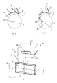
- the figure 8 presents a third embodiment of a driving device 1 according to the invention.
- the introduction ramp 5 (fine line for a remote position, and thick line for a close position) is moved by position adjustment means 11, for example a rack.
- the peripheral ramp 7 (fine line for a remote position, and thick line for a close position) is driven in motion by the movement of the introduction ramp.
- the guide means 12 may consist of a pipe receiving a pin secured to the peripheral ramp 7.
- the figure 9 presents a fourth embodiment of a driving device 1 according to the invention.
- the peripheral ramp 7 (thin line for a remote position, and thick line for a close position) is moved by position adjustment means 11, for example an axis (shown in two positions respectively in solid lines and dotted lines) in rotation around a fixed point 13 and to which is fixed the peripheral ramp 7.
- the introduction ramp 5 (fine line for a remote position, and thick line for a close position) is driven in motion by the movement of the introduction ramp.
- the guide means 12 may consist of a pipe receiving a pin secured to the peripheral ramp 7.
- the introduction ramp 5 is connected to position adjustment means 11 consisting of a rack.
- the angle between the introduction ramp 5 and a rod 14 of the rack is between 20 ° and 60 °, for example 45 °.
- the rod 14 of the rack is connected to the carousel end 3 of the introduction ramp 5.
- the rack is located outside the carousel 3.
- the rod 14 is located between the introduction ramp 5 and the peripheral ramp 7.
- the rod 14 of the rack can be moved by turning a dial 15.
- the adjustment knob 15 can be turned by hand between different predetermined positions, preferably defined by notches.
- the adjustment knob 15 is integral with a pinion which meshes with the rod 14.
- a locking system makes it possible to hold the adjustment wheel in position 15. The locking of the rotation of the wheel of adjusting by pressure on the top of the adjustment knob 15, or by pulling it towards you.
- the angle of rotation between two notches of the adjusting wheel 15 corresponds to 3mm of displacement of the rod 14.
- the peripheral ramp 7 is secured to a support 16.
- the support 16 furthermore has a second peripheral ramp 7 'above the plane formed by the introduction ramp 5 and the peripheral ramp 7.
- the support 16 has an elongate shape in a direction substantially perpendicular to a radius of the carousel 3.
- the support 16 has an elongated shape in a direction substantially tangential to the carousel 3.
- the support 16 has an elongated shape in a direction substantially perpendicular to the introduction ramp 5.
- the support 16 is connected to the introduction ramp 5 by a pivot connection 8.
- the angle between the longitudinal axis of the introduction ramp 5 and the longitudinal axis of the peripheral ramp 7 may therefore vary.
- the support 16 is made of bronze.
- the pivot connection 8 is located on the carousel side 3, for the introduction ramp 5, and on the entry ramp side 5, for the peripheral ramp 7.
- the guide means comprise a connecting piece 17.
- the peripheral ramp slides relative to the connecting piece 17.
- the connecting piece 17 is guided in translation along a radius of the carousel 3.
- a ramp 107 is fixed to the connecting piece 17.
- the connecting piece 17 is guided in translation by being connected to a bar 19 sliding through two rings aligned along the desired axis of translation.
- the bar 19 is perpendicular to the longitudinal direction of the connecting piece 17.
- the connecting piece 17 comprises compensation means 18 consisting of an opening or light.
- the opening 18 has an elongate shape.
- the opening 18 has a bean form.
- the shape of the opening 18 allows that the angle formed between the longitudinal axis of the peripheral ramp 7 and the longitudinal axis of the introduction ramp 5 may vary.
- the opening 18 is in the form of a circular arc centered on the axis of rotation 9 of the carousel 3.
- the support 16 comprises two rods 21 which pass through the opening 18.
- the two rods 21 can be translated into the opening 18.
- the two rods 21 slide in the opening 18.
- the two rods 21 are distant from each other.
- the two rods 21 are not translated along the vertical axis 22.
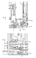
- the Figures 4 and 5 show two views of the driving device 1 according to the invention, in two different positions.
- the figure 4 corresponds to a "forward" position of the driving device 1 according to the invention.
- the figure 5 corresponds to a position "set back" of the driving device 1 according to the invention.
- the setting does not require any tools.
- Fine adjustment can be made to finely adjust the positions of the introduction ramps 5 and peripheral 7 with respect to a given installation 2 and a given type of article 10.
- the invention also relates to a safety device 100, represented in particular to Figures 6 and 7 .
- the safety device 100 makes it possible to detect a bad positioning of an article in the carousel 3 and at the entrance of this carousel 3.
- the safety device 100 comprises means for allowing a deflection of the peripheral ramp 7 under the effect of a request from at least one article disposed in a defective position.
- the peripheral ramp 7 is positioned at such a distance from the periphery of the carousel 3 that the article 10 badly engaged in the peripheral housing exerts a force on the peripheral ramp.
- the peripheral ramp 7 is deflected under the effect of this force.
- Detection means 23 detect the deviation of the peripheral ramp 7 and trigger a safety signal when the measured deviation exceeds a predetermined threshold, for example for a non-zero deviation.
- the safety signal stops the operation of the installation 2.
- the shutdown of the installation 2 is instantaneous.
- the detection means 23 consist of pneumatic detection means.
- One example is a commercial emergency stop module marketed by the company Destaco ®.
- the safety device 100 according to the invention is arranged as a rigid pendulum.
- the detection means 23 are on a fixed point of the pendulum, in height.
- the detection means 23 comprise a fixed cavity having an opening 26.
- the peripheral ramp 7 is rigidly connected to the respective first ends of two columns 24. (It is possible to provide a single column 24. Preferably, at least two columns 24 are provided.)
- the height of the peripheral ramp 7 can be adjusted along the columns 24.
- the columns 24 are connected at their other respective ends to the detection means 23.
- the plate 27 is integral with the peripheral ramp 7, in particular via the columns 24.
- Means for allowing a deviation of the rigid assembly under the effect of a solicitation by at least one article disposed in a defective position are constituted by the plate 27 which is movable in the cavity 25. If the plate 27 could not move in the cavity 25 itself fixed, there would be no deviation of the rigid assembly (here formed in particularly by the peripheral ramp).
- the pressure in the cavity 25 is regulated by a flow of compressed air.
- a flow sensor at the outlet of the source of compressed air makes it possible to detect an increase in the compressed air flow generated by a leak in the cavity 25.
- the plate 27 can be held in place both under the effect of gravity and under the effect of springs in the cavity 25.
- a deflection of the peripheral ramp 7 causes a deflection of the plate 27.
- the deflection of the plate 27 causes a pressure leakage through the opening 26.
- the security device 100 is multidirectional.
- This couple causes a pressure leak through the opening 26, in the cavity 25, which is detected by the detection means 23.
- the plate 27 carries in particular the peripheral ramp 7.
- the sensitivity of the safety device 100 can be adjusted by adjusting the pressure inside the cavity 25.
- This embodiment is shown in particular in the figure 6 .
- the introduction ramp 5 is positioned at such a distance from the worm 6 that the incorrectly engaged article 10 exerts a force on the introduction ramp 5.
- the introduction ramp 5 is connected rigidly to the respective first ends of the two columns 24.
- the height of the introduction ramp 5 can be adjusted along the columns 24.
- the columns 24 are connected at their other respective ends to the plate 27 of the detection means 23.
- any movement of the introduction ramp 5 induces a loss of pressure within the cavity 25 having an opening 26.
- peripheral ramp 7 and the introduction ramp 5 are part of the same rigid assembly (when the adjustment means 11 are in a locked position).
- This rigid assembly is connected to unique detection means 23.
- this rigid assembly comprises the peripheral ramp 7 rigidly connected to the respective first ends of the two columns 24, and the introduction ramp rigidly connected to the respective first ends of the two columns 24.
- the two columns 24 are connected at their other respective ends to the single detection means 23.
- the plate 27 carries the entire rigid assembly.
- the plate 27 can be moved under the effect of a deflection of the peripheral ramp 7.
- the plate 27 can be moved under the effect of a deflection of the introduction ramp 5.
Landscapes
- Engineering & Computer Science (AREA)
- Mechanical Engineering (AREA)
- Specific Conveyance Elements (AREA)
- Transmission Devices (AREA)
Applications Claiming Priority (1)
| Application Number | Priority Date | Filing Date | Title |
|---|---|---|---|
| FR1057824A FR2965255B1 (fr) | 2010-09-28 | 2010-09-28 | Dispositif de conduite d'articles a l'entree d'un carrousel rotatif. |
Publications (1)
| Publication Number | Publication Date |
|---|---|
| EP2433885A1 true EP2433885A1 (de) | 2012-03-28 |
Family
ID=44009965
Family Applications (1)
| Application Number | Title | Priority Date | Filing Date |
|---|---|---|---|
| EP11182996A Withdrawn EP2433885A1 (de) | 2010-09-28 | 2011-09-27 | Vorrichtung zur Führung von Artikeln an dem Eingang eines Sternrads |
Country Status (2)
| Country | Link |
|---|---|
| EP (1) | EP2433885A1 (de) |
| FR (1) | FR2965255B1 (de) |
Cited By (1)
| Publication number | Priority date | Publication date | Assignee | Title |
|---|---|---|---|---|
| CN118458282A (zh) * | 2024-07-09 | 2024-08-09 | 昆山来运机械设备有限公司 | 一种汽车制动盘输送设备及其输送工艺 |
Citations (3)
| Publication number | Priority date | Publication date | Assignee | Title |
|---|---|---|---|---|
| FR1459406A (fr) * | 1965-11-02 | 1966-04-29 | Emhart Zuerich Sa | Appareil servant à déplacer en les faisant rouler des objets qui présentent, au moins approximativement, la forme de solides ronds de révolution |
| CH431377A (de) * | 1965-04-13 | 1967-02-28 | Emhart Zuerich Sa | Einrichtung mit einem Sternrad, zum taktweisen Fördern von Körpern |
| FR2936869A1 (fr) * | 2008-10-06 | 2010-04-09 | Ermi 77 | Installation de controle de la qualite d'une succession d'articles, en particulier des bouteilles. |
-
2010
- 2010-09-28 FR FR1057824A patent/FR2965255B1/fr not_active Expired - Fee Related
-
2011
- 2011-09-27 EP EP11182996A patent/EP2433885A1/de not_active Withdrawn
Patent Citations (3)
| Publication number | Priority date | Publication date | Assignee | Title |
|---|---|---|---|---|
| CH431377A (de) * | 1965-04-13 | 1967-02-28 | Emhart Zuerich Sa | Einrichtung mit einem Sternrad, zum taktweisen Fördern von Körpern |
| FR1459406A (fr) * | 1965-11-02 | 1966-04-29 | Emhart Zuerich Sa | Appareil servant à déplacer en les faisant rouler des objets qui présentent, au moins approximativement, la forme de solides ronds de révolution |
| FR2936869A1 (fr) * | 2008-10-06 | 2010-04-09 | Ermi 77 | Installation de controle de la qualite d'une succession d'articles, en particulier des bouteilles. |
Cited By (1)
| Publication number | Priority date | Publication date | Assignee | Title |
|---|---|---|---|---|
| CN118458282A (zh) * | 2024-07-09 | 2024-08-09 | 昆山来运机械设备有限公司 | 一种汽车制动盘输送设备及其输送工艺 |
Also Published As
| Publication number | Publication date |
|---|---|
| FR2965255A1 (fr) | 2012-03-30 |
| FR2965255B1 (fr) | 2012-10-26 |
Similar Documents
| Publication | Publication Date | Title |
|---|---|---|
| EP1350748B1 (de) | Vorrichtung zum Wenden von Stapeln von Bogenmaterial | |
| EP3049789B1 (de) | Stütze und drehvorrichtung zur visuellen prüfung eines reifens und zugehöriges verfahren | |
| EP3822199B1 (de) | Stern für eine rotierende verpackungsmaschine | |
| EP3994012B1 (de) | Umwandelbares rad zum überqueren jeglicher art von gelände und autonomer roboter mit mindestens einem solchen rad | |
| EP3230185B1 (de) | Vorrichtung zur herstellung eines behälters mit zwei rollen zur ansteuerung eines behälters | |
| EP3365663B1 (de) | Verfahren und vorrichtung zur optischen inspektion des profils von behältern, wobei das profil den boden umfasst | |
| FR2965255A1 (fr) | Dispositif de conduite d'articles a l'entree d'un carrousel rotatif. | |
| EP0320376A1 (de) | Vorrichtung zum Überziehen eines Gegenstands, wie eine Kanne, mit einem hülsenförmigen Etikett | |
| WO2002055290A1 (fr) | Tambour de conformation pour la fabrication de pneumatiques | |
| EP2433884A1 (de) | Sicherheitsvorrichtung zum Entdecken einer schlechten Positionierung eines Artikels am Eingang eines Verteilerbandes | |
| EP2896584B1 (de) | Qualitätskontrollanlage einer Reihe von Artikeln, insbesondere von Flaschen | |
| EP2684822B1 (de) | Vorrichtung zum Vergrössern eines Schritts für eine positive und individuelle Übertragung von Objekten | |
| EP2772457A1 (de) | Hilfsanlage zur Verpackung von Artikeln | |
| EP1775126A2 (de) | Übertragungsvorrichtung von Gegenständen für eine Druckmaschine, Druckmaschine und Übertragungsverfahren | |
| CA2473111C (fr) | Support pour elements cylindriques en defilement et procede et transporteur utilisant de tels supports. | |
| WO2020152417A1 (fr) | Procede et dispositif de convoyage de recipients en position suspendue | |
| EP1476321B1 (de) | Vorrichtung zum montieren eines reifens an einer fahrzeugfelge | |
| EP3114055B1 (de) | Verfahren und anlage zum ausgerichteten zuführen von zuschnitten | |
| FR2937280A1 (fr) | Machine de traitement de documents a entrainement ameliore. | |
| FR2950040A1 (fr) | Installation adaptable de transfert de flacons. | |
| EP4366957B1 (de) | Pistole zum ausstossen einer speiche in ein loch in einer nabe eines speichenrads | |
| FR2705605A1 (fr) | Dispositif de démontage d'une porte de véhicule automobile, par soulèvement axial à l'aide d'un robot. | |
| EP2335020A1 (de) | Installation zur prüfung der qualität einer abfolge von artikeln, insbesondere flaschen | |
| CH482610A (fr) | Procédé et dispositif de transport pneumatique de pièces | |
| EP2892796A1 (de) | Ausrichtbare befestigung eines elastisches gelenks auf einem aufhängungsarm eines kraftfahrzeugs |
Legal Events
| Date | Code | Title | Description |
|---|---|---|---|
| PUAI | Public reference made under article 153(3) epc to a published international application that has entered the european phase |
Free format text: ORIGINAL CODE: 0009012 |
|
| AK | Designated contracting states |
Kind code of ref document: A1 Designated state(s): AL AT BE BG CH CY CZ DE DK EE ES FI FR GB GR HR HU IE IS IT LI LT LU LV MC MK MT NL NO PL PT RO RS SE SI SK SM TR |
|
| AX | Request for extension of the european patent |
Extension state: BA ME |
|
| STAA | Information on the status of an ep patent application or granted ep patent |
Free format text: STATUS: THE APPLICATION IS DEEMED TO BE WITHDRAWN |
|
| 18D | Application deemed to be withdrawn |
Effective date: 20120929 |