EP2434202A1 - Lampe d'opération dotée d'un dispositif de commande stérile - Google Patents
Lampe d'opération dotée d'un dispositif de commande stérile Download PDFInfo
- Publication number
- EP2434202A1 EP2434202A1 EP10181051A EP10181051A EP2434202A1 EP 2434202 A1 EP2434202 A1 EP 2434202A1 EP 10181051 A EP10181051 A EP 10181051A EP 10181051 A EP10181051 A EP 10181051A EP 2434202 A1 EP2434202 A1 EP 2434202A1
- Authority
- EP
- European Patent Office
- Prior art keywords
- operating
- light
- operating device
- focusing
- movement
- Prior art date
- Legal status (The legal status is an assumption and is not a legal conclusion. Google has not performed a legal analysis and makes no representation as to the accuracy of the status listed.)
- Granted
Links
Images



Classifications
-
- A—HUMAN NECESSITIES
- A61—MEDICAL OR VETERINARY SCIENCE; HYGIENE
- A61B—DIAGNOSIS; SURGERY; IDENTIFICATION
- A61B90/00—Instruments, implements or accessories specially adapted for surgery or diagnosis and not covered by any of the groups A61B1/00 - A61B50/00, e.g. for luxation treatment or for protecting wound edges
- A61B90/30—Devices for illuminating a surgical field, the devices having an interrelation with other surgical devices or with a surgical procedure
-
- F—MECHANICAL ENGINEERING; LIGHTING; HEATING; WEAPONS; BLASTING
- F21—LIGHTING
- F21V—FUNCTIONAL FEATURES OR DETAILS OF LIGHTING DEVICES OR SYSTEMS THEREOF; STRUCTURAL COMBINATIONS OF LIGHTING DEVICES WITH OTHER ARTICLES, NOT OTHERWISE PROVIDED FOR
- F21V21/00—Supporting, suspending, or attaching arrangements for lighting devices; Hand grips
- F21V21/40—Hand grips
- F21V21/403—Hand grips for operation or dentist lamps
-
- F—MECHANICAL ENGINEERING; LIGHTING; HEATING; WEAPONS; BLASTING
- F21—LIGHTING
- F21V—FUNCTIONAL FEATURES OR DETAILS OF LIGHTING DEVICES OR SYSTEMS THEREOF; STRUCTURAL COMBINATIONS OF LIGHTING DEVICES WITH OTHER ARTICLES, NOT OTHERWISE PROVIDED FOR
- F21V23/00—Arrangement of electric circuit elements in or on lighting devices
- F21V23/04—Arrangement of electric circuit elements in or on lighting devices the elements being switches
- F21V23/0442—Arrangement of electric circuit elements in or on lighting devices the elements being switches activated by means of a sensor, e.g. motion or photodetectors
-
- H—ELECTRICITY
- H05—ELECTRIC TECHNIQUES NOT OTHERWISE PROVIDED FOR
- H05B—ELECTRIC HEATING; ELECTRIC LIGHT SOURCES NOT OTHERWISE PROVIDED FOR; CIRCUIT ARRANGEMENTS FOR ELECTRIC LIGHT SOURCES, IN GENERAL
- H05B47/00—Circuit arrangements for operating light sources in general, i.e. where the type of light source is not relevant
- H05B47/10—Controlling the light source
- H05B47/105—Controlling the light source in response to determined parameters
- H05B47/115—Controlling the light source in response to determined parameters by determining the presence or movement of objects or living beings
-
- A—HUMAN NECESSITIES
- A61—MEDICAL OR VETERINARY SCIENCE; HYGIENE
- A61B—DIAGNOSIS; SURGERY; IDENTIFICATION
- A61B90/00—Instruments, implements or accessories specially adapted for surgery or diagnosis and not covered by any of the groups A61B1/00 - A61B50/00, e.g. for luxation treatment or for protecting wound edges
- A61B90/30—Devices for illuminating a surgical field, the devices having an interrelation with other surgical devices or with a surgical procedure
- A61B2090/308—Lamp handles
-
- F—MECHANICAL ENGINEERING; LIGHTING; HEATING; WEAPONS; BLASTING
- F21—LIGHTING
- F21W—INDEXING SCHEME ASSOCIATED WITH SUBCLASSES F21K, F21L, F21S and F21V, RELATING TO USES OR APPLICATIONS OF LIGHTING DEVICES OR SYSTEMS
- F21W2131/00—Use or application of lighting devices or systems not provided for in codes F21W2102/00-F21W2121/00
- F21W2131/20—Lighting for medical use
- F21W2131/205—Lighting for medical use for operating theatres
-
- Y—GENERAL TAGGING OF NEW TECHNOLOGICAL DEVELOPMENTS; GENERAL TAGGING OF CROSS-SECTIONAL TECHNOLOGIES SPANNING OVER SEVERAL SECTIONS OF THE IPC; TECHNICAL SUBJECTS COVERED BY FORMER USPC CROSS-REFERENCE ART COLLECTIONS [XRACs] AND DIGESTS
- Y02—TECHNOLOGIES OR APPLICATIONS FOR MITIGATION OR ADAPTATION AGAINST CLIMATE CHANGE
- Y02B—CLIMATE CHANGE MITIGATION TECHNOLOGIES RELATED TO BUILDINGS, e.g. HOUSING, HOUSE APPLIANCES OR RELATED END-USER APPLICATIONS
- Y02B20/00—Energy efficient lighting technologies, e.g. halogen lamps or gas discharge lamps
- Y02B20/40—Control techniques providing energy savings, e.g. smart controller or presence detection
Definitions
- the invention relates to a surgical light with a sterile control device whose functions can be operated sterile by a surgeon.
- a good illumination of the surgical field is required. This can usually be accomplished by adjusting various parameters of the surgical light. For this purpose, usually a position and orientation of the lamp body, a focusing of the light beams on the surgical site and an intensity of the radiated light beams, so the brightness of the illumination of the surgical site, adjustable.
- a change in position and orientation is usually performed by the surgeon himself, which takes the lamp body to a sterile handle, which is pushed over a handle receptacle of the lamp body, and pivots to the desired position and in the desired orientation.
- By turning the sterile handle is then usually the focusing of the light rays, that is set the distance of the intersection of the radiated light beams from the lamp body.
- Adjustment of the brightness is normally carried out by means of non-sterilized controls on the edge of the lamp body, on the support system, or on a wall control unit not by the surgeon, but by surgical staff, where lower sterility requirements exist. But this additional staff is required and a desired adjustment of the brightness is complicated by the necessary communication between the surgeon and personnel, which can be dangerous especially in critical operating situations for the patient.
- a sterilizable control element which is mounted in addition to the sterilizable handle on the lamp body, whereby also other functions, such as setting a color temperature, setting a light distribution or operating a camera, can be operated sterile.
- this requires a further control element, and the ability to make adjustments in multiple modes of operation may require the operator to first select the desired mode of operation.
- this adjustment in a surgical light that has only the functions brightness and focus adjustable, consuming and distracts the surgeon.
- the problem is also that when adjusting the orientation of the operating light by the surgeon when the lamp body is rotated about its axis, this rotation is done on the sterile handle, and thereby the focus of the light beams is changed.
- a lamp body is designed so that it has an operating device that can be operated without contact.
- Non-contact in this context means that although the operating device itself, in particular a sensor of the operating device, is not touched, sterile components of the lamp body, which cover the sensor of the operating device, can however be touched.
- Fig. 1 shows a perspective view of a surgical lamp 1, which has a lamp body 2.
- the lamp body 2 is connected via a suspension device 4, of which only a lower portion is shown, with a ceiling, not shown, a mobile tripod, or the like connected.
- the suspension device 4 represents a gimbal, so that the lamp body 2 can be positioned within a certain radius of action in any position and in any orientation.
- the luminaire body 2 has four edge modules 9 and a central module 10, the edge modules 9 being mounted pivotably on the central module 10.
- the operating light 1 may be provided as a dissolved light system with individual lights instead of modules as well as be designed as a large mirror light.
- pivotable modules or pivotable headlights can be provided within a housing of a lamp body.
- the edge modules 9 and the central module 10 each have a plurality of light sources 3, which are each formed in this embodiment as an LED with a lens.
- the light sources 3 each emit a light beam.
- the individual headlamps of the dissolved light system each have a light source, and a large mirror light has a single operated light source in the lamp body.
- the lamp body 2 is provided in this embodiment with a handle receptacle 6, which projects on the underside of the central module 10 at a light exit surface.
- the handle holder 6 may be provided in alternative embodiments also at a different location on the lamp body 2 or on the suspension device 4.
- the operation lamp 1 further comprises a focusing device 5 and a dimming device 8, which are housed in this embodiment in a housing of the lamp body 2, but need not necessarily be here, but may also be provided at a suitable location of the operating light 1.
- the function of the focusing device 5 and the dimming device 8 will be explained below.
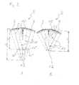
- Fig. 2 shows the lamp body 2 in two different focus settings.
- the edge modules 9 and the central module 10 each emit a light beam 11 from the lamp body 2, which is generated by the individual light sources 3, the light beams 11 themselves being adapted so that each individual module is a light field, ie an illuminated area on the surgical site of a patient.
- a suitable focusing of the light bundles of the modules ie when the angular position between the respective edge module 9 and the central module 10 is selected so that the individual light fields on the surgical site come to cover, a common light field 12 is formed on the surgical site.
- the light bundles 11 each have a central axis 22, which intersect in the formation of the common light field 12 on the illuminated area on the surgical site.
- the central axes 22 of the light beams 11 intersect at a distance l 1 from the lamp body 2.
- the image of the light beams 11 on the surgical site is identical and the common light field 12 is formed.
- the light beams 11 each on light panels 12 ', 12'',12''' shown, which are not identical, but only partially overlap.
- the edge modules 9 are pivoted to the center module 10 so that the central axes 22 of the light beams 11 again intersect at the surgical site at a distance l 2 , so that the light beams are imaged on the operating field in the common light field 12 , and thus optimally illuminate the surgical field.
- the edge modules 9 are pivoted by a drive, not shown.
- the drive is controlled by the focussing device 5 (FIG. Fig. 1 ) according to an input of an operator.
- An adjustment of the angle of the edge modules 9 to the central module 10 is infinitely possible between two end positions. All edge modules 9 are adjusted simultaneously, so that the intersection of the central axes 22 of the light beam 11 is located in each case on the central axis 22 of the light beam 11 of the central module 10 and each have a different distance to the lamp body 2.
- Fig. 3 shows the handle receptacle 6 with a arranged around the handle receptacle 6 handle 14.
- the handle receptacle 6 has an operating device 7, which in turn has an operating film 17.
- the handle receptacle 6 is provided in the axial direction over a certain length with a circumferential recess.
- the operating film 17 is inserted, whose length in the axial direction of the handle receptacle 6 approximately corresponds to the axial length of the recess, but is slightly shorter, and which has a width which corresponds approximately to the circumference of the recess in the handle receptacle 6 , so that the entire circumference of the depression is covered with the operating film 17.
- a protective cover 13 is slipped from a rubber material. The ends of the protective cover 13 in the axial direction each form an inwardly facing collar, so that in the axially extending space between the collar, the operating film 17 can be accommodated.
- the operating film 17 is protected from moisture and mechanical damage.
- the handle holder 6 is attached to the lamp body 2 ( Fig. 1 ). To the handle holder 6, the handle 14 is pushed and fixed axially and radially with a locking element, not shown.
- the handle 14 is made of a sterilizable material so as to meet the hygienic requirements for a sterile actuator.
- the handle may also be designed as a disposable handle in the form of a sterile elastic plastic cover.
- an evaluation unit 25 of the operating device 7, and a laser sensor 26 are arranged for distance measurement. These components may be in alternative embodiments be arranged at other locations of the lamp body 2 or the operating light 1.
- this has a transparent cover 15 as a diffusing screen and a lighting means 16 as a display means.
- the illuminant 16 indicates adjustment situations of the operation lamp 1.
- the transparent cover 15 is made circumferentially of a transparent material so that the display of the illuminant 16 can be perceived from any direction around the operation light.
- Fig. 4 shows the operating film 17 of the operating device 7.
- the operating film 17 has, as already in the description Fig. 3 explained, a width which corresponds approximately to the circumference of the recess of the handle receptacle 6. Since the handle holder 6 is not cylindrical, but slightly conical, and the width of the operating film 17 is slightly tapered down.
- the operating film 17 consists of a carrier film 18, are applied to the copper tracks 19.
- the copper tracks 19 are shown on the operating foil 17, three arrangements each extending in the vertical direction and each forming a vertical sensor 23, and an arrangement extending in the horizontal direction at the upper end of the operating foil 17 and forming a horizontal sensor 24 ,
- the copper tracks 19 are each connected via conductor tracks 20 to a connector 21.
- the operating film 17 is connected to the evaluation unit 25 of the operating device 7.
- the evaluation unit 25 can either be designed as a separate unit, or alternatively be integrated in a control device of the operating light 1.
- the horizontal sensor 24 When installed, the horizontal sensor 24 thus forms a sensor area surrounding the handle receptacle 6.
- the vertical sensors 23 each form a sensor surface in the axial direction of the handle receptacle 6, which are seen in the axial direction of the handle receptacle 6, arranged at an angular distance of about 120 °.
- the copper tracks 19 form by their shape and arrangement to each other capacitive sensors.
- other controls that are non-contact operable e.g. optical controls, are used.
- the operation lamp 1 is configured so that the horizontal sensor 24 is used for dimming the light sources 3 of the operation lamp 1, and the three vertical sensors 23 are used for focusing the operation lamp 1 by the sensors 23, 24 each by a predetermined movement an operator be operated without contact.
- the operating device 7 is configured such that, in order to control the dimming, ie an illumination intensity change, the horizontal sensor 24 detects in a first step of a dimming process, if an object, eg a finger or a part of a surgical instrument, in the region of the horizontal sensor 24th is brought. As a result, the horizontal sensor 24 outputs a corresponding signal to the evaluation unit 25, as a result of which the operating device 7 detects the introduction of the object into the region of the horizontal sensor 24.
- the horizontal sensor 24 By moving the object along the circumference of the handle mount 6 or mounted Handle 14, ie along the horizontal sensor 24, detects the horizontal sensor 24, in which position the object is due to the movement relative to the originally detected position, and transmits corresponding signals to the evaluation unit 25.
- the operating device 7 is configured so that its evaluation unit 25 detects in a second step, in which direction the object is moved, namely clockwise or counterclockwise with respect to the axis of the handle receptacle 6, and in a third step detects by which distance the object is moved.
- the operating device 7 is further configured such that its evaluation unit 25 outputs in a fourth step respective signals corresponding to the direction of movement and the distance of the movement to the dimming device 8.
- a direction of movement in a clockwise direction with respect to the axial direction of the handle receptacle 6 here corresponds to an increase in the brightness of the operating light 1
- a counterclockwise movement here corresponds to a reduction in brightness. This assignment can also be reversed in other embodiments.
- the evaluation unit 25 is configured so that a distance of the object of 1 cm along the horizontal sensor 24 corresponds to the change of one brightness level.
- the illumination intensity change per brightness level is defined in the dimming device 8.
- the assignment of the distance to a brightness level may also correspond to another value, or be stepless.
- the operating device 7 is configured to detect activation of the focusing, one or more of the vertical sensors 23 in a first step of a focusing method, when an object, eg a finger or a part of a Surgical set, is placed in the range of one of the vertical sensors 23 /, and outputs a corresponding signal to the evaluation unit 25, whereby the operating device 7 detects the introduction of the object in the region of the vertical sensors 23.
- an object eg a finger or a part of a Surgical set
- the vertical sensors 23 transmit signals to the evaluation unit 25 in which position the object is due to the movement relative to the originally detected position , and the operating device 7 is configured so that it detects in a second step, in which direction, namely towards the lamp body 2 or away from the lamp body 2, the object is moved.
- a signal to the focusing device 5 the edge modules 9 merge, ie the distance of the point in which the axes 22 of the light beam 11 are focused to reduce the lamp body 2.
- a movement of the object in the direction of the lamp body 2 results in a third step, the output of a signal of the operating device 7 to the focusing device 5 to move apart of the modules, ie the distance between the intersection of the axes 22 of the light beam 11 to the lamp body 2 is increased ,
- the signal is output as long as the evaluation unit 25 detects the presence of the object during or after the movement in the region of one of the vertical sensors 23 in a fourth step until the object is removed from the sensor surface.
- a signal is given to the focusing device 5 to change the distance between the intersection of the axes 22 and the lamp body 2 in the opposite direction until the object is removed from the sensor surface.
- the surgical light 1 is by default in an automatic mode in which the distance between the lamp body 2 and the surgical site is measured by a distance measurement with the aid of the laser sensor 26.
- the optimal light field 12 is adjusted by the focusing device 5.
- the surgeon can always correct the automatic by operating the operating device 7.
- the last set distance may be maintained or a default predetermined value (for example, the standard value of one meter) may be set.
- the operating device 7 is connected to the control device of the operating light 1, which in turn is connected to the focusing device 5 and the dimming device 8 and this drives. In alternative embodiments, the operating device 7 is connected directly to the focusing device 5 and the dimming device 8.
- the association between the sensors 23, 24 and the dimming and focusing functions may also be determined in other ways in other embodiments.
- the way of detecting the motion sequence namely on the one hand the detection of the direction and the distance of a movement, and on the other hand, the detection of the direction of movement and the duration of the presence of the object, not assigned to a specific sensor or function, but the assignment can be done in any suitable manner.
- the control of other functions such as a color temperature setting is possible.
- the operator can either operate the corresponding function of the operation light 1 without actually touching the operation light 1, or he drives the object along a sterilizable cover, in this embodiment, the sterile handle 14, both the sterile operation the operating light 1 allows.
- a sensitivity of the capacitive sensors by means for adjusting adjustable or programmable.
- a calibration device is provided, which automatically calibrates the operating device 7 during switch-on by detecting which input values are present in the evaluation unit 25 when switching on. These values are set as the limits of a "non-actuation" so that the approach and movement of an object (eg the finger) is detected.
- a control of the focusing or dimming even without control handle or with any operating handle (tolerance compensation), or with eg the elastic plastic coating performed.
- the recorded values are cyclically checked during operation to determine whether there are any longer lasting changes in the values. As a result, for example, a sliding and mounting of a handle 14 is detected, which was not yet mounted when switching on the operating light 1, and the values are adjusted so that a recognition eg of a finger takes place despite the deferred handle 14.
- Repositioning of the lamp body 2 of the operation lamp 1 is detected by an acceleration sensor, not shown, provided in the lamp body 2 and connected to the control device of the operation lamp 1.
- the operating device 7 is configured in such a way that, when it is repositioned, it is directly controlled via a control device of the operating light 1 or alternatively by the acceleration sensor not to react to the signals of the vertical sensors 23 and / or the horizontal sensor 24, so that no signals are emitted the focusing device 5 and / or the dimming device 8 are passed.
- Focussing of the light bundles 11 or dimming of the brightness begins only if, after the detection of an object on the handle receptacle 6, a movement of the object is also detected, and a certain path, e.g. 1 cm, is covered. Only a mere presence of an object, e.g. the gripping of the handle 14 for repositioning is not recognized as an operation for changing the focus or for dimming.
- the lighting means 16 is used to indicate a change of settings of the operation light 1.
- the lighting means 16 is operated in a basic brightness at a medium brightness.
- changing one of the adjustable settings of the operating light 1, for example dimming or focusing this is indicated by changing the brightness of the indicator light means 16.
- the dimming device 8 By controlling the dimming device 8 for increasing the luminance of the operation lamp 1, the brightness of the display lamp is also increased.
- a change in the focus is displayed by the brightness of the display light means 16 is increased in a collapse of the edge modules 9.
- a reduction of the luminosity of the indicator light means 16 takes place in each case by reverse control, ie reducing the luminosity of the operating light 1, or when driving apart of the edge modules 9.
- the indicator light means 16 by a control unit, with the it is again set to the basic brightness, and if a setting is subsequently changed, it is again displayed relative to the change.
- the light-emitting means 16 is designed in the form of an LED. Also alternatively, a scale consisting of several LEDs is possible. Furthermore, it is alternatively possible to activate the display according to the currently changed function of the operating light 1 and display the current setting. Alternatively, the display of a setting, e.g. Focusing, permanently possible. In addition, an acoustic feedback is conceivable.
- the number of sensors 23, 24 depends on the number of functions to be set. For an ergonomic operation of the operating light and a plurality of sensors 23, 24 may be provided for a function at different locations of the operating light, or a sensor at a desired location of the surgical light. In either case, however, the sensors are replaced by a sterilizable cover, e.g. the handle 14, which covers the sensor, driven through.
Landscapes
- Engineering & Computer Science (AREA)
- Health & Medical Sciences (AREA)
- General Engineering & Computer Science (AREA)
- Surgery (AREA)
- Life Sciences & Earth Sciences (AREA)
- Biomedical Technology (AREA)
- Pathology (AREA)
- Oral & Maxillofacial Surgery (AREA)
- Nuclear Medicine, Radiotherapy & Molecular Imaging (AREA)
- Heart & Thoracic Surgery (AREA)
- Medical Informatics (AREA)
- Molecular Biology (AREA)
- Animal Behavior & Ethology (AREA)
- General Health & Medical Sciences (AREA)
- Public Health (AREA)
- Veterinary Medicine (AREA)
- Non-Portable Lighting Devices Or Systems Thereof (AREA)
- Surgical Instruments (AREA)
Priority Applications (6)
| Application Number | Priority Date | Filing Date | Title |
|---|---|---|---|
| ES10181051.3T ES2612915T3 (es) | 2010-09-28 | 2010-09-28 | Lámpara quirúrgica con un dispositivo de mando estéril |
| EP10181051.3A EP2434202B2 (fr) | 2010-09-28 | 2010-09-28 | Lampe d'opération dotée d'un dispositif de commande stérile |
| PL10181051T PL2434202T3 (pl) | 2010-09-28 | 2010-09-28 | Lampa operacyjna ze sterylnym zespołem obsługowym |
| DK10181051.3T DK2434202T3 (en) | 2010-09-28 | 2010-09-28 | Operating lamp with sterile control device |
| US13/246,006 US8833953B2 (en) | 2010-09-28 | 2011-09-27 | Surgical lamps and related systems and methods |
| CN201110334661.4A CN102537796B (zh) | 2010-09-28 | 2011-09-28 | 具有无菌操作装置的外科手术灯具 |
Applications Claiming Priority (1)
| Application Number | Priority Date | Filing Date | Title |
|---|---|---|---|
| EP10181051.3A EP2434202B2 (fr) | 2010-09-28 | 2010-09-28 | Lampe d'opération dotée d'un dispositif de commande stérile |
Publications (3)
| Publication Number | Publication Date |
|---|---|
| EP2434202A1 true EP2434202A1 (fr) | 2012-03-28 |
| EP2434202B1 EP2434202B1 (fr) | 2016-11-02 |
| EP2434202B2 EP2434202B2 (fr) | 2021-04-21 |
Family
ID=43447701
Family Applications (1)
| Application Number | Title | Priority Date | Filing Date |
|---|---|---|---|
| EP10181051.3A Active EP2434202B2 (fr) | 2010-09-28 | 2010-09-28 | Lampe d'opération dotée d'un dispositif de commande stérile |
Country Status (6)
| Country | Link |
|---|---|
| US (1) | US8833953B2 (fr) |
| EP (1) | EP2434202B2 (fr) |
| CN (1) | CN102537796B (fr) |
| DK (1) | DK2434202T3 (fr) |
| ES (1) | ES2612915T3 (fr) |
| PL (1) | PL2434202T3 (fr) |
Cited By (8)
| Publication number | Priority date | Publication date | Assignee | Title |
|---|---|---|---|---|
| ITMI20122014A1 (it) * | 2012-11-27 | 2014-05-28 | Comm S R L G | Lampada orientabile per ambienti operatori, ambulatori e studi medici o dentistici, e metodo di pilotaggio della stessa |
| DE102013215337A1 (de) | 2013-08-05 | 2015-02-05 | Trilux Medical Gmbh & Co. Kg | OP-Leuchte mit Steuerung |
| DE102014222794A1 (de) * | 2014-11-07 | 2016-05-12 | Trumpf Medizin Systeme Gmbh + Co. Kg | Operationsleuchte und Verfahren zum Betreiben einer Operationsleuchte |
| DE102015113336A1 (de) * | 2015-08-13 | 2017-02-16 | Karl Leibinger Medizintechnik Gmbh & Co. Kg | Handgriffvorrichtung für eine Operationsleuchte mit Sensoren sowie Operationsleuchte |
| WO2017025513A1 (fr) * | 2015-08-13 | 2017-02-16 | Karl Leibinger Medizintechnik Gmbh & Co. Kg | Lampe de salle d'opération avec régulation de luminosité |
| WO2023041732A1 (fr) * | 2021-09-17 | 2023-03-23 | Dr. Mach Gmbh & Co. Kg | Dispositif d'éclairage pour éclairer une plaie chirurgicale |
| CN116347710A (zh) * | 2022-12-26 | 2023-06-27 | 联影(常州)医疗科技有限公司 | 室内灯光的控制方法、系统、设备及介质 |
| US20230248248A1 (en) * | 2022-02-10 | 2023-08-10 | American Sterilizer Company | Patient temperature monitoring system |
Families Citing this family (30)
| Publication number | Priority date | Publication date | Assignee | Title |
|---|---|---|---|---|
| PL2434202T3 (pl) | 2010-09-28 | 2017-07-31 | Trumpf Medizin Systeme Gmbh + Co. Kg | Lampa operacyjna ze sterylnym zespołem obsługowym |
| JP4841013B1 (ja) * | 2011-01-13 | 2011-12-21 | 正一 中村 | 医療用光源装置 |
| USD699879S1 (en) | 2011-08-19 | 2014-02-18 | Trumpf Medizin Systeme Gmbh + Co. Kg | Medical lamp |
| US8789243B2 (en) * | 2012-09-19 | 2014-07-29 | Ecolab Usa Inc. | Disposable handle cover for a surgical lighthead |
| CN103162191A (zh) * | 2013-03-19 | 2013-06-19 | 苏州沃伦韦尔高新技术股份有限公司 | 具有测距反馈照度自动调节功能的手术灯 |
| CN104214602A (zh) * | 2013-05-31 | 2014-12-17 | 北京谊安医疗系统股份有限公司 | 用于无影灯的照明装置及具有其的无影灯 |
| CN103557476B (zh) * | 2013-10-30 | 2015-08-19 | 宋红 | 一种医用无影手术灯 |
| CN103697385A (zh) * | 2014-01-09 | 2014-04-02 | 苏州承腾电子科技有限公司 | 新型led无影灯 |
| CN105805703B (zh) * | 2014-12-31 | 2018-08-31 | 上海正华医疗设备有限公司 | 一种无影灯调光机构 |
| DE102015113337A1 (de) * | 2015-08-13 | 2017-02-16 | Karl Leibinger Medizintechnik Gmbh & Co. Kg | Operationsleuchte mit veränderbarer Lichtfeldgeometrie |
| DE102015113338B4 (de) | 2015-08-13 | 2017-10-05 | Karl Leibinger Medizintechnik Gmbh & Co. Kg | Handgriffvorrichtung für eine Operationsleuchte mit Sprachsteuerung sowie Operationsleuchte |
| KR101697874B1 (ko) * | 2015-10-30 | 2017-01-18 | 동의대학교 산학협력단 | 위치 경로 추적 의시술용 조명 장치 및 이의 제어 방법 |
| USD843635S1 (en) * | 2015-11-12 | 2019-03-19 | Antoinetta Jacoba Hendrika Van Egmond | Solar powered lamp |
| CN105953140A (zh) * | 2016-05-18 | 2016-09-21 | 广东多姆多电子科技有限公司 | 一种红外检测亮度实现照度自动补偿led手术无影灯 |
| CN105910024B (zh) * | 2016-05-18 | 2018-05-22 | 广东多姆多电子科技有限公司 | 一种雷达感应距离实现光斑大小自动调节的手术无影灯 |
| CN106028576A (zh) * | 2016-07-27 | 2016-10-12 | 南通医疗器械有限公司 | 一种能智能调光的免触控led手术无影灯电路控制系统 |
| US10603132B2 (en) | 2016-11-01 | 2020-03-31 | American Sterilizer Company | Lighthead identification system for lighthead control |
| JP2019029322A (ja) * | 2017-08-03 | 2019-02-21 | サムテック・イノベーションズ株式会社 | 医療用無影灯 |
| US10321970B1 (en) | 2018-01-09 | 2019-06-18 | American Sterilizer Company | Handle assembly for a surgical lighting system |
| US10650988B2 (en) | 2018-01-09 | 2020-05-12 | American Sterilizer Company | Sterilizable handle actuating button integration |
| US10772702B2 (en) | 2018-03-13 | 2020-09-15 | American Sterilizer Company | Surgical lighting apparatus including surgical lighthead with moveable lighting modules |
| US20200060785A1 (en) * | 2018-08-21 | 2020-02-27 | Amico Clinical Solutions Corporation | Smart handle for surgical lamp |
| CN111140792B (zh) * | 2018-11-02 | 2023-07-04 | 南京迈瑞生物医疗电子有限公司 | 一种手术灯的调节方法、手术灯、计算机设备和存储介质 |
| CN109512527B (zh) * | 2018-11-02 | 2021-08-27 | 南京迈瑞生物医疗电子有限公司 | 手术室控制系统、方法、计算机设备和存储介质 |
| KR20220022475A (ko) * | 2019-06-20 | 2022-02-25 | 젠텍스 코포레이션 | 객체 추적을 위한 조명 시스템 및 방법 |
| EP4097514B1 (fr) * | 2020-01-31 | 2024-03-20 | American Sterilizer Company | Tête lumineuse à ensemble lentille rotatif et procédé de fonctionnement de celle-ci |
| USD1014832S1 (en) | 2021-09-16 | 2024-02-13 | Trumpf Medizin Systeme Gmbh + Co. Kg | Support arm for a suspension apparatus for a medical lamp |
| USD1015622S1 (en) | 2021-09-16 | 2024-02-20 | Trumpf Medizin Systeme Gmbh + Co. Kg | Suspension apparatus for a medical lamp |
| CN114096045B (zh) * | 2021-12-29 | 2023-12-19 | 海杰亚(北京)医疗器械有限公司 | 一种跟踪手术视野的智能无影灯及其使用方法 |
| US20240196503A1 (en) * | 2022-12-12 | 2024-06-13 | Stryker Corporation | Systems and methods for controlling a medical light via a handle |
Citations (8)
| Publication number | Priority date | Publication date | Assignee | Title |
|---|---|---|---|---|
| FR2557711A1 (fr) * | 1983-12-29 | 1985-07-05 | Bso Steuerungstechnik Gmbh | Manche de commande, en particulier pour telecommande d'appareils entraines hydrauliquement |
| US20030185009A1 (en) * | 2002-03-28 | 2003-10-02 | Walters Mark Wayne | Lighting apparatus with electronic shadow compensation |
| DE20316755U1 (de) * | 2003-10-31 | 2005-03-17 | Leibinger Medizintech | Medizinische Beleuchtungseinrichtung |
| GB2423378A (en) * | 2005-01-28 | 2006-08-23 | Stephen Terry | A lamp |
| EP1750052A1 (fr) | 2005-08-06 | 2007-02-07 | TRUMPF Kreuzer Medizin Systeme GmbH + Co. KG | Lampe scialytique |
| US20080311993A1 (en) * | 2007-06-16 | 2008-12-18 | Rafi Gmbh & Co. Kg | Device for generating control signals that can be evaluated electrically |
| EP2169965A1 (fr) * | 2008-09-30 | 2010-03-31 | TRUMPF Medizin Systeme GmbH + Co. KG | Système doté d'un éclairage d'opération, d'une caméra et d'un moniteur |
| WO2010146446A1 (fr) * | 2009-06-16 | 2010-12-23 | Davide Girlando | Appareil d'éclairage robotisé et procédé de commande |
Family Cites Families (17)
| Publication number | Priority date | Publication date | Assignee | Title |
|---|---|---|---|---|
| US5637863A (en) | 1994-08-24 | 1997-06-10 | Mdt Corporation | Surgical light with touchless switch |
| US20050099824A1 (en) | 2000-08-04 | 2005-05-12 | Color Kinetics, Inc. | Methods and systems for medical lighting |
| DE10251133B3 (de) * | 2002-10-31 | 2004-07-29 | Gerd Reime | Einrichtung zur Steuerung einer Beleuchtung, insbesondere für Fahrzeuginnenräume sowie Verfahren zu ihrer Steuerung |
| ATE357627T1 (de) | 2004-02-28 | 2007-04-15 | Trumpf Kreuzer Med Sys Gmbh | Operationsleuchte |
| EP1568934B1 (fr) | 2004-02-28 | 2012-05-30 | TRUMPF Medizin Systeme GmbH + Co. KG | Lampe chirurgicale |
| EP1568938B1 (fr) | 2004-02-28 | 2006-09-27 | TRUMPF Kreuzer Medizin Systeme GmbH + Co. KG | Lampe chirurgicale et procédé d'illumination d'un champ opératoire |
| DE502005002660D1 (de) | 2005-05-14 | 2008-03-13 | Trumpf Kreuzer Med Sys Gmbh | Operationsleuchte mit zonenweiser Intensitätssteuerung |
| CA2933895C (fr) | 2005-07-14 | 2020-06-09 | Stryker Corporation | Systeme de protection personnelle comprenant un casque, le casque comportant des boutons de commande installes sur une barre de menton |
| DE202007007054U1 (de) | 2006-11-15 | 2007-07-26 | Trumpf Kreuzer Medizin Systeme Gmbh + Co. Kg | System mit einer Operationsleuchte und mit einer Kamera |
| WO2009052655A1 (fr) | 2007-10-26 | 2009-04-30 | Lite-On It Corporation | Commande de lumière s'effectuant par une reconnaissance unidimensionnelle de gestes |
| CN101849137B (zh) | 2007-11-08 | 2011-12-07 | 建兴电子科技股份有限公司 | 照明系统 |
| FR2924199B1 (fr) † | 2007-11-27 | 2015-11-06 | Surgiris | Dispositif d'eclairage medical |
| PL2136126T3 (pl) | 2008-06-20 | 2011-02-28 | Trumpf Medizin Systeme Gmbh & Co Kg | Lampa operacyjna |
| EP2136125B1 (fr) | 2008-06-20 | 2010-08-11 | TRUMPF Medizin Systeme GmbH + Co. KG | Lampe chirurgicale dotée d'un dispositif de suspension |
| EP2136128B1 (fr) | 2008-06-20 | 2011-01-19 | TRUMPF Medizin Systeme GmbH + Co. KG | Lampe chirurgicale |
| DE102008039772A1 (de) † | 2008-08-26 | 2010-03-04 | Berchtold Holding Gmbh | Handgriff |
| PL2434202T3 (pl) | 2010-09-28 | 2017-07-31 | Trumpf Medizin Systeme Gmbh + Co. Kg | Lampa operacyjna ze sterylnym zespołem obsługowym |
-
2010
- 2010-09-28 PL PL10181051T patent/PL2434202T3/pl unknown
- 2010-09-28 ES ES10181051.3T patent/ES2612915T3/es active Active
- 2010-09-28 DK DK10181051.3T patent/DK2434202T3/en active
- 2010-09-28 EP EP10181051.3A patent/EP2434202B2/fr active Active
-
2011
- 2011-09-27 US US13/246,006 patent/US8833953B2/en not_active Expired - Fee Related
- 2011-09-28 CN CN201110334661.4A patent/CN102537796B/zh active Active
Patent Citations (8)
| Publication number | Priority date | Publication date | Assignee | Title |
|---|---|---|---|---|
| FR2557711A1 (fr) * | 1983-12-29 | 1985-07-05 | Bso Steuerungstechnik Gmbh | Manche de commande, en particulier pour telecommande d'appareils entraines hydrauliquement |
| US20030185009A1 (en) * | 2002-03-28 | 2003-10-02 | Walters Mark Wayne | Lighting apparatus with electronic shadow compensation |
| DE20316755U1 (de) * | 2003-10-31 | 2005-03-17 | Leibinger Medizintech | Medizinische Beleuchtungseinrichtung |
| GB2423378A (en) * | 2005-01-28 | 2006-08-23 | Stephen Terry | A lamp |
| EP1750052A1 (fr) | 2005-08-06 | 2007-02-07 | TRUMPF Kreuzer Medizin Systeme GmbH + Co. KG | Lampe scialytique |
| US20080311993A1 (en) * | 2007-06-16 | 2008-12-18 | Rafi Gmbh & Co. Kg | Device for generating control signals that can be evaluated electrically |
| EP2169965A1 (fr) * | 2008-09-30 | 2010-03-31 | TRUMPF Medizin Systeme GmbH + Co. KG | Système doté d'un éclairage d'opération, d'une caméra et d'un moniteur |
| WO2010146446A1 (fr) * | 2009-06-16 | 2010-12-23 | Davide Girlando | Appareil d'éclairage robotisé et procédé de commande |
Cited By (15)
| Publication number | Priority date | Publication date | Assignee | Title |
|---|---|---|---|---|
| ITMI20122014A1 (it) * | 2012-11-27 | 2014-05-28 | Comm S R L G | Lampada orientabile per ambienti operatori, ambulatori e studi medici o dentistici, e metodo di pilotaggio della stessa |
| DE102013215337A1 (de) | 2013-08-05 | 2015-02-05 | Trilux Medical Gmbh & Co. Kg | OP-Leuchte mit Steuerung |
| WO2015018830A2 (fr) | 2013-08-05 | 2015-02-12 | Trilux Medical Gmbh & Co. Kg | Lampe de bloc opératoire à commande |
| DE102014222794A1 (de) * | 2014-11-07 | 2016-05-12 | Trumpf Medizin Systeme Gmbh + Co. Kg | Operationsleuchte und Verfahren zum Betreiben einer Operationsleuchte |
| US10383195B2 (en) | 2014-11-07 | 2019-08-13 | Trumpf Medizin Systeme Gmbh + Co. Kg | Surgical light and method for operating a surgical light |
| WO2017025513A1 (fr) * | 2015-08-13 | 2017-02-16 | Karl Leibinger Medizintechnik Gmbh & Co. Kg | Lampe de salle d'opération avec régulation de luminosité |
| WO2017025308A1 (fr) * | 2015-08-13 | 2017-02-16 | Karl Leibinger Medizintechnik Gmbh & Co. Kg | Dispositif de poignée pour une lampe de salle d'opération avec des capteurs ainsi que lampe de salle d'opération |
| DE102015113336B4 (de) * | 2015-08-13 | 2017-10-05 | Karl Leibinger Medizintechnik Gmbh & Co. Kg | Handgriffvorrichtung für eine Operationsleuchte mit Sensoren sowie Operationsleuchte |
| DE102015113336A1 (de) * | 2015-08-13 | 2017-02-16 | Karl Leibinger Medizintechnik Gmbh & Co. Kg | Handgriffvorrichtung für eine Operationsleuchte mit Sensoren sowie Operationsleuchte |
| US10393356B2 (en) | 2015-08-13 | 2019-08-27 | Karl Leibinger Medizintechik Gmbh & Co. Kg | Surgical lamp with brightness regulation |
| US10473312B2 (en) | 2015-08-13 | 2019-11-12 | Karl Leibinger Medizintechik Gmbh & Co. Kg | Handle device for surgical light comprising sensors as well as surgical light |
| RU2722118C2 (ru) * | 2015-08-13 | 2020-05-26 | КАРЛ ЛЯЙБИНГЕР МЕДИЦИНТЕХНИК ГМБХ И Ко. КГ | Рукоятка для хирургического светильника с датчиками и хирургический светильник |
| WO2023041732A1 (fr) * | 2021-09-17 | 2023-03-23 | Dr. Mach Gmbh & Co. Kg | Dispositif d'éclairage pour éclairer une plaie chirurgicale |
| US20230248248A1 (en) * | 2022-02-10 | 2023-08-10 | American Sterilizer Company | Patient temperature monitoring system |
| CN116347710A (zh) * | 2022-12-26 | 2023-06-27 | 联影(常州)医疗科技有限公司 | 室内灯光的控制方法、系统、设备及介质 |
Also Published As
| Publication number | Publication date |
|---|---|
| EP2434202B1 (fr) | 2016-11-02 |
| PL2434202T3 (pl) | 2017-07-31 |
| CN102537796A (zh) | 2012-07-04 |
| EP2434202B2 (fr) | 2021-04-21 |
| CN102537796B (zh) | 2017-04-12 |
| US20120075832A1 (en) | 2012-03-29 |
| US8833953B2 (en) | 2014-09-16 |
| ES2612915T3 (es) | 2017-05-19 |
| DK2434202T3 (en) | 2017-01-23 |
Similar Documents
| Publication | Publication Date | Title |
|---|---|---|
| EP2434202B1 (fr) | Lampe d'opération dotée d'un dispositif de commande stérile | |
| EP2136129B2 (fr) | Eclairage d'opération doté d'un réglage de la luminosité dépendant de l'intervalle | |
| EP2495487B1 (fr) | Lumière d'opération et procédé d'illumination d'un point d'opération | |
| EP3334975B1 (fr) | Lampe de salle d'opération avec régulation de luminosité | |
| DE102010034562B4 (de) | Operationsleuchte mit verbesserter Bedienungsfunktionalität | |
| EP0385262B1 (fr) | Appareil d'observation avec système d'illumination réfléchie pour des objets y | |
| EP3201528B1 (fr) | Lampe scyalitique et méthode d'opération | |
| EP2136126B1 (fr) | Lampe chirurgicale | |
| EP2877114B1 (fr) | Procédé pour l'éclairage d'une zone éclairée et dispositif d'éclairage | |
| EP1728482B1 (fr) | Système de lampe chirurgicale autoajustable | |
| EP2421427B1 (fr) | Caméra dentaire ou médicale | |
| DE102015113336B4 (de) | Handgriffvorrichtung für eine Operationsleuchte mit Sensoren sowie Operationsleuchte | |
| WO2017025607A1 (fr) | Bras de support médical doté de moyens d'affichage à led | |
| EP3793776B1 (fr) | Machine-outil, en particulier perceuse ou visseuse sans fil | |
| EP3335526B1 (fr) | Scialytique à géométrie modifiable du champ lumineux | |
| EP3092970B1 (fr) | Procédé et dispositif de commande d'une lampe chirurgicale | |
| DE112017007503T5 (de) | Leuchte mit unabhängig steuerbaren fokusvariablen Linsen | |
| DE102017130209B4 (de) | Bewegliche Beleuchtungsvorrichtung sowie System und Verfahren zu deren Ansteuerung | |
| EP3451022A1 (fr) | Dispositif destinée à influencer un cône lumineux émis à l'aide d'un luminaire doté d'au moins une source lumineuse et luminaire de l'espace intérieur d'un véhicule automobile | |
| EP2415934B1 (fr) | Dispositif capteur pour une machine de construction | |
| EP1533639A1 (fr) | Système pour contrôler un microscope sans contact | |
| WO2021239875A1 (fr) | Système de surveillance d'un ensemble lampe chirurgicale | |
| EP3030187B1 (fr) | Lampe de bloc opératoire à commande sans contact | |
| DE102015115234A1 (de) | Beleuchtungseinrichtung zum Beleuchten eines Kochfelds und Verfahren zum Aktivieren von Lichtquellen einer Beleuchtungseinrichtung |
Legal Events
| Date | Code | Title | Description |
|---|---|---|---|
| PUAI | Public reference made under article 153(3) epc to a published international application that has entered the european phase |
Free format text: ORIGINAL CODE: 0009012 |
|
| AK | Designated contracting states |
Kind code of ref document: A1 Designated state(s): AL AT BE BG CH CY CZ DE DK EE ES FI FR GB GR HR HU IE IS IT LI LT LU LV MC MK MT NL NO PL PT RO SE SI SK SM TR |
|
| AX | Request for extension of the european patent |
Extension state: BA ME RS |
|
| 17P | Request for examination filed |
Effective date: 20120814 |
|
| GRAP | Despatch of communication of intention to grant a patent |
Free format text: ORIGINAL CODE: EPIDOSNIGR1 |
|
| RIC1 | Information provided on ipc code assigned before grant |
Ipc: F21W 131/205 20060101ALN20160425BHEP Ipc: F21S 8/00 20060101AFI20160425BHEP Ipc: F21V 21/40 20060101ALI20160425BHEP Ipc: F21V 23/04 20060101ALI20160425BHEP |
|
| INTG | Intention to grant announced |
Effective date: 20160527 |
|
| GRAS | Grant fee paid |
Free format text: ORIGINAL CODE: EPIDOSNIGR3 |
|
| GRAA | (expected) grant |
Free format text: ORIGINAL CODE: 0009210 |
|
| AK | Designated contracting states |
Kind code of ref document: B1 Designated state(s): AL AT BE BG CH CY CZ DE DK EE ES FI FR GB GR HR HU IE IS IT LI LT LU LV MC MK MT NL NO PL PT RO SE SI SK SM TR |
|
| REG | Reference to a national code |
Ref country code: GB Ref legal event code: FG4D Free format text: NOT ENGLISH |
|
| REG | Reference to a national code |
Ref country code: AT Ref legal event code: REF Ref document number: 842208 Country of ref document: AT Kind code of ref document: T Effective date: 20161115 Ref country code: SE Ref legal event code: TRGR Ref country code: CH Ref legal event code: EP |
|
| REG | Reference to a national code |
Ref country code: IE Ref legal event code: FG4D Free format text: LANGUAGE OF EP DOCUMENT: GERMAN |
|
| REG | Reference to a national code |
Ref country code: DE Ref legal event code: R096 Ref document number: 502010012653 Country of ref document: DE |
|
| REG | Reference to a national code |
Ref country code: NL Ref legal event code: FP |
|
| REG | Reference to a national code |
Ref country code: DK Ref legal event code: T3 Effective date: 20170119 |
|
| PG25 | Lapsed in a contracting state [announced via postgrant information from national office to epo] |
Ref country code: LV Free format text: LAPSE BECAUSE OF FAILURE TO SUBMIT A TRANSLATION OF THE DESCRIPTION OR TO PAY THE FEE WITHIN THE PRESCRIBED TIME-LIMIT Effective date: 20161102 |
|
| REG | Reference to a national code |
Ref country code: LT Ref legal event code: MG4D |
|
| PG25 | Lapsed in a contracting state [announced via postgrant information from national office to epo] |
Ref country code: GR Free format text: LAPSE BECAUSE OF FAILURE TO SUBMIT A TRANSLATION OF THE DESCRIPTION OR TO PAY THE FEE WITHIN THE PRESCRIBED TIME-LIMIT Effective date: 20170203 Ref country code: NO Free format text: LAPSE BECAUSE OF FAILURE TO SUBMIT A TRANSLATION OF THE DESCRIPTION OR TO PAY THE FEE WITHIN THE PRESCRIBED TIME-LIMIT Effective date: 20170202 Ref country code: LT Free format text: LAPSE BECAUSE OF FAILURE TO SUBMIT A TRANSLATION OF THE DESCRIPTION OR TO PAY THE FEE WITHIN THE PRESCRIBED TIME-LIMIT Effective date: 20161102 |
|
| REG | Reference to a national code |
Ref country code: ES Ref legal event code: FG2A Ref document number: 2612915 Country of ref document: ES Kind code of ref document: T3 Effective date: 20170519 |
|
| PG25 | Lapsed in a contracting state [announced via postgrant information from national office to epo] |
Ref country code: FI Free format text: LAPSE BECAUSE OF FAILURE TO SUBMIT A TRANSLATION OF THE DESCRIPTION OR TO PAY THE FEE WITHIN THE PRESCRIBED TIME-LIMIT Effective date: 20161102 Ref country code: PT Free format text: LAPSE BECAUSE OF FAILURE TO SUBMIT A TRANSLATION OF THE DESCRIPTION OR TO PAY THE FEE WITHIN THE PRESCRIBED TIME-LIMIT Effective date: 20170302 Ref country code: HR Free format text: LAPSE BECAUSE OF FAILURE TO SUBMIT A TRANSLATION OF THE DESCRIPTION OR TO PAY THE FEE WITHIN THE PRESCRIBED TIME-LIMIT Effective date: 20161102 Ref country code: IS Free format text: LAPSE BECAUSE OF FAILURE TO SUBMIT A TRANSLATION OF THE DESCRIPTION OR TO PAY THE FEE WITHIN THE PRESCRIBED TIME-LIMIT Effective date: 20170302 |
|
| PG25 | Lapsed in a contracting state [announced via postgrant information from national office to epo] |
Ref country code: CZ Free format text: LAPSE BECAUSE OF FAILURE TO SUBMIT A TRANSLATION OF THE DESCRIPTION OR TO PAY THE FEE WITHIN THE PRESCRIBED TIME-LIMIT Effective date: 20161102 Ref country code: EE Free format text: LAPSE BECAUSE OF FAILURE TO SUBMIT A TRANSLATION OF THE DESCRIPTION OR TO PAY THE FEE WITHIN THE PRESCRIBED TIME-LIMIT Effective date: 20161102 Ref country code: SK Free format text: LAPSE BECAUSE OF FAILURE TO SUBMIT A TRANSLATION OF THE DESCRIPTION OR TO PAY THE FEE WITHIN THE PRESCRIBED TIME-LIMIT Effective date: 20161102 Ref country code: RO Free format text: LAPSE BECAUSE OF FAILURE TO SUBMIT A TRANSLATION OF THE DESCRIPTION OR TO PAY THE FEE WITHIN THE PRESCRIBED TIME-LIMIT Effective date: 20161102 |
|
| REG | Reference to a national code |
Ref country code: DE Ref legal event code: R026 Ref document number: 502010012653 Country of ref document: DE |
|
| PLBI | Opposition filed |
Free format text: ORIGINAL CODE: 0009260 |
|
| REG | Reference to a national code |
Ref country code: FR Ref legal event code: PLFP Year of fee payment: 8 |
|
| PG25 | Lapsed in a contracting state [announced via postgrant information from national office to epo] |
Ref country code: SM Free format text: LAPSE BECAUSE OF FAILURE TO SUBMIT A TRANSLATION OF THE DESCRIPTION OR TO PAY THE FEE WITHIN THE PRESCRIBED TIME-LIMIT Effective date: 20161102 Ref country code: BG Free format text: LAPSE BECAUSE OF FAILURE TO SUBMIT A TRANSLATION OF THE DESCRIPTION OR TO PAY THE FEE WITHIN THE PRESCRIBED TIME-LIMIT Effective date: 20170202 |
|
| 26 | Opposition filed |
Opponent name: DRAEGERWERK AG & CO. KGAA Effective date: 20170801 |
|
| PLAX | Notice of opposition and request to file observation + time limit sent |
Free format text: ORIGINAL CODE: EPIDOSNOBS2 |
|
| PG25 | Lapsed in a contracting state [announced via postgrant information from national office to epo] |
Ref country code: SI Free format text: LAPSE BECAUSE OF FAILURE TO SUBMIT A TRANSLATION OF THE DESCRIPTION OR TO PAY THE FEE WITHIN THE PRESCRIBED TIME-LIMIT Effective date: 20161102 |
|
| PLAF | Information modified related to communication of a notice of opposition and request to file observations + time limit |
Free format text: ORIGINAL CODE: EPIDOSCOBS2 |
|
| PLBB | Reply of patent proprietor to notice(s) of opposition received |
Free format text: ORIGINAL CODE: EPIDOSNOBS3 |
|
| PLAK | Information related to reply of patent proprietor to notice(s) of opposition modified |
Free format text: ORIGINAL CODE: EPIDOSCOBS3 |
|
| REG | Reference to a national code |
Ref country code: CH Ref legal event code: PL |
|
| PG25 | Lapsed in a contracting state [announced via postgrant information from national office to epo] |
Ref country code: MC Free format text: LAPSE BECAUSE OF FAILURE TO SUBMIT A TRANSLATION OF THE DESCRIPTION OR TO PAY THE FEE WITHIN THE PRESCRIBED TIME-LIMIT Effective date: 20161102 |
|
| REG | Reference to a national code |
Ref country code: IE Ref legal event code: MM4A |
|
| REG | Reference to a national code |
Ref country code: BE Ref legal event code: MM Effective date: 20170930 |
|
| PG25 | Lapsed in a contracting state [announced via postgrant information from national office to epo] |
Ref country code: LU Free format text: LAPSE BECAUSE OF NON-PAYMENT OF DUE FEES Effective date: 20170928 |
|
| PG25 | Lapsed in a contracting state [announced via postgrant information from national office to epo] |
Ref country code: LI Free format text: LAPSE BECAUSE OF NON-PAYMENT OF DUE FEES Effective date: 20170930 Ref country code: CH Free format text: LAPSE BECAUSE OF NON-PAYMENT OF DUE FEES Effective date: 20170930 Ref country code: IE Free format text: LAPSE BECAUSE OF NON-PAYMENT OF DUE FEES Effective date: 20170928 |
|
| REG | Reference to a national code |
Ref country code: FR Ref legal event code: PLFP Year of fee payment: 9 |
|
| PG25 | Lapsed in a contracting state [announced via postgrant information from national office to epo] |
Ref country code: BE Free format text: LAPSE BECAUSE OF NON-PAYMENT OF DUE FEES Effective date: 20170930 |
|
| PG25 | Lapsed in a contracting state [announced via postgrant information from national office to epo] |
Ref country code: MT Free format text: LAPSE BECAUSE OF FAILURE TO SUBMIT A TRANSLATION OF THE DESCRIPTION OR TO PAY THE FEE WITHIN THE PRESCRIBED TIME-LIMIT Effective date: 20161102 |
|
| REG | Reference to a national code |
Ref country code: AT Ref legal event code: MM01 Ref document number: 842208 Country of ref document: AT Kind code of ref document: T Effective date: 20170928 |
|
| PGFP | Annual fee paid to national office [announced via postgrant information from national office to epo] |
Ref country code: ES Payment date: 20180903 Year of fee payment: 10 Ref country code: SE Payment date: 20180824 Year of fee payment: 9 Ref country code: DK Payment date: 20180824 Year of fee payment: 9 |
|
| PG25 | Lapsed in a contracting state [announced via postgrant information from national office to epo] |
Ref country code: AT Free format text: LAPSE BECAUSE OF NON-PAYMENT OF DUE FEES Effective date: 20170928 |
|
| RDAF | Communication despatched that patent is revoked |
Free format text: ORIGINAL CODE: EPIDOSNREV1 |
|
| STAA | Information on the status of an ep patent application or granted ep patent |
Free format text: STATUS: THE PATENT HAS BEEN GRANTED |
|
| APBM | Appeal reference recorded |
Free format text: ORIGINAL CODE: EPIDOSNREFNO |
|
| APBP | Date of receipt of notice of appeal recorded |
Free format text: ORIGINAL CODE: EPIDOSNNOA2O |
|
| APAH | Appeal reference modified |
Free format text: ORIGINAL CODE: EPIDOSCREFNO |
|
| RIC2 | Information provided on ipc code assigned after grant |
Ipc: F21W 131/205 20060101ALI20190409BHEP Ipc: F21V 21/40 20060101ALI20190409BHEP Ipc: F21S 8/00 20060101AFI20190409BHEP Ipc: F21V 23/04 20060101ALI20190409BHEP |
|
| APBQ | Date of receipt of statement of grounds of appeal recorded |
Free format text: ORIGINAL CODE: EPIDOSNNOA3O |
|
| PG25 | Lapsed in a contracting state [announced via postgrant information from national office to epo] |
Ref country code: HU Free format text: LAPSE BECAUSE OF FAILURE TO SUBMIT A TRANSLATION OF THE DESCRIPTION OR TO PAY THE FEE WITHIN THE PRESCRIBED TIME-LIMIT; INVALID AB INITIO Effective date: 20100928 |
|
| PG25 | Lapsed in a contracting state [announced via postgrant information from national office to epo] |
Ref country code: CY Free format text: LAPSE BECAUSE OF NON-PAYMENT OF DUE FEES Effective date: 20161102 |
|
| PG25 | Lapsed in a contracting state [announced via postgrant information from national office to epo] |
Ref country code: MK Free format text: LAPSE BECAUSE OF FAILURE TO SUBMIT A TRANSLATION OF THE DESCRIPTION OR TO PAY THE FEE WITHIN THE PRESCRIBED TIME-LIMIT Effective date: 20161102 |
|
| PGFP | Annual fee paid to national office [announced via postgrant information from national office to epo] |
Ref country code: GB Payment date: 20190820 Year of fee payment: 10 |
|
| PG25 | Lapsed in a contracting state [announced via postgrant information from national office to epo] |
Ref country code: TR Free format text: LAPSE BECAUSE OF FAILURE TO SUBMIT A TRANSLATION OF THE DESCRIPTION OR TO PAY THE FEE WITHIN THE PRESCRIBED TIME-LIMIT Effective date: 20161102 |
|
| REG | Reference to a national code |
Ref country code: DK Ref legal event code: EBP Effective date: 20190930 |
|
| PG25 | Lapsed in a contracting state [announced via postgrant information from national office to epo] |
Ref country code: SE Free format text: LAPSE BECAUSE OF NON-PAYMENT OF DUE FEES Effective date: 20190929 |
|
| REG | Reference to a national code |
Ref country code: SE Ref legal event code: EUG |
|
| REG | Reference to a national code |
Ref country code: NL Ref legal event code: MM Effective date: 20191001 |
|
| APBU | Appeal procedure closed |
Free format text: ORIGINAL CODE: EPIDOSNNOA9O |
|
| PG25 | Lapsed in a contracting state [announced via postgrant information from national office to epo] |
Ref country code: NL Free format text: LAPSE BECAUSE OF NON-PAYMENT OF DUE FEES Effective date: 20191001 Ref country code: AL Free format text: LAPSE BECAUSE OF FAILURE TO SUBMIT A TRANSLATION OF THE DESCRIPTION OR TO PAY THE FEE WITHIN THE PRESCRIBED TIME-LIMIT Effective date: 20161102 |
|
| PG25 | Lapsed in a contracting state [announced via postgrant information from national office to epo] |
Ref country code: DK Free format text: LAPSE BECAUSE OF NON-PAYMENT OF DUE FEES Effective date: 20190930 |
|
| REG | Reference to a national code |
Ref country code: ES Ref legal event code: FD2A Effective date: 20210202 |
|
| PUAH | Patent maintained in amended form |
Free format text: ORIGINAL CODE: 0009272 |
|
| STAA | Information on the status of an ep patent application or granted ep patent |
Free format text: STATUS: PATENT MAINTAINED AS AMENDED |
|
| 27A | Patent maintained in amended form |
Effective date: 20210421 |
|
| AK | Designated contracting states |
Kind code of ref document: B2 Designated state(s): AL AT BE BG CH CY CZ DE DK EE ES FI FR GB GR HR HU IE IS IT LI LT LU LV MC MK MT NL NO PL PT RO SE SI SK SM TR |
|
| REG | Reference to a national code |
Ref country code: DE Ref legal event code: R102 Ref document number: 502010012653 Country of ref document: DE |
|
| GBPC | Gb: european patent ceased through non-payment of renewal fee |
Effective date: 20200928 |
|
| PG25 | Lapsed in a contracting state [announced via postgrant information from national office to epo] |
Ref country code: ES Free format text: LAPSE BECAUSE OF NON-PAYMENT OF DUE FEES Effective date: 20190929 |
|
| PG25 | Lapsed in a contracting state [announced via postgrant information from national office to epo] |
Ref country code: GB Free format text: LAPSE BECAUSE OF NON-PAYMENT OF DUE FEES Effective date: 20200928 |
|
| PGFP | Annual fee paid to national office [announced via postgrant information from national office to epo] |
Ref country code: IT Payment date: 20210824 Year of fee payment: 12 |
|
| PG25 | Lapsed in a contracting state [announced via postgrant information from national office to epo] |
Ref country code: PL Free format text: LAPSE BECAUSE OF NON-PAYMENT OF DUE FEES Effective date: 20190928 |
|
| PG25 | Lapsed in a contracting state [announced via postgrant information from national office to epo] |
Ref country code: IT Free format text: LAPSE BECAUSE OF NON-PAYMENT OF DUE FEES Effective date: 20220928 |
|
| PGFP | Annual fee paid to national office [announced via postgrant information from national office to epo] |
Ref country code: DE Payment date: 20250820 Year of fee payment: 16 |
|
| PGFP | Annual fee paid to national office [announced via postgrant information from national office to epo] |
Ref country code: FR Payment date: 20250821 Year of fee payment: 16 |