EP0385262B1 - Appareil d'observation avec système d'illumination réfléchie pour des objets y - Google Patents
Appareil d'observation avec système d'illumination réfléchie pour des objets y Download PDFInfo
- Publication number
- EP0385262B1 EP0385262B1 EP90103403A EP90103403A EP0385262B1 EP 0385262 B1 EP0385262 B1 EP 0385262B1 EP 90103403 A EP90103403 A EP 90103403A EP 90103403 A EP90103403 A EP 90103403A EP 0385262 B1 EP0385262 B1 EP 0385262B1
- Authority
- EP
- European Patent Office
- Prior art keywords
- light
- light sources
- viewing device
- optical axis
- lighting
- Prior art date
- Legal status (The legal status is an assumption and is not a legal conclusion. Google has not performed a legal analysis and makes no representation as to the accuracy of the status listed.)
- Expired - Lifetime
Links
- 238000005286 illumination Methods 0.000 title description 17
- 230000003287 optical effect Effects 0.000 claims description 52
- 238000012545 processing Methods 0.000 claims description 19
- 238000003384 imaging method Methods 0.000 claims description 15
- 229910052736 halogen Inorganic materials 0.000 claims description 6
- 150000002367 halogens Chemical class 0.000 claims description 6
- 238000005259 measurement Methods 0.000 claims description 6
- 238000003860 storage Methods 0.000 claims description 3
- 230000006978 adaptation Effects 0.000 claims 1
- 239000000523 sample Substances 0.000 description 19
- 239000000463 material Substances 0.000 description 8
- 230000003595 spectral effect Effects 0.000 description 6
- 238000003825 pressing Methods 0.000 description 5
- 238000000034 method Methods 0.000 description 4
- 230000005855 radiation Effects 0.000 description 3
- XEEYBQQBJWHFJM-UHFFFAOYSA-N Iron Chemical compound [Fe] XEEYBQQBJWHFJM-UHFFFAOYSA-N 0.000 description 2
- 229910000831 Steel Inorganic materials 0.000 description 2
- 239000012876 carrier material Substances 0.000 description 2
- 230000001276 controlling effect Effects 0.000 description 2
- 230000000694 effects Effects 0.000 description 2
- 230000001678 irradiating effect Effects 0.000 description 2
- 238000004519 manufacturing process Methods 0.000 description 2
- 230000001105 regulatory effect Effects 0.000 description 2
- 239000010959 steel Substances 0.000 description 2
- 230000004913 activation Effects 0.000 description 1
- 230000033228 biological regulation Effects 0.000 description 1
- 230000005540 biological transmission Effects 0.000 description 1
- 238000004364 calculation method Methods 0.000 description 1
- 238000010276 construction Methods 0.000 description 1
- 238000012937 correction Methods 0.000 description 1
- 238000013461 design Methods 0.000 description 1
- 238000011161 development Methods 0.000 description 1
- 238000003708 edge detection Methods 0.000 description 1
- 230000007613 environmental effect Effects 0.000 description 1
- 238000011156 evaluation Methods 0.000 description 1
- 239000002223 garnet Substances 0.000 description 1
- 239000011521 glass Substances 0.000 description 1
- 239000003365 glass fiber Substances 0.000 description 1
- 229910052742 iron Inorganic materials 0.000 description 1
- 230000001795 light effect Effects 0.000 description 1
- 230000005415 magnetization Effects 0.000 description 1
- 239000011159 matrix material Substances 0.000 description 1
- 230000010287 polarization Effects 0.000 description 1
- 239000004065 semiconductor Substances 0.000 description 1
- 239000007779 soft material Substances 0.000 description 1
- 239000007787 solid Substances 0.000 description 1
- 239000000758 substrate Substances 0.000 description 1
- 230000001629 suppression Effects 0.000 description 1
- 230000001960 triggered effect Effects 0.000 description 1
- 238000009423 ventilation Methods 0.000 description 1
Images


Classifications
-
- G—PHYSICS
- G02—OPTICS
- G02B—OPTICAL ELEMENTS, SYSTEMS OR APPARATUS
- G02B25/00—Eyepieces; Magnifying glasses
- G02B25/02—Eyepieces; Magnifying glasses with means for illuminating object viewed
-
- G—PHYSICS
- G01—MEASURING; TESTING
- G01B—MEASURING LENGTH, THICKNESS OR SIMILAR LINEAR DIMENSIONS; MEASURING ANGLES; MEASURING AREAS; MEASURING IRREGULARITIES OF SURFACES OR CONTOURS
- G01B11/00—Measuring arrangements characterised by the use of optical techniques
-
- G—PHYSICS
- G01—MEASURING; TESTING
- G01J—MEASUREMENT OF INTENSITY, VELOCITY, SPECTRAL CONTENT, POLARISATION, PHASE OR PULSE CHARACTERISTICS OF INFRARED, VISIBLE OR ULTRAVIOLET LIGHT; COLORIMETRY; RADIATION PYROMETRY
- G01J3/00—Spectrometry; Spectrophotometry; Monochromators; Measuring colours
- G01J3/02—Details
- G01J3/10—Arrangements of light sources specially adapted for spectrometry or colorimetry
-
- G—PHYSICS
- G02—OPTICS
- G02B—OPTICAL ELEMENTS, SYSTEMS OR APPARATUS
- G02B21/00—Microscopes
- G02B21/06—Means for illuminating specimens
- G02B21/08—Condensers
- G02B21/082—Condensers for incident illumination only
Definitions
- Illumination at an angle of incidence leads to shadowing in three-dimensional objects and thus to a significant increase in contrast when observing.
- a lighting device is known from US Pat. No. 4,567,551, in which the light from each light source is deflected onto a zone plate via an angle mirror, which is attached outside the lens mount.
- the zone plate focuses the light in an area around the optical axis.
- a knowledge-based image processing system is to be understood as a system that makes it possible to either use a priori knowledge (templates) and / or by means of different algorithms (image lighting algorithms, lighting combination algorithms, etc.), which can be called up alternately, object-specific lighting of the Object.
- the a-priori knowledge is available to the image processing system after a teach-in procedure or from a CAD system, with both the object scene and the associated lighting configuration being stored.
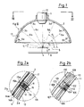
- the point (4) on the optical axis (10) and an area around it are optimally illuminated.
- the area around the center point (4) results from the geometric conditions of the carrier (2) (distance from miniature lamps (3) to the center point (4)) in relation to the directional characteristic of the miniature lamps (3) (radiation cone of the miniature lamps (3)).
- the directional characteristic of the miniature lamps (3) is determined by a focusing lens (16 in FIG. 2) on the miniature lamps (3).
- the object (7) is illuminated differently at different angles ( ⁇ ). If the object (7) is only illuminated with a miniature lamp (e.g. 3a), the object (7) is only irradiated from one side at an angle ( ⁇ 1). However, there is also the possibility of irradiating the object (7) with all miniature lamps (3a and 3f) which are arranged in a concentric circle around the optical axis (10). Depending on the number of miniature lamps (3) on such a circle, irradiation from several different sectors can also be realized by a preselected number of adjacent miniature lamps (3) irradiating the object (7) together.
- a miniature lamp e.g. 3a
- the object (7) is only irradiated from one side at an angle ( ⁇ 1).
- all miniature lamps (3a and 3f) which are arranged in a concentric circle around the optical axis (10).
- irradiation from several different sectors can also be realized by a preselected number of adjacent miniature lamps (3) irradiating the object (7) together.
- the lamp holder (12) is aligned perpendicular to the inside (13) of the inner half-shell (2a). This has several advantages. From a manufacturing point of view, a bore for a lamp holder (12) that is perpendicular to a surface is the easiest to produce. Because all miniature lamps (3) are at the same distance from the center (4), all miniature lamps (3) can have the same focusing lens (16).
- the carrier (109) here also consists of an inner (106) and an outer (108) half-shell, the material of the carrier (109) being very soft.
- the inner half-shell (106) is stiffened by elastic rods (110) which connect the rings (102) to one another for fastening the light guide.
- These rings (102) also support the outer half-shell (108), so that there is a cavity (107) between the half-shells (106, 108).
- the light guides (100) are guided to the rings (102) which have an opening for the light guides (100) so that the light guides (100) can be guided into the interior of the rings (102).
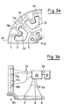
- pushbuttons (32) with light-emitting diodes (31) are arranged in a circle corresponding to the number of miniature lamps (3 in FIG. 1), an extra pushbutton (32a) with light-emitting diode (31a) being provided for incident light.
- the push buttons (32) By pressing the push buttons (32) the miniature lamps (3 in Fig. 1) are selected and simultaneously switched on and off. If a miniature lamp (3) is switched on and selected by pressing its push button (32), the light emitting diode (31) lights up on the push button (32) to indicate the operation of the miniature lamp (3).
- the plus and minus buttons (22) in the second area (26) can be used to change the luminosity of the miniature lamp (3). This change takes place the faster the longer you press the buttons (2).
- the light modulator (43) is constructed as a chip with an area array (for example 256x256 pixels).
- the switching time per pixel is less than 1 »second.
- the light source can thus be switched on and off very quickly without the current through the filament (39) having to be changed.
- a line pattern or a discrete line required for an optical measurement can be imaged very quickly onto the projection plane (41).
- FIG. 5 If two of these light sources (51a and 51b) according to FIG. 5 are built into an illumination device on an optical probe (45) of a measuring machine, then for example a crosshair can be generated on a measuring plane (48). This is shown in Figure 6a.
- the measuring projectors (51a and 51b) are offset by an angle of 90 ° on a plane perpendicular to the optical axis (46) of the optical probe head (45).
- the optical axes (47a and 47b) of the light sources (51a and 51b) intersect the optical axis (46) of the optical probe (45) at a point (44).
- the two lines (52, 54) generated by the measuring projectors then meet exactly in the middle of the captured image section.
- the image according to FIG. 6c is given when the measuring plane (56) is too close. Then the distance between the measuring plane (56) and the optical probe is no longer z, but z- ⁇ z.
- Fig. 6e it is also shown which image of the measuring plane (60) arises when the measuring plane is tilted by the angle ⁇ . Then the one projected line (57) remains in the basic position, while the other projected line (58) takes an oblique course with respect to the first line (57). The same applies correspondingly when the measuring plane is tilted by the angle ⁇ or when the orientations of the measuring plane shown are combined.
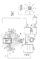
- a lighting device (72) is attached to an optical probe (71) of a measuring machine.
- This probe (71) contains a CCD camera (77) and a lens (73).
- the field of view (86) around the optical axis (78) of the probe head (71) is illuminated by light sources (75, 76, 79, 80) which surround the probe head (71) in two concentric circles.
- the light sources (75, 76, 79, 80) shine on her Light from different angles (83, 84) into the field of view (86), so that there is a different shadow cast in 3-dimensional objects if either only light sources (76, 79) on the inner circle or only light sources (75, 80 ) light up on the outer circle.
- the values determined by the image processing system (97) are made visible to the operator of the measuring machine with the image of the object surface (85) on an image monitor (93) which is connected to the image processing system (97) by a signal line (95).
- the lighting control module (65) is connected to the image processing system (97) via a data bus (92).
- the lighting control module (65) consists of a projection mode memory (87) in which the various parameter settings for each lighting setting are stored. These parameters include the respective luminosity for each light source (75,76,79,80) for each lighting scene.
- the various settings of the individual light modulators (67, 68, 69, 70) for each lighting scene are also saved.
Landscapes
- Physics & Mathematics (AREA)
- General Physics & Mathematics (AREA)
- Spectroscopy & Molecular Physics (AREA)
- Optics & Photonics (AREA)
- Chemical & Material Sciences (AREA)
- Analytical Chemistry (AREA)
- Microscoopes, Condenser (AREA)
- Lenses (AREA)
- Non-Portable Lighting Devices Or Systems Thereof (AREA)
Claims (11)
- Appareil d'observation doté d'un dispositif d'éclairage en lumière réfléchie composé de plusieurs sources de lumière individuelles (3, 9, 75-80, 100) qui forment un groupe régulier multidimensionnel dont le centre coïncide avec l'axe optique (10, 46, 78, 90) de l'optique de reproduction dudit appareil d'observation et qui sont associées à des moyens (25, 35, 65) de réglage individuel de l'intensité de chacune des sources de lumière ou de groupes sélectionnés de sources de lumière, caractérisé en ce que les sources de lumière sont disposées hors du faisceau de reproduction de l'optique de reproduction (1, 73), que les axes de leurs faisceaux d'éclairage présentent des angles d'inclinaison variés par rapport à l'axe optique de l'optique de reproduction et que les moyens de réglage comprennent une mémoire (87) permettant d'enregistrer les réglages d'intensité les plus variés pour les différentes sources de lumière ou les différents groupes de sources de lumière.
- Appareil d'observation selon la revendication 1, caractérisé en ce que plusieurs modulateurs de lumière à effet spatial (43, 51a+b), commandés par voie électronique, sont disposés dans le trajet lumineux des sources de lumière (3,100, 9, 75-80).
- Appareil d'observation selon la revendication 2, caractérisé en ce que plusieurs modulateurs de lumière à effet spatial (43, 51a+b) présentant une distribution symétrique par rapport à l'axe optique (10, 46, 78, 90) du système de reproduction sont disposés à l'intérieur du groupe de sources de lumière et exécutés sous forme de projecteurs de structures lumineuses.
- Appareil d'observation selon la revendication 3, caractérisé en ce que les structures lumineuses reproduites par les projecteurs (43, 51a+b) sur l'objet (7) peuvent être sélectionnées spécifiquement en fonction de l'objet.
- Appareil d'observation selon l'une des revendications 1 - 4, caractérisé en ce que les sources de lumière individuelles (3,100, 9, 75-80) sont des lampes halogènes miniaturisées (3b).
- Appareil d'observation selon les revendications 1 - 5, caractérisé en ce que les sources de lumière individuelles (3,100, 9, 75-80) sont fixées sur la face intérieure d'un support hémisphérique (2,109, 81, 2c-g).
- Appareil d'observation selon la revendication 6, caractérisé en ce que le centre du rayon interne du support (2, 109, 81, 2, 2c-g) coïncide avec ou se trouve à proximité du plan d'objet (5, 48, 85) d'une optique de reproduction associée au dispositif d'éclairage.
- Appareil d'observation selon l'une des revendications 1 - 7, équipé d'un pupitre de commande (37) qui est relié au dispositif d'éclairage et qui comprend des moyens de commande dudit dispositif d'éclairage.
- Appareil d'observation selon l'une des revendications 1 - 8, caractérisé en ce que la commande et le réglage des sources de lumière (3,100, 9, 75-80) et/ou des projecteurs de structures lumineuses (43, 51a+b) sont assurés, en boucle d'asservissement fermée, par un système intelligent de traitement d'images (97) qui permet d'éliminer les caractéristiques des surfaces de l'objet susceptibles de fausser le résultat de la mesure.
- Appareil d'observation selon l'une des revendications 1 - 9, caractérisé en ce que les sources de lumière (3,100, 9, 75-80) et les projecteurs de structures (43, 51a+b) sont disposés dans les plans perpendiculaires à l'axe optique (10, 46, 78, 90), de manière à ce que l'adaptation à différents algorithmes de traitement d'images soit possible.
- Appareil d'observation selon l'une des revendications 1 - 10, caractérisé en ce qu'au moins deux projecteurs de structures lumineuses (43, 51a+b) forment un dispositif autofocus actif qui produit une grandeur de référence z agissant sur un organe de réglage en z.
Applications Claiming Priority (2)
| Application Number | Priority Date | Filing Date | Title |
|---|---|---|---|
| DE3906555 | 1989-03-02 | ||
| DE3906555A DE3906555A1 (de) | 1989-03-02 | 1989-03-02 | Auflicht-objektbeleuchtungseinrichtung |
Publications (3)
| Publication Number | Publication Date |
|---|---|
| EP0385262A2 EP0385262A2 (fr) | 1990-09-05 |
| EP0385262A3 EP0385262A3 (fr) | 1991-12-04 |
| EP0385262B1 true EP0385262B1 (fr) | 1995-08-23 |
Family
ID=6375286
Family Applications (1)
| Application Number | Title | Priority Date | Filing Date |
|---|---|---|---|
| EP90103403A Expired - Lifetime EP0385262B1 (fr) | 1989-03-02 | 1990-02-22 | Appareil d'observation avec système d'illumination réfléchie pour des objets y |
Country Status (4)
| Country | Link |
|---|---|
| US (1) | US5038258A (fr) |
| EP (1) | EP0385262B1 (fr) |
| JP (1) | JP2650215B2 (fr) |
| DE (3) | DE8915535U1 (fr) |
Cited By (1)
| Publication number | Priority date | Publication date | Assignee | Title |
|---|---|---|---|---|
| DE102008055595A1 (de) | 2008-12-30 | 2010-07-01 | Werth Messtechnik Gmbh | Verfahren und Anordnung zum Messen eines Objekts |
Families Citing this family (135)
| Publication number | Priority date | Publication date | Assignee | Title |
|---|---|---|---|---|
| DE4035457A1 (de) * | 1990-11-08 | 1992-05-14 | Messerschmitt Boelkow Blohm | Infrarotscheinwerfer fuer ein ueberwachungssystem |
| US5185638A (en) * | 1991-04-26 | 1993-02-09 | International Business Machines Corporation | Computer controlled, multiple angle illumination system |
| US5309277A (en) * | 1992-06-19 | 1994-05-03 | Zygo Corporation | High intensity illuminator |
| DE4327250C5 (de) * | 1992-09-25 | 2008-11-20 | Carl Zeiss Industrielle Messtechnik Gmbh | Verfahren zur Koordinatenmessung an Werkstücken |
| DE4326473C2 (de) * | 1993-08-06 | 1997-05-15 | European Molecular Biology Lab Embl | Konfokales Mikroskop |
| US5519496A (en) * | 1994-01-07 | 1996-05-21 | Applied Intelligent Systems, Inc. | Illumination system and method for generating an image of an object |
| US5822053A (en) * | 1995-04-25 | 1998-10-13 | Thrailkill; William | Machine vision light source with improved optical efficiency |
| JPH09219768A (ja) * | 1996-02-09 | 1997-08-19 | Canon Inc | イメージセンサ |
| US5690417A (en) * | 1996-05-13 | 1997-11-25 | Optical Gaging Products, Inc. | Surface illuminator with means for adjusting orientation and inclination of incident illumination |
| US6550949B1 (en) | 1996-06-13 | 2003-04-22 | Gentex Corporation | Systems and components for enhancing rear vision from a vehicle |
| JP3749369B2 (ja) | 1997-03-21 | 2006-02-22 | 株式会社竹中工務店 | ハンドポインティング装置 |
| DE19726518B4 (de) * | 1997-06-23 | 2004-02-05 | Suhr, Hajo, Prof. Dr. | In situ Mikroskopsonde für die Partikelmeßtechnik |
| US7038398B1 (en) | 1997-08-26 | 2006-05-02 | Color Kinetics, Incorporated | Kinetic illumination system and methods |
| US20030133292A1 (en) | 1999-11-18 | 2003-07-17 | Mueller George G. | Methods and apparatus for generating and modulating white light illumination conditions |
| JP3047831U (ja) * | 1997-10-08 | 1998-04-28 | 稲畑産業株式会社 | デジタル式光学顕微鏡及び望遠鏡 |
| US6170973B1 (en) | 1997-11-26 | 2001-01-09 | Cognex Corporation | Method and apparatus for wide-angle illumination in line-scanning machine vision devices |
| US5897195A (en) | 1997-12-09 | 1999-04-27 | Optical Gaging, Products, Inc. | Oblique led illuminator device |
| US7598686B2 (en) | 1997-12-17 | 2009-10-06 | Philips Solid-State Lighting Solutions, Inc. | Organic light emitting diode methods and apparatus |
| CA2320153A1 (fr) * | 1997-12-31 | 1999-07-08 | Gentex Corporation | Systeme de vision pour vehicule |
| DE19801978A1 (de) * | 1998-01-20 | 1999-07-29 | Sensor Instr Gmbh | Vorrichtung zum Überprüfen der Beschickung eines Transportarms mit einem Bauteil |
| DE19822255C2 (de) * | 1998-05-18 | 2001-07-05 | Zeiss Carl Jena Gmbh | Auflicht-Beleuchtungsanordnung für ein Stereomikroskop |
| US6179439B1 (en) * | 1998-06-10 | 2001-01-30 | Optical Gaging Products, Inc. | High-incidence programmable surface illuminator for video inspection systems |
| US6240651B1 (en) * | 1998-06-17 | 2001-06-05 | Mycrona Gmbh | Coordinate measuring machine having a non-sensing probe |
| US6161941A (en) * | 1998-08-24 | 2000-12-19 | Intelligent Reasoning Systems, Inc. | Light array system and method for illumination of objects imaged by imaging systems |
| US6598994B1 (en) | 1998-08-24 | 2003-07-29 | Intelligent Reasoning Systems, Inc. | Multi-angle inspection of manufactured products |
| EP1117990A1 (fr) * | 1998-10-01 | 2001-07-25 | Zellweger Luwa Ag | Dispositif de detection de substances etrangeres dans un fil |
| US6441367B1 (en) | 1999-06-02 | 2002-08-27 | Mitutoyo Corporation | Control systems and methods for diffuse illumination |
| US6334699B1 (en) | 1999-04-08 | 2002-01-01 | Mitutoyo Corporation | Systems and methods for diffuse illumination |
| DE19919096A1 (de) * | 1999-04-27 | 2000-11-02 | Zeiss Carl Jena Gmbh | Durchlicht-Beleuchtungseinrichtung für Mikroskope |
| US6633338B1 (en) * | 1999-04-27 | 2003-10-14 | Gsi Lumonics, Inc. | Programmable illuminator for vision system |
| FI114414B (fi) | 1999-05-05 | 2004-10-15 | Outokumpu Oy | Menetelmä ja laitteisto vaahdottuneen aineen pinnan valvomiseksi ja analysoimiseksi |
| AU6238300A (en) | 1999-07-27 | 2001-02-13 | California Cedar Products Company | Automatic circular saw tooth inspection system and method |
| US6454437B1 (en) * | 1999-07-28 | 2002-09-24 | William Kelly | Ring lighting |
| DE19938926C2 (de) * | 1999-08-17 | 2002-08-29 | Schweizer Gmbh Optische Fabrik | Vergrößerndes optisches System, insbesondere vergrößernde optische Sehhilfe |
| US6525303B1 (en) | 1999-09-23 | 2003-02-25 | Mitutoyo Corporation | Control systems and methods for synchronizing diffuse illumination with a camera |
| DE19950899A1 (de) * | 1999-10-22 | 2001-06-07 | Lifatec Gmbh Faseroptik Und Op | Beleuchtbare optische Vergrösserungsvorrichtung |
| DE10066519B3 (de) * | 1999-11-30 | 2019-08-14 | Mitutoyo Corporation | Bilderzeugungssonde |
| DE10017823B4 (de) | 2000-04-10 | 2004-08-26 | Till I.D. Gmbh | Mikroskopische Beleuchtungsvorrichtung |
| EP1150154B1 (fr) * | 2000-04-26 | 2003-03-26 | COBRA electronic GmbH | Procédé et méthode d'illumination annulaire, en particulier système d'illumination incident pour microscopes |
| DE10030772B4 (de) * | 2000-04-26 | 2004-03-18 | Cobra Electronic Gmbh | Auflichtbeleuchtung bei Mikroskopen mit einem um die optische Achse orientierten Ringträger zur Aufnahme von Beleuchtungsmitteln |
| JP2002008410A (ja) * | 2000-06-20 | 2002-01-11 | Ccs Inc | 照明装置 |
| US6618123B2 (en) * | 2000-10-20 | 2003-09-09 | Matsushita Electric Industrial Co., Ltd. | Range-finder, three-dimensional measuring method and light source apparatus |
| DE50213922D1 (de) | 2001-04-03 | 2009-11-26 | Werth Messtechnik Gmbh | Messgerät |
| DE10116588A1 (de) * | 2001-04-03 | 2002-10-10 | Werth Messtechnik Gmbh | Beleuchtungsanordnung sowie Verfahren zum Beleuchten eines Objekts |
| US7152996B2 (en) * | 2001-04-27 | 2006-12-26 | Altman Stage Lighting Co., Inc. | Diode lighting system |
| DE10126887B4 (de) * | 2001-06-01 | 2004-08-12 | Ivoclar Vivadent Ag | Farbfestlegungsvorrichtung |
| EP1262751B1 (fr) * | 2001-06-01 | 2011-04-06 | Ivoclar Vivadent AG | Dispositif et procédé d'analyse de lumière |
| DE10131687A1 (de) * | 2001-06-29 | 2003-01-16 | Eppendorf Ag | Vorrichtung zur Durchführung von Nukleinsäure-Amplifikationsreaktionen bei gleichzeitiger Verfolgung der Bildung von Amplifikationsprodukten |
| DE10135321B4 (de) * | 2001-07-19 | 2005-11-10 | Carl Zeiss Jena Gmbh | Mikroskop und Verfahren zur Untersuchung einer Probe mit einem Mikroskop |
| US20030025906A1 (en) * | 2001-08-06 | 2003-02-06 | Beamworks Ltd. | Optical inspection of solder joints |
| US6749310B2 (en) * | 2001-09-07 | 2004-06-15 | Contrast Lighting Services, Inc. | Wide area lighting effects system |
| US7604361B2 (en) | 2001-09-07 | 2009-10-20 | Litepanels Llc | Versatile lighting apparatus and associated kit |
| US7331681B2 (en) * | 2001-09-07 | 2008-02-19 | Litepanels Llc | Lighting apparatus with adjustable lenses or filters |
| DE10152851A1 (de) * | 2001-10-25 | 2003-05-15 | Daimler Chrysler Ag | Bildverarbeitungssystem |
| JP2005038605A (ja) * | 2002-02-12 | 2005-02-10 | Daisei Denki Kk | 照明器具 |
| JP2003269919A (ja) * | 2002-03-11 | 2003-09-25 | Mitsutoyo Corp | 画像処理型測定機の照明装置 |
| JP3889992B2 (ja) * | 2002-05-17 | 2007-03-07 | 株式会社ミツトヨ | リング照明装置 |
| US7256833B2 (en) * | 2002-05-22 | 2007-08-14 | Avago Technologies Ecbu Ip (Singapore) Pte. Ltd. | Method and apparatus for automatically optimizing optical contrast in automated equipment |
| DE10228985A1 (de) * | 2002-06-28 | 2004-01-15 | Leica Mikrosysteme Gmbh | Beleuchtungseinrichtung für Mikrotome bzw. Ultramikrotome |
| JP3593119B2 (ja) * | 2002-08-01 | 2004-11-24 | 株式会社東芝 | 照明装置 |
| DE10330006B4 (de) * | 2003-07-03 | 2006-07-20 | Leica Microsystems Semiconductor Gmbh | Vorrichtung zur Inspektion eines Wafers |
| JP2005274836A (ja) * | 2004-03-24 | 2005-10-06 | Fujinon Corp | 照明用光源装置 |
| US20050231892A1 (en) * | 2004-04-19 | 2005-10-20 | Harvey Troy A | High energy density electric double-layer capacitor and method for producing the same |
| US7168822B2 (en) * | 2004-11-01 | 2007-01-30 | The Regents Of The Univeristy Of Michigan | Reconfigurable linescan illumination |
| JP4825426B2 (ja) * | 2005-01-31 | 2011-11-30 | 財団法人 東京都医学総合研究所 | 生物顕微鏡に用いる暗視野照明装置 |
| DE102005027312A1 (de) * | 2005-06-13 | 2006-12-14 | Sensovation Ag | Mikroskop |
| DE102005036230B3 (de) * | 2005-08-02 | 2006-11-23 | Leica Microsystems (Schweiz) Ag | Stereomikroskop mit Auflichtbeleuchtungseinrichtung |
| US7488083B2 (en) * | 2005-08-22 | 2009-02-10 | Gentex Corporation | Vehicular rearview components and assemblies |
| DE102006018410A1 (de) * | 2006-04-20 | 2007-10-25 | Carl Zeiss Microimaging Gmbh | Einrichtung zur Kontraststeigerung für Ringlichtbeleuchtungen |
| US7414724B2 (en) * | 2006-11-17 | 2008-08-19 | Eppendorf Ag | Light diffuser used in a testing apparatus |
| DE102007006584B3 (de) * | 2007-02-09 | 2008-06-19 | Leica Microsystems (Schweiz) Ag | Beleuchtungseinrichtung für ein Mikroskop |
| WO2008107951A1 (fr) * | 2007-03-02 | 2008-09-12 | Shimadzu Corporation | Microscope optique confocal |
| WO2008151414A1 (fr) | 2007-06-12 | 2008-12-18 | 1317442 Alberta Ltd. | Loupe et assemblage d'éclairage pour la détection des poussières sur le capteur d'un appareil photo |
| JP4901712B2 (ja) * | 2007-12-25 | 2012-03-21 | 株式会社エルモ社 | 撮像装置 |
| DE102008012478A1 (de) * | 2008-03-04 | 2009-09-10 | Simon Ibv Gmbh | Vorrichtung zur Beleuchtung eines Objekts und räumliches Bildaufnahmesystem |
| DE102008060475A1 (de) * | 2008-12-05 | 2010-06-17 | Bauhaus Universität Weimar | Beleuchtungsvorrichtung für ein optisches Instrument und Verfahren zur Beleuchtung eines mit einem optischen Instrument abzubildenden Objektes |
| EP2188661B1 (fr) * | 2008-04-01 | 2014-07-30 | Bauhaus-Universität Weimar | Procédé et dispositif d'éclairage permettant une amplification du contraste optique |
| DE102008030425A1 (de) * | 2008-06-26 | 2010-01-21 | Siemens Aktiengesellschaft | LED-Beleuchtungssystem für ein elektrisches Prüfsystem |
| US20120025079A1 (en) * | 2010-07-27 | 2012-02-02 | Raulerson David A | Infrared led source for thermal imaging |
| US8657464B2 (en) * | 2011-11-02 | 2014-02-25 | Honeywell International Inc. | Multiple mode light emitting device |
| US12260023B2 (en) | 2012-01-17 | 2025-03-25 | Ultrahaptics IP Two Limited | Systems and methods for machine control |
| US9679215B2 (en) | 2012-01-17 | 2017-06-13 | Leap Motion, Inc. | Systems and methods for machine control |
| US10691219B2 (en) | 2012-01-17 | 2020-06-23 | Ultrahaptics IP Two Limited | Systems and methods for machine control |
| US9070019B2 (en) | 2012-01-17 | 2015-06-30 | Leap Motion, Inc. | Systems and methods for capturing motion in three-dimensional space |
| US8638989B2 (en) | 2012-01-17 | 2014-01-28 | Leap Motion, Inc. | Systems and methods for capturing motion in three-dimensional space |
| US20150253428A1 (en) | 2013-03-15 | 2015-09-10 | Leap Motion, Inc. | Determining positional information for an object in space |
| US11493998B2 (en) | 2012-01-17 | 2022-11-08 | Ultrahaptics IP Two Limited | Systems and methods for machine control |
| US8693731B2 (en) | 2012-01-17 | 2014-04-08 | Leap Motion, Inc. | Enhanced contrast for object detection and characterization by optical imaging |
| US9501152B2 (en) | 2013-01-15 | 2016-11-22 | Leap Motion, Inc. | Free-space user interface and control using virtual constructs |
| US9081175B2 (en) * | 2012-03-23 | 2015-07-14 | Lumos Technology Co., Ltd. | Fluorescence observation device, domed base and fluorescence microscope provided with multiple light sources having different illumination angles |
| WO2013167168A1 (fr) | 2012-05-07 | 2013-11-14 | Carl Zeiss Industrielle Messtechnik Gmbh | Module d'éclairage amélioré pour un appareil de mesure de coordonnées |
| CN104662388B (zh) * | 2012-05-07 | 2018-06-26 | 卡尔蔡司工业测量技术有限公司 | 用于坐标测量机的可替换照明模块 |
| DE102012213819A1 (de) | 2012-08-03 | 2014-05-22 | Leica Microsystems (Schweiz) Ag | Verwendung einer Flächenlichtquelle zur Auflichtbeleuchtung in einem Mikroskop |
| DE102012213826A1 (de) * | 2012-08-03 | 2014-06-12 | Leica Microsystems (Schweiz) Ag | Verwendung einer gerichteten Flächenlichtquelle zur Auflichtbeleuchtung in einem Mikroskop |
| WO2014036120A1 (fr) * | 2012-08-28 | 2014-03-06 | Kla-Tencor Corporation | Éclairage multidirectionnel pour un microscope, et microscope |
| CN103777336B (zh) * | 2012-10-22 | 2017-09-05 | 承奕科技股份有限公司 | 显微光学撷取装置用荧光辅具模组、基架及该装置 |
| CN104238104B (zh) * | 2013-06-20 | 2017-07-21 | 承奕科技股份有限公司 | 具间隔遮罩的荧光观测装置、基架及荧光显微镜 |
| US9459697B2 (en) | 2013-01-15 | 2016-10-04 | Leap Motion, Inc. | Dynamic, free-space user interactions for machine control |
| DE102013006995A1 (de) * | 2013-04-19 | 2014-10-23 | Carl Zeiss Microscopy Gmbh | Ringbeleuchtungsvorrichtung für ein Mikroskopobjektiv und Mikroskopobjektiv |
| US9916009B2 (en) | 2013-04-26 | 2018-03-13 | Leap Motion, Inc. | Non-tactile interface systems and methods |
| US10281987B1 (en) | 2013-08-09 | 2019-05-07 | Leap Motion, Inc. | Systems and methods of free-space gestural interaction |
| US10846942B1 (en) | 2013-08-29 | 2020-11-24 | Ultrahaptics IP Two Limited | Predictive information for free space gesture control and communication |
| US9632572B2 (en) | 2013-10-03 | 2017-04-25 | Leap Motion, Inc. | Enhanced field of view to augment three-dimensional (3D) sensory space for free-space gesture interpretation |
| CN104568859B (zh) * | 2013-10-22 | 2017-10-13 | 承奕科技股份有限公司 | 具多组异角度光源的荧光观测装置、基架及荧光显微镜 |
| US9996638B1 (en) | 2013-10-31 | 2018-06-12 | Leap Motion, Inc. | Predictive information for free space gesture control and communication |
| DE102013112186A1 (de) | 2013-11-06 | 2015-05-07 | Carl Zeiss Industrielle Messtechnik Gmbh | Verbessertes Beleuchtungsmodul für einen Metrologiesensor, insbesondere ein Koordinatenmessgerät |
| US9679197B1 (en) | 2014-03-13 | 2017-06-13 | Leap Motion, Inc. | Biometric aware object detection and tracking |
| US9785247B1 (en) | 2014-05-14 | 2017-10-10 | Leap Motion, Inc. | Systems and methods of tracking moving hands and recognizing gestural interactions |
| US9741169B1 (en) | 2014-05-20 | 2017-08-22 | Leap Motion, Inc. | Wearable augmented reality devices with object detection and tracking |
| DE102014109687B4 (de) | 2014-07-10 | 2020-03-19 | Carl Zeiss Microscopy Gmbh | Positionsbestimmung eines Objekts im Strahlengang einer optischen Vorrichtung |
| CN204480228U (zh) | 2014-08-08 | 2015-07-15 | 厉动公司 | 运动感测和成像设备 |
| JP2016120535A (ja) * | 2014-12-24 | 2016-07-07 | 株式会社ディスコ | 加工装置 |
| US10656720B1 (en) | 2015-01-16 | 2020-05-19 | Ultrahaptics IP Two Limited | Mode switching for integrated gestural interaction and multi-user collaboration in immersive virtual reality environments |
| DE102015100983A1 (de) | 2015-01-23 | 2016-07-28 | Sick Ag | Verfahren zur Lokalisierung von Greifpunkten von Objekten |
| JP6555680B2 (ja) * | 2015-01-26 | 2019-08-07 | オリンパス株式会社 | 顕微鏡用照明装置 |
| JP6251454B2 (ja) * | 2015-03-31 | 2017-12-20 | オリンパス株式会社 | 観察装置および観察方法 |
| DE102015105613B4 (de) | 2015-04-13 | 2023-08-31 | Carl Zeiss Industrielle Messtechnik Gmbh | Auflicht-Beleuchtung für variablen Arbeitsabstand |
| DE102015208772B4 (de) * | 2015-05-12 | 2023-09-28 | Carl Zeiss Industrielle Messtechnik Gmbh | Koordinatenmessgerät mit einer Beleuchtung, über die zumindest eines der Tastelemente eines Tasters beleuchtet werden kann |
| DE102015107517B3 (de) | 2015-05-13 | 2016-06-23 | Carl Zeiss Ag | Vorrichtung und Verfahren zur Bildaufnahme mit erhöhter Schärfentiefe |
| JP6619025B2 (ja) | 2015-12-11 | 2019-12-11 | オリンパス株式会社 | 観察装置 |
| DE112015007195T5 (de) | 2015-12-18 | 2018-08-30 | Olympus Corporation | Beobachtungsvorrichtung |
| DE102015122712B4 (de) | 2015-12-23 | 2023-05-04 | Carl Zeiss Microscopy Gmbh | Vorrichtung und Verfahren zur Bildaufnahme |
| DE102016102971B4 (de) | 2016-02-19 | 2021-02-11 | Carl Zeiss Industrielle Messtechnik Gmbh | Linseneinrichtung für variablen Arbeitsabstand, Beleuchtungsbaugruppe, Koordinatenmessgerät und Verfahren |
| DE102016116311A1 (de) * | 2016-05-02 | 2017-11-02 | Carl Zeiss Microscopy Gmbh | Winkelselektive Beleuchtung |
| WO2018061901A1 (fr) | 2016-09-30 | 2018-04-05 | オリンパス株式会社 | Appareil d'observation |
| EP3521893A1 (fr) | 2016-09-30 | 2019-08-07 | Olympus Corporation | Dispositif d'observation |
| US20180289263A1 (en) * | 2017-03-30 | 2018-10-11 | Nan M. Jokerst | Devices and methods for endoscopic optical assessment of tissue histology |
| JP6308637B1 (ja) * | 2017-05-08 | 2018-04-11 | 国立大学法人福井大学 | 特徴量を用いた3次元計測方法およびその装置 |
| JP6911112B2 (ja) | 2017-05-29 | 2021-07-28 | オリンパス株式会社 | 観察装置 |
| CN109520441A (zh) * | 2019-01-10 | 2019-03-26 | 英特维科技(深圳)有限公司 | 基于线激光的轮廓测量装置及其轮廓测量方法 |
| DE102021202951A1 (de) * | 2021-03-25 | 2022-09-29 | Carl Zeiss Meditec Ag | Medizinisches Gerät zur Ermittlung der räumlichen Lage eines flächig ausgebildeten Markers |
| TWI810639B (zh) * | 2021-08-31 | 2023-08-01 | 達擎股份有限公司 | 口腔成像裝置 |
| US12242047B2 (en) | 2023-06-29 | 2025-03-04 | Mitutoyo Corporation | Metrology system utilizing annular optical configuration |
| US12423779B1 (en) | 2024-04-29 | 2025-09-23 | Mitutoyo Corporation | Metrology system utilizing points-from-focus type processes with glare reduction |
| CN120088625A (zh) * | 2024-10-08 | 2025-06-03 | 深圳市中图仪器股份有限公司 | 确定工件应用图层的方法 |
Family Cites Families (17)
| Publication number | Priority date | Publication date | Assignee | Title |
|---|---|---|---|---|
| DE542371C (de) * | 1930-04-29 | 1932-01-23 | Fernando Perez | Mikroskop |
| DE2852203C3 (de) * | 1978-12-02 | 1982-03-11 | Ibm Deutschland Gmbh, 7000 Stuttgart | Lichtleiteinrichtung für eine mit Auflicht betriebene Abbildungsvorrichtung |
| JPS54135547A (en) * | 1978-04-13 | 1979-10-20 | Hitachi Ltd | Lighting device |
| GB2042164A (en) * | 1979-02-06 | 1980-09-17 | United Glass Ltd | Testing for container defects |
| JPS5651324A (en) * | 1979-10-04 | 1981-05-08 | Sumitomo Electric Ind Ltd | Shrinking method of thermoshrinking tube |
| DE3175773D1 (en) * | 1980-06-10 | 1987-02-05 | Fujitsu Ltd | Pattern position recognition apparatus |
| US4666269A (en) * | 1982-08-09 | 1987-05-19 | Canon Kabushiki Kaisha | Ophthalmologic apparatus |
| US4645348A (en) * | 1983-09-01 | 1987-02-24 | Perceptron, Inc. | Sensor-illumination system for use in three-dimensional measurement of objects and assemblies of objects |
| DE3336125C2 (de) * | 1983-10-05 | 1986-01-23 | Fa. Carl Zeiss, 7920 Heidenheim | Beleuchtungs- oder Laseradapter für Operationsmikroskope |
| US4567551A (en) * | 1984-02-27 | 1986-01-28 | Automation Gages, Inc. | Multi-directional surface illuminator |
| US4614411A (en) * | 1985-05-16 | 1986-09-30 | Carl-Zeiss-Stiftung, Heidenheim/Brenz | Microscope with correlatable fixation target |
| US4706168A (en) * | 1985-11-15 | 1987-11-10 | View Engineering, Inc. | Systems and methods for illuminating objects for vision systems |
| US4821157A (en) * | 1986-02-21 | 1989-04-11 | Hewlett-Packard Co. | System for sensing and forming objects such as leads of electronic components |
| FI78355C (fi) * | 1986-05-27 | 1989-07-10 | Puumalaisen Tutkimuslaitos Oy | Metod foer maetning av glans och apparatur foer tillaempning av metoden. |
| JPH07122694B2 (ja) * | 1986-10-16 | 1995-12-25 | オリンパス光学工業株式会社 | 顕微鏡用照明装置 |
| FI83625C (fi) * | 1987-06-17 | 1991-08-12 | Kone Oy | Foerfarande foer subzoning av en hissgrupp. |
| US4974094A (en) * | 1989-12-04 | 1990-11-27 | Yuhkoh Morito | Direct lighting/illuminating system for miniature CCD camera |
-
1989
- 1989-03-02 DE DE8915535U patent/DE8915535U1/de not_active Expired - Lifetime
- 1989-03-02 DE DE3906555A patent/DE3906555A1/de not_active Withdrawn
-
1990
- 1990-02-22 DE DE59009541T patent/DE59009541D1/de not_active Expired - Fee Related
- 1990-02-22 EP EP90103403A patent/EP0385262B1/fr not_active Expired - Lifetime
- 1990-02-26 US US07/484,890 patent/US5038258A/en not_active Expired - Lifetime
- 1990-03-02 JP JP2049669A patent/JP2650215B2/ja not_active Expired - Lifetime
Cited By (1)
| Publication number | Priority date | Publication date | Assignee | Title |
|---|---|---|---|---|
| DE102008055595A1 (de) | 2008-12-30 | 2010-07-01 | Werth Messtechnik Gmbh | Verfahren und Anordnung zum Messen eines Objekts |
Also Published As
| Publication number | Publication date |
|---|---|
| DE3906555A1 (de) | 1989-07-06 |
| JP2650215B2 (ja) | 1997-09-03 |
| EP0385262A3 (fr) | 1991-12-04 |
| DE8915535U1 (de) | 1990-10-25 |
| US5038258A (en) | 1991-08-06 |
| EP0385262A2 (fr) | 1990-09-05 |
| JPH02272412A (ja) | 1990-11-07 |
| DE59009541D1 (de) | 1995-09-28 |
Similar Documents
| Publication | Publication Date | Title |
|---|---|---|
| EP0385262B1 (fr) | Appareil d'observation avec système d'illumination réfléchie pour des objets y | |
| EP2151622B1 (fr) | Dispositif d'éclairage doté d'un angle de rayonnement variable | |
| EP0485803B1 (fr) | Dispositif de balayage optique avec trajet du faisceau confocal utilisant un réseau de sources de lumière et de détecteurs | |
| DE3527322A1 (de) | Autofokuseinrichtung fuer auflichtmikroskope | |
| AT500056A1 (de) | Optikelement für verkehrszeichen, anzeigetafeln oder dgl. | |
| DE102007027952A1 (de) | Beleuchtungseinrichtung mit zwei nutzbaren Lichtwegen | |
| DE102008017585B4 (de) | Bildsensorsystem | |
| DE102010031678B4 (de) | Schnelle, variable Einfallswinkelbeleuchtung für Maschinensichtinspektionssystem | |
| EP1216650B1 (fr) | Dispositif pour la mesure de la topographie d'une surface | |
| DE69227355T2 (de) | Vorrichtung für vergrösserte beobachtung | |
| DE3242716A1 (de) | Optisches bildformungsgeraet | |
| EP4001748A1 (fr) | Émetteur, ainsi que luminaire doté d'une pluralité de tels émetteurs | |
| DE2744140B2 (de) | Beleuchtungsvorrichtung für ärztliche, insbesondere zahnärztliche Zwecke | |
| DE102023109263B4 (de) | Beleuchtungssystem, spezifische Verwendung eines Beleuchtungssystems, Ausleuchtungsverfahren und Beobachtungssystem | |
| EP4451034A1 (fr) | Lampe médicale | |
| EP0603703A1 (fr) | Appareil de lecture | |
| AT507183B1 (de) | Beleuchtungsvorrichtung mit veränderlichem abstrahlwinkel | |
| DE29922697U1 (de) | Schweinwerfer | |
| DE102024106941A1 (de) | Lichtsteuereinrichtung zum Steuern von Beleuchtungslicht in einem optischen Instrument | |
| WO2024231450A1 (fr) | Dispositif d'éclairage pour éclairer une surface et lentille structurée à double face | |
| DE9202306U1 (de) | Beleuchtungseinrichtung, insbesondere für Bildverarbeitungssysteme | |
| DE102022103885A1 (de) | Intelligentes Aufnahmesystem und Aufnahmeverfahren | |
| DE102022122412A1 (de) | Beleuchtungsvorrichtung und Beleuchtungsverfahren mit Kontrastveränderung | |
| DE10056510A1 (de) | IR-Beleuchtungseinrichtung für eine Vorrichtung zum Erfassen von Eigenschaften einer bewegten Papierbahn | |
| DE102006017912A1 (de) | Beleuchtungssystem zur zeilenförmigen Beleuchtung |
Legal Events
| Date | Code | Title | Description |
|---|---|---|---|
| PUAI | Public reference made under article 153(3) epc to a published international application that has entered the european phase |
Free format text: ORIGINAL CODE: 0009012 |
|
| AK | Designated contracting states |
Kind code of ref document: A2 Designated state(s): CH DE GB IT LI NL SE |
|
| PUAL | Search report despatched |
Free format text: ORIGINAL CODE: 0009013 |
|
| AK | Designated contracting states |
Kind code of ref document: A3 Designated state(s): CH DE GB IT LI NL SE |
|
| 17P | Request for examination filed |
Effective date: 19920401 |
|
| 17Q | First examination report despatched |
Effective date: 19940302 |
|
| ITF | It: translation for a ep patent filed | ||
| GRAA | (expected) grant |
Free format text: ORIGINAL CODE: 0009210 |
|
| AK | Designated contracting states |
Kind code of ref document: B1 Designated state(s): CH DE GB IT LI NL SE |
|
| PG25 | Lapsed in a contracting state [announced via postgrant information from national office to epo] |
Ref country code: NL Free format text: LAPSE BECAUSE OF FAILURE TO SUBMIT A TRANSLATION OF THE DESCRIPTION OR TO PAY THE FEE WITHIN THE PRESCRIBED TIME-LIMIT Effective date: 19950823 |
|
| REF | Corresponds to: |
Ref document number: 59009541 Country of ref document: DE Date of ref document: 19950928 |
|
| PG25 | Lapsed in a contracting state [announced via postgrant information from national office to epo] |
Ref country code: SE Effective date: 19951123 |
|
| GBT | Gb: translation of ep patent filed (gb section 77(6)(a)/1977) |
Effective date: 19951106 |
|
| PGFP | Annual fee paid to national office [announced via postgrant information from national office to epo] |
Ref country code: CH Payment date: 19960126 Year of fee payment: 7 |
|
| NLV1 | Nl: lapsed or annulled due to failure to fulfill the requirements of art. 29p and 29m of the patents act | ||
| PLBE | No opposition filed within time limit |
Free format text: ORIGINAL CODE: 0009261 |
|
| STAA | Information on the status of an ep patent application or granted ep patent |
Free format text: STATUS: NO OPPOSITION FILED WITHIN TIME LIMIT |
|
| 26N | No opposition filed | ||
| PG25 | Lapsed in a contracting state [announced via postgrant information from national office to epo] |
Ref country code: CH Effective date: 19970228 Ref country code: LI Effective date: 19970228 |
|
| REG | Reference to a national code |
Ref country code: CH Ref legal event code: PL |
|
| REG | Reference to a national code |
Ref country code: GB Ref legal event code: IF02 |
|
| RAP2 | Party data changed (patent owner data changed or rights of a patent transferred) |
Owner name: CARL-ZEISS-STIFTUNG TRADING AS CARL ZEISS Owner name: CARL ZEISS |
|
| REG | Reference to a national code |
Ref country code: GB Ref legal event code: 732E |
|
| PG25 | Lapsed in a contracting state [announced via postgrant information from national office to epo] |
Ref country code: IT Free format text: LAPSE BECAUSE OF NON-PAYMENT OF DUE FEES;WARNING: LAPSES OF ITALIAN PATENTS WITH EFFECTIVE DATE BEFORE 2007 MAY HAVE OCCURRED AT ANY TIME BEFORE 2007. THE CORRECT EFFECTIVE DATE MAY BE DIFFERENT FROM THE ONE RECORDED. Effective date: 20050222 |
|
| PGFP | Annual fee paid to national office [announced via postgrant information from national office to epo] |
Ref country code: DE Payment date: 20080219 Year of fee payment: 19 Ref country code: GB Payment date: 20080220 Year of fee payment: 19 |
|
| GBPC | Gb: european patent ceased through non-payment of renewal fee |
Effective date: 20090222 |
|
| PG25 | Lapsed in a contracting state [announced via postgrant information from national office to epo] |
Ref country code: DE Free format text: LAPSE BECAUSE OF NON-PAYMENT OF DUE FEES Effective date: 20090901 |
|
| PG25 | Lapsed in a contracting state [announced via postgrant information from national office to epo] |
Ref country code: GB Free format text: LAPSE BECAUSE OF NON-PAYMENT OF DUE FEES Effective date: 20090222 |