EP2435595B1 - Système de revêtement stratifié présentant une couche de mcralx et une couche riche en chrome, ainsi que procédé pour sa production - Google Patents
Système de revêtement stratifié présentant une couche de mcralx et une couche riche en chrome, ainsi que procédé pour sa production Download PDFInfo
- Publication number
- EP2435595B1 EP2435595B1 EP09788779.8A EP09788779A EP2435595B1 EP 2435595 B1 EP2435595 B1 EP 2435595B1 EP 09788779 A EP09788779 A EP 09788779A EP 2435595 B1 EP2435595 B1 EP 2435595B1
- Authority
- EP
- European Patent Office
- Prior art keywords
- layer
- mcrx
- rich
- chromium
- continuous
- Prior art date
- Legal status (The legal status is an assumption and is not a legal conclusion. Google has not performed a legal analysis and makes no representation as to the accuracy of the status listed.)
- Active
Links
Images



Classifications
-
- C—CHEMISTRY; METALLURGY
- C23—COATING METALLIC MATERIAL; COATING MATERIAL WITH METALLIC MATERIAL; CHEMICAL SURFACE TREATMENT; DIFFUSION TREATMENT OF METALLIC MATERIAL; COATING BY VACUUM EVAPORATION, BY SPUTTERING, BY ION IMPLANTATION OR BY CHEMICAL VAPOUR DEPOSITION, IN GENERAL; INHIBITING CORROSION OF METALLIC MATERIAL OR INCRUSTATION IN GENERAL
- C23C—COATING METALLIC MATERIAL; COATING MATERIAL WITH METALLIC MATERIAL; SURFACE TREATMENT OF METALLIC MATERIAL BY DIFFUSION INTO THE SURFACE, BY CHEMICAL CONVERSION OR SUBSTITUTION; COATING BY VACUUM EVAPORATION, BY SPUTTERING, BY ION IMPLANTATION OR BY CHEMICAL VAPOUR DEPOSITION, IN GENERAL
- C23C4/00—Coating by spraying the coating material in the molten state, e.g. by flame, plasma or electric discharge
- C23C4/18—After-treatment
-
- C—CHEMISTRY; METALLURGY
- C23—COATING METALLIC MATERIAL; COATING MATERIAL WITH METALLIC MATERIAL; CHEMICAL SURFACE TREATMENT; DIFFUSION TREATMENT OF METALLIC MATERIAL; COATING BY VACUUM EVAPORATION, BY SPUTTERING, BY ION IMPLANTATION OR BY CHEMICAL VAPOUR DEPOSITION, IN GENERAL; INHIBITING CORROSION OF METALLIC MATERIAL OR INCRUSTATION IN GENERAL
- C23C—COATING METALLIC MATERIAL; COATING MATERIAL WITH METALLIC MATERIAL; SURFACE TREATMENT OF METALLIC MATERIAL BY DIFFUSION INTO THE SURFACE, BY CHEMICAL CONVERSION OR SUBSTITUTION; COATING BY VACUUM EVAPORATION, BY SPUTTERING, BY ION IMPLANTATION OR BY CHEMICAL VAPOUR DEPOSITION, IN GENERAL
- C23C10/00—Solid state diffusion of only metal elements or silicon into metallic material surfaces
- C23C10/02—Pretreatment of the material to be coated
-
- C—CHEMISTRY; METALLURGY
- C23—COATING METALLIC MATERIAL; COATING MATERIAL WITH METALLIC MATERIAL; CHEMICAL SURFACE TREATMENT; DIFFUSION TREATMENT OF METALLIC MATERIAL; COATING BY VACUUM EVAPORATION, BY SPUTTERING, BY ION IMPLANTATION OR BY CHEMICAL VAPOUR DEPOSITION, IN GENERAL; INHIBITING CORROSION OF METALLIC MATERIAL OR INCRUSTATION IN GENERAL
- C23C—COATING METALLIC MATERIAL; COATING MATERIAL WITH METALLIC MATERIAL; SURFACE TREATMENT OF METALLIC MATERIAL BY DIFFUSION INTO THE SURFACE, BY CHEMICAL CONVERSION OR SUBSTITUTION; COATING BY VACUUM EVAPORATION, BY SPUTTERING, BY ION IMPLANTATION OR BY CHEMICAL VAPOUR DEPOSITION, IN GENERAL
- C23C28/00—Coating for obtaining at least two superposed coatings either by methods not provided for in a single one of groups C23C2/00 - C23C26/00 or by combinations of methods provided for in subclasses C23C and C25C or C25D
- C23C28/02—Coating for obtaining at least two superposed coatings either by methods not provided for in a single one of groups C23C2/00 - C23C26/00 or by combinations of methods provided for in subclasses C23C and C25C or C25D only coatings only including layers of metallic material
- C23C28/021—Coating for obtaining at least two superposed coatings either by methods not provided for in a single one of groups C23C2/00 - C23C26/00 or by combinations of methods provided for in subclasses C23C and C25C or C25D only coatings only including layers of metallic material including at least one metal alloy layer
-
- C—CHEMISTRY; METALLURGY
- C23—COATING METALLIC MATERIAL; COATING MATERIAL WITH METALLIC MATERIAL; CHEMICAL SURFACE TREATMENT; DIFFUSION TREATMENT OF METALLIC MATERIAL; COATING BY VACUUM EVAPORATION, BY SPUTTERING, BY ION IMPLANTATION OR BY CHEMICAL VAPOUR DEPOSITION, IN GENERAL; INHIBITING CORROSION OF METALLIC MATERIAL OR INCRUSTATION IN GENERAL
- C23C—COATING METALLIC MATERIAL; COATING MATERIAL WITH METALLIC MATERIAL; SURFACE TREATMENT OF METALLIC MATERIAL BY DIFFUSION INTO THE SURFACE, BY CHEMICAL CONVERSION OR SUBSTITUTION; COATING BY VACUUM EVAPORATION, BY SPUTTERING, BY ION IMPLANTATION OR BY CHEMICAL VAPOUR DEPOSITION, IN GENERAL
- C23C28/00—Coating for obtaining at least two superposed coatings either by methods not provided for in a single one of groups C23C2/00 - C23C26/00 or by combinations of methods provided for in subclasses C23C and C25C or C25D
- C23C28/02—Coating for obtaining at least two superposed coatings either by methods not provided for in a single one of groups C23C2/00 - C23C26/00 or by combinations of methods provided for in subclasses C23C and C25C or C25D only coatings only including layers of metallic material
- C23C28/021—Coating for obtaining at least two superposed coatings either by methods not provided for in a single one of groups C23C2/00 - C23C26/00 or by combinations of methods provided for in subclasses C23C and C25C or C25D only coatings only including layers of metallic material including at least one metal alloy layer
- C23C28/022—Coating for obtaining at least two superposed coatings either by methods not provided for in a single one of groups C23C2/00 - C23C26/00 or by combinations of methods provided for in subclasses C23C and C25C or C25D only coatings only including layers of metallic material including at least one metal alloy layer with at least one MCrAlX layer
-
- C—CHEMISTRY; METALLURGY
- C23—COATING METALLIC MATERIAL; COATING MATERIAL WITH METALLIC MATERIAL; CHEMICAL SURFACE TREATMENT; DIFFUSION TREATMENT OF METALLIC MATERIAL; COATING BY VACUUM EVAPORATION, BY SPUTTERING, BY ION IMPLANTATION OR BY CHEMICAL VAPOUR DEPOSITION, IN GENERAL; INHIBITING CORROSION OF METALLIC MATERIAL OR INCRUSTATION IN GENERAL
- C23C—COATING METALLIC MATERIAL; COATING MATERIAL WITH METALLIC MATERIAL; SURFACE TREATMENT OF METALLIC MATERIAL BY DIFFUSION INTO THE SURFACE, BY CHEMICAL CONVERSION OR SUBSTITUTION; COATING BY VACUUM EVAPORATION, BY SPUTTERING, BY ION IMPLANTATION OR BY CHEMICAL VAPOUR DEPOSITION, IN GENERAL
- C23C28/00—Coating for obtaining at least two superposed coatings either by methods not provided for in a single one of groups C23C2/00 - C23C26/00 or by combinations of methods provided for in subclasses C23C and C25C or C25D
- C23C28/02—Coating for obtaining at least two superposed coatings either by methods not provided for in a single one of groups C23C2/00 - C23C26/00 or by combinations of methods provided for in subclasses C23C and C25C or C25D only coatings only including layers of metallic material
- C23C28/023—Coating for obtaining at least two superposed coatings either by methods not provided for in a single one of groups C23C2/00 - C23C26/00 or by combinations of methods provided for in subclasses C23C and C25C or C25D only coatings only including layers of metallic material only coatings of metal elements only
-
- C—CHEMISTRY; METALLURGY
- C23—COATING METALLIC MATERIAL; COATING MATERIAL WITH METALLIC MATERIAL; CHEMICAL SURFACE TREATMENT; DIFFUSION TREATMENT OF METALLIC MATERIAL; COATING BY VACUUM EVAPORATION, BY SPUTTERING, BY ION IMPLANTATION OR BY CHEMICAL VAPOUR DEPOSITION, IN GENERAL; INHIBITING CORROSION OF METALLIC MATERIAL OR INCRUSTATION IN GENERAL
- C23C—COATING METALLIC MATERIAL; COATING MATERIAL WITH METALLIC MATERIAL; SURFACE TREATMENT OF METALLIC MATERIAL BY DIFFUSION INTO THE SURFACE, BY CHEMICAL CONVERSION OR SUBSTITUTION; COATING BY VACUUM EVAPORATION, BY SPUTTERING, BY ION IMPLANTATION OR BY CHEMICAL VAPOUR DEPOSITION, IN GENERAL
- C23C28/00—Coating for obtaining at least two superposed coatings either by methods not provided for in a single one of groups C23C2/00 - C23C26/00 or by combinations of methods provided for in subclasses C23C and C25C or C25D
- C23C28/30—Coatings combining at least one metallic layer and at least one inorganic non-metallic layer
- C23C28/32—Coatings combining at least one metallic layer and at least one inorganic non-metallic layer including at least one pure metallic layer
- C23C28/321—Coatings combining at least one metallic layer and at least one inorganic non-metallic layer including at least one pure metallic layer with at least one metal alloy layer
-
- C—CHEMISTRY; METALLURGY
- C23—COATING METALLIC MATERIAL; COATING MATERIAL WITH METALLIC MATERIAL; CHEMICAL SURFACE TREATMENT; DIFFUSION TREATMENT OF METALLIC MATERIAL; COATING BY VACUUM EVAPORATION, BY SPUTTERING, BY ION IMPLANTATION OR BY CHEMICAL VAPOUR DEPOSITION, IN GENERAL; INHIBITING CORROSION OF METALLIC MATERIAL OR INCRUSTATION IN GENERAL
- C23C—COATING METALLIC MATERIAL; COATING MATERIAL WITH METALLIC MATERIAL; SURFACE TREATMENT OF METALLIC MATERIAL BY DIFFUSION INTO THE SURFACE, BY CHEMICAL CONVERSION OR SUBSTITUTION; COATING BY VACUUM EVAPORATION, BY SPUTTERING, BY ION IMPLANTATION OR BY CHEMICAL VAPOUR DEPOSITION, IN GENERAL
- C23C28/00—Coating for obtaining at least two superposed coatings either by methods not provided for in a single one of groups C23C2/00 - C23C26/00 or by combinations of methods provided for in subclasses C23C and C25C or C25D
- C23C28/30—Coatings combining at least one metallic layer and at least one inorganic non-metallic layer
- C23C28/32—Coatings combining at least one metallic layer and at least one inorganic non-metallic layer including at least one pure metallic layer
- C23C28/321—Coatings combining at least one metallic layer and at least one inorganic non-metallic layer including at least one pure metallic layer with at least one metal alloy layer
- C23C28/3215—Coatings combining at least one metallic layer and at least one inorganic non-metallic layer including at least one pure metallic layer with at least one metal alloy layer at least one MCrAlX layer
-
- C—CHEMISTRY; METALLURGY
- C23—COATING METALLIC MATERIAL; COATING MATERIAL WITH METALLIC MATERIAL; CHEMICAL SURFACE TREATMENT; DIFFUSION TREATMENT OF METALLIC MATERIAL; COATING BY VACUUM EVAPORATION, BY SPUTTERING, BY ION IMPLANTATION OR BY CHEMICAL VAPOUR DEPOSITION, IN GENERAL; INHIBITING CORROSION OF METALLIC MATERIAL OR INCRUSTATION IN GENERAL
- C23C—COATING METALLIC MATERIAL; COATING MATERIAL WITH METALLIC MATERIAL; SURFACE TREATMENT OF METALLIC MATERIAL BY DIFFUSION INTO THE SURFACE, BY CHEMICAL CONVERSION OR SUBSTITUTION; COATING BY VACUUM EVAPORATION, BY SPUTTERING, BY ION IMPLANTATION OR BY CHEMICAL VAPOUR DEPOSITION, IN GENERAL
- C23C28/00—Coating for obtaining at least two superposed coatings either by methods not provided for in a single one of groups C23C2/00 - C23C26/00 or by combinations of methods provided for in subclasses C23C and C25C or C25D
- C23C28/30—Coatings combining at least one metallic layer and at least one inorganic non-metallic layer
- C23C28/32—Coatings combining at least one metallic layer and at least one inorganic non-metallic layer including at least one pure metallic layer
- C23C28/322—Coatings combining at least one metallic layer and at least one inorganic non-metallic layer including at least one pure metallic layer only coatings of metal elements only
-
- C—CHEMISTRY; METALLURGY
- C23—COATING METALLIC MATERIAL; COATING MATERIAL WITH METALLIC MATERIAL; CHEMICAL SURFACE TREATMENT; DIFFUSION TREATMENT OF METALLIC MATERIAL; COATING BY VACUUM EVAPORATION, BY SPUTTERING, BY ION IMPLANTATION OR BY CHEMICAL VAPOUR DEPOSITION, IN GENERAL; INHIBITING CORROSION OF METALLIC MATERIAL OR INCRUSTATION IN GENERAL
- C23C—COATING METALLIC MATERIAL; COATING MATERIAL WITH METALLIC MATERIAL; SURFACE TREATMENT OF METALLIC MATERIAL BY DIFFUSION INTO THE SURFACE, BY CHEMICAL CONVERSION OR SUBSTITUTION; COATING BY VACUUM EVAPORATION, BY SPUTTERING, BY ION IMPLANTATION OR BY CHEMICAL VAPOUR DEPOSITION, IN GENERAL
- C23C28/00—Coating for obtaining at least two superposed coatings either by methods not provided for in a single one of groups C23C2/00 - C23C26/00 or by combinations of methods provided for in subclasses C23C and C25C or C25D
- C23C28/30—Coatings combining at least one metallic layer and at least one inorganic non-metallic layer
- C23C28/34—Coatings combining at least one metallic layer and at least one inorganic non-metallic layer including at least one inorganic non-metallic material layer, e.g. metal carbide, nitride, boride, silicide layer and their mixtures, enamels, phosphates and sulphates
- C23C28/345—Coatings combining at least one metallic layer and at least one inorganic non-metallic layer including at least one inorganic non-metallic material layer, e.g. metal carbide, nitride, boride, silicide layer and their mixtures, enamels, phosphates and sulphates with at least one oxide layer
-
- C—CHEMISTRY; METALLURGY
- C23—COATING METALLIC MATERIAL; COATING MATERIAL WITH METALLIC MATERIAL; CHEMICAL SURFACE TREATMENT; DIFFUSION TREATMENT OF METALLIC MATERIAL; COATING BY VACUUM EVAPORATION, BY SPUTTERING, BY ION IMPLANTATION OR BY CHEMICAL VAPOUR DEPOSITION, IN GENERAL; INHIBITING CORROSION OF METALLIC MATERIAL OR INCRUSTATION IN GENERAL
- C23C—COATING METALLIC MATERIAL; COATING MATERIAL WITH METALLIC MATERIAL; SURFACE TREATMENT OF METALLIC MATERIAL BY DIFFUSION INTO THE SURFACE, BY CHEMICAL CONVERSION OR SUBSTITUTION; COATING BY VACUUM EVAPORATION, BY SPUTTERING, BY ION IMPLANTATION OR BY CHEMICAL VAPOUR DEPOSITION, IN GENERAL
- C23C28/00—Coating for obtaining at least two superposed coatings either by methods not provided for in a single one of groups C23C2/00 - C23C26/00 or by combinations of methods provided for in subclasses C23C and C25C or C25D
- C23C28/30—Coatings combining at least one metallic layer and at least one inorganic non-metallic layer
- C23C28/34—Coatings combining at least one metallic layer and at least one inorganic non-metallic layer including at least one inorganic non-metallic material layer, e.g. metal carbide, nitride, boride, silicide layer and their mixtures, enamels, phosphates and sulphates
- C23C28/345—Coatings combining at least one metallic layer and at least one inorganic non-metallic layer including at least one inorganic non-metallic material layer, e.g. metal carbide, nitride, boride, silicide layer and their mixtures, enamels, phosphates and sulphates with at least one oxide layer
- C23C28/3455—Coatings combining at least one metallic layer and at least one inorganic non-metallic layer including at least one inorganic non-metallic material layer, e.g. metal carbide, nitride, boride, silicide layer and their mixtures, enamels, phosphates and sulphates with at least one oxide layer with a refractory ceramic layer, e.g. refractory metal oxide, ZrO2, rare earth oxides or a thermal barrier system comprising at least one refractory oxide layer
-
- Y—GENERAL TAGGING OF NEW TECHNOLOGICAL DEVELOPMENTS; GENERAL TAGGING OF CROSS-SECTIONAL TECHNOLOGIES SPANNING OVER SEVERAL SECTIONS OF THE IPC; TECHNICAL SUBJECTS COVERED BY FORMER USPC CROSS-REFERENCE ART COLLECTIONS [XRACs] AND DIGESTS
- Y02—TECHNOLOGIES OR APPLICATIONS FOR MITIGATION OR ADAPTATION AGAINST CLIMATE CHANGE
- Y02T—CLIMATE CHANGE MITIGATION TECHNOLOGIES RELATED TO TRANSPORTATION
- Y02T50/00—Aeronautics or air transport
- Y02T50/60—Efficient propulsion technologies, e.g. for aircraft
-
- Y—GENERAL TAGGING OF NEW TECHNOLOGICAL DEVELOPMENTS; GENERAL TAGGING OF CROSS-SECTIONAL TECHNOLOGIES SPANNING OVER SEVERAL SECTIONS OF THE IPC; TECHNICAL SUBJECTS COVERED BY FORMER USPC CROSS-REFERENCE ART COLLECTIONS [XRACs] AND DIGESTS
- Y10—TECHNICAL SUBJECTS COVERED BY FORMER USPC
- Y10T—TECHNICAL SUBJECTS COVERED BY FORMER US CLASSIFICATION
- Y10T428/00—Stock material or miscellaneous articles
- Y10T428/12—All metal or with adjacent metals
- Y10T428/12493—Composite; i.e., plural, adjacent, spatially distinct metal components [e.g., layers, joint, etc.]
- Y10T428/12771—Transition metal-base component
- Y10T428/12861—Group VIII or IB metal-base component
- Y10T428/12944—Ni-base component
Definitions
- the invention relates to a layered system with a MCrAlX layer, a Cr-rich layer that is uniquely resistant to both oxidation and hot corrosion and a method to produce such a system.
- a MCrAlX layer Preferably an aluminide layer is applied.
- EP0587341 describes a high temperature corrosion resistant composite coating where the process includes the following steps:
- EP 1327702 describes a MCrAlY coating system comprising an inner layer of beta-NiAl and an outer layer of gamma/beta-MCrAlY and TBC.
- the oxidation resistance can be improved for these layers of coating by adding 0.1-4% Si.
- the coatings are deposited using a gas phase method, CVD, PVD etc..
- US 2005/0003227 describes a similar system as in US 227, but here is also an intermediate layer of a platinum type of metal included. In the document it is stated that the oxidation resistance can be improved for these layers of coating by adding 0.1-4% Si.
- EP 1029100/ US 6416882 describes a MCrAlY type of bond coat comprising up to 2% silicon.
- Aluminide and/or chromium modified coating systems are also described in US 7,229,701 , US 6,183,888 , US 7,060,366 , US 6,287,644 , EP 1 082 216 , US 6,001,492 , US 5,507,623 , EP 1 541 808 and US 6,569,492 .
- EP 0587341 describes a high temperature corrosion resistant composite coating where the process includes the following steps:
- the problem is solved by a layer system according to claim 1 and a method to produce it according to claim 16.
- the concept behind the invention is based on different coating chemistries being suited to protect a substrate within certain temperature and environmental criteria.
- an outer ⁇ -NiAl-layer provides the protection by forming a tenacious thin Alumina oxide in reaction with the high temperature and oxygen in the system, this reaction is typical of the similar ⁇ -NiAl coatings found in industry and well documented in literature.
- temperatures of around 750°C to 800°C up to around 950°C a broad front attack can occur depleting unprotected substrate materials of Cr and Al. Again the use of an Alumina forming ⁇ -NiAl coating will protect against type I corrosion.
- a strain complaint base layer is added in the form of an MCrAlY coating, which provides a degree of strain compliance as well as a final layer of protection should the ⁇ -NiAl and ⁇ -Cr be compromised.
- the layered coating structure essentially allows the environment to "select" the coating composition most suitable to provide protection. The concept can be clearly demonstrated in figure 3 .
- the introduction of Si or other beneficial elements can increase the expected life of the ⁇ -Cr layer.
- Figure 1 shows one exemplary component 1 as a layer system of the invention.
- the component 1 has a metallic substrate 4 which preferably comprises a heat resistant cast or wrought nickel or cobalt alloy, which is preferably Hastelloy X.
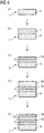
- MCrX layer 7 On the substrate 4 in (a.) in Fig. 4 ) an inner or lowest MCrX layer 7 is applied, especially only one MCrX layer 7 is applied in (b.) in Fig. 4 ) where X is yttrium (Y) and/or silicon (Si) and/or boron (B) and/or aluminum (Al).
- the inner MCrX layer 7 comprises MCrAlX' with X' at least Yttrium (Y) and is preferably only Yttrium (Y).
- This inner MCrAlX' layer 7 comprises especially a NiCrAlY layer and very especially comprises in at% Ni, 22% Cr, 10% Al, 1,0% Y, especially consists of Amdry 962.
- the inner MCrX layer 7 is preferably applied by HVOF.
- the inner MCrX layer 7 is direct on the substrate 4.
- a chromium rich layer 10 is applied on (c.) in Fig. 4 )), that is an ⁇ -Cr-layer.
- the chromizing is preferably performed from 1000°C to 1150°C preferably from 1 to 6 hours, very preferably at 1050°C -1075°C for 2h to 4h.
- the chromizing treatment will lead at least partly to a diffusion layer on the inner layer 7 (Therefore the reference 7 in Fig 4 c) represents the thickness of the inner layer 7 or that a diffusion layer is present and not one composition).
- the chromium rich layer 10 is preferably a diffusion layer.
- This layer system 1 is preferably heat treated, so that the overlay Cr layer is diffused into the inner MCrAlX' layer 7.
- a first outer MCrX'' layer 13 is applied on which is preferably the outer most layer (d.) in Fig. 4 ).
- This MCrX'' layer X'' is preferably yttrium (Y), silicon (Si) and boron (B).
- the first outer MCrX'' layer 13 can be a silicon and/or boron-containing nickel chromium alloy Ni-Cr-Si-B.
- This first outer MCrX'' layer 13 has a different composition than the inner layer 7 and is very especially a NiCrSiB layer (Amdry 103 which consists of in at% 74% Ni, 17% Cr, 9.2% Y, 9%Si, 0.1% B).
- a stabilizing heat treatment is preferably performed. This stabilizing heat treatment is performed at temperatures preferably 1000°C to 1200°C preferably for 1 to 6 hours, preferably at 1000 to 1025°C for 6h.
- a second outer layer 19 is present on or in the first outer layer 13.
- the second outer layer 19 is an aluminum rich layer as shown in figure 3 .
- the outer layer 19 is a diffusion layer.
- the first outer MCrX'' layer 13 can be aluminized to achieve the second outer layer 19 (e.) in Fig. 4 ).
- the aluminizing treatment is performed at temperatures preferably from 1050°C to 1115°C preferably for 1 to 10 hours, preferably at 1070°C to 1095°C for 7h.
- a final anneal treatment preferably at 1000°C to 1150°C for 1 to 6 hours, preferably at 1080°C for 2h, very preferably in vacuum.
- the component 1 has a metallic substrate 4 which preferably comprises a heat resistant cast or wrought nickel or cobalt alloy.
- this substrate is preferably "Hastelloy XTM" a commercially available wrought nickel alloy that nominally contains 47% Ni, 22 Cr, 18.5 Fe, 9 Mo, 1.5 Co, 1 Si, 1 Mn, 0.1 C.
- a first inner MCrAlX' layer 7' is applied, where X' is at least yttrium (Y) and is preferably only Yttrium (Y).
- This first inner MCrAlX' layer 7' comprises especially a NiCrAlY layer and very especially comprises in at% 67% Ni, 22% Cr, 10% Al, 1,0% Y, especially consists of Amdry 962.
- the first inner MCrAlX' layer 7' is preferably applied by HVOF.
- a second inner layer 16 is applied on the first inner MCrAlX' layer 7' (c.) in Fig. 5 ).
- This additional layer 16 has a different composition than the first inner layer 7' and is very especially a NiCrSiB layer (Amdry 103 which consists of in at% 74 Ni, I7 Cr, 9.2 Si, 0.1 B).
- the second inner layer 16 is preferably applied by HVOF.
- a chromium rich layer 10 is applied on, especially an ⁇ -Cr-layer (d.) in Fig. 5 , therefore the reference 16 in Fig 5 d) represents the thickness of the inner layer 16 or that a diffusion layer is present and not one composition).
- the chromizing is preferably performed from 1000°C to 1150°C preferably for 1 to 6 hours, preferably at 1050°C - 1075°C for 2h to 4h.
- the chromizing treatment will preferably lead to diffusion layer on the first inner layer 7'.
- This layer system 1 is preferably heat treated, so that the overlay ⁇ -Cr is diffused into the inner MCrAlX' layer 7' .
- an aluminide layer 22 is applied (e.) in Fig. 5 ). This is preferably achieved by Ni-plating the chromium rich layer 10 and aluminizing this plated Ni-Layer.
- the Ni-plate has preferably has a thickness of 10 ⁇ m to 20 ⁇ m.
- an annealing heat treatment after Ni-plating is performed, preferably at 1121°C for preferably 2h. This annealing treatment is preferably performed in vacuum.
- the following aluminizing is performed preferably at 1080°C for preferably 7h.
- a final annealing heat treatment is performed, preferably at 1080°C for 2h. This annealing treatment is preferably performed in vacuum.
- the chromizing or aluminizing can lead to diffusion layers as shown in Figures 4 , 5 or as overlays as shown in Figures 1, 2 or 3 . But this is not limiting. Both features can be present.
- Base coat MCrAlY sprayed by HVOF or Plasma (could be sprayed by suitable alternative such as VPS or LPPS).
- Cr Rich Layer Applied by CVD or above-the-source Chromizing methods. It was found that a 4 h Chromizing cycle was required to ensure a stable Cr layer during subsequent annealing processes.
- Ni Ni plating 10 ⁇ m to 20 ⁇ m
- Aluminizing Applied by CVD or above the source Aluminizing methods. Final annealing would be required to reintroduce the mechanical properties of the substrate materials.
- Figure 6 shows, by way of example, a gas turbine 100 in the form of a longitudinal part section.
- the gas turbine 100 has a rotor 103, which is mounted such that it can rotate about an axis of rotation 102 and has a shaft 101, also known as the turbine rotor.
- the annular combustion chamber 110 is in communication with a, for example annular, hot-gas duct 111 where, for example, four successive turbine stages 112 form the turbine 108.
- Each turbine stage 112 is formed, for example, from two blade or vane rings. As seen in the direction of flow of a working medium 113, a row 125 formed from rotor blades 120 follows a row 115 of guide vanes in the hot-gas duct 111.
- the guide vanes 130 are secured to an inner housing 138 of a stator 143, whereas the rotor blades 120 of a row 125 are fitted to the rotor 103, for example by means of a turbine disk 133.
- a generator or machine (not shown) is coupled to the rotor 103.
- the compressor 105 When the gas turbine 100 is operating, the compressor 105 sucks in air 135 through the intake housing 104 and compresses it. The compressed air which is provided at the turbine-side end of the compressor 105 is passed to the burners 107, where it is mixed with a fuel. The mixture is then burnt in the combustion chamber 110 to form the working medium 133. From there, the working medium 133 flows along the hot-gas duct 111 past the guide vanes 130 and the rotor blades 120. The working medium 113 expands at the rotor blades 120, transferring its momentum, so that the rotor blades 120 drive the rotor 103 and the rotor drives the machine coupled to it.
- the components which are exposed to the hot working medium 113 are subject to thermal loads.
- the guide vanes 130 and rotor blades 120 of the first turbine stage 112, as seen in the direction of flow of the working medium 113, together with the heat shield elements which line the annular combustion chamber 110, are subject to the highest thermal loads. To withstand the temperatures prevailing there, these components can be cooled by means of a coolant.
- substrates of the components it is likewise possible for substrates of the components to have a directional structure, i.e. they are in single-crystal form (SX structure) or include only longitudinally directed grains (DS structure).
- SX structure single-crystal form
- DS structure longitudinally directed grains
- iron-base, nickel-base or cobalt-base superalloys are used as material for the components, in particular for the turbine blades and vanes 120, 130 and components of the combustion chamber 110.
- Superalloys of this type are known, for example, from EP 1 204 776 B1 , EP 1 306 454 , EP 1 319 729 A1 , WO 99/67435 or WO 00/44949 ; these documents form part of the present disclosure with regard to the chemical composition of the alloys.
- the blades and vanes 120, 130 may likewise have coatings to protect against corrosion (MCrAlX; M is at least one element selected from the group consisting of iron (Fe), cobalt (Co), nickel (Ni), X is an active element and stands for yttrium (Y) and/or silicon and/or at least one of the rare earth elements or hafnium). Alloys of this type are known from EP 0 486 489 B1 , EP 0 786 017 B1 , EP 0 412 397 B1 or EP 1 306 454 A1 , which are intended to form part of the present disclosure with regard to the chemical composition.
- a thermal barrier coating consisting, for example, of ZrO 2 , Y 2 O 4 -ZrO 2 , i.e. it is not, is partially or is completely stabilized by yttrium oxide and/or calcium oxide and/or magnesium oxide, may also be present on the MCrAlX.
- Columnar grains are produced in the thermal barrier coating by suitable coating processes, such as for example electron beam physical vapor deposition (EB-PVD).
- the guide vane 130 has a guide vane root (not shown here) facing the inner housing 138 of the turbine 108 and a guide vane head on the opposite side from the guide vane root.
- the guide vane head faces the rotor 103 and is fixed to a securing ring 140 of the stator 143.
- Figure 7 shows a perspective view of a rotor blade 120 or guide vane 130 of a turbo machine, which extends along a longitudinal axis 121.
- the turbo machine may be a gas turbine of an aircraft or of a power plant for generating electricity, a steam turbine or a compressor.
- the blade or vane 120, 130 has a securing region 400, an adjoining blade or vane platform 403 and a main blade or main part 406 in succession along the longitudinal axis 121.
- the vane 130 may have a further platform (not shown) at its vane tip 415.
- a blade or vane root 183 which is used to secure the rotor blades 120, 130 to a shaft or disk (not shown), is formed in the securing region 400.
- the blade or vane root 183 is designed, for example, in hammerhead form. Other configurations, such as fir-tree or dovetail root, are also possible.
- the blade or vane 120, 130 has a leading edge 409 and a trailing edge 412 for a medium which flows past the main blade or vane part 406.
- blades or vanes 120, 130 by way of example, solid metallic materials, in particular superalloys, are used in all regions 400, 403, 406 of the blade or vane 120, 130.
- superalloys of this type are known, for example, from EP 1 204 776 B1 , EP 1 306 454 , EP 1 319 729 A1 , WO 99/67435 or WO 00/44949 ; these documents form part of the present disclosure with regard to the chemical composition of the alloy.
- the blade or vane 120, 130 may in this case be produced by a casting process, also by means of directional solidification, by a forging process, by a milling process or combinations thereof.
- Single-crystal work pieces of this type are produced, for example, by directional solidification from the melt. This involves casting processes in which the liquid metallic alloy is solidified to form the single-crystal structure, i.e. the single-crystal work piece, i.e. directionally. In the process, dendritic crystals are formed in the direction of the heat flux and form either a columnar-crystalline grain structure (i.e. with grains which run over the entire length of the work piece and are referred to in this context, in accordance with the standard terminology, as directionally solidified) or a single-crystal structure, i.e.
- directionally solidified microstructures are referred to in general, this is to be understood as encompassing both single crystals, which do not have any grain boundaries or at most have small-angle grain boundaries, and columnar crystal structures, which do have grain boundaries running in the longitudinal direction, but do not have any transverse grain boundaries. In the case of these latter crystalline structures, it is also possible to refer to directionally solidified microstructures (directionally solidified structures). Processes of this type are known from US 6,024,792 and EP 0 892 090 A1 ; these documents form part of the present disclosure.
- the blades or vanes 120, 130 may also have coatings protecting against corrosion or oxidation, e.g. (MCrAlX; M is at least one element selected from the group consisting of iron (Fe), cobalt (Co), nickel (Ni), X is an active element and stands for yttrium (Y) and/or silicon and/or at least one rare earth element, or hafnium (Hf)). Alloys of this type are known from EP 0 486 489 B1 , EP 0 786 017 B1 , EP 0 412 397 B1 or EP 1 306 454 A1 , which are intended to form part of the present disclosure with regard to the chemical composition of the alloy.
- MrAlX M is at least one element selected from the group consisting of iron (Fe), cobalt (Co), nickel (Ni)
- X is an active element and stands for yttrium (Y) and/or silicon and/or at least one rare earth element, or hafnium (Hf)
- thermal barrier coating consisting, for example, of ZrO 2 ,Y 2 O 4 -ZrO 2 , i.e. which is not, is partially or is completely stabilized by yttrium oxide and/or calcium oxide and/or magnesium oxide, to be present on the MCrAlX.
- Columnar grains are produced in the thermal barrier coating by suitable coating processes, such as for example electron beam physical vapor deposition (EB-PVD).
- refurbishment means that protective layers may have to be removed from components 120, 130 after they have been used (for example by sandblasting). Then, the corrosion and/or oxidation layers or products are removed. If necessary, cracks in the component 120, 130 are also repaired using the solder according to the invention. This is followed by recoating of the component 120, 130, after which the component 120, 130 can be used again.
- the blade or vane 120, 130 may be of solid or hollow design. If the blade or vane 120, 130 is to be cooled, it is hollow and may also include film cooling holes 418 (indicated by dashed lines).
- Figure 8 shows a combustion chamber 110 of a gas turbine 100 ( Fig. 6 ).
- the combustion chamber 110 is configured, for example, as what is known as an annular combustion chamber, in which a multiplicity of burners 107, which are arranged around an axis of rotation 102 in the circumferential direction, open out into a common combustion chamber space 154, with the burners 107 producing flames 156.
- the combustion chamber 110 overall is of annular configuration, positioned around the axis of rotation 102.
- the combustion chamber 110 is designed for a relatively high temperature of the working medium M of approximately 1000°C to 1600°C.
- the combustion chamber wall 153 is provided with an inner lining formed from heat shield elements 155 on its side facing the working medium M.
- Each heat shield element 155 made from an alloy is equipped on the working medium side with a particularly heat-resistant protective layer (MCrAlX layer and/or ceramic coating) or is made from material that is able to withstand high temperatures
- M is at least one element selected from the group consisting of iron (Fe), cobalt (Co), nickel (Ni), X is an active element and stands for yttrium (Y) and/or silicon and/or at least one rare earth element, or hafnium (Hf). Alloys of this type are known from EP 0 486 489 B1 , EP 0 786 017 B1 , EP 0 412 397 B1 or EP 1 306 454 A1 , which are intended to form part of the present disclosure with regard to the chemical composition of the alloy.
- a, for example, ceramic thermal barrier coating to be present on the MCrAlX, consisting, for example, of ZrO 2 ,Y 2 O 4 -ZrO 2 , i.e. it is not, is partially or is completely stabilized by yttrium oxide and/or calcium oxide and/or magnesium oxide.
- the term refurbishment means that protective layers may have to be removed from heat shield elements 155 after they have been used (for example by sandblasting). Then, the corrosion and/or oxidation layers or products are removed. If necessary, cracks in the heat shield element 155 are also repaired using the solder according to the invention. This is followed by recoating of the heat shield elements 155, after which the heat shield elements 155 can be used again.
- the heat shield elements 155 are in this case, for example, hollow and may also include film cooling holes (not shown) which open out into the combustion chamber space 154.
Landscapes
- Chemical & Material Sciences (AREA)
- Engineering & Computer Science (AREA)
- Metallurgy (AREA)
- Organic Chemistry (AREA)
- Chemical Kinetics & Catalysis (AREA)
- Materials Engineering (AREA)
- Mechanical Engineering (AREA)
- Inorganic Chemistry (AREA)
- Ceramic Engineering (AREA)
- Physics & Mathematics (AREA)
- Plasma & Fusion (AREA)
- Other Surface Treatments For Metallic Materials (AREA)
- Turbine Rotor Nozzle Sealing (AREA)
- Coating By Spraying Or Casting (AREA)
- Laminated Bodies (AREA)
Claims (33)
- Système stratifié (1)
comprenant :un substrat métallique (4) ;une seule couche (7) en MCrX comme couche la plus basse (7) sur le substrat (4),étant entendu que X est au moins de l'yttrium (Y) et/ou du silicium (Si) et/ou de l'aluminium (Al) et/ou du bore (B) ;étant entendu que M est du nickel (Ni) et/ou du cobalt (Co), etune couche continue (10) riche en chrome α sur ou dans l'unique couche (7) en MCrX,étant entendu que la couche (7) inférieure en MCrX est présente sur le substrat (4) etsous la couche continue (10) riche en chrome α ;étant entendu qu'une première couche extérieure (13) en MCrX" est présente sur la couche continue (10) riche en chrome α ;étant entendu que X" est au moins de l'Y, du Si et/ou du B. - Système stratifié selon la revendication 1,
étant entendu que la couche la plus basse (7) en MCrX est une couche en MCrAlX',
étant entendu que X' est au moins de l'yttrium (Y). - Système stratifié selon la revendication 2,
étant entendu que la couche (7) en MCrAlX' consiste en un alliage NiCrAlY. - Système stratifié selon la revendication 3,
étant entendu que la couche (7) en NiCrAlY comprend en % en atomes :
67 % de Ni, 22 % de Cr, 10 % d'Al, 1,0 % d'Y. - Système stratifié selon la revendication 1, 2, 3, 4,
étant entendu que la couche continue (10) riche en chrome α est au-dessus de la couche la plus basse (7) en MCrAlX' et/ou
une couche de diffusion à l'intérieur de la couche (7) en MCrAlX'. - Système stratifié selon l'une quelconque des revendications 1-5,
étant entendu que la première couche extérieure (13) en MCrX" consiste en une couche de NiCrSiB
qui comprend 73,7 % de Ni, 17 % de Cr, 9,2 % de Si, 0,1 % de B (en % en atomes). - Système stratifié selon l'une quelconque des revendications 1-6,
étant entendu qu'une deuxième couche extérieure (19) est présente sur ou dans la première couche extérieure (13) en MCrX" ,
laquelle (19) est la couche le plus à l'extérieur. - Système stratifié selon la revendication 7,
étant entendu que la deuxième couche extérieure (19) est une couche riche en aluminium,
une couche en aluminiure ou
une structure en NiAl β. - Système stratifié selon la revendication 6, 7 ou 8,
étant entendu que la deuxième couche extérieure (19) fait partie d'une première couche extérieure (13) aluminisée en MCrX" . - Système stratifié selon la revendication 2
étant entendu que X' est seulement de l'Y. - Système stratifié selon la revendication 1,
étant entendu que X" est seulement du Si et du B. - Système stratifié selon l'une quelconque des revendications précédentes
qui consiste en
un substrat (4) ;
une couche intérieure (7) en MCrX ;
une couche continue (10) riche en chrome α ;
une première couche extérieure (13) en MCrX", et
une deuxième couche extérieure (19). - Système stratifié selon l'une quelconque des revendications précédentes, qui a été soumis à un traitement thermique avant le premier usage.
- Système stratifié selon la revendication 1, 12 ou 13, étant entendu que le substrat (4) consiste en Hastelloy X.
- Système stratifié selon la revendication 1, 2, 3, 4, 6, 7, 8, 11, 12 ou 13,
étant entendu que M est seulement du Ni. - Système stratifié selon la revendication 1,
étant entendu que X est seulement de l'Y, du Si, de l'Al ou du B. - Procédé de production d'un système stratifié (1)
selon la revendication 1 étant entendu que l'on applique sur un substrat métallique (4) une seule couche (7, 7', 16) en MCrX,
en particulier par projection par flamme supersonique (HVOF),
étant entendu que X est au moins de l'yttrium (Y) et/ou du silicium (Si) et/ou de l'aluminium (Al) et/ou du bore (B), et
étant entendu que M est du nickel (Ni) et/ou du cobalt (Co), et
étant entendu que l'on produit une couche continue (10) riche en chrome α sur ou dans la seule couche (7, 7', 16) en MCrX ;
étant entendu qu'une première couche extérieure (13) est une couche (13) en MCrX" et qu'elle est appliquée sur la couche continue (10) riche en chrome α ;
étant entendu que X" est au moins de l'yttrium (Y), du silicium (Si) et/ou du bore (B). - Procédé selon la revendication 17,
étant entendu que l'on applique la couche continue (10) riche en chrome α au moyen d'un traitement de chromisation. - Procédé selon la revendication 17 ou 18,
étant entendu que l'on applique la couche continue (10) riche en chrome α par dépôt chimique en phase vapeur (CVD). - Procédé selon la revendication 17, 18 ou 19,
étant entendu que l'on répète la chromisation,
en particulier quatre fois. - Procédé selon la revendication 17, 18, 19 ou 20,
étant entendu que la première couche extérieure (13) est une couche en MCrX" et qu'elle est appliquée sur la couche continue (10) riche en chrome α par HVOF. - Procédé selon la revendication 21,
étant entendu que l'on exécute un traitement thermique de stabilisation. - Procédé selon la revendication 21 ou 22,
étant entendu que l'on applique une couche extérieure (19) riche en aluminium. - Procédé selon la revendication 17, 18, 19 ou 20,
étant entendu que l'on applique une couche extérieure (19, 22) riche en aluminium. - Procédé selon la revendication 23 ou 24,
étant entendu que l'on exécute l'aluminisation par dépôt en phase vapeur. - Procédé selon la revendication 22, 23 ou 24,
étant entendu que l'on exécute l'aluminisation à 1080 °C. - Procédé selon la revendication 23 ou 25,
étant entendu que le système stratifié est soumis à un traitement thermique après l'aluminisation. - Procédé selon la revendication 17,
étant entendu que l'on applique la couche (10) riche en chrome au moyen d'un traitement de chromisation à une température comprise entre 1050 °C et 1080 °C, pendant 2 h à 4 h. - Procédé selon la revendication 21,
étant entendu que l'on exécute un traitement thermique de stabilisation à 1010 °C et pendant 6 h. - Procédé selon la revendication 21 ou 22,
étant entendu que l'on applique une couche extérieure (19) riche en aluminium par aluminisation. - Procédé selon la revendication 23, 24 ou 29,
étant entendu que l'on exécute l'aluminisation par CVD. - Procédé selon la revendication 22, 23, 24, 29 ou 30,
étant entendu que l'on exécute l'aluminisation à 1080 °C pendant 7 h. - Procédé selon la revendication 23, 25 ou 27,
étant entendu que le système stratifié est soumis à un traitement thermique après l'aluminisation, sous vide, à 1080 °C pendant 2 h.
Applications Claiming Priority (1)
| Application Number | Priority Date | Filing Date | Title |
|---|---|---|---|
| PCT/US2009/003204 WO2010138096A1 (fr) | 2009-05-26 | 2009-05-26 | Système de revêtement stratifié présentant une couche de mcralx et une couche riche en chrome, ainsi que procédé pour sa production |
Publications (2)
| Publication Number | Publication Date |
|---|---|
| EP2435595A1 EP2435595A1 (fr) | 2012-04-04 |
| EP2435595B1 true EP2435595B1 (fr) | 2020-07-29 |
Family
ID=41061161
Family Applications (1)
| Application Number | Title | Priority Date | Filing Date |
|---|---|---|---|
| EP09788779.8A Active EP2435595B1 (fr) | 2009-05-26 | 2009-05-26 | Système de revêtement stratifié présentant une couche de mcralx et une couche riche en chrome, ainsi que procédé pour sa production |
Country Status (6)
| Country | Link |
|---|---|
| US (1) | US9222163B2 (fr) |
| EP (1) | EP2435595B1 (fr) |
| JP (1) | JP5653421B2 (fr) |
| CN (1) | CN102459685B (fr) |
| RU (1) | RU2542870C2 (fr) |
| WO (1) | WO2010138096A1 (fr) |
Families Citing this family (11)
| Publication number | Priority date | Publication date | Assignee | Title |
|---|---|---|---|---|
| FR2972379B1 (fr) * | 2011-03-07 | 2014-01-17 | Snecma | Procede de rechargement local de piece thermomecanique endommagee et piece ainsi realisee, en particulier piece de turbine |
| EP2537959B1 (fr) | 2011-06-22 | 2013-12-25 | MTU Aero Engines GmbH | Revêtement multicouches anti-usure et procédé de fabrication |
| DE102012015586A1 (de) | 2012-08-08 | 2014-05-15 | MTU Aero Engines AG | Duplex Phasen CrAl-Beschichtung für verbesserten Korrosions-/Oxidations-Schutz |
| EP2743369A1 (fr) * | 2012-12-11 | 2014-06-18 | Siemens Aktiengesellschaft | Système de revêtement, procédé de revêtement d'un substrat et composant de turbine à gaz |
| CN104451655B (zh) * | 2013-09-13 | 2018-02-16 | 中国科学院金属研究所 | 抗高温材料用表面合金涂层复合材料、涂层及其制备方法 |
| US10364490B2 (en) | 2013-12-10 | 2019-07-30 | United Technologies Corporation | Chromizing over cathodic arc coating |
| US9721676B2 (en) * | 2014-05-27 | 2017-08-01 | Westinghouse Electric Company, Llc | Deposition of a protective coating including metal-containing and chromium-containing layers on zirconium alloy for nuclear power applications |
| US10239782B2 (en) | 2015-02-26 | 2019-03-26 | Corning Incorporated | Method for controlling surface features on glass-ceramic articles and articles formed therefrom |
| US9758895B2 (en) | 2015-09-03 | 2017-09-12 | King Fahd University Of Petroleum And Minerals | Alumina-coated co-deposit and an electrodeposition method for the manufacture thereof |
| FR3058164B1 (fr) * | 2016-10-27 | 2020-02-07 | Safran | Piece comprenant un substrat en superalliage monocristallin a base de nickel et son procede de fabrication. |
| CN110295383B (zh) * | 2019-07-19 | 2021-04-13 | 中国科学院金属研究所 | 一种Cr改性铝化物涂层及其制备方法 |
Family Cites Families (38)
| Publication number | Priority date | Publication date | Assignee | Title |
|---|---|---|---|---|
| CA1102184A (fr) * | 1975-05-13 | 1981-06-02 | Alfonso L. Baldi | Traitement du metal par diffusion |
| US5499905A (en) * | 1988-02-05 | 1996-03-19 | Siemens Aktiengesellschaft | Metallic component of a gas turbine installation having protective coatings |
| DE58908611D1 (de) | 1989-08-10 | 1994-12-08 | Siemens Ag | Hochtemperaturfeste korrosionsschutzbeschichtung, insbesondere für gasturbinenbauteile. |
| DE3926479A1 (de) | 1989-08-10 | 1991-02-14 | Siemens Ag | Rheniumhaltige schutzbeschichtung, mit grosser korrosions- und/oder oxidationsbestaendigkeit |
| JP2949605B2 (ja) | 1991-09-20 | 1999-09-20 | 株式会社日立製作所 | 合金被覆ガスタービン翼及びその製造方法 |
| GB9218858D0 (en) | 1992-09-05 | 1992-10-21 | Rolls Royce Plc | High temperature corrosion resistant composite coatings |
| US5500252A (en) | 1992-09-05 | 1996-03-19 | Rolls-Royce Plc | High temperature corrosion resistant composite coatings |
| GB9414859D0 (en) * | 1994-07-22 | 1994-09-14 | Baj Coatings Ltd | Protective coating |
| DE59505454D1 (de) | 1994-10-14 | 1999-04-29 | Siemens Ag | Schutzschicht zum schutz eines bauteils gegen korrosion, oxidation und thermische überbeanspruchung sowie verfahren zu ihrer herstellung |
| IL121313A (en) | 1996-07-23 | 2001-03-19 | Rolls Royce Plc | Method of platinum aluminizing single crystal superalloys |
| FR2757181B1 (fr) | 1996-12-12 | 1999-02-12 | Snecma | Procede de realisation d'un revetement protecteur a haute efficacite contre la corrosion a haute temperature pour superalliages, revetement protecteur obtenu par ce procede et pieces protegees par ce revetement |
| GB2322382A (en) * | 1997-02-22 | 1998-08-26 | Rolls Royce Plc | A coated superalloy article |
| EP0861927A1 (fr) | 1997-02-24 | 1998-09-02 | Sulzer Innotec Ag | Procédé de fabrication de structures monocristallines |
| EP0892090B1 (fr) | 1997-02-24 | 2008-04-23 | Sulzer Innotec Ag | Procédé de fabrication de structure monocristallines |
| DE59801544D1 (de) | 1997-11-03 | 2001-10-25 | Siemens Ag | Erzeugnis mit einem schichtsystem zum schutz gegen ein heisses aggressives gas |
| US6001492A (en) | 1998-03-06 | 1999-12-14 | General Electric Company | Graded bond coat for a thermal barrier coating system |
| EP1306454B1 (fr) | 2001-10-24 | 2004-10-06 | Siemens Aktiengesellschaft | Revêtement protecteur contenant du rhénium pour la protection d'un élément contre l'oxydation et la corrosion aux températures élevées |
| JP2002513081A (ja) | 1998-04-29 | 2002-05-08 | シーメンス アクチエンゲゼルシヤフト | 腐食保護層付き製品と腐食保護層の製造方法 |
| WO1999067435A1 (fr) | 1998-06-23 | 1999-12-29 | Siemens Aktiengesellschaft | Alliage a solidification directionnelle a resistance transversale a la rupture amelioree |
| US6231692B1 (en) | 1999-01-28 | 2001-05-15 | Howmet Research Corporation | Nickel base superalloy with improved machinability and method of making thereof |
| US6287644B1 (en) | 1999-07-02 | 2001-09-11 | General Electric Company | Continuously-graded bond coat and method of manufacture |
| JP2003529677A (ja) | 1999-07-29 | 2003-10-07 | シーメンス アクチエンゲゼルシヤフト | 耐熱性の構造部材及びその製造方法 |
| EP1162284A1 (fr) * | 2000-06-05 | 2001-12-12 | Alstom (Switzerland) Ltd | Procédé de réparation d'un composant revêtu |
| DE50112339D1 (de) | 2001-12-13 | 2007-05-24 | Siemens Ag | Hochtemperaturbeständiges Bauteil aus einkristalliner oder polykristalliner Nickel-Basis-Superlegierung |
| EP1327702A1 (fr) | 2002-01-10 | 2003-07-16 | ALSTOM (Switzerland) Ltd | Revêtement de liaison de type MCrAlY et procédé de depôt de ce revêtement de liason de type MCrAlY |
| US7060366B2 (en) | 2003-02-19 | 2006-06-13 | General Electric Company | Article including a substrate with a metallic coating and a chromium-aluminide protective coating thereon, and its preparation and use in component restoration |
| EP1541810A1 (fr) * | 2003-12-11 | 2005-06-15 | Siemens Aktiengesellschaft | Utilisation de revêtement de barrière thermique pour un élément d'une turbine à vapeur et une turbine à vapeur |
| EP1541808A1 (fr) | 2003-12-11 | 2005-06-15 | Siemens Aktiengesellschaft | Elément de turbine avec une couche résistante à la chaleur et l'érosion |
| RU2004104730A (ru) | 2004-02-19 | 2005-08-20 | Борис Александрович Богачёв (RU) Богачёв Борис Александрович (RU) | Способ упрочнения изделий |
| US7229701B2 (en) | 2004-08-26 | 2007-06-12 | Honeywell International, Inc. | Chromium and active elements modified platinum aluminide coatings |
| EP1676938A1 (fr) * | 2004-12-30 | 2006-07-05 | Siemens Aktiengesellschaft | Methode de fabrication d'un component d'une turbine et le component d'une turbine |
| EP1734145A1 (fr) * | 2005-06-13 | 2006-12-20 | Siemens Aktiengesellschaft | Composant ayant un revêtement avec une barrière thermique et une couche resistante à l'erosion, procéde de manufacture et méthode pour son utilisation |
| EP1772529A1 (fr) * | 2005-10-07 | 2007-04-11 | Siemens Aktiengesellschaft | Composition chimique sèche, utilisation de celle-ci composition pour fabriquer un revêtement multicouche et méthode pour fabriquer ce revêtement |
| DE102005060243A1 (de) * | 2005-12-14 | 2007-06-21 | Man Turbo Ag | Verfahren zum Beschichten einer Schaufel und Schaufel einer Gasturbine |
| CA2585992C (fr) | 2006-06-08 | 2014-06-17 | Sulzer Metco (Us) Inc. | Materiaux possedant une aptitude a l'abrasion, contenant de la zircone stabilisee a l'oxyde de dysprosium (dysprosie) |
| ES2527741T3 (es) * | 2006-06-08 | 2015-01-29 | Siemens Aktiengesellschaft | Componente de turbina recubierto y método de recubrimiento de un componente de turbina |
| EP2188412A1 (fr) * | 2007-09-13 | 2010-05-26 | Siemens Aktiengesellschaft | Produit sidérurgique résistant à la corrosion pour récipients sous pression, procédé pour sa fabrication, et élément de turbine à gaz |
| GB0903199D0 (en) * | 2009-02-25 | 2009-04-08 | Univ Birmingham | Thermal barrier coatings for industrial gas turbines |
-
2009
- 2009-05-26 EP EP09788779.8A patent/EP2435595B1/fr active Active
- 2009-05-26 CN CN200980160683.4A patent/CN102459685B/zh active Active
- 2009-05-26 WO PCT/US2009/003204 patent/WO2010138096A1/fr not_active Ceased
- 2009-05-26 RU RU2011152879/02A patent/RU2542870C2/ru active
- 2009-05-26 JP JP2012513019A patent/JP5653421B2/ja active Active
- 2009-05-26 US US13/322,186 patent/US9222163B2/en active Active
Non-Patent Citations (1)
| Title |
|---|
| None * |
Also Published As
| Publication number | Publication date |
|---|---|
| RU2542870C2 (ru) | 2015-02-27 |
| CN102459685A (zh) | 2012-05-16 |
| US9222163B2 (en) | 2015-12-29 |
| JP2012528249A (ja) | 2012-11-12 |
| WO2010138096A1 (fr) | 2010-12-02 |
| CN102459685B (zh) | 2014-11-19 |
| RU2011152879A (ru) | 2013-07-10 |
| EP2435595A1 (fr) | 2012-04-04 |
| US20130040166A1 (en) | 2013-02-14 |
| JP5653421B2 (ja) | 2015-01-14 |
Similar Documents
| Publication | Publication Date | Title |
|---|---|---|
| EP2435595B1 (fr) | Système de revêtement stratifié présentant une couche de mcralx et une couche riche en chrome, ainsi que procédé pour sa production | |
| EP2002030B1 (fr) | Revetement de barriere thermique en couches a forte porosite et composant | |
| EP2385155B1 (fr) | Système de revêtement de barrière thermique en céramique avec deux couches de céramique | |
| US8057924B2 (en) | Layer system comprising two pyrochlore phases | |
| US9556748B2 (en) | Layer system with double MCrAlX metallic layer | |
| WO2011080158A1 (fr) | Revêtement de céramique nano- et micro-structuré faisant barrière thermique | |
| US20110287269A1 (en) | Alloy, protective layer and component | |
| KR20140094659A (ko) | 합금, 보호층 및 부품 | |
| US20100028128A1 (en) | Component with diagonally extending recesses in the surface and process for operating a turbine | |
| EP1837485B1 (fr) | Une pièce avec un revêtement de protection | |
| GB2431932A (en) | Thermal barrier coating system incorporating a pyrochlore. | |
| EP2247765B1 (fr) | MCrAIY-ALLIAGE, PROCÉDÉS DE PRODUCTION D'UNE COUCHE DE MCrAIY-ALLIAGE ET JOINT EN NIDS D'ABEILLE | |
| CN103748266B (zh) | 合金、保护层和构件 | |
| US20130302638A1 (en) | Alloy, protective layer and component | |
| CN103797141A (zh) | 合金、保护层和构件 | |
| US20090155120A1 (en) | Alloy, Protective Layer for Protecting a Component Against Corrosion and/or Oxidation at High Temperatures, and Component | |
| KR101597924B1 (ko) | 2겹 금속층을 포함하는 층 시스템 | |
| US7998600B2 (en) | Dry composition, its use, layer system and coating process | |
| US20130288072A1 (en) | Alloy, protective layer and component | |
| US20130337286A1 (en) | Alloy, protective coating, and component | |
| US20120288730A1 (en) | Alloy, protective layer, and component | |
| GB2439312A (en) | Protective coating for turbine components |
Legal Events
| Date | Code | Title | Description |
|---|---|---|---|
| PUAI | Public reference made under article 153(3) epc to a published international application that has entered the european phase |
Free format text: ORIGINAL CODE: 0009012 |
|
| 17P | Request for examination filed |
Effective date: 20111111 |
|
| AK | Designated contracting states |
Kind code of ref document: A1 Designated state(s): AT BE BG CH CY CZ DE DK EE ES FI FR GB GR HR HU IE IS IT LI LT LU LV MC MK MT NL NO PL PT RO SE SI SK TR |
|
| RIN1 | Information on inventor provided before grant (corrected) |
Inventor name: PADLEY, PAUL Inventor name: LEWIS, THOMAS Inventor name: WEATHERILL, ADRIAN Inventor name: BOX, PAUL Inventor name: WHITEHURST, MICK Inventor name: KIRCHER, THOMAS Inventor name: VENEZIA, JONATHAN Inventor name: SIMMS, NIGEL Inventor name: NICHOLLS, JOHN Inventor name: EVANS, HUGH Inventor name: MCMORDIE, BRUCE Inventor name: WALKER, PAUL, MATHEW |
|
| RAP1 | Party data changed (applicant data changed or rights of an application transferred) |
Owner name: SIEMENS AG Owner name: PRAXAIR S.T. TECHNOLOGIES, INC. |
|
| DAX | Request for extension of the european patent (deleted) | ||
| RAP1 | Party data changed (applicant data changed or rights of an application transferred) |
Owner name: SIEMENS AKTIENGESELLSCHAFT Owner name: PRAXAIR S.T. TECHNOLOGIES, INC. |
|
| 17Q | First examination report despatched |
Effective date: 20131008 |
|
| STAA | Information on the status of an ep patent application or granted ep patent |
Free format text: STATUS: EXAMINATION IS IN PROGRESS |
|
| RAP1 | Party data changed (applicant data changed or rights of an application transferred) |
Owner name: SIEMENS AKTIENGESELLSCHAFT Owner name: PRAXAIR S.T. TECHNOLOGIES, INC. |
|
| GRAP | Despatch of communication of intention to grant a patent |
Free format text: ORIGINAL CODE: EPIDOSNIGR1 |
|
| STAA | Information on the status of an ep patent application or granted ep patent |
Free format text: STATUS: GRANT OF PATENT IS INTENDED |
|
| INTG | Intention to grant announced |
Effective date: 20200422 |
|
| GRAS | Grant fee paid |
Free format text: ORIGINAL CODE: EPIDOSNIGR3 |
|
| GRAA | (expected) grant |
Free format text: ORIGINAL CODE: 0009210 |
|
| STAA | Information on the status of an ep patent application or granted ep patent |
Free format text: STATUS: THE PATENT HAS BEEN GRANTED |
|
| AK | Designated contracting states |
Kind code of ref document: B1 Designated state(s): AT BE BG CH CY CZ DE DK EE ES FI FR GB GR HR HU IE IS IT LI LT LU LV MC MK MT NL NO PL PT RO SE SI SK TR |
|
| REG | Reference to a national code |
Ref country code: GB Ref legal event code: FG4D |
|
| REG | Reference to a national code |
Ref country code: CH Ref legal event code: EP |
|
| REG | Reference to a national code |
Ref country code: AT Ref legal event code: REF Ref document number: 1295874 Country of ref document: AT Kind code of ref document: T Effective date: 20200815 |
|
| REG | Reference to a national code |
Ref country code: IE Ref legal event code: FG4D |
|
| REG | Reference to a national code |
Ref country code: DE Ref legal event code: R096 Ref document number: 602009062513 Country of ref document: DE |
|
| REG | Reference to a national code |
Ref country code: DE Ref legal event code: R081 Ref document number: 602009062513 Country of ref document: DE Owner name: SIEMENS ENERGY GLOBAL GMBH & CO. KG, DE Free format text: FORMER OWNER: PRAXAIR S.T. TECHNOLOGIES, INC., DANBURY, CT, US Ref country code: DE Ref legal event code: R081 Ref document number: 602009062513 Country of ref document: DE Owner name: PRAXAIR S.T. TECHNOLOGIES, INC., DANBURY, US Free format text: FORMER OWNER: PRAXAIR S.T. TECHNOLOGIES, INC., DANBURY, CT, US |
|
| REG | Reference to a national code |
Ref country code: SE Ref legal event code: TRGR |
|
| REG | Reference to a national code |
Ref country code: LT Ref legal event code: MG4D |
|
| REG | Reference to a national code |
Ref country code: NL Ref legal event code: MP Effective date: 20200729 |
|
| REG | Reference to a national code |
Ref country code: AT Ref legal event code: MK05 Ref document number: 1295874 Country of ref document: AT Kind code of ref document: T Effective date: 20200729 |
|
| PG25 | Lapsed in a contracting state [announced via postgrant information from national office to epo] |
Ref country code: PT Free format text: LAPSE BECAUSE OF FAILURE TO SUBMIT A TRANSLATION OF THE DESCRIPTION OR TO PAY THE FEE WITHIN THE PRESCRIBED TIME-LIMIT Effective date: 20201130 Ref country code: FI Free format text: LAPSE BECAUSE OF FAILURE TO SUBMIT A TRANSLATION OF THE DESCRIPTION OR TO PAY THE FEE WITHIN THE PRESCRIBED TIME-LIMIT Effective date: 20200729 Ref country code: ES Free format text: LAPSE BECAUSE OF FAILURE TO SUBMIT A TRANSLATION OF THE DESCRIPTION OR TO PAY THE FEE WITHIN THE PRESCRIBED TIME-LIMIT Effective date: 20200729 Ref country code: HR Free format text: LAPSE BECAUSE OF FAILURE TO SUBMIT A TRANSLATION OF THE DESCRIPTION OR TO PAY THE FEE WITHIN THE PRESCRIBED TIME-LIMIT Effective date: 20200729 Ref country code: BG Free format text: LAPSE BECAUSE OF FAILURE TO SUBMIT A TRANSLATION OF THE DESCRIPTION OR TO PAY THE FEE WITHIN THE PRESCRIBED TIME-LIMIT Effective date: 20201029 Ref country code: LT Free format text: LAPSE BECAUSE OF FAILURE TO SUBMIT A TRANSLATION OF THE DESCRIPTION OR TO PAY THE FEE WITHIN THE PRESCRIBED TIME-LIMIT Effective date: 20200729 Ref country code: GR Free format text: LAPSE BECAUSE OF FAILURE TO SUBMIT A TRANSLATION OF THE DESCRIPTION OR TO PAY THE FEE WITHIN THE PRESCRIBED TIME-LIMIT Effective date: 20201030 Ref country code: NO Free format text: LAPSE BECAUSE OF FAILURE TO SUBMIT A TRANSLATION OF THE DESCRIPTION OR TO PAY THE FEE WITHIN THE PRESCRIBED TIME-LIMIT Effective date: 20201029 Ref country code: AT Free format text: LAPSE BECAUSE OF FAILURE TO SUBMIT A TRANSLATION OF THE DESCRIPTION OR TO PAY THE FEE WITHIN THE PRESCRIBED TIME-LIMIT Effective date: 20200729 |
|
| PG25 | Lapsed in a contracting state [announced via postgrant information from national office to epo] |
Ref country code: PL Free format text: LAPSE BECAUSE OF FAILURE TO SUBMIT A TRANSLATION OF THE DESCRIPTION OR TO PAY THE FEE WITHIN THE PRESCRIBED TIME-LIMIT Effective date: 20200729 Ref country code: LV Free format text: LAPSE BECAUSE OF FAILURE TO SUBMIT A TRANSLATION OF THE DESCRIPTION OR TO PAY THE FEE WITHIN THE PRESCRIBED TIME-LIMIT Effective date: 20200729 Ref country code: IS Free format text: LAPSE BECAUSE OF FAILURE TO SUBMIT A TRANSLATION OF THE DESCRIPTION OR TO PAY THE FEE WITHIN THE PRESCRIBED TIME-LIMIT Effective date: 20201129 |
|
| PG25 | Lapsed in a contracting state [announced via postgrant information from national office to epo] |
Ref country code: NL Free format text: LAPSE BECAUSE OF FAILURE TO SUBMIT A TRANSLATION OF THE DESCRIPTION OR TO PAY THE FEE WITHIN THE PRESCRIBED TIME-LIMIT Effective date: 20200729 |
|
| PG25 | Lapsed in a contracting state [announced via postgrant information from national office to epo] |
Ref country code: CZ Free format text: LAPSE BECAUSE OF FAILURE TO SUBMIT A TRANSLATION OF THE DESCRIPTION OR TO PAY THE FEE WITHIN THE PRESCRIBED TIME-LIMIT Effective date: 20200729 Ref country code: DK Free format text: LAPSE BECAUSE OF FAILURE TO SUBMIT A TRANSLATION OF THE DESCRIPTION OR TO PAY THE FEE WITHIN THE PRESCRIBED TIME-LIMIT Effective date: 20200729 Ref country code: EE Free format text: LAPSE BECAUSE OF FAILURE TO SUBMIT A TRANSLATION OF THE DESCRIPTION OR TO PAY THE FEE WITHIN THE PRESCRIBED TIME-LIMIT Effective date: 20200729 Ref country code: RO Free format text: LAPSE BECAUSE OF FAILURE TO SUBMIT A TRANSLATION OF THE DESCRIPTION OR TO PAY THE FEE WITHIN THE PRESCRIBED TIME-LIMIT Effective date: 20200729 |
|
| REG | Reference to a national code |
Ref country code: DE Ref legal event code: R097 Ref document number: 602009062513 Country of ref document: DE |
|
| PLBE | No opposition filed within time limit |
Free format text: ORIGINAL CODE: 0009261 |
|
| STAA | Information on the status of an ep patent application or granted ep patent |
Free format text: STATUS: NO OPPOSITION FILED WITHIN TIME LIMIT |
|
| PG25 | Lapsed in a contracting state [announced via postgrant information from national office to epo] |
Ref country code: SK Free format text: LAPSE BECAUSE OF FAILURE TO SUBMIT A TRANSLATION OF THE DESCRIPTION OR TO PAY THE FEE WITHIN THE PRESCRIBED TIME-LIMIT Effective date: 20200729 |
|
| 26N | No opposition filed |
Effective date: 20210430 |
|
| PG25 | Lapsed in a contracting state [announced via postgrant information from national office to epo] |
Ref country code: SI Free format text: LAPSE BECAUSE OF FAILURE TO SUBMIT A TRANSLATION OF THE DESCRIPTION OR TO PAY THE FEE WITHIN THE PRESCRIBED TIME-LIMIT Effective date: 20200729 |
|
| REG | Reference to a national code |
Ref country code: CH Ref legal event code: PL |
|
| PG25 | Lapsed in a contracting state [announced via postgrant information from national office to epo] |
Ref country code: CH Free format text: LAPSE BECAUSE OF NON-PAYMENT OF DUE FEES Effective date: 20210531 Ref country code: MC Free format text: LAPSE BECAUSE OF FAILURE TO SUBMIT A TRANSLATION OF THE DESCRIPTION OR TO PAY THE FEE WITHIN THE PRESCRIBED TIME-LIMIT Effective date: 20200729 Ref country code: LI Free format text: LAPSE BECAUSE OF NON-PAYMENT OF DUE FEES Effective date: 20210531 Ref country code: LU Free format text: LAPSE BECAUSE OF NON-PAYMENT OF DUE FEES Effective date: 20210526 |
|
| REG | Reference to a national code |
Ref country code: BE Ref legal event code: MM Effective date: 20210531 |
|
| PG25 | Lapsed in a contracting state [announced via postgrant information from national office to epo] |
Ref country code: IE Free format text: LAPSE BECAUSE OF NON-PAYMENT OF DUE FEES Effective date: 20210526 |
|
| PG25 | Lapsed in a contracting state [announced via postgrant information from national office to epo] |
Ref country code: BE Free format text: LAPSE BECAUSE OF NON-PAYMENT OF DUE FEES Effective date: 20210531 |
|
| REG | Reference to a national code |
Ref country code: GB Ref legal event code: 732E Free format text: REGISTERED BETWEEN 20220908 AND 20220914 |
|
| REG | Reference to a national code |
Ref country code: DE Ref legal event code: R081 Ref document number: 602009062513 Country of ref document: DE Owner name: SIEMENS ENERGY GLOBAL GMBH & CO. KG, DE Free format text: FORMER OWNERS: PRAXAIR S.T. TECHNOLOGIES, INC., DANBURY, CT, US; SIEMENS AKTIENGESELLSCHAFT, 80333 MUENCHEN, DE Ref country code: DE Ref legal event code: R081 Ref document number: 602009062513 Country of ref document: DE Owner name: PRAXAIR S.T. TECHNOLOGIES, INC., DANBURY, US Free format text: FORMER OWNERS: PRAXAIR S.T. TECHNOLOGIES, INC., DANBURY, CT, US; SIEMENS AKTIENGESELLSCHAFT, 80333 MUENCHEN, DE |
|
| REG | Reference to a national code |
Ref country code: DE Ref legal event code: R082 Ref document number: 602009062513 Country of ref document: DE Representative=s name: ROTH, THOMAS, DIPL.-PHYS. DR., DE |
|
| PG25 | Lapsed in a contracting state [announced via postgrant information from national office to epo] |
Ref country code: HU Free format text: LAPSE BECAUSE OF FAILURE TO SUBMIT A TRANSLATION OF THE DESCRIPTION OR TO PAY THE FEE WITHIN THE PRESCRIBED TIME-LIMIT; INVALID AB INITIO Effective date: 20090526 Ref country code: CY Free format text: LAPSE BECAUSE OF FAILURE TO SUBMIT A TRANSLATION OF THE DESCRIPTION OR TO PAY THE FEE WITHIN THE PRESCRIBED TIME-LIMIT Effective date: 20200729 |
|
| PG25 | Lapsed in a contracting state [announced via postgrant information from national office to epo] |
Ref country code: MK Free format text: LAPSE BECAUSE OF FAILURE TO SUBMIT A TRANSLATION OF THE DESCRIPTION OR TO PAY THE FEE WITHIN THE PRESCRIBED TIME-LIMIT Effective date: 20200729 |
|
| PG25 | Lapsed in a contracting state [announced via postgrant information from national office to epo] |
Ref country code: TR Free format text: LAPSE BECAUSE OF FAILURE TO SUBMIT A TRANSLATION OF THE DESCRIPTION OR TO PAY THE FEE WITHIN THE PRESCRIBED TIME-LIMIT Effective date: 20200729 |
|
| PG25 | Lapsed in a contracting state [announced via postgrant information from national office to epo] |
Ref country code: MT Free format text: LAPSE BECAUSE OF FAILURE TO SUBMIT A TRANSLATION OF THE DESCRIPTION OR TO PAY THE FEE WITHIN THE PRESCRIBED TIME-LIMIT Effective date: 20200729 |
|
| PGFP | Annual fee paid to national office [announced via postgrant information from national office to epo] |
Ref country code: DE Payment date: 20250528 Year of fee payment: 17 |
|
| PGFP | Annual fee paid to national office [announced via postgrant information from national office to epo] |
Ref country code: IT Payment date: 20250522 Year of fee payment: 17 |
|
| PGFP | Annual fee paid to national office [announced via postgrant information from national office to epo] |
Ref country code: FR Payment date: 20250526 Year of fee payment: 17 |
|
| PGFP | Annual fee paid to national office [announced via postgrant information from national office to epo] |
Ref country code: SE Payment date: 20250526 Year of fee payment: 17 |
|
| PGFP | Annual fee paid to national office [announced via postgrant information from national office to epo] |
Ref country code: GB Payment date: 20260323 Year of fee payment: 18 |