EP2435672B1 - Abgasnachbehandlungssystem - Google Patents
Abgasnachbehandlungssystem Download PDFInfo
- Publication number
- EP2435672B1 EP2435672B1 EP10722319.0A EP10722319A EP2435672B1 EP 2435672 B1 EP2435672 B1 EP 2435672B1 EP 10722319 A EP10722319 A EP 10722319A EP 2435672 B1 EP2435672 B1 EP 2435672B1
- Authority
- EP
- European Patent Office
- Prior art keywords
- exhaust gas
- aftertreatment system
- partial region
- burner
- exhaust
- Prior art date
- Legal status (The legal status is an assumption and is not a legal conclusion. Google has not performed a legal analysis and makes no representation as to the accuracy of the status listed.)
- Active
Links
Images

Classifications
-
- F—MECHANICAL ENGINEERING; LIGHTING; HEATING; WEAPONS; BLASTING
- F01—MACHINES OR ENGINES IN GENERAL; ENGINE PLANTS IN GENERAL; STEAM ENGINES
- F01N—GAS-FLOW SILENCERS OR EXHAUST APPARATUS FOR MACHINES OR ENGINES IN GENERAL; GAS-FLOW SILENCERS OR EXHAUST APPARATUS FOR INTERNAL-COMBUSTION ENGINES
- F01N3/00—Exhaust or silencing apparatus having means for purifying, rendering innocuous, or otherwise treating exhaust
- F01N3/08—Exhaust or silencing apparatus having means for purifying, rendering innocuous, or otherwise treating exhaust for rendering innocuous
- F01N3/10—Exhaust or silencing apparatus having means for purifying, rendering innocuous, or otherwise treating exhaust for rendering innocuous by thermal or catalytic conversion of noxious components of exhaust
- F01N3/18—Exhaust or silencing apparatus having means for purifying, rendering innocuous, or otherwise treating exhaust for rendering innocuous by thermal or catalytic conversion of noxious components of exhaust characterised by methods of operation; Control
- F01N3/20—Exhaust or silencing apparatus having means for purifying, rendering innocuous, or otherwise treating exhaust for rendering innocuous by thermal or catalytic conversion of noxious components of exhaust characterised by methods of operation; Control specially adapted for catalytic conversion
- F01N3/2006—Periodically heating or cooling catalytic reactors, e.g. at cold starting or overheating
- F01N3/2033—Periodically heating or cooling catalytic reactors, e.g. at cold starting or overheating using a fuel burner or introducing fuel into exhaust duct
-
- F—MECHANICAL ENGINEERING; LIGHTING; HEATING; WEAPONS; BLASTING
- F01—MACHINES OR ENGINES IN GENERAL; ENGINE PLANTS IN GENERAL; STEAM ENGINES
- F01N—GAS-FLOW SILENCERS OR EXHAUST APPARATUS FOR MACHINES OR ENGINES IN GENERAL; GAS-FLOW SILENCERS OR EXHAUST APPARATUS FOR INTERNAL-COMBUSTION ENGINES
- F01N3/00—Exhaust or silencing apparatus having means for purifying, rendering innocuous, or otherwise treating exhaust
- F01N3/02—Exhaust or silencing apparatus having means for purifying, rendering innocuous, or otherwise treating exhaust for cooling, or for removing solid constituents of, exhaust
- F01N3/021—Exhaust or silencing apparatus having means for purifying, rendering innocuous, or otherwise treating exhaust for cooling, or for removing solid constituents of, exhaust by means of filters
- F01N3/023—Exhaust or silencing apparatus having means for purifying, rendering innocuous, or otherwise treating exhaust for cooling, or for removing solid constituents of, exhaust by means of filters using means for regenerating the filters, e.g. by burning trapped particles
- F01N3/0231—Exhaust or silencing apparatus having means for purifying, rendering innocuous, or otherwise treating exhaust for cooling, or for removing solid constituents of, exhaust by means of filters using means for regenerating the filters, e.g. by burning trapped particles using special exhaust apparatus upstream of the filter for producing nitrogen dioxide, e.g. for continuous filter regeneration systems [CRT]
-
- F—MECHANICAL ENGINEERING; LIGHTING; HEATING; WEAPONS; BLASTING
- F01—MACHINES OR ENGINES IN GENERAL; ENGINE PLANTS IN GENERAL; STEAM ENGINES
- F01N—GAS-FLOW SILENCERS OR EXHAUST APPARATUS FOR MACHINES OR ENGINES IN GENERAL; GAS-FLOW SILENCERS OR EXHAUST APPARATUS FOR INTERNAL-COMBUSTION ENGINES
- F01N3/00—Exhaust or silencing apparatus having means for purifying, rendering innocuous, or otherwise treating exhaust
- F01N3/08—Exhaust or silencing apparatus having means for purifying, rendering innocuous, or otherwise treating exhaust for rendering innocuous
- F01N3/10—Exhaust or silencing apparatus having means for purifying, rendering innocuous, or otherwise treating exhaust for rendering innocuous by thermal or catalytic conversion of noxious components of exhaust
- F01N3/105—General auxiliary catalysts, e.g. upstream or downstream of the main catalyst
- F01N3/106—Auxiliary oxidation catalysts
-
- F—MECHANICAL ENGINEERING; LIGHTING; HEATING; WEAPONS; BLASTING
- F01—MACHINES OR ENGINES IN GENERAL; ENGINE PLANTS IN GENERAL; STEAM ENGINES
- F01N—GAS-FLOW SILENCERS OR EXHAUST APPARATUS FOR MACHINES OR ENGINES IN GENERAL; GAS-FLOW SILENCERS OR EXHAUST APPARATUS FOR INTERNAL-COMBUSTION ENGINES
- F01N2240/00—Combination or association of two or more different exhaust treating devices, or of at least one such device with an auxiliary device, not covered by indexing codes F01N2230/00 or F01N2250/00, one of the devices being
- F01N2240/14—Combination or association of two or more different exhaust treating devices, or of at least one such device with an auxiliary device, not covered by indexing codes F01N2230/00 or F01N2250/00, one of the devices being a fuel burner
-
- F—MECHANICAL ENGINEERING; LIGHTING; HEATING; WEAPONS; BLASTING
- F01—MACHINES OR ENGINES IN GENERAL; ENGINE PLANTS IN GENERAL; STEAM ENGINES
- F01N—GAS-FLOW SILENCERS OR EXHAUST APPARATUS FOR MACHINES OR ENGINES IN GENERAL; GAS-FLOW SILENCERS OR EXHAUST APPARATUS FOR INTERNAL-COMBUSTION ENGINES
- F01N2510/00—Surface coverings
- F01N2510/06—Surface coverings for exhaust purification, e.g. catalytic reaction
-
- F—MECHANICAL ENGINEERING; LIGHTING; HEATING; WEAPONS; BLASTING
- F01—MACHINES OR ENGINES IN GENERAL; ENGINE PLANTS IN GENERAL; STEAM ENGINES
- F01N—GAS-FLOW SILENCERS OR EXHAUST APPARATUS FOR MACHINES OR ENGINES IN GENERAL; GAS-FLOW SILENCERS OR EXHAUST APPARATUS FOR INTERNAL-COMBUSTION ENGINES
- F01N2510/00—Surface coverings
- F01N2510/06—Surface coverings for exhaust purification, e.g. catalytic reaction
- F01N2510/068—Surface coverings for exhaust purification, e.g. catalytic reaction characterised by the distribution of the catalytic coatings
- F01N2510/0682—Surface coverings for exhaust purification, e.g. catalytic reaction characterised by the distribution of the catalytic coatings having a discontinuous, uneven or partially overlapping coating of catalytic material, e.g. higher amount of material upstream than downstream or vice versa
-
- F—MECHANICAL ENGINEERING; LIGHTING; HEATING; WEAPONS; BLASTING
- F01—MACHINES OR ENGINES IN GENERAL; ENGINE PLANTS IN GENERAL; STEAM ENGINES
- F01N—GAS-FLOW SILENCERS OR EXHAUST APPARATUS FOR MACHINES OR ENGINES IN GENERAL; GAS-FLOW SILENCERS OR EXHAUST APPARATUS FOR INTERNAL-COMBUSTION ENGINES
- F01N2610/00—Adding substances to exhaust gases
- F01N2610/03—Adding substances to exhaust gases the substance being hydrocarbons, e.g. engine fuel
-
- Y—GENERAL TAGGING OF NEW TECHNOLOGICAL DEVELOPMENTS; GENERAL TAGGING OF CROSS-SECTIONAL TECHNOLOGIES SPANNING OVER SEVERAL SECTIONS OF THE IPC; TECHNICAL SUBJECTS COVERED BY FORMER USPC CROSS-REFERENCE ART COLLECTIONS [XRACs] AND DIGESTS
- Y02—TECHNOLOGIES OR APPLICATIONS FOR MITIGATION OR ADAPTATION AGAINST CLIMATE CHANGE
- Y02T—CLIMATE CHANGE MITIGATION TECHNOLOGIES RELATED TO TRANSPORTATION
- Y02T10/00—Road transport of goods or passengers
- Y02T10/10—Internal combustion engine [ICE] based vehicles
- Y02T10/12—Improving ICE efficiencies
Definitions
- the invention relates to an exhaust gas aftertreatment system for an internal combustion engine.
- it includes an introduction device for introducing hydrocarbons (HCs) into an exhaust pipe carrying the process exhaust gas of the internal combustion engine and a treatment device through which process exhaust gas flows downstream of the introduction site and which increases the process exhaust gas temperature by oxidation of the introduced hydrocarbons.
- HCs hydrocarbons
- Such an exhaust gas aftertreatment system is known from the EP1537304 known.
- This exhaust gas aftertreatment system is designed for connection to compression ignition engines, such as diesel engines.
- the subject of this document is concerned with reducing the total emissions of such a compression ignition engine.
- it is proposed to operate the compression ignition engine in different operating modes and to provide a catalytic component from a predetermined selection in the exhaust system, which has at least one platinum catalyst. It is generally known that platinum catalysts can be used to generate certain predetermined catalytic reactions.
- a liquid HC dosage is usually used in the exhaust gas together with a diesel oxidation catalytic converter, which converts these hydrocarbons and delivers thermal energy to raise the exhaust gas temperature to approximately 600 °.
- the fuel is preferably injected into the exhaust line between the internal combustion engine and the catalytic converter.
- the hydrocarbons are usually provided in the combustion chamber of the internal combustion engine via a late, no longer thermally converted post-injection. All of these systems use catalytic converters that work in significant Dimensions include platinum.
- the much cheaper palladium is also used - primarily for thermal stabilization of the catalyst - but with a maximum mass fraction of around 50% of the total precious metal.
- a so-called "fuel processor” can be used to generate heat in the exhaust line of a diesel engine.
- This treatment device can consist of an oxidation catalytic converter and a reforming catalytic converter, which can possibly use fuel introduced into the exhaust gas to heat a downstream particle trap.
- the US7032376 describes an exhaust gas purification system consisting of certain catalytic units and an upstream burner that generates the heat necessary for the catalytic units.
- catalytic units for the oxidation of hydrocarbons preferably consist of Pt-only catalysts and can contain palladium only in exceptional cases.
- the present invention is based on the object of specifying an exhaust gas aftertreatment system and a method for operating such an exhaust gas aftertreatment system which is capable of heating the exhaust gas of an internal combustion engine and, moreover, can be implemented inexpensively.
- the hydrocarbons in the device are at least partially evaporated and chemically changed by cracking reactions and / or by partial oxidation and the device for at least partial evaporation and by cracking reactions and / or by Partial oxidation caused chemical change of the hydrocarbons is an arrangement which has a burner (2) with a supply device (8a, 8b) for fuel and air, as well as a combustion chamber (3) and an exhaust pipe (4) provided with a spraying device (5) for hydrocarbons ), which opens into the exhaust pipe (6) at the point of introduction, and one downstream of the outlet (7), through which the process exhaust gas flows and which increases the process exhaust gas temperature by oxidation of the introduced, partially evaporated and by cracking reactions and / or by partial oxidation of chemically modified hydrocarbons Contains treatment device having catalytically coated components, the platinum content at least in a partial area of the catalytic coating of the components being less than 50% of the total mass of all catalytically active substances in this partial area of the coating, the palladium content of the cat
- This embodiment is based on the surprising finding that an exhaust gas aftertreatment system which, using a suitable introduction device, already provides the hydrocarbons in a form which has been vaporized in a special way and chemically changed by cracking reactions and / or by partial oxidation, has a considerably lower platinum content in the catalytic components of the subsequent treatment device can work than is the case with conventional hydrocarbon mixtures.
- a goal of introducing the hydrocarbons and conversion in the treatment device is to burn the soot particles filtered out of the process exhaust gas of the internal combustion engine in a particle filter continuously or discontinuously. It was therefore not foreseeable that this could be implemented with great success with the device according to the invention, but nevertheless inexpensively.
- the partial area of the catalytic coating of the components of the treatment device comprises at least 20%, preferably 30%, further preferably 50% and particularly preferably 100% of the total mass of the catalytic coating on the components of the treatment device which increases the process exhaust gas temperature.
- the catalytic coating of the components is understood to mean coatings which have a gradient of greater than +1 K / cm, preferably greater than +2.5 K / cm and particularly preferably greater than +10 K / cm along the direction of flow during the phase of heating the exhaust gas. This ensures that the system functions reliably.
- the catalytic coating of the sub-area preferably contains precious metals with a total noble metal mass based on the component or substrate volume in the range of 0.1-10 g / L, preferably 0.5-5 g / L and particularly preferably in the range of 0.7 3.5 g / L.
- the precious metal portion of the catalytic coating of the partial area of the treatment device is less than 10%, preferably less than 5% and particularly preferably less than 3% of the total mass of the catalytic coating of the partial area under consideration.
- the partial area of the catalytic coating of the treatment device thus contains further catalytically active substances.
- the proportion of noble metals in the total mass of the catalytically active substances is more than 10%, particularly preferably more than 30% and very particularly preferably 100%.
- Palladium is one of the precious metals existing in the partial area, and the proportion of palladium in the catalytic coating of the partial area of the treatment device is at least 50%, preferably at least 75% and particularly preferably 100% of the total mass of all precious metals in the partial area of the treatment device.
- the proportion of platinum in the partial area of the catalytic coating of the components is less than 50%, more preferably less than 30% and very particularly preferably less than 20% or extremely preferably less than 10% of the total mass of all catalytically active substances in this partial area of the coating.
- the platinum content is less than 5%, preferably less than 3% and particularly preferably less than 1% of the total mass of all catalytically active substances in the partial area, that is to say 0% in the limit case.
- catalytically active substances are understood to mean active metals, i.e. Transition metals of groups VB, VIB, VIIB, VIII, IB and IIB and in particular also noble metals, which are able to be selected as part of a catalytic coating with an active metal concentration in the range of 0.1-500 g / L catalyst space, preferably 0.2- 200 g / L and particularly preferably 0.5 - 100 g / L at a temperature of 350 ° C to oxidize a hydrocarbon mixture resulting from the evaporation of diesel fuel in engine exhaust gas with a volume concentration of 1000 ppm C1 at least predominantly to carbon dioxide and water.
- the catalytically active substances or the active metals can be in elemental form and / or in the form of compounds, in particular oxides.
- the catalytic coating of the treatment device can contain further components which, for example, promote the fine distribution of the catalytically active substances or active metals and generally support or even enable their active mechanism.
- these components include, in particular, pure or mixed oxides of aluminum, silicon, titanium, zircon or rare earths, with additions of in particular alkali or alkaline earth elements, halides and / or sulfur or phosphorus compounds and their properties such as acidity can further modify. In principle, further admixtures are possible. Storage components such as zeolites and / or cerium / zirconium mixed oxides are also frequently used.
- the catalytically active substances are usually arranged on these further components or selective parts thereof.
- Precious metals such as Platinum or palladium are predominantly in the form of small particles in the range from 0.1 to 100 nm, preferably 0.2-50 nm and more preferably 0.5-25 nm in diameter.
- the catalytic coating as a whole forms a highly surface and highly porous structure.
- Typical BET surfaces are in the range of 1-300 m 2 / g, preferably 50-200 m 2 / g and particularly preferably in the range of 80-160 m 2 / g; Pore volumes are in the range of 0.1-2 g / L, preferably 0.2-1.5 g / L and particularly preferably in the range of 0.25-1 g / L.
- the catalytic coating is generally in the form of a slip [" Auto exhaust gas catalysts ", Hagelüken et. Al., Expert Verlag, 2nd edition, 2005 ] applied to the component to be coated in one or more steps. In individual cases, solutions or gas phase processes can also be used. Ceramic or metallic substrates are often coated in the form of honeycomb bodies or other structures such as foams, corrugated mats or nonwovens, but in principle smooth components such as the inner walls of pipes can also be coated.
- the substrates can be simple flow-through substrates or substrates with a filter function, in which the medium to be filtered is passed, for example, through a porous ceramic wall or a metal fleece.
- the function of the catalytic coating is to convert the metered oxidizable components, in particular hydrocarbons (HCs), as far as possible into carbon dioxide and water in the inflow gas and to generate heat in the process.
- HCs hydrocarbons
- Parts of these components from the inflow gas can be temporarily stored in the coating in adsorbed or liquid form, particularly functional coatings being characterized in that the functionality is impaired as little as possible by such storage effects.
- Particularly functional catalytic coatings are used due to low hydrocarbon concentrations at the outlet and small radial temperature deviations characterized in particular in the entry region of the temperature-increasing partial region of the treatment device, these properties being maintained as constant as possible over the entire regeneration interval of typically approximately 10 to 20 minutes.
- the catalytic coating is preferably applied in an amount of 5-300 g / L, preferably 10-150 g / L and particularly preferably in the range of 20-130 g / L component or substrate volume.
- the coating preferably has a layer thickness in the range from 5 to 200 ⁇ m, preferably 10-100 ⁇ m and particularly preferably in the range from 20-60 ⁇ m. If noble metal is used as the active component, the total noble metal mass, based on the component or substrate volume, is preferably in the range of 0.1-10 g / L, base noble metals or catalytically active substances can have significantly higher loads and, in extreme cases, make up the complete coating.
- the platinum mass fraction of the catalytically active substances can be 0% in the limit case. At the time of the invention, this was by no means suspected. Frequently, large amounts of expensive platinum are present in these hydrocarbon-oxidizing catalysts.
- the increase in the exhaust gas temperature is preferably brought about via a so-called diesel oxidation catalyst.
- a diesel oxidation catalyst This means that the partial area of the catalytic coating of the components of the treatment device which increases the process exhaust gas temperature represents part or all of such a diesel oxidation catalytic converter.
- the exhaust gas temperature can also be increased or exclusively via a filter to be regenerated.
- no diesel oxidation catalyst is required at all and the hydrocarbon mixture is passed directly onto the catalytically coated particle filter, which in this case is the sole catalytically coated component of the treatment device which increases the process exhaust gas temperature. In this case, it is naturally desirable that sufficient temperatures for regeneration are reached as soon as possible after entering the filter.
- the catalytically coated components which increase the process exhaust gas temperature are catalyst substrates or particle filters, each of which can be coated in a uniform or zonal manner. Coating solutions with one or more superposed, catalytically active layers are also conceivable. Within the scope of the invention it is possible, for example, to design and install a diesel oxidation catalytic converter or another catalytic converter, which can also take on other tasks, with the catalytic coating as an independent component, or ultimately to integrate the diesel oxidation catalytic converter with the catalytic coating into the particle filter. Of course, combination solutions of the two described embodiments are also possible and provided within the scope of the invention.
- the partial area of the treatment device preferably comprises an entire catalytically coated component that increases the process exhaust gas temperature or a part of such a component or parts of several such components.
- Each component can therefore have several sub-areas, which have different properties, of which a sub-area has the properties specified above.
- This partial area does not necessarily have to be the first part of the respective component, but should be arranged at least in the flow direction in the front part of a zonal coating of such a component, in particular a particle filter.
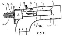
- the introduction device for at least partial evaporation and for chemical changes in the hydrocarbons caused by cracking reactions and / or by partial oxidation is, in a further embodiment, an arrangement which comprises a burner with a supply device for fuel and air and a combustion chamber and one with an injection device for hydrocarbons Exhaust pipe which opens into the exhaust pipe at the point of introduction ( Fig. 2 ).
- the injected hydrocarbons are in the form of liquid fuel, which is preferably the same fuel, for example diesel fuel, which is also injected with the burner supply device.
- a gaseous fuel for example natural gas
- the separate introduction of the additional fuel via the injection device offers the advantage that, in contrast to the prior art, a quantity of fuel that is required for a process, for example, no longer has to be supplied by the burner supply device, but rather a subset of the total fuel required downstream of the burner "Secondary fuel amount" is supplied. This amount of secondary fuel is then processed and / or burned in a completely controlled manner.
- the corresponding operating procedure is characterized in principle by the fact that the burner provides a basic thermal output, the lower limit of which is provided by the provision of a sufficient amount of energy for the vaporization of the exhaust gas line injected amount of fuel is specified.
- a mouth (11) of the injection device (5) in the exhaust line (4) has an atomizing nozzle, in particular a pressure atomizing nozzle or an airflow atomizing nozzle.
- the pressure atomizing nozzle the liquid fuel is atomized solely by the pressure of the fuel.
- the injection device can also be designed as an airflow atomizing nozzle.
- the airflow atomizer nozzle is operated in such a way that the fuel is introduced into the exhaust pipe with a small amount of air.
- an airflow atomizer nozzle for example, 20 L / min air and 2 cm 3 / min fuel would be conveyed to provide an ignitable fuel-air mixture, while with the airflow atomizer nozzle operated according to the invention with 20 L / min air up to 100 cm 3 / min. Fuel to be atomized. Such a rich fuel-air mixture is primarily not ignitable.
- a venturi device is arranged in the exhaust pipe in the region of an opening of the injection device. This causes the partial flows of exhaust gas and evaporated fuel to mix quickly.
- the burner with the combustion chamber, the exhaust pipe and the injection device are integrated in a housing and the housing is adapted to the exhaust pipe.
- a structural unit is thus provided which can be attached to various exhaust pipes.
- the housing can be designed such that when used on an internal combustion engine, it can preferably be installed near the internal combustion engine, for example directly behind the exhaust gas manifold or an exhaust gas turbocharger of the internal combustion engine, to the exhaust system.
- the exhaust pipe projects into the exhaust pipe with at least one outlet.
- the exhaust pipe is preferably introduced concentrically into the exhaust pipe in such a way that the outlet from the exhaust pipe is arranged in the flow direction of the process exhaust gas stream, that is to say, for example, of the internal combustion engine exhaust gas stream.
- This results in an increase in the flow velocity of the process exhaust gas which ensures rapid mixing of the gas mixture of burner exhaust gas and vaporized fuel with the process exhaust gas. This can prevent the gas mixture from igniting even if the process exhaust gas contains oxygen.
- appropriate aids can be provided to support this.
- Such possible aids are, for example, a plate or a cone, which are arranged in front of the outlet of the exhaust pipe, the cone tip being oriented toward the outlet of the exhaust pipe. It is also provided, in addition or as an alternative to further increasing the flow velocity in the area of the outlet, to provide a flow restriction in the exhaust pipe, for example in the form of a Venturi device or Venturi nozzle. In other words, a possible reaction of the burner exhaust gas prepared with evaporated fuel to the process exhaust gas is to be quenched.
- a gas guide device carrying process exhaust gas opens into the exhaust pipe.
- Process exhaust gas is thereby supplied to the burner exhaust gas and the evaporating fuel.
- the burner exhaust gas in the case of a supply in the direction of flow of the injection device
- the supply can also take place in the area of the injection device or in the flow direction behind it.
- the chemical reactions of the fuel with the burner exhaust gas and / or the process exhaust gas can be promoted or prevented as required by a suitable choice of the described aids.
- Influencing the temperature in the area of the injection device makes it possible to specifically produce substances by reactions of the injected fuel with the burner exhaust gas which support desired reactions in the subsequent diesel oxidation catalytic converter.
- the injected hydrocarbons are at least partially evaporated in the device and chemically changed by cracking reactions and / or by partial oxidation, a burner (2) providing a basic thermal output as part of the device, the lower limit of which is predetermined by the provision of a sufficient amount of energy to vaporize a quantity of hydrocarbon introduced into an exhaust pipe (4) of the burner (2) via an injection device (5).
- a catalytically active coating is preferably arranged at least in a partial area of the oxidizing treatment device, the platinum content at least in a partial area of the catalytic coating of the components being less than 50% of the total mass of all catalytically active substances in this partial area of the coating.
- the burner (2) also preferably provides a thermal output which additionally heats the process exhaust gas to a predetermined temperature.
- the burner can thus be operated in a lambda range from 0.75 to 1.75, preferably from 0.9 to 1.1. Furthermore, the burner is designed in such a way that it can be used in a power range which corresponds to approximately 1-25%, preferably 2-20% and particularly preferably 2.5-15% of the nominal motor power. It is an object of the invention to operate the burner with the lowest possible power, because then in particular the air conveying device required for the supply of (combustion) air can be designed to be relatively simple.
- the injected fuel is evaporated in a general form (possibly with the direct addition of a partial amount of process exhaust gas) through the burner exhaust gas and passed together with the burner exhaust gas and the total amount of the process exhaust gas into the exhaust gas aftertreatment device in order to produce the reactions provided there.
- the injected fuel is fed together with the burner exhaust gas and the process exhaust gas through the exhaust pipe to the catalytic converter, in particular a diesel oxidation catalytic converter and a subsequent particle filter, and is oxidized in the catalytic converter (diesel oxidation catalytic converter) and / or in the optionally additionally catalytically coated particle filter.
- a particular advantage of this configuration is that the oxidation reaction only takes place in the catalytic converter (diesel oxidation catalytic converter) and consequently the temperatures necessary for the regeneration of the particle filter are only generated here. If the injected fuel were ignited at the point of introduction into the exhaust pipe, this would involve a higher thermal load on the entire exhaust system and considerable heat losses would have to be compensated for by larger amounts of fuel.
- the decisive advantage of the proposed system is that the hydrocarbons modified by evaporation and / or chemical modification enter into chemical reactions in the catalytic converter (diesel oxidation catalytic converter) or in the coated particle filter or their combination, which at least partially differ from those of conventional systems. This is the reason for the replacement of platinum with palladium that is possible according to the invention.
- a temperature of up to 650 ° C. is generated by the oxidation of the injected fuel, which is required for the regeneration of particle filters.
- a partial quantity of the injected fuel quantity is oxidized with the release of heat within the exhaust pipe and / or the place of the combination with the process exhaust gas. This allows the total thermal output to be set at a minimum Burner output can be increased to such an extent that the catalytic converter (diesel oxidation catalytic converter) or the coated particle filter or a combination thereof is started up safely. In order to start its activity, i.e.
- the catalytic converter diesel oxidation catalytic converter
- the coated particle filter or their combination must reach a predetermined minimum temperature, for example 300 ° C. This temperature is reached through the summation of the burner output and the output generated by the burned part.
- the oxidized partial quantity of the injected fuel quantity is kept at least approximately constant regardless of the total injected fuel quantity. It is furthermore provided that after a limit quantity of the partially converted fuel quantity has been exceeded, the partial conversion is ended and the fuel as a whole is evaporated.
- the system shown has an internal combustion engine 17, which is in particular a diesel internal combustion engine.
- the internal combustion engine 17 is supplied with diesel fuel and air, which are burned in the four cylinders 18 shown and via which the crankshaft rotates in front of the pistons and connecting rods movable in the cylinders.
- the exhaust gases burned in the cylinders 18 are passed into an exhaust pipe 6 via a manifold 19.
- An exhaust pipe 4 of a burner 2 protrudes into the exhaust pipe 6, an injection device 5 protruding into the exhaust pipe 4. Fuel and air are fed to the burner 2, as will be explained in the following as a whole, while liquid fuel is injected into the exhaust line 4 via the injection device 5.
- the system consisting of the burner 2, the injection device 5 and the exhaust pipe 4, is referred to below as the evaporator device.
- a diesel oxidation catalytic converter 15 and a particle filter 16 are installed in the exhaust pipe 6 downstream of the confluence of the exhaust pipe 4.
- the soot particles filtered out in the particle filter 16, in particular from the process exhaust gas of the internal combustion engine 17, are burned with the aid of the heat generated in the exhaust gas aftertreatment system.
- the evaporator device has in all versions a housing 1, in which the burner 2, a combustion chamber 3, the exhaust pipe 4 and the injection device 5 for a liquid fuel are integrated.
- the housing 1 is also connected to the exhaust pipe 6 in all versions in such a way that the exhaust pipe 4 is introduced concentrically into the exhaust pipe 6 with an outlet 7 and the outlet 7 is arranged in the flow direction of the process exhaust gas flowing through the exhaust pipe 6.
- the burner 2 has a supply device 8a for a gaseous or liquid fuel and a supply device 8b for air.
- the fuel and the air are mixed with one another in a suitable manner and, for example, via an airflow atomizing nozzle 9 into the Combustion chamber 3 introduced and the mixture is burned in the combustion chamber 3.
- the mixture in the burner 2 and / or the combustion chamber 3 is ignited in a suitable manner.
- the combustion chamber 3 is inserted into the housing 1 as insulated as possible.
- the combustion chamber 3 has an outlet opening 10, through which the burner exhaust gas enters the exhaust gas line 4 and flows along the exhaust gas line 4 to the outlet 7, in order to mix there with the process exhaust gas, which is internal combustion engine exhaust gas, flowing in the exhaust pipe 6.
- the mixture of fuel and air is adjusted so that the oxidation reactions are largely completed in the area of the outlet opening 10 from the combustion chamber 3 and consequently a heated exhaust gas flow flows into the exhaust gas line 4.
- the injection device 5 opens into the exhaust gas line 4 with an orifice 11, preferably concentrically with the exhaust gas line 4.
- an atomizer nozzle is arranged, with which the liquid fuel supplied via the injection device 5 is atomized. The fuel thus introduced is consequently heated and evaporated.
- a venturi device 12a is inserted into the exhaust pipe 4. The venturi device 12a brings about an additional mixing of the evaporating liquid with the exhaust gas.
- a quench device 13 In the area of the outlet 7, a quench device 13 is arranged, which in the exemplary embodiment is designed as a baffle plate and mixes the exhaust gas flowing out of the outlet 7 and mixed with the evaporated evaporation liquid with the process exhaust gas. At the same time, the quench device 13 can be used to avoid ignition of the overall mixture that is formed here.
- a venturi device 12b is installed in the exhaust pipe 6 in the area of the outlet 7 or the quench device 13.
- the overall mixture formed in the manner described is then fed to an exhaust gas aftertreatment device which has a nitrogen oxide selectively catalytically reducing catalyst and / or NO storage catalyst and / or a diesel oxidation catalyst 15 and a particle filter 16.
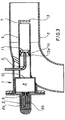
- the execution according to Fig. 3 differs from the execution according to Fig. 1 in that a gas guide device 14 in the form of bores arranged on the circumference of the exhaust pipe 4 and opening approximately in the center of the venturi device 12a is additionally arranged in the region of the venturi device 12a. A partial quantity of process exhaust gas is introduced into the exhaust gas line 4 through this gas guide device 14.
- no venturi device 12b is installed in the region of the mouth 11 in this embodiment.
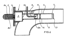
- the execution according to Fig. 4 differs from the execution according to Fig. 2 in that the gas guiding device 14 is incorporated into the exhaust pipe 4 in the region downstream of the venturi device 1 2a.
- Catalyst A (according to the invention):
- Diesel oxidation catalyst with 2.12 g / L (60 g / ft 3 ) Pd on cordierite substrate with dimensions D9.5 "xL4.5", cell density 300 cpsi and wall thickness 5 mil.
- the catalyst was produced by impregnation an aluminum oxide (BET surface area 160 m 2 / g) with palladium nitrate solution and application of the impregnated oxide with a load of 130 g / L to the substrate and subsequent drying and tempering. The catalyst was then aged in the oven in air at 700 ° C. for 16 hours.
- Catalyst B (according to the invention):
- CDPF Catalytically coated filter
- the catalyst was produced by impregnating an aluminosilicate (BET surface area 150 m 2 / g, 5% SiO 2 ) with palladium and platinum nitrate solution and applying the impregnated oxide with a load of 130 g / L to the substrate and subsequent drying and tempering. The catalyst was then aged in the oven in air at 700 ° C. for 16 hours.
- BET surface area 150 m 2 / g, 5% SiO 2 palladium and platinum nitrate solution
- Catalyst D (according to the invention):
- the catalyst was produced by impregnating an aluminosilicate (BET surface area 150 m 2 / g, 5% SiO 2 ) with palladium and platinum nitrate solution and applying the impregnated oxide with a load of 130 g / L to the substrate and subsequent drying and tempering. The catalyst was then aged in the oven in air at 700 ° C. for 16 hours.
- BET surface area 150 m 2 / g, 5% SiO 2 palladium and platinum nitrate solution
- Catalyst E (not according to the invention):
- the catalyst was produced by impregnating an aluminosilicate (BET surface area 150 m 2 / g, 5% SiO 2 ) with palladium and platinum nitrate solution and applying the impregnated oxide with a load of 130 g / L to the substrate and subsequent drying and tempering. The catalyst was then aged in the oven in air at 700 ° C. for 16 hours.
- BET surface area 150 m 2 / g, 5% SiO 2 palladium and platinum nitrate solution
- the desired engine operating point (EOP) is set and the burner switched on with 10 kW output.
- the exhaust gas mass flow MFR results.
- secondary diesel fuel is injected into the flame of the burner in an amount to reach a target temperature of 650 ° C under adiabatic conditions with complete combustion.
- the metering is kept constant for 8 minutes and then switched off again.
- the temperatures before, after and in the catalyst as well as the amount of HC after catalyst HC_out are recorded.
- a new engine operating point is started with the burner switched on.
- a corresponding amount of diesel fuel is metered into the burner flame again and the measurement is carried out. This is repeated for every further operating point.
- Results indicate the results for the different catalysts) EOP MFR T5.0 HC_out ⁇ T5.xi ⁇ T5.xi min -1 Nm Kg / h ° C [ppm C3] [° C] [° C] A B C. D E A B C. D E A B C.
- the catalysts according to the invention alone show satisfactory performance at equivalent or lower costs compared to the variants not according to the invention.
- Catalyst B takes on a separate position due to the integrated filter function and the significantly reduced load.
- the lower loading as well as the higher thermal mass and smaller surface of the Filter substrates cause the combustion to start poorly and run more inhomogeneously within the monitored entry area. This means that the average temperature reached at T5.xi in the inlet is significantly lower in comparison and the standard deviation is higher.
- the target temperature of 600 or 650 ° C is already reached in the front part of the filter.
Landscapes
- Engineering & Computer Science (AREA)
- Chemical & Material Sciences (AREA)
- Combustion & Propulsion (AREA)
- Mechanical Engineering (AREA)
- General Engineering & Computer Science (AREA)
- Chemical Kinetics & Catalysis (AREA)
- Materials Engineering (AREA)
- Health & Medical Sciences (AREA)
- Toxicology (AREA)
- Exhaust Gas After Treatment (AREA)
- Exhaust Gas Treatment By Means Of Catalyst (AREA)
Description
- Die Erfindung betrifft ein Abgasnachbehandlungssystem für eine Brennkraftmaschine. Insbesondere beinhaltet sie eine Einbringungsvorrichtung zur Einbringung von Kohlenwasserstoffen (HCs) in ein das Prozessabgas der Brennkraftmaschine führendes Abgasrohr und eine stromabwärts des Einbringungsortes von Prozessabgas durchströmte und durch Oxidation der eingebrachten Kohlenwasserstoffe die Prozessabgastemperatur erhöhende Behandlungsvorrichtung.
- Ein derartiges Abgasnachbehandlungssystem ist aus der
EP1537304 bekannt. Dieses Abgasnachbehandlungssystem ist zur Anbindung an Kompressionszündungsmotoren, wie Dieselmotoren, ausgelegt. Dabei beschäftigt sich der Gegenstand dieses Dokuments damit, die Gesamtemissionen eines solchen Kompressionszündungsmotors zu verringern. Dazu wird vorgeschlagen, den Kompressionszündungsmotor in verschiedenen Betriebsarten zu betreiben und eine katalytische Komponente aus einer vorgegebenen Auswahl in dem Abgassystem vorzusehen, die zumindest einen Platinkatalysator aufweist. Es ist allgemein bekannt, dass zur Erzeugung bestimmter vorgegebener katalytischer Reaktionen Platinkatalysatoren eingesetzt werden können. - Allgemein ist bekannt, übliche thermische Regenerationssysteme für Partikelfilter zum Beispiel katalytische Brenner zu nutzen. Hierbei wird meist eine flüssige HC-Dosierung in das Abgas zusammen mit einem Dieseloxidationskatalysator, der diese Kohlenwasserstoffe umsetzt und thermische Energie zur Abgastemperaturanhebung auf zirka 600° liefert, eingesetzt. Bevorzugt wird der Kraftstoff in die Abgasleitung zwischen Brennkraftmaschine und Katalysator eingespritzt. Bei PKW-Anwendungen werden die Kohlenwasserstoffe üblicherweise über eine späte, nicht mehr thermisch umgesetzte Nacheinspritzung in den Brennraum der Brennkraftmaschine bereitgestellt. All diese Systeme nutzen Katalysatoren, die in erheblichem Maße Platin beinhalten. Darüber hinaus kommt auch das wesentlich preisgünstigere Palladium zum Einsatz - vorwiegend zur thermischen Stabilisierung des Katalysators - jedoch mit einem Massenanteil von maximal zirka 50 % am Gesamtedelmetall.
- Aus der
EP1857648 ist zu entnehmen, dass ein so genannter "fuel processor" zur Erzeugung von Hitze im Abgasstrang eines Dieselmotors herangezogen werden kann. Dabei kann diese Behandlungsvorrichtung aus einem Oxidationskatalysator und einem Reformierungskatalysator bestehen, welche in das Abgas eingebrachten Kraftstoff ggf. zur Erwärmung einer nachgeordneten Partikelfalle nutzen kann. - Die
US7032376 beschreibt ein Abgasreinigungssystem bestehend aus bestimmten katalytischen Einheiten und einem stromauf befindlichen Brenner, der eine für die katalytischen Einheiten notwendige Wärme generiert. - Aus der
US2008127638 ist zu entnehmen, dass katalytische Einheiten zur Oxidation von Kohlenwasserstoffen bevorzugt aus Pt-only Katalysatoren bestehen und nur ausnahmsweise auch Palladium enthalten können. - Der vorliegenden Erfindung liegt die Aufgabe zugrunde, ein Abgasnachbehandlungssystem und ein Verfahren zum Betreiben eines derartigen Abgasnachbehandlungssystems anzugeben, welches im Stande ist, das Abgas einer Brennkraftmaschine zu erhitzen und darüber hinaus kostengünstig realisierbar ist.
- Diese und weitere hier nicht näher genannte, sich jedoch aus dem Stand der Technik in nahe liegender Weise ergebende Aufgaben werden durch die Angabe eines Abgasnachbehandlungssystems für eine Brennkraftmaschine gelöst, welche eine Vorrichtung zur Einbringung von Kohlenwasserstoffen in ein das Prozessabgas der Brennkraftmaschine führendes Abgasrohr (6) beinhaltet, wobei die Kohlenwasserstoffe in der Vorrichtung zumindest teilweise verdampft sowie durch Crackreaktionen und/oder durch partielle Oxidation chemisch verändert werden und wobei die Vorrichtung zur zumindest teilweisen Verdampfung sowie zur durch Crackreaktionen und/oder durch partielle Oxidation bewirkten chemischen Veränderung der Kohlenwasserstoffe eine Anordnung ist, die einen Brenner (2) mit einer Versorgungsvorrichtung (8a, 8b) für Brennstoff und Luft, sowie eine Brennkammer (3) und eine mit einer Eindüsvorrichtung (5) für Kohlenwasserstoffe versehene Abgasleitung (4) aufweist, die an dem Einbringungsort in das Abgasrohr (6) einmündet, und eine stromabwärts des Austritts (7), vom Prozessabgas durchströmte und durch Oxidation der eingebrachten, teilweise verdampften sowie durch Crackreaktionen und/oder durch partielle Oxidation chemisch veränderten Kohlenwasserstoffe die Prozessabgastemperatur erhöhende, katalytisch beschichtete Bauteile aufweisende Behandlungsvorrichtung beinhaltet, wobei der Platinanteil zumindest in einem Teilbereich der katalytischen Beschichtung der Bauteile weniger als 50 % der Gesamtmasse aller katalytisch wirksamen Substanzen in diesem Teilbereich der Beschichtung beträgt, der Palladiumanteil der katalytischen Beschichtung des Teilbereichs mindestens 50 % der Gesamtmasse aller Edelmetalle des Teilbereichs der Behandlungsvorrichtung beträgt und wobei die katalytisch beschichteten Bauteile Katalysatorsubstrate oder Partikelfilter sind.
- Dieser Ausgestaltung liegt die überraschende Erkenntnis zugrunde, dass ein Abgasnachbehandlungssystem, welches unter Einsatz einer geeigneten Einbringungsvorrichtung die Kohlenwasserstoffe bereits in einer auf besondere Art verdampften sowie durch Crackreaktionen und/oder durch partielle Oxidation chemisch veränderten Form bereitstellt, mit erheblich geringerem Platingehalt in den katalytischen Bestandteilen der nachfolgenden Behandlungsvorrichtung arbeiten kann als dies bei herkömmlichen Kohlenwasserstoffgemischen der Fall ist. Ein Ziel der Einbringung der Kohlenwasserstoffe und Konversion in der Behandlungsvorrichtung ist es dabei, die in einem Partikelfilter aus dem Prozessabgas der Brennkraftmaschine ausgefilterten Rußpartikel kontinuierlich oder diskontinuierlich zu verbrennen. Dass dies mit der erfindungsgemäßen Vorrichtung so überaus erfolgreich und trotzdem kostengünstig umgesetzt werden kann, war so nicht vorhersehbar.
- Innerhalb des Abgasnachbehandlungssystems umfasst der Teilbereich der katalytischen Beschichtung der Bauteile der Behandlungsvorrichtung mindestens 20%, vorzugsweise 30%, weiter vorzugsweise 50% und besonders bevorzugt 100%, der Gesamtmasse der katalytischen Beschichtung auf den Bauteilen der die Prozessabgastemperatur erhöhenden Behandlungsvorrichtung. Unter der katalytischen Beschichtung der Bauteilen werden solche Beschichtungen verstanden, die einen Gradienten von größer +1 K/cm, bevorzugt größer +2.5 K/cm und besonders bevorzugt größer +10 K/cm entlang der Strömungsrichtung während der Phase des Aufheizens des Abgases aufweisen. Dadurch ist eine zuverlässige Funktion des Systems sichergestellt.
- Im Teilbereich der katalytischen Beschichtung der Behandlungsvorrichtung befinden sich weitere katalytisch wirksame Substanzen, insbesondere kann Palladium vorhanden sein. Bevorzugt enthält die katalytische Beschichtung des Teilbereichs Edelmetalle mit einer Gesamtedelmetallmasse bezogen auf das Bauteil- bzw. Substratvolumen im Bereich von 0,1-10 g/L, bevorzugt 0,5-5 g/L und besonders bevorzugt im Bereich von 0,7-3,5 g/L.
- In einer besonders vorteilhaften Ausgestaltung ist es vorgesehen und möglich, dass der Edelmetallanteil der katalytischen Beschichtung des Teilbereichs der Behandlungsvorrichtung weniger als 10%, bevorzugt weniger als 5% und besonders bevorzugt weniger als 3 % der Gesamtmasse der katalytischen Beschichtung des betrachteten Teilbereichs beträgt.
- In einer Ausgestaltung enthält der Teilbereich der katalytischen Beschichtung der Behandlungsvorrichtung also weitere katalytisch wirksame Substanzen. In einer bevorzugten Ausführungsform beträgt der Anteil der Edelmetalle an der Gesamtmasse der katalytisch wirksamen Substanzen jedoch mehr als 10%, besonders bevorzugt mehr als 30% und ganz besonders bevorzugt 100%.
- Palladium ist eines der im Teilbereich existierenden Edelmetalle, und der Palladiumanteil der katalytischen Beschichtung des Teilbereichs der Behandlungsvorrichtung ist mindestens 50 %, vorzugsweise mindestens 75 % und besonders bevorzugt 100% der Gesamtmasse aller Edelmetalle des Teilbereichs der Behandlungsvorrichtung betragen.
- Sofern Platin im Teilbereich vorhanden ist, ist davon auszugehen, dass der Platinanteil in dem Teilbereich der katalytischen Beschichtung der Bauteile weniger als 50%, mehr bevorzugt weniger als 30% und ganz besonders bevorzugt weniger als 20% bzw. äußerst bevorzugt weniger als 10% der Gesamtmasse aller katalytisch wirksamen Substanzen in diesem Teilbereich der Beschichtung beträgt. In einer besonderen Ausführung beträgt der Platingehalt weniger als 5%, bevorzugt weniger als 3% und besonders bevorzugt weniger als 1 % der Gesamtmasse aller katalytisch wirksamen Substanzen des Teilbereichs also im Grenzfall 0 %.
- Unter katalytisch wirksamen Substanzen werden im Sinne dieser Erfindung Aktivmetalle verstanden, d.h. Übergangsmetalle der Gruppen VB, VIB, VIIB, VIII, IB und IIB und insbesondere auch Edelmetalle, welche im Stande sind als Bestandteil einer katalytischen Beschichtung bei einer Aktivmetallkonzentration gewählt im Bereich von 0,1 - 500 g/L Katalysatorraum, bevorzugt 0,2 - 200 g/L und besonders bevorzugt 0,5 - 100 g/L bei einer Temperatur von 350°C ein Kohlenwasserstoffgemisch resultierend aus der Verdampfung von Dieselkraftstoff in Motorabgas mit einer Volumenkonzentration von 1000 ppm C1 zumindest überwiegend zu Kohlendioxid und Wasser zu oxidieren. Die katalytisch wirksamen Substanzen bzw. die Aktivmetalle können in elementarer Form und/oder in Form von Verbindungen, insbesondere Oxiden vorliegen.
- Neben den eingangs angesprochenen katalytisch wirksamen Substanzen, bzw. Aktivmetallen kann die katalytische Beschichtung der Behandlungsvorrichtung weitere Komponenten enthalten, die beispielsweise die feine Verteilung der katalytisch wirksamen Substanzen bzw. Aktivmetalle fördern und allgemein deren Wirkmechanismus unterstützen oder gar erst ermöglichen. Zu diesen Komponenten zählen insbesondere reine oder gemischte Oxide des Aluminiums, des Siliziums, des Titans, des Zirkons oder der Seltenen Erden, wobei Beimengungen von insbesondere Alkali- bzw. Erdalkalielementen, Halogeniden und/oder Schwefel- bzw. Phosphorverbindungen deren Eigenschaften wie z.B. die Azidität weiter modifizieren können. Weitere Beimengungen sind prinzipiell möglich. Weiter finden häufig Speicherkomponenten wie z.B. Zeolithe und/oder Cer/Zirkon-Mischoxide Einsatz. ["Autoabgaskatalysatoren", Hagelüken et. al. , expert Verlag, 2. Auflage, 2005]
- Die katalytisch wirksamen Substanzen sind meist auf diesen weiteren Komponenten oder selektiven Teilen davon angeordnet. Edelmetalle wie z.B. Platin oder Palladium liegen überwiegend in Form von kleinen Partikeln im Bereich von 0,1 bis 100 nm, bevorzugt 0,2-50 nm und weiter bevorzugt 0,5-25 nm Durchmesser vor.
- Die katalytische Beschichtung insgesamt bildet einen hochoberflächigen und hochporösen Aufbau. Typische BET-Oberflächen liegen im Bereich von 1-300 m2/g, vorzugsweise 50-200 m2/g und besonders bevorzugt im Bereich von 80-160 m2/g; Porenvolumina liegen im Bereich von 0,1-2 g/L vorzugsweise 0,2-1,5 g/L und besonders bevorzugt im Bereich von 0,25-1 g/L.
- Die katalytische Beschichtung wird im Allgemeinen in Form eines Schlickers ["Autoabgaskatalysatoren", Hagelüken et. al. , expert Verlag, 2. Auflage, 2005] auf das zu beschichtende Bauteil in einem oder mehreren Schritten aufgetragen. In Einzelfällen können auch Lösungen oder Gasphasenverfahren eingesetzt werden. Häufig werden keramische oder metallische Substrate in Form von Wabenkörpern oder anderen Strukturierungen wie z.B. Schäumen, Wellmatten oder Vliesen beschichtet, prinzipiell sind aber auch glatte Bauteile wie z.B. Rohrinnenwände beschichtbar. Bei den Substraten kann es sich um einfache Durchflusssubstrate handeln aber auch um Substrate mit Filterfunktion, in denen das zu filtrierende Medium z.B. durch eine poröse keramische Wand oder ein Metallvlies geleitet wird.
- Die Funktion der katalytischen Beschichtung besteht darin, die eindosierten oxidierbaren Komponenten, insbesondere Kohlenwasserstoffe (HCs), im Zuflussgas möglichst weitgehend zu Kohlendioxid und Wasser umzusetzen und dabei Wärme zu generieren. Teile dieser Komponenten aus dem Zuflussgas können intermediär in adsorbierter oder flüssiger Form in der Beschichtung gespeichert werden, wobei besonders funktionsfähige Beschichtungen sich darin auszeichnen, dass die Funktionsfähigkeit durch solche Speichereffekte möglichst wenig beeinträchtigt wird. In der Anwendung sind besonders funktionsfähige katalytische Beschichtungen durch geringe Kohlenwasserstoffkonzentrationen am Austritt und geringe radiale Temperaturabweichungen insbesondere im Eintrittsbereich des die Temperatur erhöhenden Teilbereichs der Behandlungsvorrichtung gekennzeichnet, wobei diese Eigenschaften über das komplette Regenerationsintervall von typischerweise ca. 10 bis 20 Minuten möglichst konstant aufrecht erhalten werden.
- Die katalytische Beschichtung wird vorzugsweise in einer Menge von 5-300 g/L, vorzugsweise 10-150 g/L und besonders bevorzugt im Bereich von 20-130 g/L Bauteil- bzw. Substratvolumen aufgebracht. Die Beschichtung weist vorzugsweise eine Schichtdicke im Bereich von 5 bis 200 µm, vorzugsweise 10-100 µm und besonders bevorzugt im Bereich von 20-60 µm auf. Wird Edelmetall als Aktivkomponente eingesetzt, liegt die Gesamtedelmetallmasse bezogen auf das Bauteil- bzw. Substratvolumen vorzugsweise im Bereich von 0,1-10 g/L, Unedle Aktivmetalle bzw. katalytisch wirksame Substanzen können deutlich höhere Beladungen aufweisen und im Extremfall die komplette Beschichtung ausmachen.
- Insbesondere, wenn Palladium bei der katalytischen Beschichtung des Teilbereichs der Behandlungsvorrichtung zum Einsatz kommt, kann der Platinmasseanteil der katalytisch wirksamen Substanzen im Grenzfall 0 %, betragen. Dies war zum Zeitpunkt der Erfindung mitnichten zu vermuten. Häufig sind in diesen die Kohlenwasserstoffe oxidierenden Katalysatoren große Anteile an teurem Platin vorhanden.
- Vorteile einer platinfreien Beschichtung sind:
- Der Preis des Palladiums ist im langjährigen Mittel deutlich geringer als der des Platins, Nichtedelmetalle sind nochmals deutlich kostengünstiger.
- Es wird ein System mit sehr geringen NO2-Emissionen realisiert (NO2 ist giftig und immissionsseitig limitiert, im Untertagebetrieb und in Innenräumen sind NO2-bildende Systeme häufig nicht zulässig).
- Überraschenderweise wird trotz der bekannten Schwefelempfindlichkeit des Palladiums eine erhöhte Schwefeltoleranz im Vergleich zu platinhaltigen Beschichtungen erreicht. Palladium und unedle Aktivmetalle haben im Vergleich zu Platin eine deutlich geringere Wirkung auf die Oxidation von SO2 zu SO3, dementsprechend werden die wahrscheinlich für die Schwefel-Vergiftung von Katalysatoren relevanten Sulfate vermutlich in geringerer Menge gebildet.
- Die Erhöhung der Abgastemperatur wird bevorzugt über einen so genannten Dieseloxidationskatalysator bewirkt. Dies bedeutet, dass der Teilbereich der katalytischen Beschichtung der Bauteile der die Prozessabgastemperatur erhöhenden Behandlungsvorrichtung einen Teil oder die Gesamtheit eines derartigen Dieseloxidationskatalysators darstellt. Die Erhöhung der Abgastemperatur kann aber in einer besonderen Ausführungsform auch oder ausschließlich über einen zu regenerierenden Filter erfolgen. Im Grenzfall wird überhaupt kein Dieseloxidationskatalysator benötigt und das Kohlenwasserstoffgemisch wird direkt auf den katalytisch beschichteten Partikelfilter, der in diesem Fall das alleinige katalytisch beschichtete Bauteil der die Prozessabgastemperatur erhöhende Behandlungsvorrichtung darstellt, geleitet. In diesem Fall ist es naturgemäß erstrebenswert, dass möglichst bald nach Eintritt in den Filter ausreichende Temperaturen zur Regeneration erreicht werden.
- Die die Prozessabgastemperatur erhöhenden katalytisch beschichteten Bauteile sind Katalysatorsubstrate oder Partikelfilter, die jeweils einheitlich oder zonal unterschiedlich beschichtet sein können. Es sind auch Beschichtungslösungen mit einer oder mehreren übereinander liegenden, katalytisch aktiven Schichten denkbar. Im Rahmen der Erfindung ist es möglich, beispielsweise einen Dieseloxidationskatalysator oder einen sonstigen Katalysator, der auch andere Aufgaben übernehmen kann, mit der katalytischen Beschichtung als eigenständiges Bauteil auszugestalten und zu verbauen, oder aber den Dieseloxidationskatalysator mit der katalytischen Beschichtung letztendlich in den Partikelfilter zu integrieren. Selbstverständlich sind auch Kombinationslösungen der beiden beschriebenen Ausgestaltungen im Rahmen der Erfindung möglich und vorgesehen.
- In einer Weiterbildung der Erfindung umfasst der Teilbereich der Behandlungsvorrichtung vorzugsweise ein ganzes die Prozessabgastemperatur erhöhendes katalytisch beschichtetes Bauteil oder einen Teil eines solchen Bauteils oder Teile mehrerer solcher Bauteile. Jedes Bauteil kann also mehrere Teilbereiche aufweisen, die unterschiedliche Eigenschaften haben, von denen ein Teilbereich die zuvor angegebenen Eigenschaften besitzt. Dieser Teilbereich muss nicht zwingend der erste Teil des jeweiligen Bauteils sein, sollte aber zumindest in Strömungsrichtung im vorderen Teil einer zonalen Beschichtung eines solchen Bauteils, insbesondere eines Partikelfilters angeordnet sein.
- Die Einbringungsvorrichtung zur zumindest teilweisen Verdampfung sowie zur durch Crackreaktionen und/oder durch partielle Oxidation bewirkten chemischen Veränderungen der Kohlenwasserstoffe ist in einer weiteren Ausgestaltung eine Anordnung, die einen Brenner mit einer Versorgungsvorrichtung für Brennstoff und Luft sowie eine Brennkammer und eine mit einer Eindüsvorrichtung für Kohlenwasserstoffe versehene Abgasleitung aufweist, die an dem Einbringungsort in das Abgasrohr einmündet (
Fig. 2 ). Die eingedüsten Kohlenwasserstoffe liegen in Form von flüssigem Brennstoff vor, der bevorzugt der gleiche Brennstoff, beispielsweise Dieselkraftstoff, ist, der auch mit der Versorgungsvorrichtung des Brenners eingespritzt wird. Grundsätzlich ist es aber möglich, zum Betreiben des Brenners auch einen gasförmigen Brennstoff, beispielsweise Erdgas, zu verwenden. Die getrennte Einbringung des zusätzlichen Brennstoffs über die Eindüsvorrichtung bietet den Vorteil, dass im Gegensatz zum Stand der Technik eine für einen Prozess beispielsweise benötigte Brennstoffmenge nicht mehr insgesamt durch die Versorgungsvorrichtung des Brenners zugeführt werden muss, sondern stromabwärts des Brenners eine Teilmenge des insgesamt benötigten Brennstoffs als "Sekundärbrennstoffmenge" zugeführt wird. Diese Sekundärbrennstoffmenge wird dann letztendlich ganz kontrolliert aufbereitet und/oder verbrannt. Das entsprechende Betreibungsverfahren zeichnet sich vom Grundsatz her dadurch aus, dass der Brenner eine thermische Grundleistung zur Verfügung stellt, deren Untergrenze durch die Bereitstellung einer ausreichenden Energiemenge zur Verdampfung der in die Abgasleitung eingedüsten Brennstoffmenge vorgegeben ist. Diese Ausgestaltung beziehungsweise dieses Verfahren zum Betreiben eines Abgasnachbehandlungssystems ist im Ergebnis deutlich kostengünstiger realisierbar als ein herkömmliches Abgasnachbehandlungssystem. - In Weiterbildung der Erfindung weist eine Mündung (11) der Eindüsvorrichtung (5) in der Abgasleitung (4) eine Zerstäuberdüse, insbesondere eine Druckzerstäuberdüse oder eine Luftstromzerstäuberdüse, auf. Mit der Druckzerstäuberdüse wird der flüssige Brennstoff allein durch den Druck des Brennstoffs zerstäubt. Alternativ kann die Eindüsvorrichtung aber auch als Luftstromzerstäuberdüse ausgestaltet sein. Dabei wird die Luftstromzerstäuberdüse so betrieben, dass der Brennstoff mit einer geringen Luftmenge in die Abgasleitung eingebracht wird. Bei normalem Betrieb einer Luftstromzerstäuberdüse würde beispielsweise 20 L/min Luft und 2 cm3/min Brennstoff zur Bereitstellung eines zündfähigen Brennstoff-Luft-Gemisches gefördert werden, während mit der erfindungsgemäß betriebenen Luftstromzerstäuber düse mit 20 L/min Luft bis zu 100 cm3/min. Brennstoff zerstäubt werden. Ein derartig fettes Brennstoff-Luft-Gemisch ist primär nicht zündfähig.
- In weiterer Ausgestaltung ist in der Abgasleitung im Bereich einer Mündung der Eindüsvorrichtung eine Venturieinrichtung angeordnet. Diese bewirkt eine schnelle Vermischung der aufeinander treffenden Teilströme von Abgas und verdampftem Brennstoff.
- In weiterer Ausgestaltung der Erfindung sind der Brenner mit der Brennkammer, die Abgasleitung und die Eindüsvorrichtung in ein Gehäuse integriert und das Gehäuse ist an das Abgasrohr adaptiert. Es wird somit eine Baueinheit bereitgestellt, die an verschiedene Abgasrohre angebaut werden kann. Dabei kann das Gehäuse im Idealfall so ausgestaltet sein, dass dieses bei Anwendung an einer Brennkraftmaschine bevorzugt brennkraftmaschinennah, beispielsweise direkt hinter der Abgassammelleitung oder einem Abgasturbolader der Brennkraftmaschine, an das Abgassystem angebaut werden kann.
- In weiterer Ausgestaltung ragt die Abgasleitung mit zumindest einem Austritt in das Abgasrohr hinein. Dadurch wird eine gute Vermischung der zusammentreffenden Gasströme gewährleistet. Dazu ist die Abgasleitung bevorzugt konzentrisch in das Abgasrohr so eingeführt, dass der Austritt aus der Abgasleitung in Strömungsrichtung des Prozessabgasstroms, also beispielsweise des Brennkraftmaschinenabgasstroms, angeordnet ist. Dadurch wird eine Erhöhung der Strömungsgeschwindigkeit des Prozessabgases erreicht, was für eine schnelle Durchmischung des Gasgemischs aus Brennerabgas und verdampften Brennstoff mit dem Prozessabgas sorgt. Dadurch kann eine Entzündung des Gasgemischs auch dann verhindert werden, wenn das Prozessabgas Sauerstoff enthält. Um das Auftreten chemischer Reaktionen im Bereich der Einleitung weiter zu unterbinden, können entsprechende Hilfsmittel, die dies unterstützen, vorgesehen sein. Solche mögliche Hilfsmittel sind beispielsweise eine Platte oder ein Kegel, die vor dem Austritt der Abgasleitung angeordnet sind, wobei die Kegelspitze zu dem Austritt der Abgasleitung hin ausgerichtet ist. Auch ist es vorgesehen, zusätzlich oder alternativ zur weiteren Erhöhung der Strömungsgeschwindigkeit im Bereich des Austritts eine Strömungsverengung in dem Abgasrohr beispielsweise in Form einer Venturieinrichtung oder Venturidüse vorzusehen. Mit anderen Worten soll eine mögliche Reaktion des mit verdampftem Brennstoff aufbereiteten Brennerabgases mit dem Prozessabgas gequencht werden.
- In Weiterbildung der Erfindung mündet in die Abgasleitung eine Prozessabgas führende Gasleitvorrichtung ein. Dadurch wird dem Brennerabgas und dem verdampfenden Brennstoff Prozessabgas zugeführt. Dadurch wird das Brennerabgas (bei einer Zuführung in Strömungsrichtung Eindüsvorrichtung) kontrolliert abgekühlt, und zwar in der Form, dass noch genügend Leistung zum Verdampfen des eingedüsten Brennstoffs bereitgestellt wird, aber dessen Entzündung verhindert wird. Die Zuführung kann aber auch im Bereich der Eindüsvorrichtung oder in Strömungsrichtung dahinter erfolgen. Durch geeignete Wahl der beschriebenen Hilfsmittel können die chemischen Reaktionen des Brennstoffs mit dem Brennerabgas und/oder dem Prozessabgas je nach Bedarf gefördert oder verhindert werden. Insbesondere durch Beeinflussung der Temperatur im Bereich der Eindüsvorrichtung ist es möglich, durch Reaktionen des eingedüsten Brennstoffs mit dem Brennerabgas gezielt Stoffe zu erzeugen, die in dem nachfolgenden Dieseloxidationskatalysator gewünschte Reaktionen unterstützen.
- Die zuvor beschriebenen konstruktiven Ausgestaltungen werden zur Umsetzung der nachfolgend beschriebenen weiteren Ausgestaltung des erfindungsgemäßen Betreibungsverfahrens sinnvoll eingesetzt.
- Bei dem Verfahren zum Betreiben eines erfindungsgemäßen Abgasnachbehandlungssystems für eine Brennkraftmaschine werden die eingedüsten Kohlenwasserstoffe in der Vorrichtung zumindest teilweise verdampft sowie durch Crackreaktionen und/oder durch partielle Oxidation chemisch verändert, wobei ein Brenner (2) als Bestandteil der Vorrichtung eine thermische Grundleistung zur Verfügung stellt, deren Untergrenze durch die Bereitstellung einer ausreichenden Energiemenge zur Verdampfung einer über eine Eindüsvorrichtung (5) in eine Abgasleitung (4) des Brenners (2) eingebrachten Kohlenwasserstoffmenge vorgegeben ist.
- Bevorzugt ist eine katalytisch wirkende Beschichtung zumindest in einem Teilbereich der oxidierend wirkenden Behandlungsvorrichtung angeordnet, wobei der Platinanteil zumindest in einem Teilbereich der katalytischen Beschichtung der Bauteile weniger als 50 % der Gesamtmasse aller katalytisch wirksamen Substanzen in diesem Teilbereich der Beschichtung beträgt. Weiter bevorzugt erbringt der Brenner (2) eine zusätzlich das Prozessabgas auf eine vorgegebene Temperatur aufheizende thermische Leistung.
- So kann der Brenner in einem Lambda-Bereich von 0,75 bis 1,75, bevorzugt von 0,9 bis 1,1, betrieben werden. Weiterhin ist der Brenner so ausgelegt, dass er in einem Leistungsbereich einsetzbar ist, der etwa 1-25%, vorzugsweise 2 - 20% und besonders bevorzugt 2,5 - 15% der Nennmotorleistung entspricht. Es ist ein Ziel der Erfindung, den Brenner mit einer möglichst geringen Leistung zu betreiben, weil dann insbesondere die erforderliche Luftfördereinrichtung für die Zufuhr von (Verbrennungs-) Luft relativ einfach ausgestaltet sein kann.
- Weiterhin wird durch das erfindungsgemäße Verfahren in einer allgemeinen Form der eingedüste Brennstoff (gegebenenfalls unter direkter Hinzufügung einer Teilmenge von Prozessabgas) durch das Brennerabgas verdampft und zusammen mit dem Brennerabgas und der Gesamtmenge des Prozessabgases in die Abgasnachbehandlungseinrichtung geleitet, um die dort vorgesehenen Reaktionen hervorzurufen. Dabei wird der eingedüste Brennstoff zusammen mit dem Brennerabgas und dem Prozessabgas über das Abgasrohr dem Katalysator, insbesondere einem Dieseloxidationskatalysator und einem nachfolgenden Partikelfilter zugeführt und in dem Katalysator (Dieseloxidationskatalysator) und/oder in dem gegebenenfalls zusätzlich noch katalytisch beschichteten Partikelfilter oxidiert. Ein besonderer Vorteil dieser Ausgestaltung ist es, dass die Oxidationsreaktion also erst in dem Katalysator (Dieseloxidationskatalysator) erfolgt und demzufolge erst hier die zur Regeneration des Partikelfilters notwendigen Temperaturen erzeugt werden. Würde der eingespritzte Brennstoff bereits am Ort der Einbringung in die Abgasleitung entzündet, wäre dies mit einer höheren thermischen Belastung des gesamten Abgassystems verbunden und es müssten beträchtliche Wärmeverluste durch größere Kraftstoffmengen ausgeglichen werden.
- Der entscheidende Vorteil des vorgeschlagenen Systems ist es, dass die durch Verdampfung und/oder chemische Modifikation veränderten Kohlenwasserstoffe im Katalysator (Dieseloxidationskatalysator) beziehungsweise in dem beschichteten Partikelfilter oder deren Kombination chemische Reaktionen eingehen, die sich von denen herkömmlicher Systeme zumindest teilweise unterscheiden. Das ist der Grund für den erfindungsgemäß möglichen Ersatz von Platin durch Palladium.
- In dem Katalysator (Dieseloxidationskatalysator) beziehungsweise in dem beschichteten Partikelfilter oder deren Kombination wird durch die Oxidation des eingedüsten Brennstoffs beispielsweise eine Temperatur von bis zu 650°C erzeugt, die zur Regeneration von Partikelfiltern benötigt wird. In weiterer Ausgestaltung des Verfahrens wird eine Teilmenge der eingedüsten Brennstoffmenge unter Freisetzung von Wärme innerhalb der Abgasleitung und/oder dem Ort der Zusammenführung mit dem Prozessabgas oxidiert. Dadurch kann die thermische Gesamtleistung bei minimal eingestellter Brennerleistung so weit erhöht werden, dass eine sichere Inbetriebsetzung des Katalysators (Dieseloxidationskatalysators) beziehungsweise des beschichteten Partikelfilters oder deren Kombination erfolgt. Um seine Aktivität zu starten, also um eine katalytische Reaktion des eingebrachten verdampften Brennstoffs zu starten, muss der Katalysator (Dieseloxidationskatalysator) beziehungsweise der beschichtete Partikelfilter oder deren Kombination eine vorgegebene Mindesttemperatur, beispielsweise 300 °C, erreichen. Diese Temperatur wird durch die Summation der Brennerleistung und der Leistung, die durch die verbrannte Teilmenge erzeugt wird, erreicht.
- In weiterer Ausgestaltung wird die oxidierte Teilmenge der eingedüsten Brennstoffmenge unabhängig von der gesamten eingedüsten Brennstoffmenge zumindest angenähert konstant gehalten. Dabei ist es weiterhin vorgesehen, nach Überschreitung einer Grenzmenge der teilumgesetzten Brennstoffmenge die Teilumsetzung zu beenden und den Brennstoff insgesamt zu verdampfen. Diese unterschiedlichen Wirkungen werden durch eine strikte Kontrolle des Verbrennungsluftverhältnisses in dem Brenner und/oder eine strikte Kontrolle der Menge der im Fall der Verwendung einer Luftstromzerstäuberdüse zugeführten Zerstäubungsluft für die Luftstromzerstäuberdüse erreicht. Weitere Einflussgrößen sind der Ort der Anbringung der Mündung der Eindüsvorrichtung und die Zufuhr einer Teilmenge von Prozessabgas (zur Kühlung des Brennerabgases und folglich der Verdampfflüssigkeit), ebenfalls unter Berücksichtigung des Zufuhrortes.
- Weitere vorteilhafte Ausgestaltungen der Erfindung sind der Zeichnungsbeschreibung zu entnehmen, in der in den Figuren dargestellte Ausführungsbeispiele der Erfindung näher beschrieben sind. Es zeigen:
-
Fig.1 in schematischer Darstellung eine Gesamtdarstellung des Abgasnachbehandlungssystems für eine Brennkraftmaschine, -
Fig. 2 eine erste Ausführung der mit einem Abgasrohr zusammenwirkenden Verdampfereinrichtung, -
Fig. 3 eine zweite Ausführung der mit einem Abgasrohr zusammenwirkenden Verdampfereinrichtung und -
Fig. 4 eine dritte Ausführung der mit einem Abgasrohr zusammenwirkenden Verdampfereinrichtung. - Das in
Figur 1 dargestellte System weist eine Brennkraftmaschine 17 auf, die insbesondere eine Diesel-Brennkraftmaschine ist. Der Brennkraftmaschine 17 wird Dieselkraftstoff und Luft zugeführt, die in den dargestellten vier Zylindern 18 verbrannt werden und über die vor die in den Zylindern beweglichen Kolben und Pleuel die Kurbelwelle in Drehbewegung setzen. Die in den Zylindern 18 verbrannten Abgase werden über ein Sammelrohr 19 in ein Abgasrohr 6 geleitet. In das Abgasrohr 6 ragt eine Abgasleitung 4 eines Brenners 2 hinein, wobei in die Abgasleitung 4 eine Eindüsvorrichtung 5 hineinragt. Dem Brenner 2 wird - wie nachfolgend noch insgesamt erläutert wird - Brennstoff und Luft zugeführt, während über die Eindüsvorrichtung 5 flüssiger Brennstoff in die Abgasleitung 4 eingedüst wird. Das System, bestehend aus dem Brenner 2, der Eindüsvorrichtung 5 und der Abgasleitung 4, wird nachfolgend Verdampfereinrichtung genannt. In das Abgasrohr 6 sind stromabwärts der Einmündung der Abgasleitung 4 ein Dieseloxidationskatalysator 15 und ein Partikelfilter 16 eingebaut. Die in dem Partikelfilter 16 insbesondere aus dem Prozessabgas der Brennkraftmaschine 17 ausgefilterten Rußpartikel werden mit Hilfe der in dem Abgasnachbehandlungssystem erzeugten Wärme verbrannt. - Die Verdampfereinrichtung gemäß
Figur 2 bis 4 weist bei allen Ausführungen ein Gehäuse 1 auf, in das der Brenner 2, eine Brennkammer 3, die Abgasleitung 4 und die Eindüsvorrichtung 5 für einen flüssigen Brennstoff integriert sind. Dabei ist das Gehäuse 1 ebenfalls bei allen Ausführungen so mit dem Abgasrohr 6 verbunden, dass die Abgasleitung 4 mit einem Austritt 7 konzentrisch in das Abgasrohr 6 eingeführt ist und der Austritt 7 in Strömungsrichtung des durch das Abgasrohr 6 strömenden Prozessabgases angeordnet ist. - Der Brenner 2 weist eine Versorgungsvorrichtung 8a für einen gasförmigen oder flüssigen Brennstoff sowie eine Versorgungsvorrichtung 8b für Luft auf. Der Brennstoff und die Luft werden in geeigneter Weise miteinander gemischt und beispielsweise über eine Luftstromzerstäuberdüse 9 in die Brennkammer 3 eingebracht und das Gemisch wird in der Brennkammer 3 verbrannt. Dazu wird das Gemisch in dem Brenner 2 und/oder der Brennkammer 3 in geeigneter Weise entzündet. Um die Wärmeverluste gering zu halten, ist die Brennkammer 3 möglichst weitgehend isoliert in das Gehäuse 1 eingesetzt. Die Brennkammer 3 weist eine Austrittsöffnung 10 auf, durch die das Brennerabgas in die Abgasleitung 4 eintritt und entlang der Abgasleitung 4 bis zu dem Austritt 7 strömt, um sich dort mit dem in dem Abgasrohr 6 strömenden Prozessabgas, das Brennkraftmaschinenabgas ist, zu vermischen. Das Gemisch aus Brennstoff und Luft ist so eingestellt, dass im Bereich der Austrittsöffnung 10 aus der Brennkammer 3 die Oxidationsreaktionen weitgehend abgeschlossen sind und demzufolge ein erhitzter Abgasstrom in die Abgasleitung 4 einströmt. In die Abgasleitung 4 mündet die Eindüsvorrichtung 5 mit einer Mündung 11 vorzugsweise konzentrisch zu der Abgasleitung 4 ein. Am Ort der Mündung 11 ist eine Zerstäuberdüse angeordnet, mit der der über die Eindüsvorrichtung 5 zugeführte flüssige Brennstoff fein zerstäubt wird. Der so eingebrachte Brennstoff wird folglich erhitzt und verdampft. Im Bereich der Mündung 11 ist eine Venturieinrichtung 12a in die Abgasleitung 4 eingesetzt. Die Venturieinrichtung 12a bewirkt eine zusätzliche Vermischung der Verdampfflüssigkeit mit dem Abgas. Im Bereich des Austritts 7 ist eine Quencheinrichtung 13 angeordnet, die in dem Ausführungsbeispiel als Prallplatte ausgebildet ist und eine Durchmischung des aus dem Austritt 7 ausströmenden, mit der verdampften Verdampfflüssigkeit vermischten Abgases mit dem Prozessabgas bewirkt. Gleichzeitig kann die Quencheinrichtung 13 zur Vermeidung einer Entzündung des hier entstehenden Gesamtgemisches eingesetzt werden. Zu einer Strömungsgeschwindigkeitserhöhung des Prozessgasstroms ist im Bereich des Austritts 7 beziehungsweise der Quencheinrichtung 13 eine Venturieinrichtung 12b in das Abgasrohr 6 eingebaut.
- Das auf die beschriebene Weise gebildete Gesamtgemisch wird dann einer Abgasnachbehandlungseinrichtung zugeführt, die einen Stickstoffoxide selektiv katalytisch reduzierenden Katalysator und/oder NO-Speicherkatalysator und/oder einen Dieseloxidationskatalysator 15 und einen Partikelfilter 16 aufweist.
- Die Ausführung gemäß
Fig. 3 unterscheidet sich von der Ausführung gemäßFig. 1 dadurch, dass hier zusätzlich im Bereich der Venturieinrichtung 12a eine Gasleitvorrichtung 14 in Form von auf den Umfang der Abgasleitung 4 angeordneten und etwa im Zentrum der Venturieinrichtung 12a mündenden Bohrungen angeordnet ist. Durch diese Gasleitvorrichtung 14 wird in die Abgasleitung 4 eine Teilmenge Prozessabgas eingeführt. Im Übrigen ist bei dieser Ausführung im Bereich der Mündung 11 keine Venturieinrichtung 12b eingebaut. - Die Ausführung gemäß
Fig. 4 unterscheidet sich von der Ausführung gemäßFig. 2 dadurch, dass die Gasleitvorrichtung 14 hier im Bereich stromabwärts der Venturieinrichtung 1 2a in die Abgasleitung 4 eingearbeitet ist. -
- 1
- Gehäuse
- 2
- Brenner
- 3
- Brennkammer
- 4
- Abgasleitung
- 5
- Eindüsvorrichtung
- 6
- Abgasrohr
- 7
- Austritt
- 8a, 8b
- Versorgungsvorrichtung
- 9
- Luftstromzerstäuberdüse
- 10
- Austrittsöffnung
- 11
- Mündung
- 12a, 12b
- Venturieinrichtung
- 13
- Quencheinrichtung
- 14
- Gasleitvorrichtung
- 15
- Dieseloxidationskatalysator
- 16
- Partikelfilter
- 17
- Brennkraftmaschine
- 18
- Zylinder
- 19
- Sammelrohr
- Dieseloxidationskatalysator (DOC) mit 2,12 g/L (60 g/ft3) Pd auf Cordierit Substrat mit den Abmessungen D9.5"xL4.5", der Zelldichte 300 cpsi und der Wandstärke 5 mil. Der Katalysator wurde hergestellt durch Imprägnierung eines Aluminiumoxids (BET-Oberfläche 160 m2/g) mit Palladiumnitratlösung und Aufbringung des imprägnierten Oxids mit einer Beladung von 130 g/L auf das Substrat und anschließender Trocknung und Temperung. Der Katalysator wurde dann 16h bei 700°C im Ofen unter Luft gealtert.
- Katalytisch beschichteter Filter (CDPF) mit insgesamt 0,82 g/L (25 g/ft3) Pd auf einem Cordierit-Oberflächenfiltersubstrat mit den Abmessungen D9.5"xL12", der Zelldichte 200 cpsi und der Wandstärke 12 mil. Der Palladiumgehalt im Bereich 5 Zoll ausgehend vom Eintritt beträgt 1,63 g/L (46 g/ft3), im restlichen Bereich 0,35 g/L (10 g/ft3).
- DOC mit 1,41 g/L (40 g/ft3) Masseanteil Pt:Pd von 1:4 auf Cordierit Substrat mit den Abmessungen D9.5"xL4.5", der Zelldichte 300 cpsi und der Wandstärke 5 mil. Der Katalysator wurde hergestellt durch Imprägnierung eines Alumosilikats (BET-Oberfläche 150 m2/g, 5% SiO2) mit Palladium- und Platinnitratlösung und Aufbringung des imprägnierten Oxids mit einer Beladung von 130 g/L auf das Substrat und anschließender Trocknung und Temperung. Der Katalysator wurde dann 16h bei 700°C im Ofen unter Luft gealtert.
- DOC mit 1,06 g/L (30 g/ft3) Masseanteil Pt:Pd von 1:2 auf Cordierit Substrat mit den Abmessungen D9.5"xL4.5", der Zelldichte 300 cpsi und der Wandstärke 5 mil. Der Katalysator wurde hergestellt durch Imprägnierung eines Alumosilikats (BET-Oberfläche 150 m2/g, 5% SiO2) mit Palladium- und Platinnitratlösung und Aufbringung des imprägnierten Oxids mit einer Beladung von 130 g/L auf das Substrat und anschließender Trocknung und Temperung. Der Katalysator wurde dann 16h bei 700°C im Ofen unter Luft gealtert.
- DOC mit 1,06 g/L (30 g/ft3) Masseanteil Pt:Pd von 2:1 auf Cordierit Substrat mit den Abmessungen D9.5"xL4.5", der Zelldichte 300 cpsi und der Wandstärke 5 mil. Der Katalysator wurde hergestellt durch Imprägnierung eines Alumosilikats (BET-Oberfläche 150 m2/g, 5% SiO2) mit Palladium- und Platinnitratlösung und Aufbringung des imprägnierten Oxids mit einer Beladung von 130 g/L auf das Substrat und anschließender Trocknung und Temperung. Der Katalysator wurde dann 16h bei 700°C im Ofen unter Luft gealtert.
- Motor: TCD 2012 L06-4 mit Tier III-Abstimmung von Deutz
Brenner: 10 kW Heizleistung (Dieselkraftstoffversorgung) mit sekundärer Diesel-Eindosierung in die Brennerflamme
Die Katalysatoren sind jeweils mit 10 Thermoelementen T5.1i bis T5.10i bzw. T5.1o bis T5.10o in 1 Zoll Tiefe von der Eintritts- und Austrittsseite des Katalysators bestückt. - Nach 30minütiger Konditionierung des Katalysatorsystems bei Volllast wird der gewünschte Motorbetriebspunkt (EOP) eingestellt und der Brenner mit 10 kW Leistung zugeschaltet. Es ergibt sich der Abgasmassenstrom MFR. Nachdem sich die Temperatur am DOC-Eintritt auf den Zielwert T5.0 eingependelt hat, wird Sekundärdieselkraftstoff in die Flamme des Brenners eingedüst in einer Menge um unter adiabaten Bedingungen bei vollständiger Verbrennung eine Zieltemperatur von 650°C zu erreichen. Die Eindosierung wird über 8 Minuten konstant aufrechterhalten und dann wieder abgestellt. Die Temperaturen vor, nach und im Katalysator sowie die HC-Menge nach Katalysator HC_out werden aufgezeichnet. Anschließend wird ein neuer Motorbetriebspunkt bei eingeschaltetem Brenner angefahren. Nach Stabilisierung der DOC-Eintrittstemperatur wird erneut eine entsprechende Dieselkraftstoffmenge in die Brennerflamme eindosiert und es erfolgt die Vermessung. Dies wird für jeden weiteren Betriebspunkt wiederholt.
- Ergebnisse (A,B,C,D,E) kennzeichnen die Ergebnisse für die unterschiedlichen Katalysatoren)
EOP MFR T5.0 HC_out Ø T5.xi σ T5.xi min-1 Nm Kg/h °C [ppm C3] [°C] [°C] A B C D E A B C D E A B C D E 1910 200 420 300 218 127 247 314 3588* 537 420 531 513 292* 8,2 34 11,7 17,0 4,5* 1635 295 425 320 207 96 221 260 598 570 492 586 573 466 8,5 17 9,8 11,7 73,4 1550 345 430 340 194 103 214 247 495 577 509 590 587 560 7,9 15 9,3 10,4 20,1 1470 390 430 360 179 107 195 226 432 590 525 596 592 587 7,6 14 9,0 10,0 5,5 *) Vollständiger Einbruch der Katalysatoraktivität Katalysator Relative Kosten A 100% C 107% D 100% E 150% - Die relativen Kosten wurden auf Basis des über 5 Jahre gemittelten Preisverhältnisses von Platin zu Palladium von ca. 4 ermittelt. Katalysator B ist nicht vergleichbar, da hier die Filterfunktion mit integriert ist.
- Es ist zu erkennen, dass mit abnehmenden Platinanteil der Schlupf an Kohlenwasserstoffen (HC out) abnimmt und der Mittelwert der Temperaturen im Eintrittsbereich des Katalysators (Ø T5.xi) zunimmt. Dazu wurden die Messwerte der einzelnen Thermoelemente über die letzten 20 s des Regenerationszyklus gemittelt und daraus wiederum der Gesamtmittelwert gebildet. Die Standardabweichung dieser Temperaturmessstellen innerhalb der letzten 20 s des Regenerationszyklus (σ T5.xi) ist bei platinarmen Katalysatoren geringer, was auf eine einheitlichere Verbrennung hinweist. Diese Beobachtungen gelten im besonderen Maße für die niedrigen Eintrittstemperaturen T5.0.
- Allein die erfindungsgemäßen Katalysatoren zeigen befriedigende Leistung bei äquivalenten bzw. geringeren Kosten gegenüber den nichterfindungsgemäßen Varianten.
- Katalysator B übernimmt aufgrund der integrierten Filterfunktion und der deutlich abgesenkten Beladung eine gesonderte Stellung ein. Die geringere Beladung sowie die höhere thermische Masse und geringere Oberfläche des Filtersubstrats führen dazu, dass innerhalb des überwachten Eintrittsbereiches die Verbrennung schlechter anspringt und inhomogener verläuft. Somit ist die erreichte Durchschnittstemperatur Ø T5.xi im Eingang im Vergleich deutlich abgesenkt und die Standardabweichung höher. Die Zieltemperatur von 600 bzw. 650°C wird jedoch bereits im vorderen Teil des Filters erreicht wird.
- Weitere Versuche bei zusätzlicher intensiverer Alterung (16h bei 800°C in 80%N2/10%O2/10%H2O) zeigen, dass diese Differenzierung noch stärker zutage tritt.
Claims (17)
- Abgasnachbehandlungssystem für eine Brennkraftmaschine, beinhaltend:a. eine Vorrichtung zur Einbringung von Kohlenwasserstoffen in ein das Prozessabgas der Brennkraftmaschine führendes Abgasrohr (6), wobei die Kohlenwasserstoffe in der Vorrichtung zumindest teilweise verdampft sowie durch Crackreaktionen und/oder durch partielle Oxidation chemisch verändert werden und wobei die Vorrichtung zur zumindest teilweisen Verdampfung sowie zur durch Crackreaktionen und/oder durch partielle Oxidation bewirkten chemischen Veränderung der Kohlenwasserstoffe eine Anordnung ist, die einen Brenner (2) mit einer Versorgungsvorrichtung (8a, 8b) für Brennstoff und Luft, sowie eine Brennkammer (3) und eine mit einer Eindüsvorrichtung (5) für Kohlenwasserstoffe versehene Abgasleitung (4) aufweist, die an dem Einbringungsort in das Abgasrohr (6) einmündet, undb. eine stromabwärts des Austritts (7), vom Prozessabgas durchströmte und durch Oxidation der eingebrachten, teilweise verdampften sowie durch Crackreaktionen und/oder durch partielle Oxidation chemisch veränderten Kohlenwasserstoffe die Prozessabgastemperatur erhöhende, katalytisch beschichtete Bauteile aufweisende Behandlungsvorrichtung,dadurch gekennzeichnet, dass
der Platinanteil zumindest in einem Teilbereich der katalytischen Beschichtung der Bauteile weniger als 50 % der Gesamtmasse aller katalytisch wirksamen Substanzen in diesem Teilbereich der Beschichtung beträgt, der Palladiumanteil der katalytischen Beschichtung des Teilbereichs mindestens 50 % der Gesamtmasse aller Edelmetalle des Teilbereichs der Behandlungsvorrichtung beträgt und wobei die katalytisch beschichteten Bauteile Katalysatorsubstrate oder Partikelfilter sind. - Abgasnachbehandlungssystem nach Anspruch 1,
dadurch gekennzeichnet, dass
der Teilbereich der katalytischen Beschichtung der Bauteile der Behandlungsvorrichtung mindestens 20% der Gesamtmasse der katalytischen Beschichtung auf den Bauteilen der die Prozessabgastemperatur erhöhenden Behandlungsvorrichtung umfasst. - Abgasnachbehandlungssystem nach Anspruch 1 oder 2,
dadurch gekennzeichnet, dass
die katalytische Beschichtung des Teilbereichs Edelmetalle mit einer Gesamtedelmetallmasse bezogen auf das Bauteil- bzw. Substratvolumen im Bereich von 0,1-10 g/L enthält. - Abgasnachbehandlungssystem nach Anspruch 3, dadurch gekennzeichnet, dass der Anteil der Edelmetalle an der Gesamtmasse aller katalytisch wirksamen Substanzen des Teilbereichs der Behandlungsvorrichtung mehr als 10% beträgt.
- Abgasnachbehandlungssystem nach Anspruch 3 und/oder 4,
dadurch gekennzeichnet, dass
der Platingehalt der katalytischen Beschichtung des Teilbereichs weniger als 1% der Gesamtmasse aller katalytisch wirksamen Substanzen des Teilbereichs der Behandlungsvorrichtung beträgt. - Abgasnachbehandlungssystem nach einem der vorherigen Ansprüche,
dadurch gekennzeichnet, dass
der Teilbereich ein ganzes die Prozessabgastemperatur erhöhendes katalytisch beschichtetes Bauteil oder einen Teil eines solchen Bauteils oder Teile mehrerer solcher Bauteile umfasst. - Abgasnachbehandlungssystem nach einem oder mehreren der Ansprüche 1 bis 6,
dadurch gekennzeichnet, dass
der Teilbereich den in Strömungsrichtung vorderen Teil einer zonalen Beschichtung eines solchen Bauteils darstellt. - Abgasnachbehandlungssystem nach einem oder mehreren der vorhergehenden Ansprüche,
dadurch gekennzeichnet, dass
insbesondere die Mündung (11) der Eindüsvorrichtung (5) in der Abgasleitung (4) eine Zerstäuberdüse, insbesondere eine Druckzerstäuberdüse oder eine Luftstromzerstäuberdüse, aufweist. - Abgasnachbehandlungssystem nach einem oder mehreren der vorhergehenden Ansprüche,
dadurch gekennzeichnet, dass
in der Abgasleitung (4) im Bereich der Mündung (11) der Eindüsvorrichtung (5) eine Venturieinrichtung (12a, 12b) angeordnet ist. - Abgasnachbehandlungssystem nach einem oder mehreren der vorhergehenden Ansprüche,
dadurch gekennzeichnet, dass
der Brenner (2), die Abgasleitung (4) und die Eindüsvorrichtung (5) in ein Gehäuse (1) integriert sind und das Gehäuse (1) an das Abgasrohr (6) adaptiert ist. - Abgasnachbehandlungssystem nach einem oder mehreren der vorhergehenden Ansprüche,
dadurch gekennzeichnet, dass
die Abgasleitung (4) mit einem Austritt (7) in das Abgasrohr (6) hineinragt. - Abgasnachbehandlungssystem nach Anspruch 11,
dadurch gekennzeichnet, dass
die Abgasleitung (4) konzentrisch in das Abgasrohr (6) so eingeführt ist, dass der Austritt (7) aus der Abgasleitung (4) in Strömungsrichtung des Prozessabgasstroms angeordnet ist. - Abgasnachbehandlungssystem nach einem oder mehreren der vorhergehenden Ansprüche,
dadurch gekennzeichnet, dass
im Bereich des Austritts (7) eine Quencheinrichtung (13) und/oder eine Venturieinrichtung vorhanden ist. - Abgasnachbehandlungssystem nach einem oder mehreren der vorhergehenden Ansprüche,
dadurch gekennzeichnet, dass
in die Abgasleitung (4) eine Prozessabgas führende Gasleitvorrichtung (14) vorzugsweise stromaufwärts der Mündung (11) der Einbringvorrichtung einmündet. - Verfahren zum Betreiben eines Abgasnachbehandlungssystems für eine Brennkraftmaschine gemäß einem oder mehreren der Ansprüche 1 bis 14,
dadurch gekennzeichnet, dass
die Kohlenwasserstoffe in der Vorrichtung zumindest teilweise verdampft sowie durch Crackreaktionen und/oder durch partielle Oxidation chemisch verändert werden und dass ein Brenner (2) als Bestandteil der Vorrichtung eine thermische Grundleistung zur Verfügung stellt, deren Untergrenze durch die Bereitstellung einer ausreichenden Energiemenge zur Verdampfung einer über eine Eindüsvorrichtung (5) in eine Abgasleitung (4) des Brenners (2) eingebrachten Kohlenwasserstoffmenge vorgegeben ist. - Verfahren nach Anspruch 15,
dadurch gekennzeichnet, dass
eine katalytisch wirkende Beschichtung zumindest in einem Teilbereich der oxidierend wirkenden Behandlungsvorrichtung angeordnet ist und dass der Platinanteil zumindest in einem Teilbereich der katalytischen Beschichtung der Bauteile weniger als 50% der Gesamtmasse aller katalytisch wirksamen Substanzen in diesem Teilbereich der Beschichtung beträgt. - Verfahren nach Anspruch 15 und/oder 16,
dadurch gekennzeichnet, dass
der Brenner (2) eine zusätzlich das Prozessabgas auf eine vorgegebene Temperatur aufheizende thermische Leistung erbringt.
Applications Claiming Priority (2)
| Application Number | Priority Date | Filing Date | Title |
|---|---|---|---|
| DE102009023550A DE102009023550A1 (de) | 2009-05-30 | 2009-05-30 | Abgasnachbehandlungssystem |
| PCT/EP2010/003260 WO2010139429A1 (de) | 2009-05-30 | 2010-05-28 | Abgasnachbehandlungssystem |
Publications (2)
| Publication Number | Publication Date |
|---|---|
| EP2435672A1 EP2435672A1 (de) | 2012-04-04 |
| EP2435672B1 true EP2435672B1 (de) | 2020-04-29 |
Family
ID=42556425
Family Applications (1)
| Application Number | Title | Priority Date | Filing Date |
|---|---|---|---|
| EP10722319.0A Active EP2435672B1 (de) | 2009-05-30 | 2010-05-28 | Abgasnachbehandlungssystem |
Country Status (8)
| Country | Link |
|---|---|
| US (1) | US8984866B2 (de) |
| EP (1) | EP2435672B1 (de) |
| JP (1) | JP5882201B2 (de) |
| CN (1) | CN102449278B (de) |
| BR (1) | BRPI1011727A2 (de) |
| DE (1) | DE102009023550A1 (de) |
| RU (1) | RU2567331C2 (de) |
| WO (1) | WO2010139429A1 (de) |
Families Citing this family (19)
| Publication number | Priority date | Publication date | Assignee | Title |
|---|---|---|---|---|
| DE102010008999A1 (de) * | 2010-02-24 | 2011-08-25 | J. Eberspächer GmbH & Co. KG, 73730 | Abgasbehandlungseinrichtung |
| DE102010055548A1 (de) * | 2010-12-22 | 2012-06-28 | Deutz Ag | Verbrennungskraftmaschine und Verfahren zum Betreiben derselben |
| EP2653681B2 (de) * | 2012-04-20 | 2019-12-04 | Umicore AG & Co. KG | Verwendung eines Beschichteten Dieselpartikelfilters zum Verhindern der Kontamination eines SCR-Katalysators |
| CN103861396A (zh) * | 2012-12-17 | 2014-06-18 | 北京英泰世纪环境科技有限公司 | 内燃机颗粒物排放后处理净化装置 |
| EP2826971A1 (de) | 2013-07-17 | 2015-01-21 | DEUTZ Aktiengesellschaft | Verfahren zur Verminderung von Stickoxiden in dieselmotorischen Abgasen und Abgasnachbehandlungssystem zur Durchführung des Verfahrens |
| DE102014001880A1 (de) | 2014-02-14 | 2015-08-20 | Deutz Aktiengesellschaft | Verfahren zum Reinigen von Dieselmotorenabgassen |
| DE102014019427A1 (de) | 2014-02-14 | 2015-08-20 | Deutz Aktiengesellschaft | Verfahren zur Reinigung von Dieselmotorenabgasen |
| DE102014001879A1 (de) | 2014-02-14 | 2015-08-20 | Deutz Aktiengesellschaft | Brennkraftmaschine |
| CN104989501B (zh) * | 2015-07-20 | 2017-10-13 | 中国船舶重工集团公司第七一一研究所 | 一种船用scr系统温度补偿装置 |
| US10788000B2 (en) | 2016-03-22 | 2020-09-29 | Cnh Industrial America Llc | System and method for aspirating a pre-cleaner of a work vehicle using a double-walled flow pipe |
| DE102016117746A1 (de) | 2016-09-21 | 2018-03-22 | Eberspächer Exhaust Technology GmbH & Co. KG | Reaktionsmitteleingabeanordnung zur Eingabe von Reaktionsmittel in den Abgasstrom einer Brennkraftmaschine |
| JP2018071360A (ja) * | 2016-10-25 | 2018-05-10 | 株式会社三五 | 排気浄化装置 |
| CN107191251A (zh) * | 2017-05-26 | 2017-09-22 | 凯龙高科技股份有限公司 | 一种满足国六排放的柴油机后处理系统 |
| CN106988839A (zh) * | 2017-05-26 | 2017-07-28 | 凯龙高科技股份有限公司 | 满足在用车NOx和PM排放控制的柴油机后处理系统 |
| DE102018220715A1 (de) | 2018-11-30 | 2020-06-04 | Volkswagen Aktiengesellschaft | Abgasnachbehandlungssystem sowie Verfahren zur Abgasnachbehandlung eines Verbrennungsmotors |
| IT202100017258A1 (it) * | 2021-06-30 | 2022-12-30 | Marelli Europe Spa | Metodo di controllo di un bruciatore per un sistema di scarico di un motore a combustione interna |
| IT202100017255A1 (it) * | 2021-06-30 | 2022-12-30 | Marelli Europe Spa | Metodo di controllo di un bruciatore per un sistema di scarico di un motore a combustione interna |
| US11885251B2 (en) * | 2022-05-25 | 2024-01-30 | Tenneco Automotive Operating Company Inc. | Selective catalytic reduction catalyst pre-heating burner assembly and method of controlling burner emissions |
| CN117780504B (zh) * | 2024-02-26 | 2024-04-26 | 上海浦帮机电制造有限公司 | 一种辅助发动机 |
Citations (1)
| Publication number | Priority date | Publication date | Assignee | Title |
|---|---|---|---|---|
| WO2012084156A1 (de) * | 2010-12-22 | 2012-06-28 | Deutz Aktiengesellschaft | Verbrennungskraftmaschine und verfahren zum betreiben derselben |
Family Cites Families (21)
| Publication number | Priority date | Publication date | Assignee | Title |
|---|---|---|---|---|
| US3739576A (en) * | 1969-08-11 | 1973-06-19 | United Aircraft Corp | Combustion system |
| FR2548264B1 (fr) * | 1983-06-16 | 1985-12-13 | Renault | Regeneration des filtres a particules, notamment pour moteurs diesel |
| DE3837472C2 (de) * | 1988-11-04 | 1998-09-24 | Deutz Ag | Partikelfiltersystem |
| DE4325906C2 (de) * | 1993-08-02 | 1995-08-24 | Daimler Benz Ag | Vorrichtung zur Regenerierung eines im Abgastrakt einer Brennkraftmaschine eingesezten Partikelfilters |
| GB2295561A (en) * | 1994-11-29 | 1996-06-05 | Lucas Ind Plc | Device for delivering gaseous hydrocarbon to an engine exhaust |
| DE19504183A1 (de) * | 1995-02-09 | 1996-08-14 | Eberspaecher J | Brenner zur thermischen Regeneration eines Partikelfilters in einem Abgasnachbehandlungssystem eines Verbrennungsmotors, insbesondere Dieselmotors |
| EP1857648B1 (de) * | 2001-12-03 | 2013-10-23 | International Engine Intellectual Property Company, LLC | System und Verfahren zur Verbesserung der Emissionssteuerung bei Verbrennungsmotoren |
| JP2005538301A (ja) | 2002-09-13 | 2005-12-15 | ジョンソン、マッセイ、パブリック、リミテッド、カンパニー | 圧縮着火機関排ガスの処理方法 |
| US7032376B1 (en) * | 2003-08-27 | 2006-04-25 | Southwest Research Institute | Diesel fuel burner for diesel emissions control system |
| US20060283181A1 (en) * | 2005-06-15 | 2006-12-21 | Arvin Technologies, Inc. | Swirl-stabilized burner for thermal management of exhaust system and associated method |
| DE102004051905A1 (de) * | 2004-10-26 | 2006-04-27 | Robert Bosch Gmbh | Vorrichtung und Verfahren zur Erzeugung eines Betriebsmittels für ein Kraftfahrzeug |
| JP2006242011A (ja) * | 2005-03-01 | 2006-09-14 | Bosch Corp | 排気浄化装置及び排気ガスの浄化方法 |
| DE102005037969A1 (de) * | 2005-08-11 | 2007-02-15 | Deutsches Zentrum für Luft- und Raumfahrt e.V. | Vorrichtung zur Heißgaserzeugung im Abgasstrang eines Verbrennungsmotors |
| JP2007130580A (ja) * | 2005-11-10 | 2007-05-31 | Toyota Motor Corp | 排ガス浄化装置及び排ガス浄化方法 |
| JP4614448B2 (ja) * | 2005-11-25 | 2011-01-19 | ボッシュ株式会社 | 内燃機関の排気浄化装置 |
| KR100756025B1 (ko) * | 2006-08-28 | 2007-09-07 | 희성엥겔하드주식회사 | 내연기관 배기가스 정화용 삼중층 촉매시스템 |
| US20080127638A1 (en) | 2006-12-01 | 2008-06-05 | Marius Vaarkamp | Emission Treatment Systems and Methods |
| KR101051874B1 (ko) * | 2007-01-17 | 2011-07-25 | 나노스텔라 인코포레이티드 | 팔라듐-금을 함유하는 엔진 배기가스 촉매 |
| US9993771B2 (en) * | 2007-12-12 | 2018-06-12 | Basf Corporation | Emission treatment catalysts, systems and methods |
| DE102008026477A1 (de) | 2008-06-03 | 2009-12-10 | Deutz Ag | Abgasnachbehandlungssystem für eine selbstzündende Brennkraftmaschine |
| DE102008063515A1 (de) * | 2008-12-18 | 2010-06-24 | Deutz Ag | Verdampfer |
-
2009
- 2009-05-30 DE DE102009023550A patent/DE102009023550A1/de not_active Withdrawn
-
2010
- 2010-05-28 BR BRPI1011727A patent/BRPI1011727A2/pt not_active Application Discontinuation
- 2010-05-28 JP JP2012513497A patent/JP5882201B2/ja not_active Expired - Fee Related
- 2010-05-28 EP EP10722319.0A patent/EP2435672B1/de active Active
- 2010-05-28 CN CN201080022659.7A patent/CN102449278B/zh not_active Expired - Fee Related
- 2010-05-28 US US13/375,083 patent/US8984866B2/en not_active Expired - Fee Related
- 2010-05-28 RU RU2011153012/06A patent/RU2567331C2/ru not_active IP Right Cessation
- 2010-05-28 WO PCT/EP2010/003260 patent/WO2010139429A1/de not_active Ceased
Patent Citations (1)
| Publication number | Priority date | Publication date | Assignee | Title |
|---|---|---|---|---|
| WO2012084156A1 (de) * | 2010-12-22 | 2012-06-28 | Deutz Aktiengesellschaft | Verbrennungskraftmaschine und verfahren zum betreiben derselben |
Also Published As
| Publication number | Publication date |
|---|---|
| EP2435672A1 (de) | 2012-04-04 |
| WO2010139429A1 (de) | 2010-12-09 |
| BRPI1011727A2 (pt) | 2016-03-22 |
| CN102449278A (zh) | 2012-05-09 |
| JP2012528974A (ja) | 2012-11-15 |
| RU2567331C2 (ru) | 2015-11-10 |
| RU2011153012A (ru) | 2013-12-27 |
| US20120117949A1 (en) | 2012-05-17 |
| US8984866B2 (en) | 2015-03-24 |
| CN102449278B (zh) | 2016-02-10 |
| DE102009023550A1 (de) | 2010-12-09 |
| JP5882201B2 (ja) | 2016-03-09 |
Similar Documents
| Publication | Publication Date | Title |
|---|---|---|
| EP2435672B1 (de) | Abgasnachbehandlungssystem | |
| DE60225321T2 (de) | System und verfahren zur verbesserten emissionskontrolle von brennkraftmaschinen | |
| DE69418168T2 (de) | Abgasreinigung | |
| EP2558691B1 (de) | Reduktionskatalytisch beschichtetes dieselpartikelfilter mit verbesserten eigenschaften | |
| DE602004003354T2 (de) | Einen teilchenfilter und nox-absorber enthaltendes abgassystem für brennkraftmaschine mit magergemischverbrennung | |
| EP2054153B1 (de) | Katalytisch beschichteter dieselpartikelfilter, verfahren zu seiner herstellung und seine verwendung | |
| EP1985819B1 (de) | Abgasnachbehandlungssystem | |
| EP0708230B1 (de) | Einrichtung zum Nachbehandeln von Abgasen einer selbstzündenden Brennkraftmaschine | |
| EP3418518B1 (de) | Abgasnachbehandlungssystem und verfahren zur abgasnachbehandlung eines verbrennungsmotors | |
| EP2368024B1 (de) | Verdampfer | |
| DE112016004452T5 (de) | Benzinpartikelfilter | |
| DE112016000147T5 (de) | Abgassystem für einen dieselmotor | |
| DE112014000482T5 (de) | Abgasreinigungskatalysator und Verfahren zum Herstellen desselben | |
| DE102017122846A1 (de) | NOx-Adsorberkatalysator | |
| DE102010045203A1 (de) | Oxidierender Partikelfilter | |
| DE102005005663A1 (de) | Abgasnachbehandlungseinrichtung mit Partikelfilter | |
| EP0806553A2 (de) | Verfahren zur Abgasreinigung bei Dieselmotoren | |
| DE102011013183A1 (de) | Lachgasoptimiertes Abgasnachbehandlungssystem einer Kraftfahrzeug-Brennkraftmaschine und Betriebsverfahren hierfür | |
| EP2382041B1 (de) | Vanadiumfreier diesel-oxidationskatalysator und vefahren zu dessen herstellung | |
| DE10242303A1 (de) | Abgasreinigungsanlage und Verfahren zur Reinigung von Absagen | |
| DE102017201401B4 (de) | Abgasnachbehandlung | |
| WO2002048512A1 (de) | Abgasreinigungsanlage und verfahren zur abgasreinigung | |
| WO2006125525A1 (de) | Abgasanlage für eine verbrennungskraftmaschine | |
| DE19617563C1 (de) | Abgaskatalysatoranlage für einen Dieselmotor | |
| DE102006051790A1 (de) | Abgasnachbehandlungssystem eines Verbrennungsmotors |
Legal Events
| Date | Code | Title | Description |
|---|---|---|---|
| PUAI | Public reference made under article 153(3) epc to a published international application that has entered the european phase |
Free format text: ORIGINAL CODE: 0009012 |
|
| 17P | Request for examination filed |
Effective date: 20111230 |
|
| AK | Designated contracting states |
Kind code of ref document: A1 Designated state(s): AL AT BE BG CH CY CZ DE DK EE ES FI FR GB GR HR HU IE IS IT LI LT LU LV MC MK MT NL NO PL PT RO SE SI SK SM TR |
|
| DAX | Request for extension of the european patent (deleted) | ||
| 17Q | First examination report despatched |
Effective date: 20140106 |
|
| STAA | Information on the status of an ep patent application or granted ep patent |
Free format text: STATUS: EXAMINATION IS IN PROGRESS |
|
| REG | Reference to a national code |
Ref country code: DE Ref legal event code: R079 Ref document number: 502010016610 Country of ref document: DE Free format text: PREVIOUS MAIN CLASS: F01N0003023000 Ipc: F01N0003100000 |
|
| GRAP | Despatch of communication of intention to grant a patent |
Free format text: ORIGINAL CODE: EPIDOSNIGR1 |
|
| STAA | Information on the status of an ep patent application or granted ep patent |
Free format text: STATUS: GRANT OF PATENT IS INTENDED |
|
| RIC1 | Information provided on ipc code assigned before grant |
Ipc: F01N 3/20 20060101ALI20190912BHEP Ipc: F01N 3/10 20060101AFI20190912BHEP Ipc: F01N 3/023 20060101ALI20190912BHEP |
|
| INTG | Intention to grant announced |
Effective date: 20191008 |
|
| RIN1 | Information on inventor provided before grant (corrected) |
Inventor name: GEISSELMANN, ANDREAS Inventor name: SCHRAML, STEPHAN Inventor name: WOERZ, ANKE Inventor name: MIEBACH, ROLF Inventor name: DE BUHR, STEFAN Inventor name: SCHUETZE, FRANK-WALTER Inventor name: BROLL, PETER Inventor name: FRANTZ, STEPHANIE |
|
| GRAS | Grant fee paid |
Free format text: ORIGINAL CODE: EPIDOSNIGR3 |
|
| GRAA | (expected) grant |
Free format text: ORIGINAL CODE: 0009210 |
|
| STAA | Information on the status of an ep patent application or granted ep patent |
Free format text: STATUS: THE PATENT HAS BEEN GRANTED |
|
| AK | Designated contracting states |
Kind code of ref document: B1 Designated state(s): AL AT BE BG CH CY CZ DE DK EE ES FI FR GB GR HR HU IE IS IT LI LT LU LV MC MK MT NL NO PL PT RO SE SI SK SM TR |
|
| REG | Reference to a national code |
Ref country code: GB Ref legal event code: FG4D Free format text: NOT ENGLISH Ref country code: DE Ref legal event code: R084 Ref document number: 502010016610 Country of ref document: DE |
|
| REG | Reference to a national code |
Ref country code: CH Ref legal event code: EP |
|
| REG | Reference to a national code |
Ref country code: DE Ref legal event code: R096 Ref document number: 502010016610 Country of ref document: DE |
|
| REG | Reference to a national code |
Ref country code: AT Ref legal event code: REF Ref document number: 1263656 Country of ref document: AT Kind code of ref document: T Effective date: 20200515 |
|
| REG | Reference to a national code |
Ref country code: IE Ref legal event code: FG4D Free format text: LANGUAGE OF EP DOCUMENT: GERMAN |
|
| REG | Reference to a national code |
Ref country code: NL Ref legal event code: MP Effective date: 20200429 |
|
| REG | Reference to a national code |
Ref country code: LT Ref legal event code: MG4D |
|
| PG25 | Lapsed in a contracting state [announced via postgrant information from national office to epo] |
Ref country code: SE Free format text: LAPSE BECAUSE OF FAILURE TO SUBMIT A TRANSLATION OF THE DESCRIPTION OR TO PAY THE FEE WITHIN THE PRESCRIBED TIME-LIMIT Effective date: 20200429 Ref country code: LT Free format text: LAPSE BECAUSE OF FAILURE TO SUBMIT A TRANSLATION OF THE DESCRIPTION OR TO PAY THE FEE WITHIN THE PRESCRIBED TIME-LIMIT Effective date: 20200429 Ref country code: PT Free format text: LAPSE BECAUSE OF FAILURE TO SUBMIT A TRANSLATION OF THE DESCRIPTION OR TO PAY THE FEE WITHIN THE PRESCRIBED TIME-LIMIT Effective date: 20200831 Ref country code: NO Free format text: LAPSE BECAUSE OF FAILURE TO SUBMIT A TRANSLATION OF THE DESCRIPTION OR TO PAY THE FEE WITHIN THE PRESCRIBED TIME-LIMIT Effective date: 20200729 Ref country code: IS Free format text: LAPSE BECAUSE OF FAILURE TO SUBMIT A TRANSLATION OF THE DESCRIPTION OR TO PAY THE FEE WITHIN THE PRESCRIBED TIME-LIMIT Effective date: 20200829 Ref country code: FI Free format text: LAPSE BECAUSE OF FAILURE TO SUBMIT A TRANSLATION OF THE DESCRIPTION OR TO PAY THE FEE WITHIN THE PRESCRIBED TIME-LIMIT Effective date: 20200429 Ref country code: GR Free format text: LAPSE BECAUSE OF FAILURE TO SUBMIT A TRANSLATION OF THE DESCRIPTION OR TO PAY THE FEE WITHIN THE PRESCRIBED TIME-LIMIT Effective date: 20200730 |
|
| PG25 | Lapsed in a contracting state [announced via postgrant information from national office to epo] |
Ref country code: LV Free format text: LAPSE BECAUSE OF FAILURE TO SUBMIT A TRANSLATION OF THE DESCRIPTION OR TO PAY THE FEE WITHIN THE PRESCRIBED TIME-LIMIT Effective date: 20200429 Ref country code: HR Free format text: LAPSE BECAUSE OF FAILURE TO SUBMIT A TRANSLATION OF THE DESCRIPTION OR TO PAY THE FEE WITHIN THE PRESCRIBED TIME-LIMIT Effective date: 20200429 Ref country code: BG Free format text: LAPSE BECAUSE OF FAILURE TO SUBMIT A TRANSLATION OF THE DESCRIPTION OR TO PAY THE FEE WITHIN THE PRESCRIBED TIME-LIMIT Effective date: 20200729 |
|
| PG25 | Lapsed in a contracting state [announced via postgrant information from national office to epo] |
Ref country code: NL Free format text: LAPSE BECAUSE OF FAILURE TO SUBMIT A TRANSLATION OF THE DESCRIPTION OR TO PAY THE FEE WITHIN THE PRESCRIBED TIME-LIMIT Effective date: 20200429 Ref country code: AL Free format text: LAPSE BECAUSE OF FAILURE TO SUBMIT A TRANSLATION OF THE DESCRIPTION OR TO PAY THE FEE WITHIN THE PRESCRIBED TIME-LIMIT Effective date: 20200429 |
|
| PG25 | Lapsed in a contracting state [announced via postgrant information from national office to epo] |
Ref country code: IT Free format text: LAPSE BECAUSE OF FAILURE TO SUBMIT A TRANSLATION OF THE DESCRIPTION OR TO PAY THE FEE WITHIN THE PRESCRIBED TIME-LIMIT Effective date: 20200429 Ref country code: RO Free format text: LAPSE BECAUSE OF FAILURE TO SUBMIT A TRANSLATION OF THE DESCRIPTION OR TO PAY THE FEE WITHIN THE PRESCRIBED TIME-LIMIT Effective date: 20200429 Ref country code: CZ Free format text: LAPSE BECAUSE OF FAILURE TO SUBMIT A TRANSLATION OF THE DESCRIPTION OR TO PAY THE FEE WITHIN THE PRESCRIBED TIME-LIMIT Effective date: 20200429 Ref country code: CH Free format text: LAPSE BECAUSE OF NON-PAYMENT OF DUE FEES Effective date: 20200531 Ref country code: LI Free format text: LAPSE BECAUSE OF NON-PAYMENT OF DUE FEES Effective date: 20200531 Ref country code: MC Free format text: LAPSE BECAUSE OF FAILURE TO SUBMIT A TRANSLATION OF THE DESCRIPTION OR TO PAY THE FEE WITHIN THE PRESCRIBED TIME-LIMIT Effective date: 20200429 Ref country code: ES Free format text: LAPSE BECAUSE OF FAILURE TO SUBMIT A TRANSLATION OF THE DESCRIPTION OR TO PAY THE FEE WITHIN THE PRESCRIBED TIME-LIMIT Effective date: 20200429 Ref country code: DK Free format text: LAPSE BECAUSE OF FAILURE TO SUBMIT A TRANSLATION OF THE DESCRIPTION OR TO PAY THE FEE WITHIN THE PRESCRIBED TIME-LIMIT Effective date: 20200429 Ref country code: SM Free format text: LAPSE BECAUSE OF FAILURE TO SUBMIT A TRANSLATION OF THE DESCRIPTION OR TO PAY THE FEE WITHIN THE PRESCRIBED TIME-LIMIT Effective date: 20200429 Ref country code: EE Free format text: LAPSE BECAUSE OF FAILURE TO SUBMIT A TRANSLATION OF THE DESCRIPTION OR TO PAY THE FEE WITHIN THE PRESCRIBED TIME-LIMIT Effective date: 20200429 |
|
| REG | Reference to a national code |
Ref country code: DE Ref legal event code: R097 Ref document number: 502010016610 Country of ref document: DE |
|
| PG25 | Lapsed in a contracting state [announced via postgrant information from national office to epo] |
Ref country code: SK Free format text: LAPSE BECAUSE OF FAILURE TO SUBMIT A TRANSLATION OF THE DESCRIPTION OR TO PAY THE FEE WITHIN THE PRESCRIBED TIME-LIMIT Effective date: 20200429 Ref country code: PL Free format text: LAPSE BECAUSE OF FAILURE TO SUBMIT A TRANSLATION OF THE DESCRIPTION OR TO PAY THE FEE WITHIN THE PRESCRIBED TIME-LIMIT Effective date: 20200429 |
|
| PLBE | No opposition filed within time limit |
Free format text: ORIGINAL CODE: 0009261 |
|
| STAA | Information on the status of an ep patent application or granted ep patent |
Free format text: STATUS: NO OPPOSITION FILED WITHIN TIME LIMIT |
|
| REG | Reference to a national code |
Ref country code: BE Ref legal event code: MM Effective date: 20200531 |
|
| GBPC | Gb: european patent ceased through non-payment of renewal fee |
Effective date: 20200729 |
|
| PG25 | Lapsed in a contracting state [announced via postgrant information from national office to epo] |
Ref country code: LU Free format text: LAPSE BECAUSE OF NON-PAYMENT OF DUE FEES Effective date: 20200528 |
|
| 26N | No opposition filed |
Effective date: 20210201 |
|
| PG25 | Lapsed in a contracting state [announced via postgrant information from national office to epo] |
Ref country code: FR Free format text: LAPSE BECAUSE OF NON-PAYMENT OF DUE FEES Effective date: 20200629 Ref country code: GB Free format text: LAPSE BECAUSE OF NON-PAYMENT OF DUE FEES Effective date: 20200729 Ref country code: IE Free format text: LAPSE BECAUSE OF NON-PAYMENT OF DUE FEES Effective date: 20200528 |
|
| PG25 | Lapsed in a contracting state [announced via postgrant information from national office to epo] |
Ref country code: BE Free format text: LAPSE BECAUSE OF NON-PAYMENT OF DUE FEES Effective date: 20200531 Ref country code: SI Free format text: LAPSE BECAUSE OF FAILURE TO SUBMIT A TRANSLATION OF THE DESCRIPTION OR TO PAY THE FEE WITHIN THE PRESCRIBED TIME-LIMIT Effective date: 20200429 |
|
| REG | Reference to a national code |
Ref country code: AT Ref legal event code: MM01 Ref document number: 1263656 Country of ref document: AT Kind code of ref document: T Effective date: 20200528 |
|
| PG25 | Lapsed in a contracting state [announced via postgrant information from national office to epo] |
Ref country code: AT Free format text: LAPSE BECAUSE OF NON-PAYMENT OF DUE FEES Effective date: 20200528 |
|
| PG25 | Lapsed in a contracting state [announced via postgrant information from national office to epo] |
Ref country code: TR Free format text: LAPSE BECAUSE OF FAILURE TO SUBMIT A TRANSLATION OF THE DESCRIPTION OR TO PAY THE FEE WITHIN THE PRESCRIBED TIME-LIMIT Effective date: 20200429 Ref country code: MT Free format text: LAPSE BECAUSE OF FAILURE TO SUBMIT A TRANSLATION OF THE DESCRIPTION OR TO PAY THE FEE WITHIN THE PRESCRIBED TIME-LIMIT Effective date: 20200429 Ref country code: CY Free format text: LAPSE BECAUSE OF FAILURE TO SUBMIT A TRANSLATION OF THE DESCRIPTION OR TO PAY THE FEE WITHIN THE PRESCRIBED TIME-LIMIT Effective date: 20200429 |
|
| PG25 | Lapsed in a contracting state [announced via postgrant information from national office to epo] |
Ref country code: MK Free format text: LAPSE BECAUSE OF FAILURE TO SUBMIT A TRANSLATION OF THE DESCRIPTION OR TO PAY THE FEE WITHIN THE PRESCRIBED TIME-LIMIT Effective date: 20200429 |
|
| P01 | Opt-out of the competence of the unified patent court (upc) registered |
Effective date: 20230602 |
|
| PGFP | Annual fee paid to national office [announced via postgrant information from national office to epo] |
Ref country code: DE Payment date: 20250402 Year of fee payment: 16 |