EP2435717B1 - Système hydraulique et machine de travail comprenant un tel système hydraulique - Google Patents
Système hydraulique et machine de travail comprenant un tel système hydraulique Download PDFInfo
- Publication number
- EP2435717B1 EP2435717B1 EP09845306.1A EP09845306A EP2435717B1 EP 2435717 B1 EP2435717 B1 EP 2435717B1 EP 09845306 A EP09845306 A EP 09845306A EP 2435717 B1 EP2435717 B1 EP 2435717B1
- Authority
- EP
- European Patent Office
- Prior art keywords
- hydraulic
- pressure
- pump
- unit
- hydraulic system
- Prior art date
- Legal status (The legal status is an assumption and is not a legal conclusion. Google has not performed a legal analysis and makes no representation as to the accuracy of the status listed.)
- Active
Links
Images





Classifications
-
- F—MECHANICAL ENGINEERING; LIGHTING; HEATING; WEAPONS; BLASTING
- F15—FLUID-PRESSURE ACTUATORS; HYDRAULICS OR PNEUMATICS IN GENERAL
- F15B—SYSTEMS ACTING BY MEANS OF FLUIDS IN GENERAL; FLUID-PRESSURE ACTUATORS, e.g. SERVOMOTORS; DETAILS OF FLUID-PRESSURE SYSTEMS, NOT OTHERWISE PROVIDED FOR
- F15B21/00—Common features of fluid actuator systems; Fluid-pressure actuator systems or details thereof, not covered by any other group of this subclass
- F15B21/14—Energy-recuperation means
-
- E—FIXED CONSTRUCTIONS
- E02—HYDRAULIC ENGINEERING; FOUNDATIONS; SOIL SHIFTING
- E02F—DREDGING; SOIL-SHIFTING
- E02F9/00—Component parts of dredgers or soil-shifting machines, not restricted to one of the kinds covered by groups E02F3/00 - E02F7/00
- E02F9/20—Drives; Control devices
- E02F9/22—Hydraulic or pneumatic drives
- E02F9/2217—Hydraulic or pneumatic drives with energy recovery arrangements, e.g. using accumulators, flywheels
-
- E—FIXED CONSTRUCTIONS
- E02—HYDRAULIC ENGINEERING; FOUNDATIONS; SOIL SHIFTING
- E02F—DREDGING; SOIL-SHIFTING
- E02F9/00—Component parts of dredgers or soil-shifting machines, not restricted to one of the kinds covered by groups E02F3/00 - E02F7/00
- E02F9/20—Drives; Control devices
- E02F9/22—Hydraulic or pneumatic drives
- E02F9/2278—Hydraulic circuits
- E02F9/2292—Systems with two or more pumps
-
- E—FIXED CONSTRUCTIONS
- E02—HYDRAULIC ENGINEERING; FOUNDATIONS; SOIL SHIFTING
- E02F—DREDGING; SOIL-SHIFTING
- E02F9/00—Component parts of dredgers or soil-shifting machines, not restricted to one of the kinds covered by groups E02F3/00 - E02F7/00
- E02F9/20—Drives; Control devices
- E02F9/22—Hydraulic or pneumatic drives
- E02F9/2278—Hydraulic circuits
- E02F9/2296—Systems with a variable displacement pump
-
- F—MECHANICAL ENGINEERING; LIGHTING; HEATING; WEAPONS; BLASTING
- F15—FLUID-PRESSURE ACTUATORS; HYDRAULICS OR PNEUMATICS IN GENERAL
- F15B—SYSTEMS ACTING BY MEANS OF FLUIDS IN GENERAL; FLUID-PRESSURE ACTUATORS, e.g. SERVOMOTORS; DETAILS OF FLUID-PRESSURE SYSTEMS, NOT OTHERWISE PROVIDED FOR
- F15B13/00—Details of servomotor systems ; Valves for servomotor systems
- F15B13/02—Fluid distribution or supply devices characterised by their adaptation to the control of servomotors
- F15B13/04—Fluid distribution or supply devices characterised by their adaptation to the control of servomotors for use with a single servomotor
- F15B13/042—Fluid distribution or supply devices characterised by their adaptation to the control of servomotors for use with a single servomotor operated by fluid pressure
- F15B13/043—Fluid distribution or supply devices characterised by their adaptation to the control of servomotors for use with a single servomotor operated by fluid pressure with electrically-controlled pilot valves
- F15B13/0433—Fluid distribution or supply devices characterised by their adaptation to the control of servomotors for use with a single servomotor operated by fluid pressure with electrically-controlled pilot valves the pilot valves being pressure control valves
-
- F—MECHANICAL ENGINEERING; LIGHTING; HEATING; WEAPONS; BLASTING
- F15—FLUID-PRESSURE ACTUATORS; HYDRAULICS OR PNEUMATICS IN GENERAL
- F15B—SYSTEMS ACTING BY MEANS OF FLUIDS IN GENERAL; FLUID-PRESSURE ACTUATORS, e.g. SERVOMOTORS; DETAILS OF FLUID-PRESSURE SYSTEMS, NOT OTHERWISE PROVIDED FOR
- F15B2211/00—Circuits for servomotor systems
- F15B2211/20—Fluid pressure source, e.g. accumulator or variable axial piston pump
- F15B2211/205—Systems with pumps
- F15B2211/2053—Type of pump
- F15B2211/20546—Type of pump variable capacity
-
- F—MECHANICAL ENGINEERING; LIGHTING; HEATING; WEAPONS; BLASTING
- F15—FLUID-PRESSURE ACTUATORS; HYDRAULICS OR PNEUMATICS IN GENERAL
- F15B—SYSTEMS ACTING BY MEANS OF FLUIDS IN GENERAL; FLUID-PRESSURE ACTUATORS, e.g. SERVOMOTORS; DETAILS OF FLUID-PRESSURE SYSTEMS, NOT OTHERWISE PROVIDED FOR
- F15B2211/00—Circuits for servomotor systems
- F15B2211/30—Directional control
- F15B2211/305—Directional control characterised by the type of valves
- F15B2211/3056—Assemblies of multiple valves
- F15B2211/30565—Assemblies of multiple valves having multiple valves for a single output member, e.g. for creating higher valve function by use of multiple valves like two 2/2-valves replacing a 5/3-valve
- F15B2211/3057—Assemblies of multiple valves having multiple valves for a single output member, e.g. for creating higher valve function by use of multiple valves like two 2/2-valves replacing a 5/3-valve having two valves, one for each port of a double-acting output member
-
- F—MECHANICAL ENGINEERING; LIGHTING; HEATING; WEAPONS; BLASTING
- F15—FLUID-PRESSURE ACTUATORS; HYDRAULICS OR PNEUMATICS IN GENERAL
- F15B—SYSTEMS ACTING BY MEANS OF FLUIDS IN GENERAL; FLUID-PRESSURE ACTUATORS, e.g. SERVOMOTORS; DETAILS OF FLUID-PRESSURE SYSTEMS, NOT OTHERWISE PROVIDED FOR
- F15B2211/00—Circuits for servomotor systems
- F15B2211/30—Directional control
- F15B2211/31—Directional control characterised by the positions of the valve element
- F15B2211/3105—Neutral or centre positions
- F15B2211/3111—Neutral or centre positions the pump port being closed in the centre position, e.g. so-called closed centre
-
- F—MECHANICAL ENGINEERING; LIGHTING; HEATING; WEAPONS; BLASTING
- F15—FLUID-PRESSURE ACTUATORS; HYDRAULICS OR PNEUMATICS IN GENERAL
- F15B—SYSTEMS ACTING BY MEANS OF FLUIDS IN GENERAL; FLUID-PRESSURE ACTUATORS, e.g. SERVOMOTORS; DETAILS OF FLUID-PRESSURE SYSTEMS, NOT OTHERWISE PROVIDED FOR
- F15B2211/00—Circuits for servomotor systems
- F15B2211/60—Circuit components or control therefor
- F15B2211/63—Electronic controllers
- F15B2211/6303—Electronic controllers using input signals
- F15B2211/6306—Electronic controllers using input signals representing a pressure
- F15B2211/6309—Electronic controllers using input signals representing a pressure the pressure being a pressure source supply pressure
-
- F—MECHANICAL ENGINEERING; LIGHTING; HEATING; WEAPONS; BLASTING
- F15—FLUID-PRESSURE ACTUATORS; HYDRAULICS OR PNEUMATICS IN GENERAL
- F15B—SYSTEMS ACTING BY MEANS OF FLUIDS IN GENERAL; FLUID-PRESSURE ACTUATORS, e.g. SERVOMOTORS; DETAILS OF FLUID-PRESSURE SYSTEMS, NOT OTHERWISE PROVIDED FOR
- F15B2211/00—Circuits for servomotor systems
- F15B2211/60—Circuit components or control therefor
- F15B2211/63—Electronic controllers
- F15B2211/6303—Electronic controllers using input signals
- F15B2211/6306—Electronic controllers using input signals representing a pressure
- F15B2211/6313—Electronic controllers using input signals representing a pressure the pressure being a load pressure
-
- F—MECHANICAL ENGINEERING; LIGHTING; HEATING; WEAPONS; BLASTING
- F15—FLUID-PRESSURE ACTUATORS; HYDRAULICS OR PNEUMATICS IN GENERAL
- F15B—SYSTEMS ACTING BY MEANS OF FLUIDS IN GENERAL; FLUID-PRESSURE ACTUATORS, e.g. SERVOMOTORS; DETAILS OF FLUID-PRESSURE SYSTEMS, NOT OTHERWISE PROVIDED FOR
- F15B2211/00—Circuits for servomotor systems
- F15B2211/60—Circuit components or control therefor
- F15B2211/63—Electronic controllers
- F15B2211/6303—Electronic controllers using input signals
- F15B2211/6336—Electronic controllers using input signals representing a state of the output member, e.g. position, speed or acceleration
-
- F—MECHANICAL ENGINEERING; LIGHTING; HEATING; WEAPONS; BLASTING
- F15—FLUID-PRESSURE ACTUATORS; HYDRAULICS OR PNEUMATICS IN GENERAL
- F15B—SYSTEMS ACTING BY MEANS OF FLUIDS IN GENERAL; FLUID-PRESSURE ACTUATORS, e.g. SERVOMOTORS; DETAILS OF FLUID-PRESSURE SYSTEMS, NOT OTHERWISE PROVIDED FOR
- F15B2211/00—Circuits for servomotor systems
- F15B2211/60—Circuit components or control therefor
- F15B2211/63—Electronic controllers
- F15B2211/6303—Electronic controllers using input signals
- F15B2211/634—Electronic controllers using input signals representing a state of a valve
-
- F—MECHANICAL ENGINEERING; LIGHTING; HEATING; WEAPONS; BLASTING
- F15—FLUID-PRESSURE ACTUATORS; HYDRAULICS OR PNEUMATICS IN GENERAL
- F15B—SYSTEMS ACTING BY MEANS OF FLUIDS IN GENERAL; FLUID-PRESSURE ACTUATORS, e.g. SERVOMOTORS; DETAILS OF FLUID-PRESSURE SYSTEMS, NOT OTHERWISE PROVIDED FOR
- F15B2211/00—Circuits for servomotor systems
- F15B2211/60—Circuit components or control therefor
- F15B2211/63—Electronic controllers
- F15B2211/6303—Electronic controllers using input signals
- F15B2211/6346—Electronic controllers using input signals representing a state of input means, e.g. joystick position
-
- F—MECHANICAL ENGINEERING; LIGHTING; HEATING; WEAPONS; BLASTING
- F15—FLUID-PRESSURE ACTUATORS; HYDRAULICS OR PNEUMATICS IN GENERAL
- F15B—SYSTEMS ACTING BY MEANS OF FLUIDS IN GENERAL; FLUID-PRESSURE ACTUATORS, e.g. SERVOMOTORS; DETAILS OF FLUID-PRESSURE SYSTEMS, NOT OTHERWISE PROVIDED FOR
- F15B2211/00—Circuits for servomotor systems
- F15B2211/70—Output members, e.g. hydraulic motors or cylinders or control therefor
- F15B2211/71—Multiple output members, e.g. multiple hydraulic motors or cylinders
- F15B2211/7114—Multiple output members, e.g. multiple hydraulic motors or cylinders with direct connection between the chambers of different actuators
- F15B2211/7121—Multiple output members, e.g. multiple hydraulic motors or cylinders with direct connection between the chambers of different actuators the chambers being connected in series
-
- F—MECHANICAL ENGINEERING; LIGHTING; HEATING; WEAPONS; BLASTING
- F15—FLUID-PRESSURE ACTUATORS; HYDRAULICS OR PNEUMATICS IN GENERAL
- F15B—SYSTEMS ACTING BY MEANS OF FLUIDS IN GENERAL; FLUID-PRESSURE ACTUATORS, e.g. SERVOMOTORS; DETAILS OF FLUID-PRESSURE SYSTEMS, NOT OTHERWISE PROVIDED FOR
- F15B2211/00—Circuits for servomotor systems
- F15B2211/70—Output members, e.g. hydraulic motors or cylinders or control therefor
- F15B2211/71—Multiple output members, e.g. multiple hydraulic motors or cylinders
- F15B2211/7114—Multiple output members, e.g. multiple hydraulic motors or cylinders with direct connection between the chambers of different actuators
- F15B2211/7128—Multiple output members, e.g. multiple hydraulic motors or cylinders with direct connection between the chambers of different actuators the chambers being connected in parallel
-
- F—MECHANICAL ENGINEERING; LIGHTING; HEATING; WEAPONS; BLASTING
- F15—FLUID-PRESSURE ACTUATORS; HYDRAULICS OR PNEUMATICS IN GENERAL
- F15B—SYSTEMS ACTING BY MEANS OF FLUIDS IN GENERAL; FLUID-PRESSURE ACTUATORS, e.g. SERVOMOTORS; DETAILS OF FLUID-PRESSURE SYSTEMS, NOT OTHERWISE PROVIDED FOR
- F15B2211/00—Circuits for servomotor systems
- F15B2211/80—Other types of control related to particular problems or conditions
- F15B2211/88—Control measures for saving energy
-
- Y—GENERAL TAGGING OF NEW TECHNOLOGICAL DEVELOPMENTS; GENERAL TAGGING OF CROSS-SECTIONAL TECHNOLOGIES SPANNING OVER SEVERAL SECTIONS OF THE IPC; TECHNICAL SUBJECTS COVERED BY FORMER USPC CROSS-REFERENCE ART COLLECTIONS [XRACs] AND DIGESTS
- Y10—TECHNICAL SUBJECTS COVERED BY FORMER USPC
- Y10T—TECHNICAL SUBJECTS COVERED BY FORMER US CLASSIFICATION
- Y10T137/00—Fluid handling
- Y10T137/0318—Processes
- Y10T137/0396—Involving pressure control
-
- Y—GENERAL TAGGING OF NEW TECHNOLOGICAL DEVELOPMENTS; GENERAL TAGGING OF CROSS-SECTIONAL TECHNOLOGIES SPANNING OVER SEVERAL SECTIONS OF THE IPC; TECHNICAL SUBJECTS COVERED BY FORMER USPC CROSS-REFERENCE ART COLLECTIONS [XRACs] AND DIGESTS
- Y10—TECHNICAL SUBJECTS COVERED BY FORMER USPC
- Y10T—TECHNICAL SUBJECTS COVERED BY FORMER US CLASSIFICATION
- Y10T137/00—Fluid handling
- Y10T137/7722—Line condition change responsive valves
- Y10T137/7758—Pilot or servo controlled
- Y10T137/7762—Fluid pressure type
Definitions
- the present invention relates to a hydraulic system in accordance with the preamble of the following claim 1.
- the invention also relates to a working machine comprising the hydraulic system.
- the invention will be described in connection with the operation of a wheel loader. This is a preferred, but by no means limiting application of the invention.
- the invention can also be utilized for other types of working machines or working vehicles having hydraulic work functions. It could for example also be an articulated hauler, a backhoe loader, an excavator, or an agricultural machine such as a tractor.
- An operation mode where an energy loss may arise is when lowering a work implement, such as a bucket or a container, wherein the intrinsic weight (and in some cases load) of the work implement drives the piston in the hydraulic cylinder.
- a pressure drop usually occurs across the control valve, since the returned hydraulic oil is drained to tank, which in its turn results in an energy loss (heat).
- Another operation mode where an energy loss may arise is with so-called back up pressure.
- the returned hydraulic oil is pressurized with a back pressure of the magnitude of approx. 10-40 bar with the purpose of obtaining a stable steering without jerks. This back up pressure, in its turn, leads to energy losses.
- Another operation mode where energy loss may arise is during so called parallel operation of different work functions.
- control valve unit can include a separate outlet from a valve (if the control valve unit comprises a valve with an outlet or a return port), as well as a common connection point for two or more outlets of one or several valves (if the control valve unit, for example, comprises two control valves).
- the expression "return port of the control valve unit” can include a separate outlet from a valve (if the control valve unit comprises a valve with an outlet or a return port), as well as a common connection point for two or more outlets of one or several valves (if the control valve unit, for example, comprises two control valves).
- the recovery unit is preferably arranged in parallel with all said pilot-operated valves, although it would also be possible to use a plurality of recovery units provided for different work functions. It shall be pointed out that the different variants of the hydraulic system described in connection with a work function of course also can be applied to two or more work functions.
- a more simple recovery unit for example in the form of a simple hydraulic machine, energy can also be recovered and returned to the pressure side of the main pump. If there is a sufficiently high pressure on the return flow, at least part of the flow could be returned directly to the pressure side of the main pump. Should the pressure be too low, the hydraulic machine could be used as a pump to increase the pressure so that the return flow can be returned and, in some cases, if the pressure of the return flow exceeds the pressure on the pressure side of the main pump by some margin, part of the energy could first be recovered in the hydraulic machine, and thereafter the return flow could be returned to the pressure side of the main pump.
- the hydraulic system comprises a means for returning energy recovered from the work function to the suction side of the pump.
- a means for returning energy recovered from the work function to the suction side of the pump.
- a pump preferably the main pump for supplying the work functions, is drivable by a driveline of a working machine and adapted to brake the driveline during deceleration of the working machine, and the system further comprises a hydraulic control means for controlling a flow of hydraulic fluid, from the pressure side of the pump to the recovery unit, for recovering energy during deceleration of the working machine.
- the recovery unit can also be used to decelerate the working machine, at the same time as deceleration energy is recovered during deceleration of the working machine.
- the set maximum pressure also determines the smallest possible pressure drop across the control valve unit.
- a return flow of hydraulic oil from the work function will flow through the recovery unit and energy will be recovered as long as the recovery unit does not generate a higher back pressure than the set maximum allowable pressure.
- the invention creates conditions for controlling the energy recovery in a variable way depending on the actual operating mode. Within the range of the maximum allowable pressure, the pressure drop across the control valve unit will be determined by the resistance from the recovery unit. In many cases, the pressure drop across the control valve unit is preferably as small as possible in order to maximize the energy recovery, but sufficiently large to achieve the modulation of the requested return flow of hydraulic fluid.
- the recovery unit can, for example, be a hydraulic machine functioning as a hydraulic motor when recovering energy. The recovered energy can go directly to a consumer or be stored in a suitable manner.
- the invention furthermore relates to a working machine provided with the hydraulic system according to the invention.
- FIG. 1 shows a working machine in the form of a wheel loader 101.
- the wheel loader 101 should be seen as an example of a working machine to which the hydraulic system according to the invention can be applied.
- the wheel loader 101 comprises a front vehicle section 102 and a rear vehicle section 103.
- Each of these vehicle sections 102, 103 comprise a frame and wheels arranged on a drive axle 112, 113.
- the rear vehicle section 103 comprises an operator's cab 114.
- the vehicle sections 102, 103 are connected to each other in such a way that they can be pivoted relative to each other about a vertical axis by means of two hydraulic cylinders 104, 105, called steering cylinders, which are connected to the two vehicle sections 102, 103.
- Each hydraulic cylinder 108, 109 is connected at a first end to the front vehicle section 102 and at the second end to the lift arm unit 106.
- the bucket 107 can be tilted relative to the lift arm unit 106 by means of an additional hydraulic cylinder 110, called a tilting cylinder, which is connected at a first end to the front vehicle section 102 and connected at the second end to the bucket 107 via a link arm system 115.
- the hydraulic cylinder 5 is preferably provided with a double-acting piston 6, which can be pressurized on both sides 7, 8.
- the schematically illustrated control valve unit 2 can contain one or several valves of different types. It can preferably comprise two control valves adapted to control the work function. A first one of these control valves can be adapted to connect the pump 3 to the piston side 7 of the hydraulic cylinder, and a second one of these control valves can be adapted to connect the piston rod side 8 of the hydraulic cylinder to tank 4, for piston displacement in a first direction.
- the first control valve can further be adapted to connect the piston side 7 of the hydraulic cylinder to tank and the second control valve can then be adapted to connect the pump 3 to the piston rod side 8 of the hydraulic cylinder, for piston displacement in a second direction opposite to the first direction.
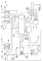
- a recovery unit 9 is connected to a return port 10 of the control valve unit 2 for recovering energy from the work function 1.
- the recovery unit 9 is connected between the return port 10 and the tank 4.
- the hydraulic system also comprises a means 11 for limiting the pressure of the hydraulic fluid at the return port 10.
- the pressure limiting means 11 includes a pilot-operated valve 12 adapted to set a maximum allowable pressure at the return port 10 of the control valve unit 2, which pressure is variable by controlling the pilot-operated valve 12 by means of a control unit 13.
- the control unit 13 is further connected to the control valve unit 2 in order to control the magnitude of the flow of hydraulic fluid to and from the work function 1 by means of the control valve unit. This control, in its turn, is depending on the speed desired for the piston 6.
- An actuator 14 can be adapted to actuate the work function 1 and to request the desired speed of the work function 1.
- the recovery unit 9 is a hydraulic motor or a hydraulic machine, which can function both as a hydraulic motor and a pump.
- a return flow from the work function 1 drives the hydraulic machine 9, which results in a work W done on a shaft 15 of the hydraulic machine 9.
- This energy can then be used or stored.
- a generator can be connected to the hydraulic machine for converting the mechanical work into electrical energy.
- the work function 1 is connected in such a way that a return flow from either the piston side or piston rod side of the hydraulic cylinder can be used for energy recovery.
- the pilot-operated valve 12 is connected to the return port 10 of the control valve unit 2 and connected in parallel with the recovery unit 9. Furthermore, the pilot-operated valve 12 is suitably electrically controllable by means of the control unit 13 and so designed that the maximum allowable pressure at the return port 10 of the control valve unit 2 is continuously variable. Accordingly, a desired maximum pressure can be set at the return port 10 of the control valve unit 2 during energy recovery. At a pressure which exceeds the maximum allowable pressure, the pilot-operated valve 12 will open for a flow through the valve, which flow can be directed to tank 4. At a lower pressure of the return flow, the pilot-operated valve 12 will be closed, and the return flow will drive the hydraulic machine 9 as long as the resistance from the hydraulic machine 9 does not create a pressure which exceeds the maximum allowable pressure.
- the pressure drop across the control valve unit 2 can be adjusted in a flexible manner, which is adapted to the actual operating situation, in that the pressure limiting means 11 comprises the pilot-operated valve 12. Thereby, the energy recovery thus can be adapted to the actual operating situation.
- a pressure level which is also adapted to the pressure prevailing in the hydraulic fluid upstream of the control valve unit 2, is obtained at the return port 10 of the control valve unit.
- the recovery unit is preferably connected to the control unit 13 to enable control of the recovery unit 9. For instance, the displacement of the hydraulic machine can be varied by means of the control unit 13.
- the pressure drop across the control valve unit 2 can be reduced for recovering energy via the recovery unit 9, at the same time as the required modulation of requested flow (and the desired speed of the piston 6) can be achieved. Assuming that all recovered energy can be used or stored, the pressure drop across the control valve unit 2 is suitably kept as small as possible in order to maximize the energy recovery, but sufficiently large to achieve the modulation of the requested return flow of hydraulic fluid.
- the hydraulic system can further comprise a check valve 16, which is connected in series with the recovery unit 9 in a position between the return port 10 of the control valve unit and the recovery unit 9.
- the check valve 16 is connected in series with the recovery unit 9 and connected in parallel with the pilot-operated valve 12 in order to block flow in a direction from the recovery unit 9 toward the work function 1 and to allow flow in a direction from the control valve unit 2 toward the recovery unit 9.
- a check valve is used for the respective pilot-operated valve, so that it is ensured that hydraulic fluid from the work function from which energy is to be recovered is not drained to tank via the pilot-operated valve of another work function.
- the hydraulic system can preferably comprise one or several pressure sensors 17, 19, 20, 22 for measuring the pressure of the hydraulic fluid upstream and downstream of the control valve unit on the supply and/or return side.
- These pressure sensors can also be integrated into the control valve unit.
- a pressure sensor 20 can be used for measuring the pressure on the piston rod side of the hydraulic cylinder wherein the recovery unit is used to boost the pressure in order to ensure that the biasing pressure is the desired one.
- a position sensor 21 can be used for indicating the position of a work implement. This will be described in greater detail below in an example where the recovery unit is used for obtaining a damped suspension of a work implement with the purpose of controlling the position of the work implement relative to the machine body of the working machine.
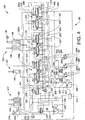
- FIG 3 shows a hydraulic system 201.
- the hydraulic system is designed to perform the hydraulic work functions of the wheel loader 101 (see also Figure 1 ).
- Figure 4 shows the hydraulic system of Figure 3 comprising a first example of an energy recovery system 301 shown in detail.
- the hydraulic system 201 is provided with a first work function 203 for lifting and lowering the lift arm unit of the wheel loader.
- the work function comprises said two hydraulic cylinders 108, 109 for operating the lift arm unit 106.
- the control valve unit 200b comprises two control valves 207, 209, in the form of flow valves, for the lifting and lowering movement. These control valves are arranged between the pump 205 and the lifting cylinders 108, 109 in the circuit, for controlling the lifting and lowering movement.
- the first 207 of these valves is adapted to connect the pump 205 to the piston side of the hydraulic cylinders 108, 109, and a second 209 one of these valves is adapted to connect the tank 243 to the piston rod side of the hydraulic cylinders.
- control valve unit 200c for the steering function comprises two control valves 210, 211, in the form of flow valves, arranged between the pump 205 and the steering cylinders 104, 105 in the circuit for steering the working machine.
- the steering cylinders can also be operated by means of an operator-controlled element 214 (shown in Figure 3 ), in the form of a steering lever, which is operatively connected to the control unit 213.
- the control unit 213 is adapted to receive control signals from the steering lever 214 and to control the control valves 210, 212 according to the lever position.
- a prioritizing valve 220 is arranged on the output conduit 245 of the pump for automatically prioritizing the steering function over the lift function and the tilt function, with the purpose of ensuring that the steering always gets the required pressure and flow.
- the prioritizing valve 220 regulates on pressure and ensures that the steering receives the required pressure. When at correct pressure, also the required flow to the steering is obtained, which occurs at the expense of the other work functions if the total hydraulic fluid requirement would exceed what the system is capable of providing.
- the lever control function of the system comprises two pressure sensors 216, 218, out of which one 216 is adapted to measure the pressure on the piston rod side of a steering cylinder (and is suitably arranged on a conduit to the piston rod side of the steering cylinder) and the second one 218 is adapted to measure the pressure on the piston side of the steering cylinder (and is suitably arranged on a conduit to the piston side of the steering cylinder).
- the hydraulic system can further comprise an electrically controlled valve 241 adapted to control the pressure on the pressure side of the pump via a hydraulic signal.
- the system 201 can also comprise an additional pressure sensor 239 for sensing a pressure which is indicative of the pressure on the pressure side of the pump.
- the pressure sensor 239 is preferably adapted to sense the pressure in a position downstream of the electrically controlled valve 241.
- the control unit registers the pressure in the hydraulic cylinder in question.
- the control unit then adjusts the valve 241 to obtain the desired pressure in the L S conduit (which in its turn controls the pressure of the pump).
- the pressure sensor 239 is adapted to sense the pressure and the control unit 213 is adapted to receive a signal from the pump pressure sensor 239 with information about the pressure level.
- the pressure sensor 239 will sense the pump pressure directly, when the valve 241 is fully open, but in normal operation modes the pressure sensor 239 senses the modulated pressure from the valve 241. This function implies that the hydraulic system can be operated with a variable control pressure.
- the control unit 213 is preferably adapted to coordinate the opening degree of the control valves 207, 209 and the output pressure of the pump 205 for optimum operation.
- FIG. 4 shows one said recovery unit 295 and a pressure limiting means 287b, 289b, 291b for the respective work function.
- Each pressure limiting means comprises one said pilot-operated valve 287, 289, 291.
- the recovery unit 295 suitably a hydraulic machine, is connected to a generator (or to an electric machine which can function both as a generator and a motor) in order to, together with the pilot-operated valves, produce a recovery system 301 for electrical energy.
- the respective pilot-operated valve 287, 289, 291 is connected to the return port 60a, 60b, 60c of the respective control valve unit.
- the energy recovery system 301 comprises a plurality of first conduits 280, 282, 284 on which the pilot-operated valves 287, 289, 291 are arranged.
- the respective said first conduit comprises a pilot-operated valve and is connected between a return conduit 281, 283, 285 from one of said work functions and the tank 243 in the hydraulic system.
- the energy recovery system 301 comprises a plurality of branch conduits 303, 305, 307 on which check valves 297, 298, 299 are arranged.
- the respective branch conduit 303, 305, 307 is arranged between the respective first conduit 280, 282, 284 and the second conduit 293 in order to block flow in a direction from the recovery unit 295 toward the respective work function by means of the check valves.
- the energy recovery system 301 further comprises a pressure sensor 309 in the second conduit 293 upstream of the recovery unit 295.
- the first conduits 280, 282, 284 are further connected to the second conduit 293 downstream of the pilot-operated valves 287, 289, 291 and the recovery unit 295.
- the respective pilot-operated valve 287, 289, 291 is connected in parallel with the recovery unit.
- the electronic control unit 213 (shown in Figure 3 ) is adapted to control each of the pilot-operated valves 287, 289, 291 (shown in Figure 4 ) individually to achieve energy recovery from one of the work functions.
- the control unit 213 is further adapted to receive a signal with information about the pressure, sensed by the pressure sensor 309, resulting from the resistance from the recovery unit 295 (within the range of the maximum allowable pressure set by the pilot-operated valve in question).
- the return flows of the work functions pass via the energy recovery system 301.
- more or fewer work functions can be connected to the energy recovery system.
- both piston side and piston rod side of the hydraulic cylinder are connectable to the energy recovery unit by means of the control valve unit, there is of course a possibility to choose to have only one cylinder side connectable for one or several work functions.
- the return flow from the other cylinder side then suitably has its outlet in tank.
- Hydraulic fluid can now flow from the piston side of the lifting cylinders 108, 109 through the control valve 207, via the check valve 298, and through the hydraulic motor 295 and further to the tank 243 via a counterpressure valve 311.
- Hydraulic fluid will only pass the pilot-operated valve 298 to the extent that temporary pressure peaks arise and/or flow peaks arise which the hydraulic motor cannot handle.
- the piston rod side of the lifting cylinders 108, 109 is filled via anticavitation valves in a conventional manner.
- the generator 313 which is driven by the hydraulic motor 295, can deliver the recovered energy in the form of electrical energy to, for example, an energy storing means 314, such as a battery or a capacitor.
- both control valves 207, 209 can be controlled so that their outlets to the energy recovery system are opened, which means that both the piston side and the piston rod side are connected to the recovery unit. This, in its turn, will result in a reduced return flow to the recovery system (but a higher pressure), since the lowering operation will be carried out primarily by hydraulic fluid flowing from the piston side to the piston rod side. This can be used, for example, when the bucket is empty and a rapid lowering is to take place without risking overspeeding the hydraulic motor 295.
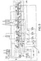
- FIG. 5 shows a further development of the embodiment in Figure 4 .
- a pressure limiter 321 such as a hydraulic pressure limiting valve, is arranged on a conduit 323 connecting the return conduit 285 from the lever control function and the tank 243.
- the reliability is increased further since it can be ensured that the steering function will be supplied also in case of an electrical malfunction causing a stop in the return flow. If a malfunction should occur in the recovery system, the return flow of hydraulic fluid can still always reach the tank 243 via the pressure limiting valve 321.
- the opening pressure of the pressure limiting valve is suitably set slightly above the pressure level desired for use in the energy recovery system.
- This pressure limiting valve 321 could also, alternatively, be used with regard to the steering wheel steering.
- energy is recovered when several work functions are used simultaneously. If, for example, lifting and steering are used simultaneously and the lift function requires the pump pressure 200 bar and the steering 50 bar, the energy recovery system can boost the return pressure to the steering with 150 bar. This means that the 200 bar pump pressure can be used both for lifting and for steering. The biased energy from the steering is recovered.
- the hydraulic system preferably comprises a sensor 50 for determining a reference position for the work implement which is mounted on the working machine.
- the work implement is movable relative to the machine body of the working machine by means of one said hydraulic work function.
- the work implement can, for example, be the lifting assembly or other types of functions where the undesired kinetic energy of the machine body and/or the work implement is recovered at the same time as the relative movement is damped.
- the recovery unit is adapted to dampen a relative movement, at least in one direction, between the work implement and the machine body.
- the control unit registers the position of the lifting assembly relative to the machine body.
- the computer of the control unit stores into memory the position the lifting assembly had immediately before the suspension function was actuated and the actual pressure level on the piston and/or piston rod side of the hydraulic cylinder.
- the lift arm assembly is usually pivotally connected to the machine body of the working machine. This means that if the working machine drives on a bumpy surface, i.e. drives over a small elevation (a bump) and/or into a small hole, this is reflected in the hydraulic cylinders in the form of changes in pressure on the piston and piston rod sides.
- the control valve 209 opens the piston rod sides to the tank 243.
- the control valve 207 to the pump 205 is opened so that oil can be replenished and lifts the lift arm assembly a bit.
- the control valve 209 closes and the control valve 207 opens to the recovery system so that the assembly is lowered, wherein the flow of hydraulic fluid generates electrical energy in the recovery system.
- the system creates conditions for a variable "springing/damping" characteristic.
- the system essentially works like a spring with damping, i.e. if a disturbance pushes the lifting assembly down, electrical power is obtained by driving the generator, and at the same time the movement is decelerated (like a spring) by means of the above control strategies.
- a certain power level will be added, which then abates so that the lifting assembly stops.
- the form of this spring characteristic can be a function of the following, or parts thereof:
- An electrically controlled valve 515 is arranged on a tank conduit 517 connecting the hydraulic machine 595 to the tank 243.
- the valve can be used to in order to be able to prevent flow of hydraulic fluid from the hydraulic machine to the tank 243.
- a pump conduit 521 is adapted to connect the hydraulic machine to the outlet side (pressure side) of the main pump 205.
- This pump conduit 521 is suitably connected at one of its ends to the tank conduit 517 in a position between the hydraulic machine 595 and the valve 517, and connected at its other end to the outlet side of the main pump 205.
- a check valve 519 can be arranged on the pump conduit 521. Thereby, hydraulic fluid is prevented from reaching the energy recovery system directly in a direction from the main pump 205.
- a check valve 523 can also be arranged on the outlet side of the main pump so that hydraulic fluid from the energy recovery system cannot pass to the tank 243 via the main pump 205.
- the recovery unit can also provide hydraulic fluid to the work functions of the hydraulic system.
- the recovery unit uses hydraulic fluid arriving from the return line of a work function.
- the check valve 523 at the main pump 205b has been eliminated.
- the main pump 205b is adapted to function both as a pump and a hydraulic motor.
- the pump is adapted to provide a torque when hydraulic fluid flows from the recovery unit 595b to the pressure side 50b of the pump and further through the pump to the suction side 51b of the pump, at the same time as the pump provides the required pressure on the pressure side for supplying the work functions.
- the hydraulic machine 595b can be connected to an electric machine 513 and can, in the same way as described previously, function as a hydraulic motor for recovering energy, or as a pump for increasing the pressure of the return flow.
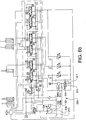
- the main pump 205b is connected to the driveline 52b of the working machine (schematically illustrated in Figure 6b ) for transferring a torque to the driveline when recovering energy.
- the driveline has a power take-off (PTO).
- PTO power take-off
- the power taken off at the PTO can then be used for an optional function of the working machine.
- the main pump 205b which in this case can operate both as a pump and a hydraulic motor, is adapted to maintain the required pressure on the pressure side at the same time as an excess flow of hydraulic fluid from the recovery unit 595b can flow via the conduit 521 and further through the main pump 205b and to the tank 243.
- the main pump which preferably is a variable load sensing pump of the type "over-centre variable displacement pump" is also mechanically connected to the driveline 52b, and can thus be used to generate a torque on the driveline in that hydraulic fluid flows "backwards" through the pump 205b to the tank 243.
- This can be particularly advantageous in operation modes where one or several work functions generate relatively large return flows, at the same time as the flow requirement on the supply side, at the moment in question, is relatively low. Also in case an energy storage connected to the electric machine 513 would be full, there is a possibility to recover energy via the main pump 205b instead.
- the pilot-operated valve 287 is controlled so that the required maximum allowable pressure is obtained, which means that the entire return flow of hydraulic fluid from the work function is directed to the hydraulic machine 595.
- Different strategies can be used depending on the pressure of the return flow relative to the pressure on the pressure side of the main pump:
- all energy can be stored in an electrical energy storage unit and be consumed later or be used for other electricity consumers.
- the recovered energy can be used for different needs. For example, at low diesel engine speeds, the electrical energy can be used to generate higher cylinder speeds in the work functions, or to release more engine power to the driveline.
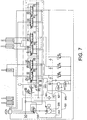
- the recovery unit is used to provide the hydraulic system 201 with a function in the form of a standby steering pump. See Figure 7 .
- a suction conduit 601 enabling the hydraulic machine 595 to draw hydraulic fluid from the tank 243, is added.
- the suction conduit 601 is preferably adapted to extend from the second conduit 293 to the tank 243 so that the hydraulic machine 595 can draw hydraulic fluid from the tank 243.
- a check valve 621 can be arranged on the suction conduit 601. By means of the suction conduit 601, the hydraulic machine 595 could deliver hydraulic fluid to the steering system in case the main pump 205, for some reason, would not be capable of providing hydraulic fluid.
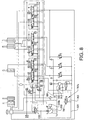
- the energy recovery system is used to recover energy during a deceleration of the working machine 101. See Figure 8 .
- the main pump 205 is drivable by means of the driveline 205b of a working machine and is adapted to brake the driveline during deceleration of the working machine.
- the hydraulic system comprises a hydraulic control means 701b for controlling a flow of hydraulic fluid from the pressure side of the pump 205 to the recovery unit 595 to recover energy during deceleration of the working machine.
- the embodiment of the hydraulic system in Figure 8 comprises said control means 701b in the form of an electrically controlled valve 701 and a conduit 703.
- the valve 701 is arranged on the conduit 703 connecting the suction conduit 601 and the pump conduit 521.
- flow is driven from the pump 205 via the valve 701 to the recovery unit, where the hydraulic energy can be converted into electrical energy for direct consumption or storage in a storage unit.
- the machine will be decelerated to an extent corresponding to the energy required to drive the pump (and the hydraulic machine and the generator).
- Adjustment of the deceleration level can, for example, take place by modulating the maximum L S signal to the pump and to thereafter control the electric machine 513 by torque or speed control.
- the pressure level multiplied by the flow passing the recovery unit corresponds to the deceleration effect which can be achieved.
- the flow can be determined either by direct speed control of the electric machine, or by controlling the load (torque) which will correspond to a certain speed (and thereby a certain flow). If other functions are supplied simultaneously by the main pump, the electric machine 513 is controlled so that pressure and flow is continuously maintained to these other functions and the remaining part passes to the recovery unit.
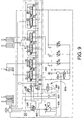
- the second hydraulic machine 903 will be referred to as a pump and the first hydraulic machine 295 as a hydraulic motor.
- This arrangement of pump and motor with an intermediate shaft for power transmission forms a hydraulic torque converter.
- a hydraulic energy storage 905, for example in the form of an accumulator, is connected to an outlet side of the pump 903.
- the outlet side of the pump 903 is further connected to the hydraulic system 201 via a conduit 907 which is connected to the suction side of the main pump 205. Accordingly, energy stored in the accumulator 905 can be delivered back to the system via the suction side of the main pump 205.
- the main pump will function as a hydraulic motor supporting the diesel engine.
- energy is recovered when lowering the lift arm assembly 111.
- the control unit registers that the operator wants to lower the lift arm assembly via the lift lever.
- the control unit sets the pilot-operated valve 289, associated with the lifting cylinders 108, 109, to a maximum allowable pressure, which means that the required pressure for the recovery unit can be achieved, and opens the control valve 207.
- Hydraulic fluid can now flow from the piston side of the lifting cylinders 108, 109 through the control valve 207, through the check valve 298, and further through the hydraulic motor 295 and then further to the tank 243 via the counterpressure valve 311.
- the piston rod side of the lifting cylinders 108, 109 is replenished in a conventional manner by means of the anticavitation valves arranged in the control valve unit.
- the pressure of the return flow passing through the motor 295 depends on the pressure in the hydraulic cylinder (which in its turn depends on the actual load).
- the pressure on the pressure side of the pump 903 is dependent on how much the gas in the accumulator 905 is compressed. This means that the pressure in the accumulator 905 and the pressure of the hydraulic fluid before the hydraulic motor 295 are essentially never equal.
- all recovered energy can be taken care of in the accumulator 905, irrespective of pressure levels.
- both the control valve 207 and control valve 209 can open the outlet to the recovery unit, which means that both the piston side and the piston rod side are connected to the recovery unit.
- energy is recovered when steering with the steering wheel (via orbitrol unit).
- Energy recovery during steering wheel steering by means of a system according to the embodiment in Figure 10 takes place in substantially the same manner as for energy recovery during steering wheel steering by means of the system according to the embodiment in Figure 4 , with some differences:
- energy is recovered when several work functions are used simultaneously. This works in substantially the same way as described above for the hydraulic system shown in Figure 4 .
- the hydraulic system is used as an active suspension system for a work function, such as for example the lift function, where the undesired kinetic energy of the machine body and/or the work implement is at least partially recovered.
- a work function such as for example the lift function
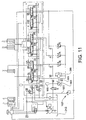
- the main pump 205 is driven by the driveline at the same time as the main pump 205 brakes the driveline. Thereby, the main pump pumps a flow of hydraulic fluid via the valve 1101 to the recovery unit.
- the working machine is decelerated to an extent corresponding to the energy required to drive the main pump 205 (and the recovery unit).
- the valve 1101 is preferably kept fully open. Adjustment of the deceleration level can take place by calculating and adjusting the L S signal to the main pump (since the L S signal constitutes a reference signal for the pressure regulator of the pump), and adjustment of the displacement of the pump 903.
- the flow can be calculated with input data from the speed sensor 909.
- the deceleration effect is proportional to the pressure multiplied by the flow.
- the L S signal to the main pump is determined by the highest pressure of the pressure required for the other work functions and the pressure required to obtain the desired deceleration effect (deceleration energy). Calculation of how much energy can be recovered is performed and the displacement of the pump 903 is adjusted accordingly.
- the flow across the hydraulic motor 295 is calculated (by means of the speed sensor 909) and the flow going out to other work functions is calculated (by means of slide position and pressure drop of associated control valves). If steering wheel steering with orbitrol unit is used, for example, a steering position sensor can be used to calculate the flow to the steering. If the recovery unit cannot receive a pressure and/or flow corresponding to the required amount of deceleration energy, a certain amount of energy can be dumped by controlling the control valve 1101 so that a corresponding pressure drop arises across it.
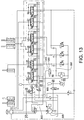
- Figure 13 shows an alternative embodiment to the embodiment in Figure 12 .
- the electrically control valve 1201 is arranged on a conduit 1203 connecting the second conduit 293 in the recovery system to a supply conduit 805 arranged between the main pump 205 and the work functions.
- the conduit 1203 is connected to the supply conduit 805 in a position between the prioritizing valve 220 and the work functions.
- the prioritizing valve 220 will prioritize a flow from the main pump 205 to the steering at the expense of the supply to the work functions and/or the recovery unit.
- the hydraulic system is used to supply recovered energy from an accumulator to the main pump.
- the pressure in the accumulator is dependent on how much the gas is compressed, and the pressure required by the hydraulic cylinder depends on the actual load situation. Either the pressure in the accumulator is lower than the pressure requirement of the hydraulic cylinder, which will mean that the hydraulic cylinder does not move at all, or the pressure in the accumulator is higher than the pressure requirement of the hydraulic cylinder, which means that energy has to be throttled away via a valve to enable the speed of the hydraulic cylinder piston to be controlled.
- the accumulator 905 is connected to the suction side of the pump 205 via the valve 913.
- a check valve 915 on a conduit between the main pump 205 and the tank 243 prevents the pressurized oil from the accumulator 905 from passing to the tank 243.
- the valve 913 When the valve 913 is closed, the main pump draws oil in a conventional manner from the tank. The power required to drive the pump is proportional to the pressure difference between pressure and suction side of the pump multiplied by the flow through the pump.
- the valve 913 is opened, the pressure in the accumulator is supplied to the suction side of the pump, which reduces the pressure difference between pressure and suction side of the pump 205.
- the term “electrically controlled valve” has been used for a direct electrically controlled valve in a hydraulic conduit, that is to say the valve is adapted to be controlled via an input electrical signal.
- electrically controlled valve such as an arrangement of several valves, out of which a first valve is arranged on the hydraulic conduit and a second direct electrically controlled valve is adapted to control the first valve via a hydraulic signal.
Landscapes
- Engineering & Computer Science (AREA)
- General Engineering & Computer Science (AREA)
- Mining & Mineral Resources (AREA)
- Civil Engineering (AREA)
- Structural Engineering (AREA)
- Physics & Mathematics (AREA)
- Fluid Mechanics (AREA)
- Mechanical Engineering (AREA)
- Chemical & Material Sciences (AREA)
- Analytical Chemistry (AREA)
- Operation Control Of Excavators (AREA)
- Fluid-Pressure Circuits (AREA)
Claims (30)
- Système hydraulique pour une machine de travail (101), comprenant au moins une fonction de travail (1 ; 217, 221, 203) et une unité de soupape de commande (2 ; 200a, 200b, 200c) pour commander un fluide hydraulique en direction de et en provenance de la fonction de travail, et une unité de récupération (9 ; 295 ; 595) reliée à un orifice de retour (10 ; 60a, 60b, 60c) de l'unité de soupape de commande pour récupérer de l'énergie de la fonction de travail, et un moyen (11 ; 287b, 289b, 291b) pour limiter la pression du fluide hydraulique au niveau de l'orifice de retour, où le moyen de limitation de pression comprend une soupape à commande pilotée (12 ; 287, 289, 291) agencée pour définir une pression maximale admissible au niveau de l'orifice de retour (10 ; 60a, 60b, 60c) de l'unité de soupape de commande, laquelle pression est variable en commandant la soupape à commande pilotée au moyen d'une unité de commande (13 ; 213), caractérisé en ce que la pression maximale admissible au niveau de l'orifice de retour (10 ; 60a, 60b, 60c) de l'unité de soupape de commande (2 ; 200a, 200b, 200c) est variable en continu au moyen de la soupape à commande pilotée (12 ; 287, 289, 291).
- Système hydraulique selon la revendication 1, caractérisé en ce que la soupape à commande pilotée (12 ; 287, 289, 291) est reliée à l'orifice de retour (10 ; 60a, 60b, 60c) et est reliée en parallèle à l'unité de récupération (9 ; 295 ; 595).
- Système hydraulique selon la revendication 1 ou 2, caractérisé en ce que la soupape à commande pilotée (12 ; 287, 289, 291) est commandée électriquement.
- Système hydraulique selon l'une quelconque des revendications précédentes, caractérisé en ce que le système comprend un clapet anti-retour (16 ; 297, 298, 299) qui est relié en série à l'unité de récupération (9 ; 295 ; 595) dans une position située entre l'orifice de retour (10 ; 60a, 60b, 60c) de l'unité de soupape de commande et l'unité de récupération, et que le clapet anti-retour est relié en parallèle à la soupape à commande pilotée (12 ; 287, 289, 291) afin de bloquer l'écoulement dans une direction allant vers la fonction de travail (1 ; 217, 221, 203).
- Système hydraulique selon l'une quelconque des revendications précédentes, caractérisé en ce que le système comprend un capteur de pression (17 ; 309) adapté pour mesurer la pression du fluide hydraulique dans une position située entre l'orifice de retour (10 ; 60a, 60b, 60c) de l'unité de soupape de commande et l'orifice d'entrée (18 ; 280b, 282b, 284b) de la soupape à commande pilotée.
- Système hydraulique selon l'une quelconque des revendications précédentes, caractérisé en ce que le système comprend une pompe (3 ; 205) pour fournir un fluide hydraulique.
- Système hydraulique selon la revendication 6, caractérisé en ce que la pompe (3 ; 205) est adaptée pour fournir un fluide hydraulique audit au moins une fonction de travail (1 ; 217, 221, 203).
- Système hydraulique selon la revendication 7, caractérisé en ce que le système comprend un moyen (520) pour renvoyer l'énergie, récupérée d'un flux de retour de la fonction de travail, au côté refoulement de la pompe.
- Système hydraulique selon les revendications 7 et 8, caractérisé en ce que la pompe (205b) est adaptée pour fonctionner à la fois comme une pompe et un moteur hydraulique, et que la pompe est adaptée pour fournir un couple lorsque le fluide hydraulique s'écoule de l'unité de récupération (595b) au côté refoulement (50b) de la pompe et en outre à travers la pompe au côté aspiration (51b) de la pompe, au même temps où la pompe fournit une pression requise sur le côté refoulement pour alimenter la fonction de travail (1 ; 217, 221, 203).
- Système hydraulique selon la revendication 7 ou 8, caractérisé en ce que le système comprend un moyen (900) pour renvoyer l'énergie, récupérée d'un flux de retour de la fonction de travail, au côté aspiration de la pompe (205).
- Système hydraulique selon l'une quelconque des revendications précédentes, caractérisé en ce que l'unité de récupération comprend une première machine hydraulique (295) et une deuxième machine hydraulique (903), et que les première et deuxième machines hydrauliques sont reliées mécaniquement entre elles, et que la première machine hydraulique est adaptée pour être entraînée par un écoulement de fluide hydraulique et la deuxième machine hydraulique est adaptée pour pomper le fluide hydraulique en étant entraînée par la première machine hydraulique.
- Système hydraulique selon la revendication 11, caractérisé en ce que la première machine hydraulique (295) est reliée à l'orifice de retour pour être entraînée par un écoulement de retour, et la deuxième machine hydraulique (903) est adaptée pour pomper le fluide hydraulique vers un accumulateur (905).
- Système hydraulique selon les revendications 7 et 11, caractérisé en ce que la première machine hydraulique (295) est reliée à l'orifice de retour pour être entraînée par un écoulement de retour, et que la deuxième machine hydraulique (903) est adaptée pour pomper le fluide hydraulique vers le côté refoulement de la pompe.
- Système hydraulique selon les revendications 7 et 11, caractérisé en ce que la première machine hydraulique (295) est reliée à l'orifice de retour pour être entraînée par un écoulement de retour, et que la deuxième machine hydraulique (903) est adaptée pour pomper le fluide hydraulique vers le côté aspiration de la pompe.
- Système hydraulique selon l'une quelconque des revendications 6 à 10, caractérisé en ce que la pompe (205) est pilotable par la transmission d'une machine de travail et est adaptée pour freiner la transmission lors de la décélération de la machine de travail (101), et que le système comprend un moyen de commande hydraulique (701b ; 801b) pour commander un écoulement de fluide hydraulique, du côté refoulement de la pompe à l'unité de récupération, pour récupérer de l'énergie lors de la décélération de la machine de travail.
- Système hydraulique selon l'une quelconque des revendications précédentes, caractérisé en ce que ladite au moins une fonction de travail (1 ; 217, 221, 203) comprend un vérin hydraulique muni d'un piston pour transférer de la puissance à un composant de machine dans une machine de travail.
- Système hydraulique selon la revendication 16, caractérisé en ce que l'unité de soupape de commande (2 ; 200a, 200b, 200c) est adaptée pour commander un écoulement de retour de fluide hydraulique, optionnellement du côté piston du vérin hydraulique et/ou du côté tige de piston du vérin hydraulique, à l'unité de récupération.
- Système hydraulique selon l'une quelconque des revendications 16 et 17, caractérisé en ce que le système comprend un capteur de pression (19 ; 235, 229, 216) adapté pour mesurer la pression du fluide hydraulique sur le côté piston du vérin hydraulique.
- Système hydraulique selon l'une quelconque des revendications 16 à 18, caractérisé en ce que le système comprend un capteur de pression (20 ; 237, 231, 218) adapté pour mesurer la pression du fluide hydraulique sur le côté tige de piston du vérin hydraulique.
- Système hydraulique selon l'une quelconque des revendications précédentes, caractérisé en ce que l'unité de récupération (9 ; 295 ; 595) est adaptée pour amortir un mouvement relatif causé par une perturbation externe, au moins dans une direction, entre un outil de travail (111) et un corps de machine (102) de la machine de travail (101), lequel outil de travail est mobile par rapport au corps de machine au moyen de ladite fonction de travail (1 ; 217, 221, 203).
- Système hydraulique selon la revendication 20, caractérisé en ce que le système comprend un capteur (21 ; 50) pour déterminer une position de référence pour l'outil de travail (111) par rapport au corps de machine (102).
- Système hydraulique selon l'une quelconque des revendications précédentes, caractérisé en ce que le système comprend une pluralité de fonctions de travail (1 ; 217, 221, 203) avec une unité de soupape de commande respective associée (2 ; 200a, 200b, 200c), et qu'une telle soupape à commande pilotée (12 ; 287, 289, 291) est prévue pour la fonction de travail respective.
- Système hydraulique selon les revendications 4 et 22, caractérisé en ce que le système comprend un tel clapet anti-retour (16 ; 297, 298, 299) agencé pour une soupape à commande pilotée (287, 289, 291) respective, lequel clapet anti-retour est relié en série à l'unité de récupération (295) dans une position située entre l'orifice de retour de l'unité de soupape de commande respective et l'unité de récupération, et est relié en parallèle à la soupape à commande pilotée, afin de bloquer l'écoulement dans une direction allant vers la fonction de travail respective (217, 221, 203).
- Système hydraulique selon la revendication 23, caractérisé en ce que les sorties desdits clapets anti-retour (297, 298, 299) sont reliées entre elles en amont de l'unité de récupération.
- Système hydraulique selon la revendication 24, caractérisé en ce que le système comprend un capteur de pression (309) adapté pour mesurer la pression du fluide hydraulique dans une position située en aval des clapets anti-retour et en amont de l'unité de récupération.
- Système hydraulique selon l'une quelconque des revendications 22 à 24, caractérisé en ce que le système comprend un capteur de pression pour la soupape à commande pilotée respective adapté pour mesurer la pression du fluide hydraulique dans une position située entre l'orifice de retour de l'unité de soupape de commande respective et l'orifice d'entrée de la soupape à commande pilotée respective.
- Système hydraulique selon la revendication 22 ou 23, caractérisé en ce que le système comprend une telle unité de récupération pour la fonction de travail respective.
- Système hydraulique selon l'une quelconque des revendications 22 à 27, caractérisé en ce que le système comprend une unité de commande (13 ; 213) pour une commande individuelle des soupapes à commande pilotée (12 ; 287, 289, 291).
- Machine de travail (101) comprenant un système hydraulique selon l'une quelconque des revendications 1 à 28.
- Procédé de récupération d'énergie dans un système hydraulique, dans lequel le système hydraulique comprend au moins une fonction de travail (1 ; 217, 221, 203) et une unité de soupape de commande (2 ; 200a, 200b, 200c) pour commander un fluide hydraulique en direction de et en provenance de la fonction de travail, et une unité de récupération (9 ; 295 ; 595) reliée à un orifice de retour (10 ; 60a, 60b, 60c) de l'unité de soupape de commande pour récupérer de l'énergie de la fonction de travail, caractérisé en ce que la pression maximale admissible au niveau de l'orifice de retour (Pmax) est commandée en continu par un moyen de limitation de pression (11 ; 287b, 289b, 291b) en recevant des signaux à partir d'une unité de commande (13 ; 213) dans le but d'adapter le taux de récupération d'énergie maximal de l'unité de récupération (9 ; 295 ; 595) à un mode de fonctionnement réel de ladite fonction de travail (1 ; 217, 221, 203).
Applications Claiming Priority (1)
| Application Number | Priority Date | Filing Date | Title |
|---|---|---|---|
| PCT/SE2009/000282 WO2010138029A1 (fr) | 2009-05-29 | 2009-05-29 | Système hydraulique et machine de travail comprenant un tel système hydraulique |
Publications (3)
| Publication Number | Publication Date |
|---|---|
| EP2435717A1 EP2435717A1 (fr) | 2012-04-04 |
| EP2435717A4 EP2435717A4 (fr) | 2017-01-18 |
| EP2435717B1 true EP2435717B1 (fr) | 2019-05-08 |
Family
ID=43222917
Family Applications (1)
| Application Number | Title | Priority Date | Filing Date |
|---|---|---|---|
| EP09845306.1A Active EP2435717B1 (fr) | 2009-05-29 | 2009-05-29 | Système hydraulique et machine de travail comprenant un tel système hydraulique |
Country Status (6)
| Country | Link |
|---|---|
| US (1) | US9074347B2 (fr) |
| EP (1) | EP2435717B1 (fr) |
| JP (1) | JP5567663B2 (fr) |
| KR (1) | KR20120040684A (fr) |
| CN (1) | CN102449323B (fr) |
| WO (1) | WO2010138029A1 (fr) |
Families Citing this family (56)
| Publication number | Priority date | Publication date | Assignee | Title |
|---|---|---|---|---|
| US8807263B2 (en) * | 2010-04-12 | 2014-08-19 | Volvo Compact Equipment Sas | Excavator and process for assembling or dissassembling such excavator |
| KR20140022021A (ko) * | 2011-03-17 | 2014-02-21 | 파커-한니핀 코포레이션 | 여러 기능부를 제어하는 전기 유압 시스템 |
| JP5817311B2 (ja) * | 2011-08-08 | 2015-11-18 | ダイキン工業株式会社 | ハイブリッド型油圧装置 |
| WO2013035815A1 (fr) * | 2011-09-09 | 2013-03-14 | 住友重機械工業株式会社 | Pelle, et procédé de commande de celle-ci |
| US9387440B2 (en) | 2011-09-30 | 2016-07-12 | General Electric Company | Desalination system with energy recovery and related pumps, valves and controller |
| US9644761B2 (en) | 2011-09-30 | 2017-05-09 | General Electric Company | Desalination system with energy recovery and related pumps, valves and controller |
| US20130126023A1 (en) * | 2011-11-22 | 2013-05-23 | Tam C. Huynh | Hydraulic system with energy regeneration |
| US20130205762A1 (en) * | 2011-11-29 | 2013-08-15 | Vanguard Equipment, Inc. | Auxiliary flow valve system and method for managing load flow requirements for auxiliary functions on a tractor hydraulic system |
| WO2013095208A1 (fr) | 2011-12-22 | 2013-06-27 | Volvo Construction Equipment Ab | Procédé pour commander l'abaissement d'un accessoire d'une machine de travail |
| US20130229272A1 (en) * | 2012-03-05 | 2013-09-05 | Caterpillar Inc. | Manual control device and method |
| US20150308079A1 (en) * | 2012-05-30 | 2015-10-29 | Volvo Construction Equipment Ab | A method for recovering energy and a hydraulic system |
| US9279236B2 (en) | 2012-06-04 | 2016-03-08 | Caterpillar Inc. | Electro-hydraulic system for recovering and reusing potential energy |
| US8807255B2 (en) * | 2012-09-24 | 2014-08-19 | Caterpillar Paving Products Inc. | Engine hot air deflector |
| US9290912B2 (en) | 2012-10-31 | 2016-03-22 | Caterpillar Inc. | Energy recovery system having integrated boom/swing circuits |
| US9638179B2 (en) | 2012-12-04 | 2017-05-02 | General Electric Company | Hydraulic control system for a reverse osmosis hydraulic pump |
| US9897080B2 (en) | 2012-12-04 | 2018-02-20 | General Electric Company | Rotary control valve for reverse osmosis feed water pump with energy recovery |
| US9476415B2 (en) | 2012-12-04 | 2016-10-25 | General Electric Company | System and method for controlling motion profile of pistons |
| US9580888B2 (en) * | 2013-02-08 | 2017-02-28 | Doosan Infracore Co., Ltd. | Apparatus and method for controlling oil hydraulic pump for excavator |
| US9290911B2 (en) | 2013-02-19 | 2016-03-22 | Caterpillar Inc. | Energy recovery system for hydraulic machine |
| EP3004471B1 (fr) * | 2013-06-03 | 2018-02-14 | Volvo Construction Equipment AB | Système hydraulique pour machine de chantier et procédé de commande d'un système hydraulique |
| CA2838639C (fr) * | 2013-10-23 | 2016-07-19 | Ms Gregson | Procede et systeme pour commander l'inclinaison d'une fleche transportee par un vehicule |
| US20160290367A1 (en) * | 2013-12-19 | 2016-10-06 | Volvo Construction Equipment Ab | Hydraulic load sensing system |
| JP2015137753A (ja) * | 2014-01-24 | 2015-07-30 | カヤバ工業株式会社 | ハイブリッド建設機械の制御システム |
| EP2955389B1 (fr) * | 2014-06-13 | 2019-05-22 | Parker Hannifin Manufacturing Finland OY | Système hydraulique avec récupération d'énergie |
| DE102014218886B3 (de) * | 2014-09-19 | 2015-11-12 | Voith Patent Gmbh | Hydraulischer Antrieb mit Eilhub und Lasthub |
| FR3026811B1 (fr) * | 2014-10-03 | 2016-12-09 | Poclain Hydraulics Ind | Procede d'assistance hydraulique de l'entrainement d'un vehicule a basse vitesse |
| US9615499B2 (en) * | 2014-12-03 | 2017-04-11 | Cnh Industrial Canada, Ltd. | Hydraulic work unit leveling and calibration system for an agricultural implement |
| US9402344B1 (en) * | 2015-01-20 | 2016-08-02 | Deere & Company | Power management for sugarcane harvesters |
| WO2016190468A1 (fr) * | 2015-05-28 | 2016-12-01 | 볼보 컨스트럭션 이큅먼트 에이비 | Procédé de commande d'engin de chantier d'équipement de construction |
| DE102015015858A1 (de) * | 2015-12-03 | 2017-06-08 | Sauter Feinmechanik Gmbh | Überwachungseinrichtung für Werkzeugrevolver |
| DE102016002443A1 (de) * | 2016-02-29 | 2017-08-31 | Bomag Gmbh | Lenkeinrichtung, Baumaschine mit einer Lenkeinrichtung und Verfahren zum Lenken einer lenkbaren Maschine |
| SE1600171A1 (en) | 2016-05-19 | 2017-11-20 | Flutron Ab | Electrohydraulic drive and control system |
| DE102017100190B4 (de) | 2017-01-06 | 2018-11-15 | Danfoss Power Solutions Aps | Hydraulische Lenkanordnung |
| US10029533B1 (en) * | 2017-01-23 | 2018-07-24 | Caterpillar Underground Mining Pty Ltd | Vehicle suspension control system |
| DK179314B1 (en) * | 2017-02-08 | 2018-04-30 | Steeper Energy Aps | Pressurization system for high pressure treatment system |
| US11105347B2 (en) * | 2017-07-20 | 2021-08-31 | Eaton Intelligent Power Limited | Load-dependent hydraulic fluid flow control system |
| US10392774B2 (en) | 2017-10-30 | 2019-08-27 | Deere & Company | Position control system and method for an implement of a work vehicle |
| US10663252B1 (en) | 2017-12-15 | 2020-05-26 | John M. Sprainis | Shoulder-fired firearm primary and secondary recoil attenuator |
| CN108343651B (zh) * | 2017-12-21 | 2021-03-16 | 中国神华能源股份有限公司 | 养路机械作业装置应急救援方法 |
| CN108298474B (zh) * | 2017-12-26 | 2024-09-03 | 浙江大学 | 一种具有调速功能的叉车高效节能系统 |
| LT3761773T (lt) * | 2018-03-08 | 2023-09-11 | Precision Planting Llc | Žemės ūkio sodinamosios sėjos sekcija su skysčio reguliavimo sistema |
| CN112292535B (zh) * | 2018-07-06 | 2023-07-04 | 山特维克矿山工程机械有限公司 | 液压主从驱动马达控制系统 |
| EP3908757A1 (fr) | 2019-01-08 | 2021-11-17 | Parker Hannifin Corporation | Soupape de commande hydraulique ayant des orifices de travail en double et des fonctions de commande d'oscillation d'actionneur intégrées |
| WO2020196871A1 (fr) * | 2019-03-28 | 2020-10-01 | 住友重機械工業株式会社 | Excavatrice |
| US11708106B2 (en) * | 2019-07-02 | 2023-07-25 | Cnh Industrial America Llc | Steering systems and methods using active braking |
| CN110332163B (zh) * | 2019-07-25 | 2024-04-19 | 中国铁建重工集团股份有限公司 | 液压控制系统与铲运机 |
| WO2021115598A1 (fr) * | 2019-12-12 | 2021-06-17 | Volvo Construction Equipment Ab | Système hydraulique et procédé pour commander un système hydraulique d'une machine de travail |
| US11716921B2 (en) | 2020-09-03 | 2023-08-08 | Deere & Company | Method of a variable steering response for different steering operations of a working machine and system thereof |
| EP4101995A4 (fr) * | 2020-10-19 | 2024-03-13 | Hitachi Construction Machinery Co., Ltd. | Engin de chantier |
| KR20220091867A (ko) * | 2020-12-24 | 2022-07-01 | 현대두산인프라코어(주) | 건설기계 |
| CN113175452B (zh) * | 2021-05-17 | 2025-07-01 | 中国电建集团长春发电设备有限公司 | 一种轮式中速磨煤机液压定、变加载在线切换系统 |
| SE546159C2 (en) | 2022-01-10 | 2024-06-11 | Parker Hannifin Emea Sarl | A valve arrangement and a hydraulic actuator contol circuit |
| CN114810688B (zh) * | 2022-05-31 | 2025-09-09 | 山东临工工程机械有限公司 | 一种优先阀、液压系统及装载机 |
| CN114934918B (zh) * | 2022-06-29 | 2025-11-04 | 徐工集团工程机械股份有限公司科技分公司 | 一种滑移装载机液压系统及控制方法 |
| US12435490B2 (en) | 2022-06-30 | 2025-10-07 | Caterpillar Sarl | Electro-hydraulic controlled excavator travel to tool control priority function |
| CN118492323B (zh) * | 2024-07-17 | 2024-11-12 | 宁波力劲智能装备有限公司 | 一种具有能量回收功能的锁模系统 |
Family Cites Families (19)
| Publication number | Priority date | Publication date | Assignee | Title |
|---|---|---|---|---|
| KR100202203B1 (ko) * | 1993-11-30 | 1999-06-15 | 안자키 사토루 | 유압식 파워셔블의 직선 굴삭 제어 장치 |
| US5933346A (en) * | 1996-06-05 | 1999-08-03 | Topcon Laser Systems, Inc. | Bucket depth and angle controller for excavator |
| US6378301B2 (en) * | 1996-09-25 | 2002-04-30 | Komatsu Ltd. | Pressurized fluid recovery/reutilization system |
| US6735888B2 (en) * | 2001-05-18 | 2004-05-18 | Witten Technologies Inc. | Virtual camera on the bucket of an excavator displaying 3D images of buried pipes |
| JP2004011168A (ja) * | 2002-06-04 | 2004-01-15 | Komatsu Ltd | 建設機械 |
| JP3877307B2 (ja) | 2002-10-18 | 2007-02-07 | 株式会社小松製作所 | 圧油エネルギー回収装置 |
| JP2004324742A (ja) | 2003-04-23 | 2004-11-18 | Saxa Inc | 液圧装置 |
| WO2006132031A1 (fr) * | 2005-06-06 | 2006-12-14 | Shin Caterpillar Mitsubishi Ltd. | Dispositif d’entraînement pour rotation, et machine de travail |
| JP2007040393A (ja) * | 2005-08-03 | 2007-02-15 | Shin Caterpillar Mitsubishi Ltd | 流体圧回路 |
| JP2007056998A (ja) | 2005-08-24 | 2007-03-08 | Shin Caterpillar Mitsubishi Ltd | 旋回駆動装置および作業機械 |
| ITTO20050629A1 (it) * | 2005-09-15 | 2007-03-16 | Cnh Italia Spa | Disposizione idraulica per un braccio di sollevamento incernierato ad un veicolo |
| JP2007239894A (ja) * | 2006-03-09 | 2007-09-20 | Kayaba Ind Co Ltd | エネルギー変換装置 |
| JP4762022B2 (ja) | 2006-03-27 | 2011-08-31 | カヤバ工業株式会社 | エネルギー変換装置 |
| JP4704259B2 (ja) * | 2006-03-27 | 2011-06-15 | カヤバ工業株式会社 | エネルギー変換装置 |
| JP4773883B2 (ja) * | 2006-05-26 | 2011-09-14 | 住友建機株式会社 | 作業機械の制御装置 |
| EP1914353A3 (fr) * | 2006-10-19 | 2011-04-20 | Hitachi Construction Machinery Co., Ltd. | Engin de construction |
| JP4844363B2 (ja) * | 2006-11-28 | 2011-12-28 | コベルコ建機株式会社 | 油圧駆動装置及びこれを備えた作業機械 |
| JP2008275101A (ja) * | 2007-05-01 | 2008-11-13 | Daikin Ind Ltd | ハイブリッド式建設車両 |
| US7634911B2 (en) * | 2007-06-29 | 2009-12-22 | Caterpillar Inc. | Energy recovery system |
-
2009
- 2009-05-29 JP JP2012512999A patent/JP5567663B2/ja not_active Expired - Fee Related
- 2009-05-29 CN CN200980159587.8A patent/CN102449323B/zh active Active
- 2009-05-29 KR KR1020117028084A patent/KR20120040684A/ko not_active Ceased
- 2009-05-29 EP EP09845306.1A patent/EP2435717B1/fr active Active
- 2009-05-29 US US13/322,941 patent/US9074347B2/en active Active
- 2009-05-29 WO PCT/SE2009/000282 patent/WO2010138029A1/fr not_active Ceased
Non-Patent Citations (1)
| Title |
|---|
| None * |
Also Published As
| Publication number | Publication date |
|---|---|
| EP2435717A1 (fr) | 2012-04-04 |
| JP2012528288A (ja) | 2012-11-12 |
| JP5567663B2 (ja) | 2014-08-06 |
| WO2010138029A1 (fr) | 2010-12-02 |
| CN102449323A (zh) | 2012-05-09 |
| US20120067432A1 (en) | 2012-03-22 |
| EP2435717A4 (fr) | 2017-01-18 |
| CN102449323B (zh) | 2016-04-13 |
| KR20120040684A (ko) | 2012-04-27 |
| US9074347B2 (en) | 2015-07-07 |
Similar Documents
| Publication | Publication Date | Title |
|---|---|---|
| EP2435717B1 (fr) | Système hydraulique et machine de travail comprenant un tel système hydraulique | |
| US9932721B2 (en) | System, working machine comprising the system, and method of springing an implement of a working machine during transport | |
| KR101956959B1 (ko) | 단일 입력을 사용해서 리프트 스피드의 전체 범위를 획득하기 위한 방법 | |
| US7712309B2 (en) | Arrangement and a method for controlling a work vehicle | |
| CN101370987B (zh) | 用于工程机械的控制系统以及用于控制液压缸的方法 | |
| EP2215310B1 (fr) | Système de détection de charge, machine d'usinage comprenant le système et procédé pour commander une fonction hydraulique | |
| US11286642B2 (en) | Energy recovery system for off-highway vehicles with hydraulic transformer coupled to transmission power take-off | |
| CN109764027B (zh) | 具有能量回收功能的电液压作业车辆 | |
| US20030213238A1 (en) | Hydraulic regeneration system | |
| US9334629B2 (en) | Open-center hydraulic system with machine information-based flow control | |
| US7845458B2 (en) | Control system for frame-steering of a vehicle and method for controlling two steering cylinders in a frame-steered vehicle | |
| US20140060018A1 (en) | Hydraulic control system | |
| US20150308079A1 (en) | A method for recovering energy and a hydraulic system | |
| US6047545A (en) | Hydrostatic drive system | |
| US20220397133A1 (en) | Hydraulic system for hydro-mechanical machines comprising rotary mechanism and boom cylinder | |
| US6076350A (en) | Hydrostatic drive system for a vehicle | |
| US20040249537A1 (en) | Machine tool and method for operating machine tool |
Legal Events
| Date | Code | Title | Description |
|---|---|---|---|
| PUAI | Public reference made under article 153(3) epc to a published international application that has entered the european phase |
Free format text: ORIGINAL CODE: 0009012 |
|
| 17P | Request for examination filed |
Effective date: 20111229 |
|
| AK | Designated contracting states |
Kind code of ref document: A1 Designated state(s): AT BE BG CH CY CZ DE DK EE ES FI FR GB GR HR HU IE IS IT LI LT LU LV MC MK MT NL NO PL PT RO SE SI SK TR |
|
| RIN1 | Information on inventor provided before grant (corrected) |
Inventor name: EKVALL, ANDREAS Inventor name: VIGHOLM, BO Inventor name: HEYBROEK, KIM |
|
| DAX | Request for extension of the european patent (deleted) | ||
| REG | Reference to a national code |
Ref country code: DE Ref legal event code: R079 Ref document number: 602009058305 Country of ref document: DE Free format text: PREVIOUS MAIN CLASS: F15B0021140000 Ipc: E02F0009220000 |
|
| RIC1 | Information provided on ipc code assigned before grant |
Ipc: F15B 21/14 20060101ALI20161208BHEP Ipc: E02F 9/22 20060101AFI20161208BHEP |
|
| RA4 | Supplementary search report drawn up and despatched (corrected) |
Effective date: 20161215 |
|
| GRAP | Despatch of communication of intention to grant a patent |
Free format text: ORIGINAL CODE: EPIDOSNIGR1 |
|
| STAA | Information on the status of an ep patent application or granted ep patent |
Free format text: STATUS: GRANT OF PATENT IS INTENDED |
|
| INTG | Intention to grant announced |
Effective date: 20190103 |
|
| GRAS | Grant fee paid |
Free format text: ORIGINAL CODE: EPIDOSNIGR3 |
|
| GRAA | (expected) grant |
Free format text: ORIGINAL CODE: 0009210 |
|
| STAA | Information on the status of an ep patent application or granted ep patent |
Free format text: STATUS: THE PATENT HAS BEEN GRANTED |
|
| RIN1 | Information on inventor provided before grant (corrected) |
Inventor name: VIGHOLM, BO Inventor name: HEYBROEK, KIM Inventor name: EKVALL, ANDREAS |
|
| AK | Designated contracting states |
Kind code of ref document: B1 Designated state(s): AT BE BG CH CY CZ DE DK EE ES FI FR GB GR HR HU IE IS IT LI LT LU LV MC MK MT NL NO PL PT RO SE SI SK TR |
|
| REG | Reference to a national code |
Ref country code: GB Ref legal event code: FG4D |
|
| REG | Reference to a national code |
Ref country code: CH Ref legal event code: EP Ref country code: AT Ref legal event code: REF Ref document number: 1130327 Country of ref document: AT Kind code of ref document: T Effective date: 20190515 |
|
| REG | Reference to a national code |
Ref country code: DE Ref legal event code: R096 Ref document number: 602009058305 Country of ref document: DE Ref country code: IE Ref legal event code: FG4D |
|
| REG | Reference to a national code |
Ref country code: NL Ref legal event code: MP Effective date: 20190508 |
|
| REG | Reference to a national code |
Ref country code: LT Ref legal event code: MG4D |
|
| PG25 | Lapsed in a contracting state [announced via postgrant information from national office to epo] |
Ref country code: ES Free format text: LAPSE BECAUSE OF FAILURE TO SUBMIT A TRANSLATION OF THE DESCRIPTION OR TO PAY THE FEE WITHIN THE PRESCRIBED TIME-LIMIT Effective date: 20190508 Ref country code: PT Free format text: LAPSE BECAUSE OF FAILURE TO SUBMIT A TRANSLATION OF THE DESCRIPTION OR TO PAY THE FEE WITHIN THE PRESCRIBED TIME-LIMIT Effective date: 20190908 Ref country code: SE Free format text: LAPSE BECAUSE OF FAILURE TO SUBMIT A TRANSLATION OF THE DESCRIPTION OR TO PAY THE FEE WITHIN THE PRESCRIBED TIME-LIMIT Effective date: 20190508 Ref country code: NL Free format text: LAPSE BECAUSE OF FAILURE TO SUBMIT A TRANSLATION OF THE DESCRIPTION OR TO PAY THE FEE WITHIN THE PRESCRIBED TIME-LIMIT Effective date: 20190508 Ref country code: HR Free format text: LAPSE BECAUSE OF FAILURE TO SUBMIT A TRANSLATION OF THE DESCRIPTION OR TO PAY THE FEE WITHIN THE PRESCRIBED TIME-LIMIT Effective date: 20190508 Ref country code: FI Free format text: LAPSE BECAUSE OF FAILURE TO SUBMIT A TRANSLATION OF THE DESCRIPTION OR TO PAY THE FEE WITHIN THE PRESCRIBED TIME-LIMIT Effective date: 20190508 Ref country code: LT Free format text: LAPSE BECAUSE OF FAILURE TO SUBMIT A TRANSLATION OF THE DESCRIPTION OR TO PAY THE FEE WITHIN THE PRESCRIBED TIME-LIMIT Effective date: 20190508 Ref country code: NO Free format text: LAPSE BECAUSE OF FAILURE TO SUBMIT A TRANSLATION OF THE DESCRIPTION OR TO PAY THE FEE WITHIN THE PRESCRIBED TIME-LIMIT Effective date: 20190808 |
|
| PG25 | Lapsed in a contracting state [announced via postgrant information from national office to epo] |
Ref country code: GR Free format text: LAPSE BECAUSE OF FAILURE TO SUBMIT A TRANSLATION OF THE DESCRIPTION OR TO PAY THE FEE WITHIN THE PRESCRIBED TIME-LIMIT Effective date: 20190809 Ref country code: LV Free format text: LAPSE BECAUSE OF FAILURE TO SUBMIT A TRANSLATION OF THE DESCRIPTION OR TO PAY THE FEE WITHIN THE PRESCRIBED TIME-LIMIT Effective date: 20190508 Ref country code: BG Free format text: LAPSE BECAUSE OF FAILURE TO SUBMIT A TRANSLATION OF THE DESCRIPTION OR TO PAY THE FEE WITHIN THE PRESCRIBED TIME-LIMIT Effective date: 20190808 |
|
| REG | Reference to a national code |
Ref country code: AT Ref legal event code: MK05 Ref document number: 1130327 Country of ref document: AT Kind code of ref document: T Effective date: 20190508 |
|
| REG | Reference to a national code |
Ref country code: CH Ref legal event code: PL |
|
| PG25 | Lapsed in a contracting state [announced via postgrant information from national office to epo] |
Ref country code: LI Free format text: LAPSE BECAUSE OF NON-PAYMENT OF DUE FEES Effective date: 20190531 Ref country code: DK Free format text: LAPSE BECAUSE OF FAILURE TO SUBMIT A TRANSLATION OF THE DESCRIPTION OR TO PAY THE FEE WITHIN THE PRESCRIBED TIME-LIMIT Effective date: 20190508 Ref country code: CH Free format text: LAPSE BECAUSE OF NON-PAYMENT OF DUE FEES Effective date: 20190531 Ref country code: SK Free format text: LAPSE BECAUSE OF FAILURE TO SUBMIT A TRANSLATION OF THE DESCRIPTION OR TO PAY THE FEE WITHIN THE PRESCRIBED TIME-LIMIT Effective date: 20190508 Ref country code: AT Free format text: LAPSE BECAUSE OF FAILURE TO SUBMIT A TRANSLATION OF THE DESCRIPTION OR TO PAY THE FEE WITHIN THE PRESCRIBED TIME-LIMIT Effective date: 20190508 Ref country code: EE Free format text: LAPSE BECAUSE OF FAILURE TO SUBMIT A TRANSLATION OF THE DESCRIPTION OR TO PAY THE FEE WITHIN THE PRESCRIBED TIME-LIMIT Effective date: 20190508 Ref country code: CZ Free format text: LAPSE BECAUSE OF FAILURE TO SUBMIT A TRANSLATION OF THE DESCRIPTION OR TO PAY THE FEE WITHIN THE PRESCRIBED TIME-LIMIT Effective date: 20190508 Ref country code: RO Free format text: LAPSE BECAUSE OF FAILURE TO SUBMIT A TRANSLATION OF THE DESCRIPTION OR TO PAY THE FEE WITHIN THE PRESCRIBED TIME-LIMIT Effective date: 20190508 |
|
| REG | Reference to a national code |
Ref country code: BE Ref legal event code: MM Effective date: 20190531 |
|
| REG | Reference to a national code |
Ref country code: DE Ref legal event code: R097 Ref document number: 602009058305 Country of ref document: DE |
|
| PG25 | Lapsed in a contracting state [announced via postgrant information from national office to epo] |
Ref country code: MC Free format text: LAPSE BECAUSE OF FAILURE TO SUBMIT A TRANSLATION OF THE DESCRIPTION OR TO PAY THE FEE WITHIN THE PRESCRIBED TIME-LIMIT Effective date: 20190508 Ref country code: LU Free format text: LAPSE BECAUSE OF NON-PAYMENT OF DUE FEES Effective date: 20190529 Ref country code: IT Free format text: LAPSE BECAUSE OF FAILURE TO SUBMIT A TRANSLATION OF THE DESCRIPTION OR TO PAY THE FEE WITHIN THE PRESCRIBED TIME-LIMIT Effective date: 20190508 |
|
| PLBE | No opposition filed within time limit |
Free format text: ORIGINAL CODE: 0009261 |
|
| STAA | Information on the status of an ep patent application or granted ep patent |
Free format text: STATUS: NO OPPOSITION FILED WITHIN TIME LIMIT |
|
| PG25 | Lapsed in a contracting state [announced via postgrant information from national office to epo] |
Ref country code: TR Free format text: LAPSE BECAUSE OF FAILURE TO SUBMIT A TRANSLATION OF THE DESCRIPTION OR TO PAY THE FEE WITHIN THE PRESCRIBED TIME-LIMIT Effective date: 20190508 |
|
| 26N | No opposition filed |
Effective date: 20200211 |
|
| GBPC | Gb: european patent ceased through non-payment of renewal fee |
Effective date: 20190808 |
|
| PG25 | Lapsed in a contracting state [announced via postgrant information from national office to epo] |
Ref country code: IE Free format text: LAPSE BECAUSE OF NON-PAYMENT OF DUE FEES Effective date: 20190529 Ref country code: PL Free format text: LAPSE BECAUSE OF FAILURE TO SUBMIT A TRANSLATION OF THE DESCRIPTION OR TO PAY THE FEE WITHIN THE PRESCRIBED TIME-LIMIT Effective date: 20190508 |
|
| PG25 | Lapsed in a contracting state [announced via postgrant information from national office to epo] |
Ref country code: BE Free format text: LAPSE BECAUSE OF NON-PAYMENT OF DUE FEES Effective date: 20190531 Ref country code: SI Free format text: LAPSE BECAUSE OF FAILURE TO SUBMIT A TRANSLATION OF THE DESCRIPTION OR TO PAY THE FEE WITHIN THE PRESCRIBED TIME-LIMIT Effective date: 20190508 |
|
| PG25 | Lapsed in a contracting state [announced via postgrant information from national office to epo] |
Ref country code: FR Free format text: LAPSE BECAUSE OF NON-PAYMENT OF DUE FEES Effective date: 20190708 |
|
| PG25 | Lapsed in a contracting state [announced via postgrant information from national office to epo] |
Ref country code: GB Free format text: LAPSE BECAUSE OF NON-PAYMENT OF DUE FEES Effective date: 20190808 |
|
| PG25 | Lapsed in a contracting state [announced via postgrant information from national office to epo] |
Ref country code: CY Free format text: LAPSE BECAUSE OF FAILURE TO SUBMIT A TRANSLATION OF THE DESCRIPTION OR TO PAY THE FEE WITHIN THE PRESCRIBED TIME-LIMIT Effective date: 20190508 |
|
| PG25 | Lapsed in a contracting state [announced via postgrant information from national office to epo] |
Ref country code: IS Free format text: LAPSE BECAUSE OF FAILURE TO SUBMIT A TRANSLATION OF THE DESCRIPTION OR TO PAY THE FEE WITHIN THE PRESCRIBED TIME-LIMIT Effective date: 20190908 |
|
| PG25 | Lapsed in a contracting state [announced via postgrant information from national office to epo] |
Ref country code: HU Free format text: LAPSE BECAUSE OF FAILURE TO SUBMIT A TRANSLATION OF THE DESCRIPTION OR TO PAY THE FEE WITHIN THE PRESCRIBED TIME-LIMIT; INVALID AB INITIO Effective date: 20090529 Ref country code: MT Free format text: LAPSE BECAUSE OF FAILURE TO SUBMIT A TRANSLATION OF THE DESCRIPTION OR TO PAY THE FEE WITHIN THE PRESCRIBED TIME-LIMIT Effective date: 20190508 |
|
| PG25 | Lapsed in a contracting state [announced via postgrant information from national office to epo] |
Ref country code: MK Free format text: LAPSE BECAUSE OF FAILURE TO SUBMIT A TRANSLATION OF THE DESCRIPTION OR TO PAY THE FEE WITHIN THE PRESCRIBED TIME-LIMIT Effective date: 20190508 |
|
| PGFP | Annual fee paid to national office [announced via postgrant information from national office to epo] |
Ref country code: DE Payment date: 20250528 Year of fee payment: 17 |