EP2436628A2 - Procédé d'enroulement et dispositif de découpage de rouleaux - Google Patents
Procédé d'enroulement et dispositif de découpage de rouleaux Download PDFInfo
- Publication number
- EP2436628A2 EP2436628A2 EP11182660A EP11182660A EP2436628A2 EP 2436628 A2 EP2436628 A2 EP 2436628A2 EP 11182660 A EP11182660 A EP 11182660A EP 11182660 A EP11182660 A EP 11182660A EP 2436628 A2 EP2436628 A2 EP 2436628A2
- Authority
- EP
- European Patent Office
- Prior art keywords
- winding
- connecting element
- rolls
- winding method
- finished
- Prior art date
- Legal status (The legal status is an assumption and is not a legal conclusion. Google has not performed a legal analysis and makes no representation as to the accuracy of the status listed.)
- Withdrawn
Links
Images



Classifications
-
- B—PERFORMING OPERATIONS; TRANSPORTING
- B65—CONVEYING; PACKING; STORING; HANDLING THIN OR FILAMENTARY MATERIAL
- B65H—HANDLING THIN OR FILAMENTARY MATERIAL, e.g. SHEETS, WEBS, CABLES
- B65H18/00—Winding webs
- B65H18/28—Wound package of webs
-
- B—PERFORMING OPERATIONS; TRANSPORTING
- B65—CONVEYING; PACKING; STORING; HANDLING THIN OR FILAMENTARY MATERIAL
- B65H—HANDLING THIN OR FILAMENTARY MATERIAL, e.g. SHEETS, WEBS, CABLES
- B65H18/00—Winding webs
- B65H18/08—Web-winding mechanisms
- B65H18/14—Mechanisms in which power is applied to web roll, e.g. to effect continuous advancement of web
- B65H18/20—Mechanisms in which power is applied to web roll, e.g. to effect continuous advancement of web the web roll being supported on two parallel rollers at least one of which is driven
-
- B—PERFORMING OPERATIONS; TRANSPORTING
- B65—CONVEYING; PACKING; STORING; HANDLING THIN OR FILAMENTARY MATERIAL
- B65H—HANDLING THIN OR FILAMENTARY MATERIAL, e.g. SHEETS, WEBS, CABLES
- B65H2301/00—Handling processes for sheets or webs
- B65H2301/40—Type of handling process
- B65H2301/41—Winding, unwinding
- B65H2301/414—Winding
- B65H2301/4148—Winding slitting
Definitions
- the invention relates to a winding method in which a material web, in particular a paper or board web, unwound from a parent roll and the formation of finished rolls in a longitudinal separation process along their direction, to form a separation gap, divided and wound up again, at least two Formed during a winding process from the resulting part webs forming finished rolls side by side in a common winding bed by means of winding rollers, wherein the forming finished rolls and the winding rollers they handle form parts of a common winding system.
- the invention relates to a reel cutting device which has an unwinding device for a master roll in which a material web, preferably a paper or board web, can be unwound from a master reel, a longitudinal separation section in which the material web is separable in the longitudinal direction while forming at least one separation gap in at least two partial webs and a take-up device which has a winding bed in which at least two finished side by side positionable finished rolls by means of winding rollers are formed and the forming Ambibahnectivtagen finished rolls and the winding rollers treating them form parts of a common winding system.
- a reel cutting device which has an unwinding device for a master roll in which a material web, preferably a paper or board web, can be unwound from a master reel, a longitudinal separation section in which the material web is separable in the longitudinal direction while forming at least one separation gap in at least two partial webs and a take-up device which has a winding bed in which at least two finished side by side positionable finished rolls
- Paper webs are produced in relatively large widths of up to more than 11 m in a paper machine.
- the production is almost endless.
- the machine direction of the paper machine defines the longitudinal direction for all machines and devices located in the paper factory and the transverse direction perpendicular thereto in the horizontal plane.
- the longitudinal direction X-direction, the transverse direction as Y-direction and the height direction perpendicular to a plane defined by these two directions are referred to as Z-direction.
- the paper web produced is wound in full width onto a winding core. This winding core is replaced cyclically, usually during production. The resulting web-wide winding is commonly referred to as mother roll.
- the paper web wound on a mother roll has to be cut into a plurality of parallel partial webs whose widths are suitable for the respective later user. These widths can vary greatly from case to case, so that the division of the paper web is usually made according to an individually definable pattern.
- the partial webs are then wound into so-called partial web or finished rolls and issued together as a so-called roll throw.
- the pattern can be changed from roll throw to roll throw.
- the slitting and winding is conveniently done in a single machine, which is widely referred to as a slitter-winder.
- a slitter rewinder consists of a unwinding device, a cutting section and a retractor, wherein the cutting section a Having adapted according to the possible divisions number of mostly disc-shaped cutting.
- Characteristic of the roll carrier type is a retractor, in which the entire roll throw in a winding bed, which consists of two support rollers, is wound on winding tubes.
- the winding tubes of the roller throw can be held by means of tensioning or guiding heads or, in rarer cases, through winding shafts inserted into the winding tubes.
- the rolls are wound up together, as a complete throw. As a rule, this is done by means of a circumferential winding, for which purpose at least one of the two support rollers can be driven. If a winding shaft is used, a center winding or a combination of both can also take place.
- additional pressure rollers are used, which provide in the initial stage of each winding for a desired level of winding hardness and should take over the course of the winding process often stabilizing tasks.
- the winding to be produced hardly takes on an ideal round shape. Small winding errors, for example, due to slight profile fluctuations of the paper web to be wound, add up with each full wrapping. Due to the periodic recurrence of the respective winding defects of the rotating coil, are formed in Depending on its scope and peripheral speed oscillations of appropriate frequency.
- the excitation frequency is always greater (with increasing peripheral speed, the same position of the winding more and more often passes through the same winding gap) and the exciter amplitude is increasingly violent (at the same time as its winding diameter and its unevenness and the effective weight increases).
- the probability increases greatly that form during this complex process vibrations that are suitable (via integer harmonics) to form resonances with the winding rollers of the winding machine, which can lead to a fierce, sometimes rapid "rocking" of the entire machine.
- reels can be ejected from the winding bed.
- the invention is therefore based on the object, a method and an apparatus for winding a web on a winding tube such that the conditions in the winding area will stabilize. In particular, high vibration amplitudes are to be avoided within the winding system.
- the object of the invention is achieved in that during at least a portion of the winding process after the longitudinal separation process, a connecting element for bridging the separation gap is applied.
- Essential to the invention is thus the bridging, that means in sections "reconnection" of a separation gap created by a, within the same winding process and the subsequent resumption of the longitudinal separation process.
- the method according to the invention is used, since partly violent roll swings can occur in these periods, which is then mostly initiated by web tension fluctuations and can quickly become dangerous.
- adjacent partial web rolls are connected during their formation process and thus calmed in their operating properties, whereby their natural frequency is changed.
- the connection takes place in a diameter range, which is spaced both from the outer diameter of the winding tube (s), as well as the final diameter of a finished wound to finished roll.
- a kauselemenent is applied, which has at least partially an adhesion promoter.
- the bonding agent is in contact with the entire surface of the connecting element.
- the connecting element at the transition between a region having a bonding agent and a region which has no bonding agent embossing, for example, an edge or a Pfalz is introduced to facilitate a later detachment.
- an adhesion promoter can also simply be applied together with the connection element. However, this then has the distribution that the user remains very free in his choice regarding the coverage of adhesion promoter to fastener.
- Bonding adhesion promoters are available inexpensively on the market. In this way, moreover, particularly firm connections become possible.
- the adhesive structure under operating conditions, especially in a temperature range of 8 ° C to 65 ° C, especially from 15 ° C to 50 ° C remains open, that is not completely binds.
- the connecting element can then So very easy, such as a Post-it® product, again "pulled off” from the surface of or partially overlapped by him winding layer (s) of the respective sub-web role.
- a bonding agent is used, which dissolves independently after a certain time interval.
- the bonding agent is set so that it is in contact with the surface of the partially covered by him winding layer (s) is set such that it holds the remaining time of the respective winding process and then, possibly after a certain amount of time security, it dissolves again.
- the activity time of the adhesion promoter correspond approximately to the duration of a winding process.
- This duration is normally known to the operator of a slitter-winder and generally does not change much from wrapping process to wrapping process. It is then irrelevant whether the sub-web rolls to be joined are joined together in a rather initial winding stage, in the preferred middle winding stage or in a period of time which tends to end the winding process.
- the finished rolls are then output together as a roll set and can then be stored preferably in a first waiting area outside the winding bed. This is also useful if not all finished rolls of a set of rolls are connected to a neighboring finished roll. After a period corresponding to that of a winding process and begins with the time of the connection or the last made connection, the finished rolls are then isolated, for example, in which they are rolled against staggered stop positions. The individual finished rolls are then ready for transport.
- adhesion promoters are for example from the DE 101 60 320 A1 already known and cover the preferred time interval here by far.
- the connecting element itself consists of such a bonding agent, a particularly secure and comfortable separation process is ensured.
- possible residues simply fall down during unwinding or can be blown off, for example from the top of a paper web located in the unwinding process.
- an adhesion promoter can be used, which dissolves under an energetic influence.
- the bonding agent under energetic Influence dissolved or at least weakened or deactivated in his bond strength.
- This can then, for example, but not exhaustively, by means of sound waves, preferably ultrasonic or hypersonic waves, under the action of light rays, preferably laser or UV rays, or occasionally also with the help of a temperature influence, for example by a (targeted) heat or cold treatment , be initiated. Then, for example, an at least partial evaporation of the connecting element can be achieved.
- a connecting element which consists of a metal in a thickness of 0.01 mm to 2.0 mm, preferably between 0.05 mm and 1.15 mm, very preferably between 0.05 mm and 0, 75 mm, or from a thermoplastic in a thickness of 0.005 mm to 2.0 mm, preferably between 0.01 mm and 1.3 mm, very preferably between 0.1 mm and 0.8 mm, or consists of a paper in the thickness of 0.005 mm to 2.0 mm, preferably between 0.02 mm and 1.3 mm, more preferably between 0.1 mm and 0.8 mm, or completely consists of a coupling agent, preferably in the starch area mentioned for thermoplastics.
- the connecting element is preferably applied as a strip-shaped connecting element having a width (Y) between 3 mm and 65 mm, preferably between 5 mm and 40 mm, most preferably between 7 mm and 30 mm.
- the width and the position of the connecting element is chosen such that the at least temporarily covered by the connecting element area of Operabahn- or finished roller in a subsequent process, such as in advance of a printing process, is removed by a trim.
- the strip-shaped connecting element is therefore preferably stored as roll material and unwound and applied in desired lengths.
- a connecting element is applied, which has a weakened in its cross-section and or perforated region.
- the connecting element is then preferably applied so that the area covers the separation gap or in its immediate vicinity, for example, is settled to a maximum of 1mm to 2 mm within a sectionbahn- or finished roll.
- the weakening can be carried out in such a way that the forces usually prevailing in the winding process between adjacent Partbahn- or finished rolling, which are eager to move against each other, are collected and the weakening only in terms of a targeted application of force is then made outside the winding bed, sensitive.
- a connecting element which has a weakening agent, preferably a tear thread, a tear strip, a layer or the like.
- Such a connecting element is applied analogously to the aforementioned embodiment variant and has over this the further advantage that the connecting element retains its full stability during the winding process and is weakened or divided only after completion of the winding process.
- a layer is understood to mean a layer which is suitable for separation formation, which therefore, for example, decays after a time interval or under specific external influence, expands or expands relatively rapidly, contracts or is similarly suitable for causing crack formation in the connection element initiate.
- the connecting element is applied in a plurality of sections distributed over the circumference of the partial web rolls or finished rolls to be connected, or the connecting element in 1 to 20, preferably 1 to 8, more preferably 2 to 5 continuous wraps, is applied.
- the application of the at least one connecting element is initiated on the basis of measured data.
- a method of this kind can certainly comprise a daily production at which only some of the roller sets to be manufactured, for example, in a clock cycle of approximately 5 to 15 minutes, are stabilized by a connection of adjacent partial web rolls.
- Such a method according to the invention thus provides a very high degree of security for each individual roller set to be created.
- the program sequence can be created, for example, on the basis of calculations or experience.
- At least one connecting element is applied shortly before or when a critical natural frequency of the winding system or at least part of the winding system is reached.
- At least one connecting element is applied over the separation gap of two adjacent sectionbahn- or finished rolling when the two Operabahnfunctionalizer finished rolls during their training a certain difference in diameter, preferably of at least 0.5mm, occasionally of at least 1.0 mm and exceptionally of at least Exceed 2.0 mm.
- the first-mentioned limit guarantees a particularly gentle winding, as vibrations are particularly effectively prevented here. Accordingly, such a further developed winding method is capable of exceptionally high winding power also with regard to the achievable winding speeds.
- the second-mentioned limit is completely sufficient for the normal cases and keeps the costs low, since connecting elements (with adhesion promoter) are saved and unnecessary expenditure for subsequent separation processes is kept within limits.
- At least one connecting element at a web speed of more than 800 meters per minute, preferably more than 1200 meters per minute, more preferably more than 1500 meters per minute.
- the manufacturing process can be operated particularly effectively. It is preferred that when bridging the at least one separation gap, the currently applied web speed is reduced by not more than about 10% to 15%. Most preferably, the web speed is maintained even within the usual tolerance ranges and can then be as high as 2500 meters per minute, 2800 meters per minute or even up to about 3000 meters per minute in modern slitter machines.
- the longitudinal separation process comprises a plurality of individual separation processes distributed temporally in parallel and over the CD direction (Y) of the material web and (at least with regard to temporal overlapping) at least one connecting element being applied over only a part of the separation gaps.
- Overlapping in time means that the bridging of the individual longitudinal separation processes does not have to be exactly synchronous, although a temporally exactly parallel operation is preferred in most cases.
- the finished rolls to be joined are selected according to format and position in the winding bed such that a single interruption and resumption of the longitudinal cutting process is sufficient to achieve critical vibration conditions of a part of the winding system or the winding system over the to avoid the entire winding process.
- a winding process is particularly safe and efficient calmed.
- the object of the invention is achieved in that the slitter longitudinally behind the longitudinal part has a device by means of a connecting element for bridging the at least one separation gap between two adjacent partial webs or between two adjacent Operabahn- or finished rolls can be applied.
- a thus characterized roll cutting device is thus particularly advantageous for carrying out a method according to the invention.
- the device consists of several, in the CD direction parallel in a selectable distance to each other alignable individual devices.
- At least one guide can be provided.
- the device or its individual devices can be positioned according to the longitudinal dividing section and is preferably forcibly coupled thereto.
- the device is formed from an output device which comprises an output and a pressure device.
- the output device may also have a Pfalz coupled, by means of which the distributable connecting elements are profiled.
- a connecting element which has a bonding agent in its initial region, receives a transverse gap in the subsequent region in order to be easier and safer to remove in a subsequent unwinding process, which is known to occur in the reverse direction of the winding process.
- connecting elements which have a bonding agent or consist of a bonding agent, particularly uncomplicated and safe orderable.
- the device has an application device which is suitable for applying liquid or atomized adhesion promoter.
- An additional fixed connection element does not have to be additionally required.
- the device below the Separation gap form an area where the coatable adhesion promoter is not abbindbar.
- this area can then be formed by a circumferential band, whereby disturbing remnants of adhesion promoters passed through a separation gap can be transported away.
- the circulating band can then have, for example, a cleaning device on its underside.
- the roll cutting device has a control / regulating unit with which the roll cutting device can be controlled or advantageously even regulated.
- control / regulation unit is connected to at least one sensor for collecting measurement data within the slitter-winder.
- control / regulation unit is suitable for taking measurement data which has been collected in a device upstream of the slitter-cutting device for producing and / or finishing a material web, in particular a paper or board web.
- control / regulation unit of the slitter-winder device is connected to a control / regulation unit of an upstream device for producing and / or refining a material web via a data network. Then it is even possible that such an upstream device can be influenced under the influence of the control unit of the slitter-cutting device.
- the at least one sensor for detecting the speed of the incoming web material in the winding bed, for detecting the rotational speed of individual Operabahn- or finished rolling, for detecting vibrations of the winding system or at least a portion of Winding system and in particular for moving individual Operabahnfunctional mecanic finished rolls is suitable.
- Cooling device a UV light or laser device a mechanical
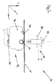
- FIG. 1 In a highly schematic manner, a slitter-winder 1 according to the invention is shown, which has an unwinding device 2 in the left-hand image area, in which a paper or board web M can be unwound from a mother roll 3.
- the paper or board web M is then guided by a longitudinal separation section 4, which is realized in the example shown as a longitudinal cutting device with positionable in y-direction format selection knife pairs 23, each pair of knives 23 by a driven disc-shaped upper or cutting blade 16 and a revolving lower - or pot knife 17 is formed.
- the longitudinal cutting section 4 is bounded in the x-direction by a front and a rear guide roller 11, which can of course also consist of individual segments.
- the paper or board web M is then in a further course in a, formed from two axially parallel support rollers 18,19, formed winding bed 6 feasible in the y-direction frontally juxtaposed partial web or finished rolls 7 are formed.
- At least one of the two support rollers 18, 19 can be driven.
- both support rollers 18,19 are driven and are connected via a common control and / or regulating device 20 in connection.
- a common control and / or regulating device 20 in connection.
- it has proven useful if the speed in the running direction x of the paper or board web M first support roller 18 and the second support roller 19 is torque-controlled.
- an elastic storage at least one support roller 18,19 is conceivable.
- the axes 21, 22 of the support rollers 18, 19 may be mounted at different height levels in the z direction.
- the support rollers 18,19 may have different diameters.
- At least one of the two support rollers 18, 19 also have a coating or casing which becomes effective on the paper or board web M, while, for example, the other support roller 18, 19 is designed as a steel roller.
- at least one of the support rollers 18, 19 may comprise a passive or active damping or a repayment element.
- winding cores 15 'arranged in alignment one behind the other are to correspond in their axial extent to the spacing of two adjacent pairs of blades 23 of the longitudinal dividing section 4.
- the cores 15 ' may preferably consist of cardboard or plastic.
- the most common diameter parameters in the market are 75 mm and 150 mm.
- the illustrated roll slitting machine 1 has a pressure roller device 24.
- the support rollers 18, 19 and the Antikwalzensegmente 25 of Andruckwalzen listening 24 are collectively referred to as winding rollers, by means of the Operabahn- or finished rolling 7 are formed and during each winding process together with these form a winding system 8, in mutually outgoing vibrations mutually Act.
- At least two of the at least two partial web rolls or finished rolls 7 forming side by side are connected to one another for the further course of the winding process by a bridging of the separating gap limited in their length (X).
- X the length of the section 27
- the length of the section 27 may vary depending on Execution of a slitter according to the invention 1 always be the same size.
- the slitter-winder 1 has an output device 32, which is designed such that the length of the section or sections 27 can be selected.
- a preferred dispensing device 32 comprises a housing 34 in which a path of defined length can be unwound from a spool to form connecting elements. It is preferred that the dispensing device 32, preferably along a guide 35 synchronously to the separating means, here the knife pairs 23 on the transverse direction (Y) of the slitter 1 positionable.
- this separation device and output device can also form a structural unit or, as shown here, be arranged spatially separated.
- the length of the respective section 27 corresponding to the instantaneous diameter D of the forming Operabahn- or finished rolling 7 and the current winding speed V is adaptable such that a compound of the adjacent Part track rollers 7 over 1 to 20 winding layers, preferably over 1 to 10 winding layers, very preferably over 2 to 5 winding layers results.
- the winding layers do not have to be reached in integer steps.
- the winding layers are not completely connected in itself, but that the longitudinal separation process is interrupted in short successive periods and resumed.
- FIG. 5 schematically illustrated connection it is then achievable that form, for example, two free spaces F within the connecting portion 27, which, starting from the partial web or finished rolling center, opposite, so form a common escape with the winding tube 15 '.
- the free spaces F a clearance forming slightly larger than the diameter of the used winding tube 15 ', so that a separation medium, such as a blade 28, is inserted into the free space F, and the connection is separable from the inside out.
- a winding tube 15 ' which may have been elongated under the winding load during the winding process, ie, will not be injured or hinder the separation process either.
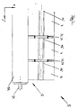
- FIG. 2 an exemplary embodiment of a designed as an application device means 31 is shown, which has an output device 32 and a pressing device 33. Output device 32 and pressing device 33 are synchronous with their associated, in FIG. 1 illustrated pair of knives 23 positionable in the Y direction.
- a guide 35 in the form of a dovetail guide is exemplarily shown on the underside of the housing 34 of the dispensing device 31.
- the guide 35 may take any, and preferably a configuration known to those skilled in the art with the known configurations for positioning knife pairs on roll cutting devices.
- the housing 34 of the dispensing device 32 provides a supply roll, not shown in greater detail, of which an adhesion promoter 37 can be acted upon or already acted upon, strip-shaped connecting means, from which connecting elements 36 can be produced by application to the sections 27 to be joined of the partial webs M 'and transverse cutting ,
- the pressing device 33 is for rapid mobility with two electromagnets 29 in operative connection and seen in the z direction between two predetermined by the two electromagnets 29 positions reversible, the pressing device 33 with the paper or board webs to be connected M in contact and about the output device 32 comes into operative connection.
- the other position P ' represents the waiting position.
- the entire process takes place within one second, more preferably even fractions of a second.
- a web stabilizer 10 is provided.
- Auswerfer wornen 14 of which in the illustrated side view, only the foremost is recognizable, along the Y direction corresponding to the individual longitudinal separation devices of the longitudinal separation section 4 can be positioned and act on ejection, that is, exactly when ejecting or rolling, the finished rolls 7 on the joints between two adjacent and inventively connected finished rollers 7.
- This tension the joints and can be separated in a suitable manner to form a particularly accurate and clean separation or cutting edge of each other. It is economically advantageous that no additional production time is required by the temporal overlap of the ejection process and the separation process and high efficiency of the slitter-winder 1 is ensured.
- This second device for separating the connected finished rolls is essentially an intermediate storage area 38 in which preferably finished rolls which have a connection with time-dependent strength are temporarily stored.
- the time interval of such connections is preferably set to the duration of an average winding process.
- the finished rolls 7 then roll down after release under their own weight a slope 39 and are separated by individually controllable stops 40.
Landscapes
- Replacement Of Web Rolls (AREA)
- Winding Of Webs (AREA)
Applications Claiming Priority (1)
| Application Number | Priority Date | Filing Date | Title |
|---|---|---|---|
| DE201010041718 DE102010041718A1 (de) | 2010-09-30 | 2010-09-30 | Wickelverfahren und Rollenschneidvorrichtung |
Publications (2)
| Publication Number | Publication Date |
|---|---|
| EP2436628A2 true EP2436628A2 (fr) | 2012-04-04 |
| EP2436628A3 EP2436628A3 (fr) | 2014-07-09 |
Family
ID=44720676
Family Applications (1)
| Application Number | Title | Priority Date | Filing Date |
|---|---|---|---|
| EP11182660.8A Withdrawn EP2436628A3 (fr) | 2010-09-30 | 2011-09-26 | Procédé d'enroulement et dispositif de découpage de rouleaux |
Country Status (2)
| Country | Link |
|---|---|
| EP (1) | EP2436628A3 (fr) |
| DE (1) | DE102010041718A1 (fr) |
Cited By (1)
| Publication number | Priority date | Publication date | Assignee | Title |
|---|---|---|---|---|
| CN115258226A (zh) * | 2022-07-05 | 2022-11-01 | 钢铁研究总院有限公司 | 一种焊丝分层包装装置及方法及分层盘状焊丝 |
Citations (1)
| Publication number | Priority date | Publication date | Assignee | Title |
|---|---|---|---|---|
| DE10160320A1 (de) | 2000-12-18 | 2002-11-14 | Henkel Kgaa | Selbstauflösendes Laminat |
Family Cites Families (8)
| Publication number | Priority date | Publication date | Assignee | Title |
|---|---|---|---|---|
| US1238356A (en) * | 1917-03-03 | 1917-08-28 | Joseph Joseph & Brothers Company | Wadding. |
| US1779578A (en) * | 1929-10-24 | 1930-10-28 | Clarence B Andersen | Method of forming paper rolls |
| US4170691A (en) * | 1975-09-11 | 1979-10-09 | Rogers J W | Steel metal web handling method, apparatus, and coil construct |
| US4304371A (en) * | 1979-07-09 | 1981-12-08 | Rogers J W | Peeling tool for integrated strip in a sheet metal coil construct |
| US4267984A (en) * | 1980-03-13 | 1981-05-19 | United States Steel Corporation | Method and apparatus for separating strip coil from wound construct by rotation |
| US4431141A (en) * | 1982-06-10 | 1984-02-14 | Crown Zellerbach Corporation | Method of making a roll paper product |
| US6935080B2 (en) * | 2001-02-13 | 2005-08-30 | Johns Manville International, Inc. | Pre-cut fibrous insulation for custom fitting wall cavities of different widths |
| DE102005000076A1 (de) * | 2005-06-15 | 2006-12-21 | Voith Patent Gmbh | Rollenvorrichtung und Verfahren zum gleichzeitigen Aufwickeln von mehreren nebeneinander laufenden Teil-Materialbahnen |
-
2010
- 2010-09-30 DE DE201010041718 patent/DE102010041718A1/de not_active Withdrawn
-
2011
- 2011-09-26 EP EP11182660.8A patent/EP2436628A3/fr not_active Withdrawn
Patent Citations (1)
| Publication number | Priority date | Publication date | Assignee | Title |
|---|---|---|---|---|
| DE10160320A1 (de) | 2000-12-18 | 2002-11-14 | Henkel Kgaa | Selbstauflösendes Laminat |
Cited By (2)
| Publication number | Priority date | Publication date | Assignee | Title |
|---|---|---|---|---|
| CN115258226A (zh) * | 2022-07-05 | 2022-11-01 | 钢铁研究总院有限公司 | 一种焊丝分层包装装置及方法及分层盘状焊丝 |
| CN115258226B (zh) * | 2022-07-05 | 2023-10-31 | 钢铁研究总院有限公司 | 一种焊丝分层包装装置及方法及分层盘状焊丝 |
Also Published As
| Publication number | Publication date |
|---|---|
| DE102010041718A1 (de) | 2012-04-05 |
| EP2436628A3 (fr) | 2014-07-09 |
Similar Documents
| Publication | Publication Date | Title |
|---|---|---|
| DE60317813T2 (de) | Verfahren zur herstellung von bahnmaterialrollen und eine das verfahren durchführende wickelmaschine | |
| DE60309162T2 (de) | Vorrichtung und verfahren zur herstellung von wickeln aus bahnförmigem material | |
| DE3522271A1 (de) | Vorrichtung zum aufwickeln einer gutbahn | |
| EP2295356B1 (fr) | Procédé et dispositif destinés au remplacement de bobines d'enroulement | |
| EP0744365A2 (fr) | Méthode pour changer le rouleau dans une machine à enrouler et machine à enrouler pour l'application de cette méthode | |
| AT505976B1 (de) | Verfahren in verbindung mit einem rollapparat einer faserbahnmaschine | |
| EP2803609B1 (fr) | Machine d'enroulement de matériaux en forme de bande | |
| EP0352564B1 (fr) | Procédé et dispositif de manipulation et de traitement ultérieur d'une bande du type en nid d'abeilles | |
| EP2436626A2 (fr) | Dispositif d'enroulement de rouleaux et procédé de fabrication de rouleaux d'enroulement | |
| EP2223876B1 (fr) | Agencement de bobineuses-refendeuses et procédé de fonctionnement d'un agencement de bobineuses-refendeuses | |
| DE202015105607U1 (de) | Vorrichtung zum Aufwickeln einer Faserbahn | |
| DE102019105485A1 (de) | Rollenschneidmaschinen-Antrieb | |
| EP3544438B1 (fr) | Méthode et appareil pour rouler un morceau de pâte et une feuille de séparation | |
| DE102010041718A1 (de) | Wickelverfahren und Rollenschneidvorrichtung | |
| EP1179630B1 (fr) | Procédé et dispositif pour la production de rouleaux de papier | |
| AT506494B1 (de) | Verfahren zum aufwickeln einer papierbahn | |
| EP2436627A2 (fr) | Procédé d'enroulement et machine de découpage de rouleaux | |
| WO2015028165A1 (fr) | Dispositif de dévidage de rouleaux de bandes continues de matière fibreuse et procédé de bobinage | |
| DE102017105298B4 (de) | Konfektionierungsanlage | |
| DE60002987T2 (de) | Verfahren und vorrichtung zum aufwickeln einer papierbahn | |
| EP1657194B1 (fr) | Dispositif d'enroulage de bobines et procédé pour l'enroulement de bobines | |
| EP1733983B1 (fr) | Méthode pour produire un raccordement sur une bobine et dispositif pour enrouler un materiau en bande sur une bobine | |
| DE19720174B4 (de) | Kalander | |
| EP2082982A2 (fr) | Dispositif d'enroulement | |
| EP1897831A2 (fr) | Procédé destiné au changement de rouleau dans un dispositif d'enroulement de rouleaux et dispositif d'enroulement de rouleaux pour l'enroulement d'une bande de matériau |
Legal Events
| Date | Code | Title | Description |
|---|---|---|---|
| PUAI | Public reference made under article 153(3) epc to a published international application that has entered the european phase |
Free format text: ORIGINAL CODE: 0009012 |
|
| AK | Designated contracting states |
Kind code of ref document: A2 Designated state(s): AL AT BE BG CH CY CZ DE DK EE ES FI FR GB GR HR HU IE IS IT LI LT LU LV MC MK MT NL NO PL PT RO RS SE SI SK SM TR |
|
| AX | Request for extension of the european patent |
Extension state: BA ME |
|
| PUAL | Search report despatched |
Free format text: ORIGINAL CODE: 0009013 |
|
| AK | Designated contracting states |
Kind code of ref document: A3 Designated state(s): AL AT BE BG CH CY CZ DE DK EE ES FI FR GB GR HR HU IE IS IT LI LT LU LV MC MK MT NL NO PL PT RO RS SE SI SK SM TR |
|
| AX | Request for extension of the european patent |
Extension state: BA ME |
|
| RIC1 | Information provided on ipc code assigned before grant |
Ipc: B65H 18/20 20060101AFI20140605BHEP Ipc: B65H 18/28 20060101ALI20140605BHEP |
|
| STAA | Information on the status of an ep patent application or granted ep patent |
Free format text: STATUS: THE APPLICATION IS DEEMED TO BE WITHDRAWN |
|
| 18D | Application deemed to be withdrawn |
Effective date: 20140401 |