EP2436632A1 - Dispositif de retenue pour un pistolet à aspiration de produit à enrouler - Google Patents
Dispositif de retenue pour un pistolet à aspiration de produit à enrouler Download PDFInfo
- Publication number
- EP2436632A1 EP2436632A1 EP10186377A EP10186377A EP2436632A1 EP 2436632 A1 EP2436632 A1 EP 2436632A1 EP 10186377 A EP10186377 A EP 10186377A EP 10186377 A EP10186377 A EP 10186377A EP 2436632 A1 EP2436632 A1 EP 2436632A1
- Authority
- EP
- European Patent Office
- Prior art keywords
- spulgut
- holding device
- suction gun
- spulguts
- receptacle
- Prior art date
- Legal status (The legal status is an assumption and is not a legal conclusion. Google has not performed a legal analysis and makes no representation as to the accuracy of the status listed.)
- Granted
Links
Images


Classifications
-
- B—PERFORMING OPERATIONS; TRANSPORTING
- B65—CONVEYING; PACKING; STORING; HANDLING THIN OR FILAMENTARY MATERIAL
- B65H—HANDLING THIN OR FILAMENTARY MATERIAL, e.g. SHEETS, WEBS, CABLES
- B65H54/00—Winding, coiling, or depositing filamentary material
- B65H54/86—Arrangements for taking-up waste material before or after winding or depositing
- B65H54/88—Arrangements for taking-up waste material before or after winding or depositing by means of pneumatic arrangements, e.g. suction guns
-
- B—PERFORMING OPERATIONS; TRANSPORTING
- B65—CONVEYING; PACKING; STORING; HANDLING THIN OR FILAMENTARY MATERIAL
- B65H—HANDLING THIN OR FILAMENTARY MATERIAL, e.g. SHEETS, WEBS, CABLES
- B65H2701/00—Handled material; Storage means
- B65H2701/30—Handled filamentary material
- B65H2701/31—Textiles threads or artificial strands of filaments
Definitions
- the invention relates to a holding device for a Spulgut suction gun. Furthermore, the invention relates to a holding device with such a holding device and a winding machine with a holding device for a Spulgut suction gun. The invention also relates to a method for transferring a Spulguts at the end of a winding process of a first coil on a winding station of a winder to a second spool, which is co-wound on the same winding station of the winder, wherein a Spulgut suction gun and a holding device for this are used.
- Spool material suction guns are known, which are used for handling a Spulguts in the production of the Spulguts and the winding of the Spulguts by a winder insert.
- a sucking air flow is brought about by which forces can be exerted on the Spulgut, the Spulgut can be caught in the region of a suction opening of the Spulgut-suction gun and / or the Spulgut with the air flow in an opening, a channel or a Receptacle of Spulgut suction gun "sucked" can be.
- these functions fulfilling suction devices are referred to as "Spulgut suction gun” regardless of whether they are designed as a kind of "gun” or in other structural design.
- Spool material suction guns can be used, for example, if a disturbance results in a winding machine, so that a continuous material produced in a continuous production process can not be removed continuously by the winding machine. In this case, the Spulgut can be sucked off continuously via the Spulgut suction gun. If a material to be spooled is located in the intake area of a spool material suction gun, the product to be spooled can also be supplied to a desired location via the spool material suction gun.
- the Spulgut the spooling machine can be supplied via the Spulgut-suction gun and, for example, a suitable catching a rotating spindle of the winder or a catcher of a driven by a spindle sleeve are supplied.
- Such Spulgut suction gun is for example off DE-OS 19 36 916 known, wherein the present invention can be used in connection with any type of Spulgut suction guns use.
- WO 2005/019081 A1 describes a winding machine, in which successively wound at a winding station coils.
- the winding material wound here is threads or tapes, for example a stretched single-layer or multi-layer plastic tape.
- the material to be spooled passes over a deflecting roller rotating about a stationary axis, a spring-supported dancer roller and a further deflection roller with fixed rotational axis to form a Spulgutleitmaschine.
- the Spulgut over a supported on the Spulgutleitmaschine deflection here a straight or curved trained overflow bar, to a traversing, which can be moved depending on the desired laying pattern for the Spulgut on the coil to be created any parallel to a rotation axis of the coil.
- the material to be wiped passes to a pressure roller, by means of which the wadding is applied with a contact pressure to a spindle or a sleeve carried by the spindle or already created windings.
- the Spulgutleitwerk with pressure roller, Changierspulgut concerned and deflection is pivotable about an axis which is oriented parallel to the axis of rotation of the coil.
- the spool is decelerated and any locking of the spool on the spindle is eliminated, thereby allowing the spool to be removed from the spindle. It can then be applied to the spindle a new empty sleeve, which is then optionally locked with the spindle and is rotated by them.
- the Spulgut suction gun can then be done such a handling of the Spulguts the Spulgut the empty shell or a suitable catching device of the sleeve or the spindle is supplied. Then the Spulgut between spindle or sleeve or second coil and Spulgut suction gun is severed, so that the winding process for the second coil can begin.
- the spatial movement of the Spulgut suction gun which must first catch the Spulgut between traversing and Changierspulgutinsta, then holds the Spulgut during the first cutting, then at a remote location the Spulgut a catching device of the spindle or sleeve of the second coil supplies and then the second cutting is also made at the discretion of the user.
- the present invention has for its object to provide a holding device and a holding device and a winder with such a holding device, which simplifies the change of the winding process of a first coil to a second coil at a winding station of a winder and / or makes less error prone. Furthermore, the invention has for its object to propose a simplified method for transferring a Spulguts at the end of a winding process of a first coil to a second coil, which is improved in particular with regard to process reliability and manual effort.
- the object of the invention is achieved with a holding device with the features of independent claim 1. Further embodiments of such a holding device according to the invention will become apparent from the dependent claims 2-13. Another solution to the problem underlying the invention is a holding device according to claim 14. A further solution of the invention is based task is given by a winder with the features of claim 15. Another solution of the invention underlying object is given by A further embodiment of such a method results in accordance with the dependent claims 17 and 18.
- a holding device for a winding material suction gun is used.
- This fixture specifies a defined location at which the operator can arrange the Spulgut-suction gun, can remove the hands of the Spulgut-suction gun and, for example, after a few steps, then again record the Spulgut-suction.
- the Spulgut suction gun can be kept in an absorbent state, in which this so receives continuously supplied Spulgut.
- the holding device according to the invention has an arbitrarily shaped receptacle for the Spulgut suction gun.
- the recording here is an introduction for the Spulgut suction gun.
- the holding device according to the invention has a fastening element by means of which the holding device can be fastened to a winding machine at a defined position and in a predetermined orientation.
- the holding device can be attached via the fastening element, for example, to a Spulgutleittechnik or to a housing of the winder.
- the attachment element of the holding device may be a mounting flange, a mounting carrier, bores, elongated holes, threads or the like.
- the holding device has a guide member.
- This guide member defines an entrance area of the Spulguts in the holding device.
- the guide member thus holds the Spulgut in the desired entry area of the holding device when the Spulgut suction gun is removed from the holding device and is moved freely outside the same, for example in the direction of the spindle to perform the change.
- the position of the entry region is selected in the holding device such that it is ensured that upstream of the entry region, the Spulgut not any deflection means, pulleys u. ⁇ . Leave, whereby the problems explained above are eliminated.
- the holding device has a Spulgut output slot. This is formed open against the insertion of the Spulgut suction gun into the receptacle of the holding device.
- the Spulgut output slot opens into the opening of the holding device, through which the Spulgut-suction gun is inserted into the receptacle.
- the Spulgut suction gun could not be removed from the holding device without the Spulgut exit slot according to the invention and moved in the direction of the spindle of the winder, without that the material to be spooled would be deflected several times in the holding device, which could lead to impairments of the Spulguts up to a rupture of the Spulguts.
- the Spulgut output slot allows the Spulgut suction gun is taken with this sucked Spulgut from the fixture and with the movement of the Spulgut suction gun in the direction of the spindle Spulgut at least without contact of the Spulguts with the holding device on the spindle side facing the holding device can pass.
- the Spulgut output slot allows the Spulgut suction gun can be removed with this incoming Spulgut from the holding device and can be moved outside the same without an excessive number of contact points with the holding device or deflection exists.
- the Spulgut output slot is formed continuously and open on both sides. It is also possible that the holding device is open on both sides, so that the Spulgut suction gun can be inserted through an opening in the holding device and can protrude in extreme cases on the opposite side of the holding device. The Spulgut exit slot can then connect the two openings mentioned together. With removal of the Spulgut suction gun, the suction opening with her incoming Spulgut withdrawn through the recording, in which case for the free movement of the Spulgut suction gun outside of the holding device, the Spulgut depending on the position of the Spulgut suction gun along the Spulgut exit slot "wander" can.
- the receptacle and the extent of the holding device are dimensioned such that in the receptacle inserted state of the Spulgut suction gun, the suction opening of the Spulgut suction gun is arranged in a Spulgut barn dawnsraum the holding device.
- the Spulgut-passage space has transverse to the direction of insertion of the Spulgut suction gun openings.
- the wad may pass through the apertures and the wadding passage space without any contact with the retainer.
- the holding device may be formed closed in the insertion behind the Spulgut.
- said openings are formed with the Spulgut output slot and the guide member or these open into one another.
- the fastening element and the receptacle are dimensioned and oriented such that the insertion direction of the receptacle for the Spulgut suction gun corresponds to the traversing direction of a traversing Spulgut concernss.
- This embodiment is based on the knowledge that it may be uncertain where the traversing spool guide is located at the end of the winding process for the first spool.
- the insertion direction of the holding device for the winding material suction gun is oriented parallel to the traversing direction, a different position of the traversing yarn guide towards the end of the winding process merely causes an interaction between the winding material suction gun and the winding material to be produced for different insertion depths of the winding suction gun into the receptacle is, but in any case, the suction opening of the Spulgut suction gun the Spulgut "hits". As a result, the process reliability can be increased.
- the openings of the Spulgut-guide space in a traverse plane extensions which are greater than the maximum movement of the Spulguts in the region of the holding device due to the movement of the traversing Spulgut concernss.
- This configuration has the consequence that unwanted contacts between Spulgut and holding device are excluded during the winding process and the traversing movement of the traversing Spulgut concernss that can lead to an increase in friction, a change in the thread tension and deterioration of Spulguts.
- the holding device has an insertion region for the receptacle, for example with an insertion element, an insertion bevel or an insertion funnel.
- the insertion area can simplify the insertion of the winding material suction gun for the operator and make it more reliable.
- the holding device is equipped with a cutting device for cutting the Spulguts according to a further proposal of the invention.
- This may be any desired cutting device, for example a knife, a heated separating element, a laser or the like.
- the holding device can be designed to be multifunctional, in that it is responsible for the severing of the product to be spooled in addition to the previously described holding and changing function as well as the guiding function for the product to be spooled.
- the cutting device comes movement controlled by the movement of the Spulgut suction gun in the recording to effect.
- a cutting blade can be actuated by means of the winding material suction gun, which is moved transversely to the winding material and cuts it. It is also possible that the Spulgut-suction gun "takes" the Spulgut and this presses against the cutting device with thereby brought about cutting the Spulguts.
- the invention proposes in a further embodiment, that the holding device is formed with a hollow housing open on one side.
- An interior of the hollow housing in this case forms the receptacle, in which case the Spulgut suction gun can be introduced through the open side of the housing in the recording.
- any holding device can be used within the scope of the invention, which makes it possible to insert the product for the first time, allows the product to be taken through, predetermines the entry region of the product by means of the guide element and avoids unnecessary deflections of the product to be taken during the change with the product exit slit.
- a housing of the holding device in the region of its lateral surface is equipped with an opening into the receptacle H-shaped opening.
- the two vertical leg and the horizontal leg of the H respectively Slits formed.
- the slot which forms the horizontal leg is oriented in the circumferential direction of the receptacle.
- the Spulgut can be introduced from above into the holding device via this slot.
- the slots forming the vertical limbs of the H are parallel to the insertion direction, that is to say preferably oriented in the traversing direction.
- the slot forming the horizontal limb of the H ends ends in the slots forming the vertical limbs of the H, so that after the introduction of the product to be winder through the first-mentioned slot, the wadding can enter the two slots forming the vertical limbs of the H. If the material to be winder passes through these two slots in the holding device, the slots allow the product to be moved during the traversing process without contact of the product with the boundaries of the slots.
- one of the slots which form the vertical leg of the H namely the slot which faces the spindle, the Spulgut exit slot, while the other one vertical leg of the H forming slot, namely the side facing away from the spindle slot, the guide member forms.
- the holding device (and the receptacle) can basically have any desired cross-section
- the holding device has an annular cross-section, which is preferably advantageous if at least part of the winding material suction gun extending into the receptacle has a tubular cross-section has.
- the holding device may also be equipped with an insertion, which may then be funnel-shaped.
- the cutting device for severing the Spulguts can be arranged in the change at any point inside and outside of the holding device.
- the cutting device is arranged in an end region of the Spulgut output slot. If, for example, with the Spulgut suction gun, the Spulgut brought into the end of the Spulgut output slots, this comes movement controlled to the plant to the cutter with the severing of the Spulguts.
- the Spulgut exit slot arranged on the spindle side facing the holding device is, the spindle facing the end of the Spulguts can be wound without further interaction with the holding device on the spool, while the "upstream" end of the Spulguts can be caught and sucked in the holding device by the Spulgut suction gun. While catching the Spulguts a Spulgutin between cutting device and entry of the Spulguts in the holding device form a suitable attack surface for the sucking air flow of the Spulgut suction gun.
- the holding device may have a sensor.
- the sensor can detect a position, a movement, a pressing force and / or a presence of a winding material suction gun in the recording. It is possible here that the sensor is designed as a digital switch or forms a continuous signal. The sensor signal of this sensor can then be supplied to a controller for controlling further operations of the winder.
- the operation of a cutting device influencing the Zumarin s for the Spulgut output side of the manufacturing process, influencing the drive of traversing device, the Spulgutleitwerks, the contact pressure of the pressure roller and / or the drive a Spindle or a pressure roller to drive the coil done.
- the change of the coil can be initiated by directly or delayed deceleration of the spindle or spool takes place and, for example, time-delayed or falls below a predetermined speed of the coil unlocking between coil and spindle. If the bobbin comes to a standstill, the operator can remove the first bobbin from the spindle without additional measures and attach a new sleeve to the spindle.
- control unit can automatically perform the locking of the sleeve and spindle and set the spindle in rotation in such a way that catching of the package can take place.
- a suitable detection device for the tension of the Spulguts in particular a detection device for a deflection of a spring-mounted dancer or a force sensor on a roller, thus can automatically detect the catch and the beginning of the winding process from an increase in the tension of the Spulguts, with which the winder in can change the usual control process for the winding of the coil, u. U. also with the onset of traversing movement. The user can then bring the Spulgut suction gun back into the receptacle and store there until the next change is pending.
- the aforementioned automation is merely an example of control and automation measures that can be brought about on the basis of a sensor signal.
- the holding device is designed for itself and is arranged on a Spulgutleitwerk or another component of the winding machine at a suitable point downstream of a deflection or a guide roller
- the holding device may also be part of a holding device, which also forms or carries the deflection , This simplifies assembly, since the unit provided with the holding device with integrated roller already predetermines the correct alignment of holding device, guide member and roller.
- a winder which has at least one winding station on which successive coils are wound with a Spulgut, so not the Spulgut is mutually wound on different spindles at different winding stations, as in particular for winding machines with several, arranged on a revolver winding stations is the case.
- the winding machine according to the invention has a traversing belt guide and a deflection, which is arranged upstream of the traversing yarn guide, that is "upstream" of this is arranged.
- a holding device of the type described above for a Spulgut suction gun is disposed between the traversing yarn guide and the deflection means, in particular a deflection roller. The Spulgut is passed (during the winding process) by the holding device.
- the Spulgut output slot of the holding device is arranged on the side facing the Changierspulgut enthusiasm, so that when removing the Spulgut suction gun and movement thereof in the direction of the spindle Spulgut a certain movement in the Spulgut exit slot can make without the Spulgut imperative The limits of the Spulgut-output slot comes to rest.
- the guide member of the holding device is arranged on the side facing the deflection, so that this holds on the right side of the holding device the Spulgut in an entry region, that ensures that the Spulgut the deflection independent of any movement of the Spulgut suction gun not leaves.
- Another object of the invention is based on a method with which a transfer of a product takes place at the end of a winding process of a first bobbin on a winding station of a winder to a second bobbin on the same winding station of the winder.
- a method u. U. initially at the end of the winding process of the first coil insertion of a Spulgut suction gun into a receptacle of a holding device for the Spulgut suction gun.
- the Spulgut suction gun is already stored during the winding process. Before, with or after this insertion, the Spulgut suction gun is activated.
- the guide is made such that the product to be spooled runs independently of the movement of the Spulguts with the Spulgut suction gun on the holding device upstream deflection, so this can not leave unintentionally.
- the application of the Spulguts done with the Spulgut suction gun for the beginning of the winding of the second coil wherein the application can be made directly to the spindle, provided that it forms the spool without additional sleeve, or takes place on a sleeve.
- This is followed by a second severing of the Spulguts, which then takes place the winding process for the second coil. It is understood that the order of said method steps may also be different than previously described.
- the Spulgut suction gun is moved in the receptacle and relative to a cutting device, so that the severing is motion-controlled by the Spulgut suction gun.
- the Spulgut suction gun is detected in the inventive method via a sensor, whether the Spulgut suction gun is in the recording, the Spulgut suction gun is inserted into the receptacle or is a thread tension increases or decreases, the Spulgut-suction gun from the recording is moved and / or the first cutting of the Spulguts takes place.
- the sensor signal of the sensor then takes place via a suitable control device an automatic control or regulation.
- a regulation of the feed rate of Spulguts done, a locking and / or unlocking the spindle with a sleeve or coil and / or a drive of the spindle done as has been partially already explained above.
- Fig. 1 shows a winder 1.
- the winder 1 is a Spulgut 2 fed.
- the Spulgut 2 is preferably prepared by a continuous production process and supplied continuously.
- the Spulgut 2 may be of any type, such as a thread or ribbon, twisted yarn, monofilament, a plastic tape u. in.
- components of the winder 1 can be done a treatment of the Spulguts 2, for example, an influence on the cross section thereof, in particular with a fanning, a deflection, a deflection with length compensation by a dancer role, a detection of the bias of the Spulguts u via a suitable measuring device. ä.
- the coil 7 is wound on a sleeve 8, which is offset by a spindle 9 in rotation.
- the longitudinal, movement or rotation axes of the guide roller 4, the pressure roller 6, the Coil 7, the sleeve 8 and the spindle 9 and the traversing direction 21 of the traversing yarn guide 5 are oriented parallel to each other. Notwithstanding the described embodiment, a drive of the coil 7 can not be done via a spindle, but via a driven drive roller. It is also possible that the coil 7 is wound directly on the spindle 9 without the interposition of the sleeve 8.
- the guide roller 4, the Changierspulgut investigating 5 and the pressure roller 6 are held by a Spulgutleitmaschine 10 while allowing a rotational movement of the guide roller 4 and pressure roller 6 and the traversing movement of the traversing.
- the Spulgutleittechnik 10 is movably mounted in the radial direction to the spindle.
- the Spulgutleittechnik 10 is pivoted about a pivot axis, which is vertical to the plane according to Fig. 1 is oriented.
- the specification of the contact pressure can be effected by the weight of the Spulgutleitmaschines 10 or via a suitable actuator.
- Fig. 2 shows in a highly schematic representation of the path of the Spulguts 2 between the deflection means 3 and the guide roller 4 and the traversing coil guide 5 for an embodiment of the invention.
- the Spulgut 2 passes through between the guide roller 4 and the traversing 5, the Spulgut 2 a holding device 11.
- the holding device 11 is held stationary for the illustrated embodiment of the Spulgutleitwerk 10.
- the Spulgut 2 is passed during the actual winding process as possible without contact with this by the holding device 11.
- the winding material 2 enters the holding device 11 in the region of a guide member 12.
- the guide member 12 is formed as an open-edged slot 13 with an edge opening 14, which is arranged on the deflection roller 4 facing side of the holding device 11.
- the first embodiment shown is the Spulgut exit slot 16 open on both sides with edge openings 17, 18.
- the holding device 11 forms a receptacle 19 for a Spulgut suction gun, which in an insertion 20 in the receptacle 19 can be introduced.
- the holding device 11 with a profile with constant Cross-section formed, wherein the cross section may be referred to in a first approximation as C-shaped.
- the insertion direction 20 and the slot 13 and the Spulgut exit slot 16 are oriented parallel to the traversing direction 21 of the traversing yarn guide 5.
- the guide member 12 and the slot 13 and the Spulgut exit slot 16 each form an opening 22, 23 of the Spulgut-passage space 15.
- the holding device 11 has an opening 25 through which the Spulgut suction gun into the receptacle 19 of the holding device 11 in the insertion direction 20 can be introduced and an opposite opening 24.
- a cutting device 26 is arranged, which is shown here in training with a cutting edge.
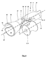
- Fig. 3 and 4 show a spatial representation of a second embodiment of a holding device 11. According to their function and / or structural design corresponding o. ⁇ . Constructive details are marked with the same reference numerals.
- the holding device 11 is formed with an example cast housing 27, which deviates from the embodiment according to Fig. 2
- the housing 27 has a first approximation tube-like geometry with an extension in the form of a funnel 28 in the direction of the opening 25.
- the receptacle 19 of the holding device 11 according to Fig. 3 and 4 Both the guide member 12 forming slot 13 and the Spulgut exit slot 16 are not open edge designed for this embodiment in the bottom portion 29, but rather edge-closed.
- the holding device 11 has a further slot 30, which is oriented transversely to the insertion direction 20, here in the circumferential direction of the housing 28.
- the slot 30 opens into an end region in the Spulgut exit slot 16 and in the other end in the slot 13.
- the slots 13, 30 and the Spulgut exit slot 16 in rough simplification an H-shaped opening, wherein the Spulgut exit slot 16 and the slot 13 form vertical leg of the H and the slot 30 forms the horizontal leg of the H.
- a sensor 31 is arranged, which passes through the housing 27 into the receptacle 19 for the illustrated embodiment.
- any type of sensor can be used, for example a mechanical switch actuated with the introduction of the winding material suction gun or a contactless sensor such as a Hall sensor, a reed contact or the like.
- the cutting device 26 is integrated into the holding device 11 for the second embodiment of the holding device 11.
- the cutting device 26 limits the Spulgut output slot 16 so that the Spulgut interacts with the cutting device 26 when this is forced along the Spulgut exit slot 16 in the direction of the bottom portion 29.
- the cutting device 26 is a plate-like cutting element, which is screwed by a fastening screw from the outside in a position to the holding device 11, in which the periphery forming a cutting edge slightly covers the Spulgut exit slot 16 from the outside.
- the deflection means 3 On the side facing away from the Changierspulgut ancestral 5 side of the holding device 11, the deflection means 3, here the guide roller 4 upstream, which is supported with a fixed predetermined axis of rotation 32 in the figures, not shown fasteners, support o. ⁇ .
- the housing 27 In the end region facing away from the opening 25 or in the bottom region 29, the housing 27 has suitable bores 33, via which the holding device can be coupled directly to the winding machine, in particular the Spulgutleitwerk 10 or coupled with the winding machine 1 with the interposition of other support elements.
- the coupling is made such that the axis of rotation 32 of the roller 4 is oriented so that from the lateral surface of the roller 4, the winding material through the slot 13, the Spulgut-passage space 15 and the Spulgut exit slot 16 without contact with the housing 28 to the traversing 5 can get.
- a fastening element 41 of the holding device 11 is formed.
- Fig. 5 schematically shows how the Spulgut 2 enters in a winder according to the invention without contact with the housing 27 in the region of the guide member 12, here the slot 13 in the Spulgut-passage chamber 15 and the holding device 11 leaves through the Spulgut exit slot 16 and rectilinear longitudinal axis as a result of the bias to the traversing 5 Wickierspulgutterrorism passes.
- Fig. 6 shows the laying of the thread in the laying triangle 34 as a result of the traversing movement 21 of the Changierspulgut concernss 5.
- the Spulgut 2 is passed without contact with the housing 27 through the slot 13 and the Spulgut exit slot 16, including the length of slot 13 and the Spulgut exit slot 16 is sized accordingly.
- this is the Spulgut in the slot 13 and the Spulgut exit slot 16 approximately at the place where opens into this slot 30.
- the winding material through the upper boundary of the slot 13 and the Spulgut exit slot 16 out.
- the product 2 still has a distance 35 from the cutting edge of the cutting device 26.
- Fig. 7 shows in a front view in viewing direction in the insertion direction 20, the holding device 11 with guide roller 4 and housing 27, wherein due to the edge opening 18, the Spulgut 2 can be seen in the Spulgut exit slot 16, while the entry of the Spulguts in the slot 13 in this view can be seen, since this slot 13 is closed at the edge.
- the end face 39 of the suction nozzle 37 with adjacent thereto Spulgut 2 pressed against a stopper member 40 to initiate the cutting operation by the cutter 26.
- This has the consequence that the friction acting on the Spulgut 2 between stop member 40 and end face 39 increases, which in turn has the consequence that increases the tension of the Spulguts 2 between the end face 39 and stop member 40 and the traversing 5.
- This increased tension has the consequence that the winding material 2 is pulled with a greater force against the cutting edge of the cutting device 26, whereby the severing is then caused.
- the funnel-shaped extension of the housing 27 forms an insertion region 42 for the winding material suction gun.
- a winder 1 is shown with only one winding station 43, where quite in a winder 1 and several winding stations can be operated in parallel.
- the holding device 11 according to the invention is used as an initial equipment for the winder 1 with their delivery to the customer.
- the holding device 11 according to the invention is marketed as a retrofit product for already previously distributed winding machines 1 and is used.
- a control device that a severing of the Spulguts 2 is carried out, which with a time delay or a deceleration of Spool 7 and / or unlocking the sleeve 8 can be triggered by the spindle 9.
- additional can be evaluated, an output signal of the sensor 31, by means of which it is detected how far the suction nozzle 37 of the winding material suction gun 44 is inserted into the receptacle 19.
- a holding device 45 can provide both the holding device 11 and the last of these upstream deflection means 3 as a compact structural unit.
- slot and "exit slot” any embodiment with rectilinear or curved longitudinal axis and the same or varying slot width is included.
- the Spulgut suction gun 44 rests locked or secured by friction.
Landscapes
- Replacement Of Web Rolls (AREA)
- Manufacture Of Motors, Generators (AREA)
- Replacing, Conveying, And Pick-Finding For Filamentary Materials (AREA)
Priority Applications (5)
| Application Number | Priority Date | Filing Date | Title |
|---|---|---|---|
| ES10186377T ES2397320T3 (es) | 2010-10-04 | 2010-10-04 | Dispositivo de sujección para una pistola de aspiración de material de bobinado |
| EP20100186377 EP2436632B1 (fr) | 2010-10-04 | 2010-10-04 | Dispositif de retenue pour un pistolet à aspiration de produit à enrouler |
| MX2011010241A MX2011010241A (es) | 2010-10-04 | 2011-09-29 | Dispositivo de sujecion para una pistola de aspiracion de material para bobina. |
| BRPI1106758A BRPI1106758A2 (pt) | 2010-10-04 | 2011-09-30 | dispositivo de retenção para uma pistola de aspiração de material bobinável |
| CN201110306718.XA CN102530649B (zh) | 2010-10-04 | 2011-10-08 | 用于绕线物品-吸枪的保持装置 |
Applications Claiming Priority (1)
| Application Number | Priority Date | Filing Date | Title |
|---|---|---|---|
| EP20100186377 EP2436632B1 (fr) | 2010-10-04 | 2010-10-04 | Dispositif de retenue pour un pistolet à aspiration de produit à enrouler |
Publications (3)
| Publication Number | Publication Date |
|---|---|
| EP2436632A1 true EP2436632A1 (fr) | 2012-04-04 |
| EP2436632A8 EP2436632A8 (fr) | 2012-06-20 |
| EP2436632B1 EP2436632B1 (fr) | 2012-11-14 |
Family
ID=43640268
Family Applications (1)
| Application Number | Title | Priority Date | Filing Date |
|---|---|---|---|
| EP20100186377 Active EP2436632B1 (fr) | 2010-10-04 | 2010-10-04 | Dispositif de retenue pour un pistolet à aspiration de produit à enrouler |
Country Status (5)
| Country | Link |
|---|---|
| EP (1) | EP2436632B1 (fr) |
| CN (1) | CN102530649B (fr) |
| BR (1) | BRPI1106758A2 (fr) |
| ES (1) | ES2397320T3 (fr) |
| MX (1) | MX2011010241A (fr) |
Cited By (1)
| Publication number | Priority date | Publication date | Assignee | Title |
|---|---|---|---|---|
| DE102015014297A1 (de) * | 2015-11-06 | 2017-05-11 | Saurer Germany Gmbh & Co. Kg | Verfahren und Vorrichtung zum Schneiden eines laufenden Fadens |
Families Citing this family (5)
| Publication number | Priority date | Publication date | Assignee | Title |
|---|---|---|---|---|
| DE102015013890A1 (de) * | 2015-10-28 | 2017-05-04 | Oerlikon Textile Gmbh & Co. Kg | Vorrichtung zum Anlegen mehrerer Fäden |
| DE102017001090A1 (de) * | 2017-02-07 | 2018-08-09 | Oerlikon Textile Gmbh & Co. Kg | Verfahren und Vorrichtung zur Bedienung mehrerer Spinnpositionen einer Schmelzspinnanlage |
| DE102018105933A1 (de) * | 2018-03-14 | 2019-09-19 | Maschinenfabrik Rieter Ag | Verfahren zum Bilden einer Fadenschlaufe und zum Separieren eines anzusetzenden Fadenstücks und eines abzuführenden Fadenstücks, Druckrollereinheit sowie Saugdüse |
| EP4477592A1 (fr) | 2023-06-07 | 2024-12-18 | Starlinger & Co Gesellschaft m.b.H. | Machine d'enroulement, butée de support de mécanisme de va-et-vient et procédé de fonctionnement d'une machine d'enroulement |
| EP4477593A1 (fr) | 2023-06-07 | 2024-12-18 | Starlinger & Co Gesellschaft m.b.H. | Dispositif d'enroulement, machine d'enroulement et procédé de fonctionnement d'une machine d'enroulement |
Citations (6)
| Publication number | Priority date | Publication date | Assignee | Title |
|---|---|---|---|---|
| DE1936916A1 (de) | 1969-07-19 | 1971-02-11 | Glanzstoff Ag | Injektor zum Absaugen von schnellbewegtem Fadenmaterial |
| US3564958A (en) * | 1967-07-17 | 1971-02-23 | Leesona Corp | Yarn handling apparatus |
| US3823631A (en) * | 1970-05-27 | 1974-07-16 | Ici Ltd | Apparatus for stringing a thread through a hole |
| JPH07257820A (ja) * | 1994-03-18 | 1995-10-09 | Toray Ind Inc | 巻糸体の糸端処理装置 |
| WO2005019081A1 (fr) | 2003-08-20 | 2005-03-03 | Starlinger & Co Gesellschaft M.B.H. | Bobineuse |
| DE102006061332A1 (de) * | 2006-12-22 | 2008-06-26 | Saurer Gmbh & Co. Kg | Vorrichtung zum Schmelzspinnen, Behandeln und Aufwickeln von synthetischen Fäden |
-
2010
- 2010-10-04 ES ES10186377T patent/ES2397320T3/es active Active
- 2010-10-04 EP EP20100186377 patent/EP2436632B1/fr active Active
-
2011
- 2011-09-29 MX MX2011010241A patent/MX2011010241A/es active IP Right Grant
- 2011-09-30 BR BRPI1106758A patent/BRPI1106758A2/pt not_active Application Discontinuation
- 2011-10-08 CN CN201110306718.XA patent/CN102530649B/zh active Active
Patent Citations (6)
| Publication number | Priority date | Publication date | Assignee | Title |
|---|---|---|---|---|
| US3564958A (en) * | 1967-07-17 | 1971-02-23 | Leesona Corp | Yarn handling apparatus |
| DE1936916A1 (de) | 1969-07-19 | 1971-02-11 | Glanzstoff Ag | Injektor zum Absaugen von schnellbewegtem Fadenmaterial |
| US3823631A (en) * | 1970-05-27 | 1974-07-16 | Ici Ltd | Apparatus for stringing a thread through a hole |
| JPH07257820A (ja) * | 1994-03-18 | 1995-10-09 | Toray Ind Inc | 巻糸体の糸端処理装置 |
| WO2005019081A1 (fr) | 2003-08-20 | 2005-03-03 | Starlinger & Co Gesellschaft M.B.H. | Bobineuse |
| DE102006061332A1 (de) * | 2006-12-22 | 2008-06-26 | Saurer Gmbh & Co. Kg | Vorrichtung zum Schmelzspinnen, Behandeln und Aufwickeln von synthetischen Fäden |
Cited By (1)
| Publication number | Priority date | Publication date | Assignee | Title |
|---|---|---|---|---|
| DE102015014297A1 (de) * | 2015-11-06 | 2017-05-11 | Saurer Germany Gmbh & Co. Kg | Verfahren und Vorrichtung zum Schneiden eines laufenden Fadens |
Also Published As
| Publication number | Publication date |
|---|---|
| CN102530649B (zh) | 2015-08-19 |
| BRPI1106758A2 (pt) | 2015-12-15 |
| CN102530649A (zh) | 2012-07-04 |
| EP2436632B1 (fr) | 2012-11-14 |
| MX2011010241A (es) | 2012-04-12 |
| ES2397320T3 (es) | 2013-03-06 |
| EP2436632A8 (fr) | 2012-06-20 |
Similar Documents
| Publication | Publication Date | Title |
|---|---|---|
| DE2615909C2 (fr) | ||
| EP2436632B1 (fr) | Dispositif de retenue pour un pistolet à aspiration de produit à enrouler | |
| DE102019129966B3 (de) | Vorrichtung und Verfahren zum Aufwickeln eines Fadens | |
| DE3805347A1 (de) | Aufspulmaschine | |
| EP1161397A1 (fr) | Procede et dispositif pour guider et couper un fil d'alimentation lors du changement de bobines | |
| DE19533833A1 (de) | Kreuzspulenwechseleinrichtung einer Kreuzspulen herstellenden Textilmaschine | |
| EP0367253A1 (fr) | Système d'échange pour un dispositif de mise en place d'un fil dans une machine à bobiner | |
| DE3833958A1 (de) | Vorrichtung zum aufspulen von drahtfoermigem gut auf zweiflanschige spulen | |
| DE19539936B4 (de) | Spulenfadenwickelvorrichtung zur Verwendung in einer Nähmaschine | |
| DE2543986A1 (de) | Verfahren und vorrichtung zur sicherung einer reservewicklung auf einer spulenhuelse | |
| DE2312609A1 (de) | Verfahren und vorrichtung zum auswechseln einer vollen kreuzspule gegen eine leere huelse | |
| DE102015010844A1 (de) | Verfahren zum Verbinden eines Ober- und eines Unterfadens an einer Spulstelle einer Spulmaschine und Spulstelle einer Spulmaschine | |
| DE102006006390A1 (de) | Fadenspleißvorrichtung für eine Kreuzspulen herstellende Textilmaschine | |
| EP3546406B1 (fr) | Procédé de formation d'une boucle de fil et de séparation d'une section de fil à utiliser et d'une section de fil à évacuer et unité de rouleaux presseurs | |
| CH686669A5 (de) | Verfahren und Vorrichtung zum Wickeln einer Fadenreserve. | |
| DE2710821B2 (de) | Fadenliefervorrichtung für Textilmaschinen | |
| DE10239334B4 (de) | Fadenspulmaschine mit einem Spannungsdetektor | |
| DE2657798A1 (de) | Vorrichtung zur uebergabe eines fadens an einen leeren wickelkoerper | |
| DE10201533A1 (de) | Offenend-Rotorspinnmaschine | |
| EP0411382A1 (fr) | Dispositif de préparation pour dévider l'extrémité de fil dans le bout du fuseau | |
| DE3235135C2 (fr) | ||
| DE4115339B4 (de) | Spulhülse | |
| DE3918946A1 (de) | Vorrichtung und verfahren zum anspinnen eines fadens an einer offenend-spinnvorrichtung | |
| EP3697710B1 (fr) | Dispositif de bobinage | |
| DE3843202C2 (de) | Aufspulmaschine |
Legal Events
| Date | Code | Title | Description |
|---|---|---|---|
| PUAI | Public reference made under article 153(3) epc to a published international application that has entered the european phase |
Free format text: ORIGINAL CODE: 0009012 |
|
| 17P | Request for examination filed |
Effective date: 20110421 |
|
| AK | Designated contracting states |
Kind code of ref document: A1 Designated state(s): AL AT BE BG CH CY CZ DE DK EE ES FI FR GB GR HR HU IE IS IT LI LT LU LV MC MK MT NL NO PL PT RO RS SE SI SK SM TR |
|
| AX | Request for extension of the european patent |
Extension state: BA ME |
|
| GRAJ | Information related to disapproval of communication of intention to grant by the applicant or resumption of examination proceedings by the epo deleted |
Free format text: ORIGINAL CODE: EPIDOSDIGR1 |
|
| GRAP | Despatch of communication of intention to grant a patent |
Free format text: ORIGINAL CODE: EPIDOSNIGR1 |
|
| RIC1 | Information provided on ipc code assigned before grant |
Ipc: B65H 54/88 20060101AFI20120522BHEP |
|
| GRAC | Information related to communication of intention to grant a patent modified |
Free format text: ORIGINAL CODE: EPIDOSCIGR1 |
|
| GRAP | Despatch of communication of intention to grant a patent |
Free format text: ORIGINAL CODE: EPIDOSNIGR1 |
|
| GRAS | Grant fee paid |
Free format text: ORIGINAL CODE: EPIDOSNIGR3 |
|
| GRAA | (expected) grant |
Free format text: ORIGINAL CODE: 0009210 |
|
| AK | Designated contracting states |
Kind code of ref document: B1 Designated state(s): AL AT BE BG CH CY CZ DE DK EE ES FI FR GB GR HR HU IE IS IT LI LT LU LV MC MK MT NL NO PL PT RO RS SE SI SK SM TR |
|
| REG | Reference to a national code |
Ref country code: GB Ref legal event code: FG4D Free format text: NOT ENGLISH |
|
| REG | Reference to a national code |
Ref country code: CH Ref legal event code: EP Ref country code: AT Ref legal event code: REF Ref document number: 583864 Country of ref document: AT Kind code of ref document: T Effective date: 20121115 |
|
| REG | Reference to a national code |
Ref country code: CH Ref legal event code: NV Representative=s name: RIEDERER HASLER AND PARTNER PATENTANWAELTE AG, LI |
|
| REG | Reference to a national code |
Ref country code: IE Ref legal event code: FG4D Free format text: LANGUAGE OF EP DOCUMENT: GERMAN |
|
| REG | Reference to a national code |
Ref country code: DE Ref legal event code: R096 Ref document number: 502010001628 Country of ref document: DE Effective date: 20130110 |
|
| REG | Reference to a national code |
Ref country code: ES Ref legal event code: FG2A Ref document number: 2397320 Country of ref document: ES Kind code of ref document: T3 Effective date: 20130306 |
|
| REG | Reference to a national code |
Ref country code: NL Ref legal event code: VDEP Effective date: 20121114 |
|
| REG | Reference to a national code |
Ref country code: LT Ref legal event code: MG4D |
|
| PG25 | Lapsed in a contracting state [announced via postgrant information from national office to epo] |
Ref country code: SE Free format text: LAPSE BECAUSE OF FAILURE TO SUBMIT A TRANSLATION OF THE DESCRIPTION OR TO PAY THE FEE WITHIN THE PRESCRIBED TIME-LIMIT Effective date: 20121114 Ref country code: FI Free format text: LAPSE BECAUSE OF FAILURE TO SUBMIT A TRANSLATION OF THE DESCRIPTION OR TO PAY THE FEE WITHIN THE PRESCRIBED TIME-LIMIT Effective date: 20121114 Ref country code: HR Free format text: LAPSE BECAUSE OF FAILURE TO SUBMIT A TRANSLATION OF THE DESCRIPTION OR TO PAY THE FEE WITHIN THE PRESCRIBED TIME-LIMIT Effective date: 20121114 Ref country code: NO Free format text: LAPSE BECAUSE OF FAILURE TO SUBMIT A TRANSLATION OF THE DESCRIPTION OR TO PAY THE FEE WITHIN THE PRESCRIBED TIME-LIMIT Effective date: 20130214 Ref country code: LT Free format text: LAPSE BECAUSE OF FAILURE TO SUBMIT A TRANSLATION OF THE DESCRIPTION OR TO PAY THE FEE WITHIN THE PRESCRIBED TIME-LIMIT Effective date: 20121114 |
|
| PG25 | Lapsed in a contracting state [announced via postgrant information from national office to epo] |
Ref country code: LV Free format text: LAPSE BECAUSE OF FAILURE TO SUBMIT A TRANSLATION OF THE DESCRIPTION OR TO PAY THE FEE WITHIN THE PRESCRIBED TIME-LIMIT Effective date: 20121114 Ref country code: GR Free format text: LAPSE BECAUSE OF FAILURE TO SUBMIT A TRANSLATION OF THE DESCRIPTION OR TO PAY THE FEE WITHIN THE PRESCRIBED TIME-LIMIT Effective date: 20130215 Ref country code: SI Free format text: LAPSE BECAUSE OF FAILURE TO SUBMIT A TRANSLATION OF THE DESCRIPTION OR TO PAY THE FEE WITHIN THE PRESCRIBED TIME-LIMIT Effective date: 20121114 Ref country code: PL Free format text: LAPSE BECAUSE OF FAILURE TO SUBMIT A TRANSLATION OF THE DESCRIPTION OR TO PAY THE FEE WITHIN THE PRESCRIBED TIME-LIMIT Effective date: 20121114 Ref country code: PT Free format text: LAPSE BECAUSE OF FAILURE TO SUBMIT A TRANSLATION OF THE DESCRIPTION OR TO PAY THE FEE WITHIN THE PRESCRIBED TIME-LIMIT Effective date: 20130314 |
|
| PG25 | Lapsed in a contracting state [announced via postgrant information from national office to epo] |
Ref country code: RS Free format text: LAPSE BECAUSE OF FAILURE TO SUBMIT A TRANSLATION OF THE DESCRIPTION OR TO PAY THE FEE WITHIN THE PRESCRIBED TIME-LIMIT Effective date: 20121114 Ref country code: DK Free format text: LAPSE BECAUSE OF FAILURE TO SUBMIT A TRANSLATION OF THE DESCRIPTION OR TO PAY THE FEE WITHIN THE PRESCRIBED TIME-LIMIT Effective date: 20121114 Ref country code: EE Free format text: LAPSE BECAUSE OF FAILURE TO SUBMIT A TRANSLATION OF THE DESCRIPTION OR TO PAY THE FEE WITHIN THE PRESCRIBED TIME-LIMIT Effective date: 20121114 Ref country code: BG Free format text: LAPSE BECAUSE OF FAILURE TO SUBMIT A TRANSLATION OF THE DESCRIPTION OR TO PAY THE FEE WITHIN THE PRESCRIBED TIME-LIMIT Effective date: 20130214 Ref country code: SK Free format text: LAPSE BECAUSE OF FAILURE TO SUBMIT A TRANSLATION OF THE DESCRIPTION OR TO PAY THE FEE WITHIN THE PRESCRIBED TIME-LIMIT Effective date: 20121114 |
|
| PG25 | Lapsed in a contracting state [announced via postgrant information from national office to epo] |
Ref country code: NL Free format text: LAPSE BECAUSE OF FAILURE TO SUBMIT A TRANSLATION OF THE DESCRIPTION OR TO PAY THE FEE WITHIN THE PRESCRIBED TIME-LIMIT Effective date: 20121114 Ref country code: RO Free format text: LAPSE BECAUSE OF FAILURE TO SUBMIT A TRANSLATION OF THE DESCRIPTION OR TO PAY THE FEE WITHIN THE PRESCRIBED TIME-LIMIT Effective date: 20121114 |
|
| PLBE | No opposition filed within time limit |
Free format text: ORIGINAL CODE: 0009261 |
|
| STAA | Information on the status of an ep patent application or granted ep patent |
Free format text: STATUS: NO OPPOSITION FILED WITHIN TIME LIMIT |
|
| 26N | No opposition filed |
Effective date: 20130815 |
|
| PG25 | Lapsed in a contracting state [announced via postgrant information from national office to epo] |
Ref country code: CY Free format text: LAPSE BECAUSE OF FAILURE TO SUBMIT A TRANSLATION OF THE DESCRIPTION OR TO PAY THE FEE WITHIN THE PRESCRIBED TIME-LIMIT Effective date: 20121114 |
|
| REG | Reference to a national code |
Ref country code: DE Ref legal event code: R097 Ref document number: 502010001628 Country of ref document: DE Effective date: 20130815 |
|
| BERE | Be: lapsed |
Owner name: STARLINGER & CO. -G. M.B.H. Effective date: 20131031 |
|
| PG25 | Lapsed in a contracting state [announced via postgrant information from national office to epo] |
Ref country code: MC Free format text: LAPSE BECAUSE OF FAILURE TO SUBMIT A TRANSLATION OF THE DESCRIPTION OR TO PAY THE FEE WITHIN THE PRESCRIBED TIME-LIMIT Effective date: 20121114 |
|
| REG | Reference to a national code |
Ref country code: IE Ref legal event code: MM4A |
|
| REG | Reference to a national code |
Ref country code: FR Ref legal event code: ST Effective date: 20140630 |
|
| PG25 | Lapsed in a contracting state [announced via postgrant information from national office to epo] |
Ref country code: FR Free format text: LAPSE BECAUSE OF NON-PAYMENT OF DUE FEES Effective date: 20131031 |
|
| PG25 | Lapsed in a contracting state [announced via postgrant information from national office to epo] |
Ref country code: BE Free format text: LAPSE BECAUSE OF NON-PAYMENT OF DUE FEES Effective date: 20131031 |
|
| PG25 | Lapsed in a contracting state [announced via postgrant information from national office to epo] |
Ref country code: IE Free format text: LAPSE BECAUSE OF NON-PAYMENT OF DUE FEES Effective date: 20131004 |
|
| PG25 | Lapsed in a contracting state [announced via postgrant information from national office to epo] |
Ref country code: SM Free format text: LAPSE BECAUSE OF FAILURE TO SUBMIT A TRANSLATION OF THE DESCRIPTION OR TO PAY THE FEE WITHIN THE PRESCRIBED TIME-LIMIT Effective date: 20121114 |
|
| GBPC | Gb: european patent ceased through non-payment of renewal fee |
Effective date: 20141004 |
|
| PG25 | Lapsed in a contracting state [announced via postgrant information from national office to epo] |
Ref country code: HU Free format text: LAPSE BECAUSE OF FAILURE TO SUBMIT A TRANSLATION OF THE DESCRIPTION OR TO PAY THE FEE WITHIN THE PRESCRIBED TIME-LIMIT; INVALID AB INITIO Effective date: 20101004 Ref country code: MK Free format text: LAPSE BECAUSE OF FAILURE TO SUBMIT A TRANSLATION OF THE DESCRIPTION OR TO PAY THE FEE WITHIN THE PRESCRIBED TIME-LIMIT Effective date: 20121114 Ref country code: LU Free format text: LAPSE BECAUSE OF NON-PAYMENT OF DUE FEES Effective date: 20131004 Ref country code: GB Free format text: LAPSE BECAUSE OF NON-PAYMENT OF DUE FEES Effective date: 20141004 |
|
| PG25 | Lapsed in a contracting state [announced via postgrant information from national office to epo] |
Ref country code: MT Free format text: LAPSE BECAUSE OF FAILURE TO SUBMIT A TRANSLATION OF THE DESCRIPTION OR TO PAY THE FEE WITHIN THE PRESCRIBED TIME-LIMIT Effective date: 20121114 |
|
| PG25 | Lapsed in a contracting state [announced via postgrant information from national office to epo] |
Ref country code: IS Free format text: LAPSE BECAUSE OF FAILURE TO SUBMIT A TRANSLATION OF THE DESCRIPTION OR TO PAY THE FEE WITHIN THE PRESCRIBED TIME-LIMIT Effective date: 20121114 |
|
| PG25 | Lapsed in a contracting state [announced via postgrant information from national office to epo] |
Ref country code: AL Free format text: LAPSE BECAUSE OF FAILURE TO SUBMIT A TRANSLATION OF THE DESCRIPTION OR TO PAY THE FEE WITHIN THE PRESCRIBED TIME-LIMIT Effective date: 20121114 |
|
| P01 | Opt-out of the competence of the unified patent court (upc) registered |
Effective date: 20230529 |
|
| PGFP | Annual fee paid to national office [announced via postgrant information from national office to epo] |
Ref country code: ES Payment date: 20231117 Year of fee payment: 14 |
|
| PGFP | Annual fee paid to national office [announced via postgrant information from national office to epo] |
Ref country code: TR Payment date: 20250925 Year of fee payment: 16 |
|
| PGFP | Annual fee paid to national office [announced via postgrant information from national office to epo] |
Ref country code: CZ Payment date: 20250919 Year of fee payment: 16 |
|
| REG | Reference to a national code |
Ref country code: CH Ref legal event code: U11 Free format text: ST27 STATUS EVENT CODE: U-0-0-U10-U11 (AS PROVIDED BY THE NATIONAL OFFICE) Effective date: 20251101 |
|
| REG | Reference to a national code |
Ref country code: ES Ref legal event code: FD2A Effective date: 20251126 |
|
| PGFP | Annual fee paid to national office [announced via postgrant information from national office to epo] |
Ref country code: DE Payment date: 20251020 Year of fee payment: 16 |
|
| PGFP | Annual fee paid to national office [announced via postgrant information from national office to epo] |
Ref country code: AT Payment date: 20251021 Year of fee payment: 16 |
|
| PGFP | Annual fee paid to national office [announced via postgrant information from national office to epo] |
Ref country code: IT Payment date: 20251031 Year of fee payment: 16 |
|
| PGFP | Annual fee paid to national office [announced via postgrant information from national office to epo] |
Ref country code: CH Payment date: 20251101 Year of fee payment: 16 |
|
| PG25 | Lapsed in a contracting state [announced via postgrant information from national office to epo] |
Ref country code: ES Free format text: LAPSE BECAUSE OF NON-PAYMENT OF DUE FEES Effective date: 20241005 |