EP2436963A2 - Appareil de réglage pour la commande d'un flux de fluide - Google Patents
Appareil de réglage pour la commande d'un flux de fluide Download PDFInfo
- Publication number
- EP2436963A2 EP2436963A2 EP11171658A EP11171658A EP2436963A2 EP 2436963 A2 EP2436963 A2 EP 2436963A2 EP 11171658 A EP11171658 A EP 11171658A EP 11171658 A EP11171658 A EP 11171658A EP 2436963 A2 EP2436963 A2 EP 2436963A2
- Authority
- EP
- European Patent Office
- Prior art keywords
- valve
- housing
- valve rod
- valve body
- actuating
- Prior art date
- Legal status (The legal status is an assumption and is not a legal conclusion. Google has not performed a legal analysis and makes no representation as to the accuracy of the status listed.)
- Withdrawn
Links
- 239000012530 fluid Substances 0.000 title claims description 31
- 230000001105 regulatory effect Effects 0.000 title description 3
- XEEYBQQBJWHFJM-UHFFFAOYSA-N Iron Chemical group [Fe] XEEYBQQBJWHFJM-UHFFFAOYSA-N 0.000 claims description 9
- 238000004891 communication Methods 0.000 claims description 3
- 230000001747 exhibiting effect Effects 0.000 claims 1
- 238000005259 measurement Methods 0.000 claims 1
- 238000000034 method Methods 0.000 description 5
- 230000001276 controlling effect Effects 0.000 description 4
- 210000003746 feather Anatomy 0.000 description 3
- 230000008569 process Effects 0.000 description 3
- 230000000694 effects Effects 0.000 description 2
- 229910052742 iron Inorganic materials 0.000 description 2
- 230000009471 action Effects 0.000 description 1
- 230000001419 dependent effect Effects 0.000 description 1
- 238000011161 development Methods 0.000 description 1
- 230000018109 developmental process Effects 0.000 description 1
- 230000004069 differentiation Effects 0.000 description 1
- 238000005553 drilling Methods 0.000 description 1
- 230000008030 elimination Effects 0.000 description 1
- 238000003379 elimination reaction Methods 0.000 description 1
- 230000007246 mechanism Effects 0.000 description 1
- 230000002093 peripheral effect Effects 0.000 description 1
- 230000036316 preload Effects 0.000 description 1
- 230000009467 reduction Effects 0.000 description 1
- 238000007789 sealing Methods 0.000 description 1
Images

Classifications
-
- F—MECHANICAL ENGINEERING; LIGHTING; HEATING; WEAPONS; BLASTING
- F16—ENGINEERING ELEMENTS AND UNITS; GENERAL MEASURES FOR PRODUCING AND MAINTAINING EFFECTIVE FUNCTIONING OF MACHINES OR INSTALLATIONS; THERMAL INSULATION IN GENERAL
- F16K—VALVES; TAPS; COCKS; ACTUATING-FLOATS; DEVICES FOR VENTING OR AERATING
- F16K31/00—Actuating devices; Operating means; Releasing devices
- F16K31/02—Actuating devices; Operating means; Releasing devices electric; magnetic
- F16K31/06—Actuating devices; Operating means; Releasing devices electric; magnetic using a magnet, e.g. diaphragm valves, cutting off by means of a liquid
- F16K31/08—Actuating devices; Operating means; Releasing devices electric; magnetic using a magnet, e.g. diaphragm valves, cutting off by means of a liquid using a permanent magnet
- F16K31/086—Actuating devices; Operating means; Releasing devices electric; magnetic using a magnet, e.g. diaphragm valves, cutting off by means of a liquid using a permanent magnet the magnet being movable and actuating a second magnet connected to the closing element
-
- F—MECHANICAL ENGINEERING; LIGHTING; HEATING; WEAPONS; BLASTING
- F16—ENGINEERING ELEMENTS AND UNITS; GENERAL MEASURES FOR PRODUCING AND MAINTAINING EFFECTIVE FUNCTIONING OF MACHINES OR INSTALLATIONS; THERMAL INSULATION IN GENERAL
- F16K—VALVES; TAPS; COCKS; ACTUATING-FLOATS; DEVICES FOR VENTING OR AERATING
- F16K27/00—Construction of housing; Use of materials therefor
- F16K27/02—Construction of housing; Use of materials therefor of lift valves
-
- F—MECHANICAL ENGINEERING; LIGHTING; HEATING; WEAPONS; BLASTING
- F16—ENGINEERING ELEMENTS AND UNITS; GENERAL MEASURES FOR PRODUCING AND MAINTAINING EFFECTIVE FUNCTIONING OF MACHINES OR INSTALLATIONS; THERMAL INSULATION IN GENERAL
- F16K—VALVES; TAPS; COCKS; ACTUATING-FLOATS; DEVICES FOR VENTING OR AERATING
- F16K31/00—Actuating devices; Operating means; Releasing devices
- F16K31/12—Actuating devices; Operating means; Releasing devices actuated by fluid
- F16K31/36—Actuating devices; Operating means; Releasing devices actuated by fluid in which fluid from the circuit is constantly supplied to the fluid motor
- F16K31/38—Actuating devices; Operating means; Releasing devices actuated by fluid in which fluid from the circuit is constantly supplied to the fluid motor in which the fluid works directly on both sides of the fluid motor, one side being connected by means of a restricted passage and the motor being actuated by operating a discharge from that side
- F16K31/383—Actuating devices; Operating means; Releasing devices actuated by fluid in which fluid from the circuit is constantly supplied to the fluid motor in which the fluid works directly on both sides of the fluid motor, one side being connected by means of a restricted passage and the motor being actuated by operating a discharge from that side the fluid acting on a piston
- F16K31/3835—Actuating devices; Operating means; Releasing devices actuated by fluid in which fluid from the circuit is constantly supplied to the fluid motor in which the fluid works directly on both sides of the fluid motor, one side being connected by means of a restricted passage and the motor being actuated by operating a discharge from that side the fluid acting on a piston the discharge being effected through the piston and being blockable by a mechanically-actuated member making contact with the piston
-
- F—MECHANICAL ENGINEERING; LIGHTING; HEATING; WEAPONS; BLASTING
- F16—ENGINEERING ELEMENTS AND UNITS; GENERAL MEASURES FOR PRODUCING AND MAINTAINING EFFECTIVE FUNCTIONING OF MACHINES OR INSTALLATIONS; THERMAL INSULATION IN GENERAL
- F16K—VALVES; TAPS; COCKS; ACTUATING-FLOATS; DEVICES FOR VENTING OR AERATING
- F16K31/00—Actuating devices; Operating means; Releasing devices
- F16K31/12—Actuating devices; Operating means; Releasing devices actuated by fluid
- F16K31/36—Actuating devices; Operating means; Releasing devices actuated by fluid in which fluid from the circuit is constantly supplied to the fluid motor
- F16K31/40—Actuating devices; Operating means; Releasing devices actuated by fluid in which fluid from the circuit is constantly supplied to the fluid motor with electrically-actuated member in the discharge of the motor
- F16K31/406—Actuating devices; Operating means; Releasing devices actuated by fluid in which fluid from the circuit is constantly supplied to the fluid motor with electrically-actuated member in the discharge of the motor acting on a piston
- F16K31/408—Actuating devices; Operating means; Releasing devices actuated by fluid in which fluid from the circuit is constantly supplied to the fluid motor with electrically-actuated member in the discharge of the motor acting on a piston the discharge being effected through the piston and being blockable by an electrically-actuated member making contact with the piston
Definitions
- the invention relates to a control device for controlling a fluid flow according to the specified in the preamble of claim 1.
- a dynamic seal is used to seal bushings, for example in the valve housing, by means of which a translational or rotational movement is introduced into the valve housing by means of a shaft. With the help of this shaft, the valve body is moved by different positions of the valve body, the desired throttle effect is achieved. Dynamic seals are subject to wear and other mechanisms that may leak process fluid into the surrounding atmosphere.
- the invention is based on the object, a control device for controlling a fluid flow according to the type specified in the preamble of claim 1 while avoiding the disadvantages mentioned in such a way that the risk of leakage and thus leakage of process fluid is reduced in the surrounding atmosphere.
- the control device for controlling a fluid flow comprises a basic housing with an inlet and a drain. Between the inlet and outlet in the base housing a valve seat is arranged. Furthermore, the actuating device comprises a valve body operatively engageable with the valve body and a valve rod for actuating the valve body and a device for actuating the valve rod.
- an additional housing is fluid-tightly arranged on the main housing in such a way that the basic and additional housing forms, with the exception of the inlet and outlet, a housing which is closed on all sides, completely encapsulated, having only one circumferential seal, the valve rod being free from execution, i.e. from the housing. is arranged completely inside the closed housing.
- the inventive design of the basic and additional housing as a closed housing and the inventive implementation-free arrangement of the valve rod in the interior of the closed housing an actuating device is provided in an advantageous manner that corresponding dynamic seals for sealing an extending into the valve housing valve rod no longer has , so that the risk of leakage due to a damaged dynamic seal is no longer possible now.
- the device for actuating the valve rod is arranged outside the closed housing and is non-contact with the valve rod in operative connection. This has the effect that the housing has no further opening for driving the valve rod, so that the risk of leakage is additionally reduced.
- the device for actuating the valve rod is designed such that it actuates the valve rod via a magnetic and / or electromagnetic force.
- valve rod to an iron core or a magnet, while outside of the closed housing, a reference to the housing displaceable outer magnet is arranged.
- a non-contact actuation of the valve rod can be initiated.
- This embodiment of the device for actuating the valve rod is characterized in particular by its constructive simplicity and reliability.
- the valve rod in turn has an iron core or a magnet, while outside of the closed housing, a fixedly mounted on the housing electromagnet is arranged.
- a fixedly mounted on the housing electromagnet By changing the current flow through the electromagnet, a different force is exerted on the valve rod, via which the non-contact actuation of the valve rod is controllable.
- the use of a permanently mounted on the housing electromagnet proves to be advantageous because a simplified structure is ensured due to the elimination of a relative movement between the outer magnet and the housing.
- the valve body is in operative connection with a drive arranged within the closed housing, the drive being fed by means of the fluid flowing through the actuating device.
- fluidically operated drives according to the prior art are possible as actuators, pneumatically as well as hydraulically actuated.
- a linear drive in principle - with a suitable deformation of the movement and part-turn actuators are conceivable.
- a fluidically actuated positioner according to the prior art is conceivable, which is housed within the closed housing in principle. The positioner would detect the position of the valve body and perform a corresponding position control.
- FIG. 1 A possible example of such a positioner shows Fig. 1 from DE 28 47 380 A1
- the lever 5 would have to be provided with a magnet whose applied force is controlled by an out-of-housing device as described above.
- the inflowing fluid in the valve inlet of the actuator according to the invention would act on the input 8.
- Input 3 would be omitted, the fluid flowing out of the nozzle 7 would be suitably transferred into the valve outlet of the actuator according to the invention.
- the valve rod is complete and the valve body partially guided in the housing and between the valve body and valve rod, a first and a second chamber are formed, which are in fluid communication with each other via a through hole, wherein the valve body associated with the first chamber via a through hole in the valve body is in fluidic contact with the inlet and associated with the valve rod second chamber via a Bore with the drain is in fluidic contact.
- the valve rod is arranged and designed such that via an actuation of the valve rod, the passage opening between the first and second chamber to open and close.
- the valve body is guided under spring tension in the housing.
- a return of the valve body is ensured in a simple manner.
- the passage opening has a larger diameter than the through hole.
- valve rod is guided biased by a spring element in the closed housing.
- the actuating device is preceded by a main valve.
- the main valve comprises a base and additional housing, wherein the base housing has an inlet and a drain and a valve seat arranged between inlet and outlet and the additional housing has a valve body operatively engageable valve body and a compensation chamber having an outlet opening.
- the valve body is partially guided under spring preload in the additional housing and the compensation chamber is in fluid contact with the inlet of the main valve via a through hole in the valve body.
- Acting as a pilot stage actuating device is in fluid contact with its inlet to the outlet opening of the main valve and its outlet with the flow of the main valve.
- the through hole in the valve body of the actuator and the passage opening between the first and second chambers of the actuator has a smaller diameter than the through hole in the valve body of the main valve and the outlet opening of the compensation chamber of the main valve. Since the pressure in the inlet of the actuator is equal to the inlet pressure of the main valve, the actuator has the same performance as the main valve. Further, since the flow through the main valve is regulated and the cross sections have been selected accordingly, advantageously the actuating force which the device for actuating the valve stem of the actuator has to be applied is significantly lower.
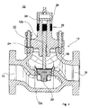
- Fig. 1 shows more or less schematically a generally designated by the reference numeral 10 actuating device for controlling a valve 10 flowing through the fluid.
- the actuator 10 includes a base housing 12a with an inlet 14 and a drain 16. Between inlet 14 and outlet 16, a valve seat 18 is arranged.
- the actuator 10 includes a valve body 20, which in turn is connected to a valve rod 22. About a lifting movement of the valve rod 22, the flow between the valve body 20 and valve seat 18 is controllable. The corresponding device for actuating the valve rod 22 will be described later.
- the actuator 10 has an additional housing 12b.
- the additional housing 12b fluid-tightly arranged on the base housing 12a, that the basic and additional housing 12a, 12b with the exception of the inlet and outlet 14, 16 a closed on all sides, fully enclosed, only a peripheral seal 24 having housing 12th form.
- the additional housing 12 b is also designed such that the valve rod 22 is completely arranged without implementation completely inside the closed housing 12.
- the already-mentioned device for actuating the valve rod in the present case comprises a magnet 26 fixedly connected to the valve rod 22 and an outer magnet 28 arranged outside the housing 12, which in turn is arranged displaceably via a frame element 30 to the housing 12.
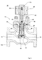
- the valve rod 22 is fixedly connected to an iron body 32 according to the second embodiment, so that in turn by a movement of the frame 30 with respect to the housing 12, a non-contact movement of the valve rod 22 is possible.
- the additional housing 12b formed such that the valve rod 22 is completely and the valve body 20 partially guided in the additional housing 12b.
- the valve rod 22 via a spring 34 and the valve body 20 are guided via a spring 36 under spring bias in the auxiliary housing 12b.
- a first chamber 38 and a second chamber 40 are formed, which are in fluid communication with each other via a passage opening 42. While the first chamber 38 is in fluidic contact with the inlet 14 via a through bore 44 introduced into the valve body 20, the second chamber 40 is in fluidic contact with the drain 16 via a bore 46.
- valve rod 22 is arranged and designed such that via an actuation of the valve rod 22, the passage opening 42 between the first and second chambers 38, 40 to open and close.
- the force required to actuate the valve rod 22 is reduced:
- the fluid is passed through the passage bore 44 in the valve body 20 into the first chamber 38 and thus onto the rear side of the valve body 20.
- the valve body 20 is free of forces.
- the valve body 22 with the full force of the spring 36 in the Valve seat 18 pressed.
- a movement of the valve body 20 can now be achieved that the pressure acting on the top of the valve body 20 pressure is reduced.
- the passage opening 42 between the first and second chambers 38, 40 is opened by a movement of the valve rod 22, so that fluid from the first chamber 38 via the passage opening 42 in the second chamber 40 and from there via the bore 46 to the drain 16 can flow.
- the ratio of the passage opening 42 to the through hole 44 is selected so that the passage opening 42 allows a much larger flow, so that with complete opening of the passage opening 42 an almost complete reduction of the pressure above the valve body 20 can be achieved.
- FIG. 3 illustrated third embodiment of the invention substantially corresponds to in Fig. 2 illustrated second embodiment. Unlike the in Fig. 2 shown second embodiment, only the device for actuating the valve rod is formed differently in the third embodiment.
- valve rod 22 is in turn fixedly connected to an iron core 32 or an inner magnet 26. Outside the housing 12, a solenoid 48 is fixedly connected to the housing. By changing the current flow, a different force is exerted on the valve rod 22 by the electromagnet 48.
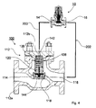
- control unit 10 is preceded by a main valve designated overall by the reference numeral 100. To avoid repetition is with respect to the structure of the actuator 10 to the above under Fig. 2 and 3 referenced.
- the main valve 100 comprises a base housing 112 a, which has an inlet 114 and a drain 116. Between the inlet 114 and the outlet 116, a valve seat 118 is arranged. Furthermore, the main valve 100 comprises an additional housing 112 b, which forms a housing 112 of the main valve 100 with the base housing 12 a.
- the additional housing 112b is designed in such a way that a valve body 120, which is in operative connection with the valve seat 118, is guided in regions in the additional housing 112b under the bias of a spring 136.
- the additional housing 112b has a compensation chamber 138 with an outlet opening 142.
- the outlet opening 142 is connected via a line 200 to the inlet 14 of the actuator 10 and the outlet 16 of the actuator 10 via a line 202 connected to the outlet 116 of the main valve 100.
- both the diameter of the through hole 44 in the valve body 20 of the actuator 10 with respect to the diameter of the through hole 144 in the valve body 120 of the main valve and the diameter output port 142 in the housing 112b of the main valve 100 with respect to the passage opening 142 between the first and second chamber 36, 38 of the actuator designed much lower.
- the actuator 10 Since the pressure in the inlet 16 of the actuator 10 is equal to the inlet pressure of the main valve 100, the actuator 10 has the same power as the main valve 100. Further, since the flow through the main valve 100 is regulated and the cross-sections have been selected accordingly, is in an advantageous manner the actuation force, which must be applied to the device for actuating the valve rod 22 of the actuator 10, significantly lower.
Landscapes
- Engineering & Computer Science (AREA)
- General Engineering & Computer Science (AREA)
- Mechanical Engineering (AREA)
- Magnetically Actuated Valves (AREA)
- Lift Valve (AREA)
- Preventing Unauthorised Actuation Of Valves (AREA)
Applications Claiming Priority (1)
| Application Number | Priority Date | Filing Date | Title |
|---|---|---|---|
| DE102010037897 | 2010-09-30 |
Publications (2)
| Publication Number | Publication Date |
|---|---|
| EP2436963A2 true EP2436963A2 (fr) | 2012-04-04 |
| EP2436963A3 EP2436963A3 (fr) | 2013-08-28 |
Family
ID=45496349
Family Applications (1)
| Application Number | Title | Priority Date | Filing Date |
|---|---|---|---|
| EP11171658.5A Withdrawn EP2436963A3 (fr) | 2010-09-30 | 2011-06-28 | Appareil de réglage pour la commande d'un flux de fluide |
Country Status (2)
| Country | Link |
|---|---|
| US (1) | US20120112104A1 (fr) |
| EP (1) | EP2436963A3 (fr) |
Cited By (1)
| Publication number | Priority date | Publication date | Assignee | Title |
|---|---|---|---|---|
| EP2821678A1 (fr) * | 2013-07-05 | 2015-01-07 | Aisin Seiki Kabushiki Kaisha | Valve de contrôle de fluide |
Families Citing this family (2)
| Publication number | Priority date | Publication date | Assignee | Title |
|---|---|---|---|---|
| CN111771075B (zh) * | 2018-02-28 | 2022-05-24 | 爱德华·P·戴维斯 | 用于磁性致动阀的手动越控系统 |
| US11047499B2 (en) | 2018-02-28 | 2021-06-29 | Edward P. Davis | Valve actuation conversion kit |
Citations (2)
| Publication number | Priority date | Publication date | Assignee | Title |
|---|---|---|---|---|
| DE2847380A1 (de) | 1978-10-31 | 1980-05-08 | Samson Ag | Regler mit rueckfuehrung, insbesondere stellungsregler |
| DE102006061017A1 (de) | 2006-12-22 | 2008-07-03 | Samson Ag | Stellgerät und Verfahren zum Einstellen eines maximalen Verlagerungswegs einer Antriebsstange eines Stellantriebs des Stellgeräts |
Family Cites Families (11)
| Publication number | Priority date | Publication date | Assignee | Title |
|---|---|---|---|---|
| US1767037A (en) * | 1927-01-03 | 1930-06-24 | Charles E Golden | Cushioned coke-quenching valve |
| GB1444393A (en) * | 1973-07-04 | 1976-07-28 | Boc International Ltd | Flow control valve |
| US4201362A (en) * | 1978-06-30 | 1980-05-06 | Kabushiki Kaisha Saginomiya Seisakusho | Electromagnetic pilot type valve |
| US4535805A (en) * | 1983-04-21 | 1985-08-20 | Emerson Electric Co. | Pilot operated valve with pressure relief |
| CN1014174B (zh) * | 1989-06-01 | 1991-10-02 | 毛沛琦 | 流体管道的磁控开关 |
| NZ244404A (en) * | 1991-09-19 | 1994-04-27 | Goyen Controls Co | Pilot operated diaphragm valve for delivering short duration high energy pressure pulses |
| US5169117A (en) * | 1992-02-27 | 1992-12-08 | Huang Chi King | Low power type, motor-controlled magnetic valve |
| EP1161635A4 (fr) * | 1999-02-19 | 2004-09-08 | Automatic Switch Co | Vanne proportionnelle a plage de fonctionnement etendue |
| US6974114B2 (en) * | 2004-05-05 | 2005-12-13 | Hydrotek Corporation | Double valve flusher |
| JP2006010038A (ja) * | 2004-06-29 | 2006-01-12 | Smc Corp | サックバックバルブ |
| US7028975B2 (en) * | 2004-07-14 | 2006-04-18 | Kuo-Chou Lee | Flush valve structure |
-
2011
- 2011-06-28 EP EP11171658.5A patent/EP2436963A3/fr not_active Withdrawn
- 2011-09-27 US US13/246,837 patent/US20120112104A1/en not_active Abandoned
Patent Citations (2)
| Publication number | Priority date | Publication date | Assignee | Title |
|---|---|---|---|---|
| DE2847380A1 (de) | 1978-10-31 | 1980-05-08 | Samson Ag | Regler mit rueckfuehrung, insbesondere stellungsregler |
| DE102006061017A1 (de) | 2006-12-22 | 2008-07-03 | Samson Ag | Stellgerät und Verfahren zum Einstellen eines maximalen Verlagerungswegs einer Antriebsstange eines Stellantriebs des Stellgeräts |
Cited By (2)
| Publication number | Priority date | Publication date | Assignee | Title |
|---|---|---|---|---|
| EP2821678A1 (fr) * | 2013-07-05 | 2015-01-07 | Aisin Seiki Kabushiki Kaisha | Valve de contrôle de fluide |
| US9551426B2 (en) | 2013-07-05 | 2017-01-24 | Aisin Seiki Kabushiki Kaisha | Fluid control valve |
Also Published As
| Publication number | Publication date |
|---|---|
| EP2436963A3 (fr) | 2013-08-28 |
| US20120112104A1 (en) | 2012-05-10 |
Similar Documents
| Publication | Publication Date | Title |
|---|---|---|
| DE102009006445B3 (de) | Proportional-Druckregelventil | |
| DE102009061003B4 (de) | Verstellbare Dämpfventileinrichtung | |
| DE102005042679B4 (de) | Bypassventil für Verbrennungskraftmaschinen | |
| EP2494242B1 (fr) | Electrovanne | |
| EP2769129B1 (fr) | Étage de pilotage d'une soupape hydraulique haute pression à commande proportionnelle | |
| EP3047183B1 (fr) | Dispositif de commande pour effectuer sélectivement une connexion fluidique et une déconnexion de points de raccordement fluidique | |
| EP2960561A1 (fr) | Vanne hydraulique | |
| EP2116437A2 (fr) | Soupape à aimant de commutation | |
| DE102012002921A1 (de) | Servoventil | |
| DE102009042042B4 (de) | Multiplexventilanordnung | |
| EP3147545A1 (fr) | Clapet en saillie a commande directe, coaxial, a compensation de pression presentant de faibles pertes de pression | |
| DE102007030882A1 (de) | Hydraulische Steuerölversorgung | |
| DE102019106494A1 (de) | Druckregelventil und Vorrichtung mit einem derartigen Druckregelventil zum Steuern oder Regeln eines Drucks eines Druckfluids in einem Pilotdruckraum | |
| EP2690327B1 (fr) | Distributeur hydraulique | |
| EP2436963A2 (fr) | Appareil de réglage pour la commande d'un flux de fluide | |
| DE102010037898B4 (de) | Stellgerät zur Steuerung eines Fluidstroms | |
| DE10145622B4 (de) | Ventil zum Steuern von Flüssigkeiten | |
| EP1983239A1 (fr) | Soupape | |
| DE102019105707B3 (de) | Druckregelventil und Vorrichtung mit einem derartigen Druckregelventil zum Steuern oder Regeln eines Drucks eines Druckfluids in einem Pilotdruckraum | |
| EP3865746B1 (fr) | Soupape de commande électrohydraulique | |
| EP0182053B1 (fr) | Vanne de régulation de pression électromagnétiquement commandée | |
| EP3818280B1 (fr) | Dispositif de réglage électromagnétique, en particulier pour ouvrir et fermer un dispositif soupape, dispositif soupape pourvu d'un tel dispositif de réglage, amortisseur de vibrations réglable comprenant un tel dispositif de réglage ainsi que véhicule automobile présentant un tel amortisseur de vibrations | |
| DE102017102842A1 (de) | Wellendurchführung sowie Ventil mit einer solchen Wellendurchführung und Verfahren zur Herstellung einer Wellendurchführung | |
| DE102013113716B4 (de) | Elektromagnetisches Plattenschieberventil mit Druckregelung | |
| EP1703185A1 (fr) | Soupape coaxiale |
Legal Events
| Date | Code | Title | Description |
|---|---|---|---|
| PUAI | Public reference made under article 153(3) epc to a published international application that has entered the european phase |
Free format text: ORIGINAL CODE: 0009012 |
|
| AK | Designated contracting states |
Kind code of ref document: A2 Designated state(s): AL AT BE BG CH CY CZ DE DK EE ES FI FR GB GR HR HU IE IS IT LI LT LU LV MC MK MT NL NO PL PT RO RS SE SI SK SM TR |
|
| AX | Request for extension of the european patent |
Extension state: BA ME |
|
| PUAL | Search report despatched |
Free format text: ORIGINAL CODE: 0009013 |
|
| AK | Designated contracting states |
Kind code of ref document: A3 Designated state(s): AL AT BE BG CH CY CZ DE DK EE ES FI FR GB GR HR HU IE IS IT LI LT LU LV MC MK MT NL NO PL PT RO RS SE SI SK SM TR |
|
| AX | Request for extension of the european patent |
Extension state: BA ME |
|
| RIC1 | Information provided on ipc code assigned before grant |
Ipc: F16K 31/08 20060101ALI20130725BHEP Ipc: F16K 27/02 20060101ALI20130725BHEP Ipc: F16K 31/40 20060101ALI20130725BHEP Ipc: F16K 31/383 20060101AFI20130725BHEP |
|
| STAA | Information on the status of an ep patent application or granted ep patent |
Free format text: STATUS: THE APPLICATION HAS BEEN WITHDRAWN |
|
| 18W | Application withdrawn |
Effective date: 20130823 |