EP3865746B1 - Soupape de commande électrohydraulique - Google Patents
Soupape de commande électrohydraulique Download PDFInfo
- Publication number
- EP3865746B1 EP3865746B1 EP20157531.3A EP20157531A EP3865746B1 EP 3865746 B1 EP3865746 B1 EP 3865746B1 EP 20157531 A EP20157531 A EP 20157531A EP 3865746 B1 EP3865746 B1 EP 3865746B1
- Authority
- EP
- European Patent Office
- Prior art keywords
- control
- valve
- electrohydraulic
- control piston
- piston
- Prior art date
- Legal status (The legal status is an assumption and is not a legal conclusion. Google has not performed a legal analysis and makes no representation as to the accuracy of the status listed.)
- Active
Links
Images


Classifications
-
- F—MECHANICAL ENGINEERING; LIGHTING; HEATING; WEAPONS; BLASTING
- F16—ENGINEERING ELEMENTS AND UNITS; GENERAL MEASURES FOR PRODUCING AND MAINTAINING EFFECTIVE FUNCTIONING OF MACHINES OR INSTALLATIONS; THERMAL INSULATION IN GENERAL
- F16K—VALVES; TAPS; COCKS; ACTUATING-FLOATS; DEVICES FOR VENTING OR AERATING
- F16K39/00—Devices for relieving the pressure on the sealing faces
- F16K39/02—Devices for relieving the pressure on the sealing faces for lift valves
- F16K39/022—Devices for relieving the pressure on the sealing faces for lift valves using balancing surfaces
-
- F—MECHANICAL ENGINEERING; LIGHTING; HEATING; WEAPONS; BLASTING
- F16—ENGINEERING ELEMENTS AND UNITS; GENERAL MEASURES FOR PRODUCING AND MAINTAINING EFFECTIVE FUNCTIONING OF MACHINES OR INSTALLATIONS; THERMAL INSULATION IN GENERAL
- F16K—VALVES; TAPS; COCKS; ACTUATING-FLOATS; DEVICES FOR VENTING OR AERATING
- F16K31/00—Actuating devices; Operating means; Releasing devices
- F16K31/02—Actuating devices; Operating means; Releasing devices electric; magnetic
- F16K31/06—Actuating devices; Operating means; Releasing devices electric; magnetic using a magnet, e.g. diaphragm valves, cutting off by means of a liquid
- F16K31/0644—One-way valve
- F16K31/0655—Lift valves
-
- F—MECHANICAL ENGINEERING; LIGHTING; HEATING; WEAPONS; BLASTING
- F16—ENGINEERING ELEMENTS AND UNITS; GENERAL MEASURES FOR PRODUCING AND MAINTAINING EFFECTIVE FUNCTIONING OF MACHINES OR INSTALLATIONS; THERMAL INSULATION IN GENERAL
- F16K—VALVES; TAPS; COCKS; ACTUATING-FLOATS; DEVICES FOR VENTING OR AERATING
- F16K39/00—Devices for relieving the pressure on the sealing faces
- F16K39/02—Devices for relieving the pressure on the sealing faces for lift valves
- F16K39/024—Devices for relieving the pressure on the sealing faces for lift valves using an auxiliary valve on the main valve
Definitions
- the present invention relates to an electrohydraulic control valve with at least one inflow and one outflow in a housing block and with an electrically controllable control piston which is axially movably guided in a housing bore, the spring-loaded control piston being controllable with a valve cone against a valve seat.
- the invention also relates to an arrangement with a plurality of electrohydraulic control valves.
- Such electrohydraulic control valves are z. B. known as directional control valves for controlling and / or regulating a fluid flow.
- the electrohydraulic control valve is activated, for example, by an electromagnet in order to supply oil when open through a gap formed between the valve cone and the valve seat. It has been shown here that activation is necessary, for example, to prevent undesired impacts between the valve cone and the valve seat during operation.
- additional control valves or similar components are usually used, which are connected upstream of the electrohydraulic control valve. The use of additional control valves has a negative impact on the design effort and production costs.
- an electrohydraulic control valve with an inflow and an outflow in a housing block and with an electrically controllable control piston is known, which is axially movably guided in a housing bore, the spring-loaded control piston being controllable with a valve cone against a valve seat.
- a control cone is provided which is arranged so as to be movable relative to the control piston, the control cone being able to be brought into contact with the control piston. Furthermore, the control cone is in operative connection with a magnet armature of an actuating drive for axial movement.
- the present invention is based on the object of proposing an electrohydraulic control valve and an arrangement with at least one electrohydraulic control valve and a method with which the mode of operation of the control valve is optimized.
- an electrohydraulic control valve or directional control valve for controlling and / or regulating a fluid flow with at least one inflow and one outflow in a housing block and with an electrically controllable control piston that is axially movably guided in a housing bore or the like.
- the spring-loaded control piston can be controlled with a valve cone against a valve seat.
- at least one control pin is at least partially movable relative to the control piston in an axial bore of the control piston.
- an on-OFF magnet, a proportional magnet or the like for axial movement is in operative connection.
- control piston is activated via the control pin, which can be moved at least in sections relative to the control piston.
- the control pin can be moved in the axial direction relative to the control piston in order to achieve a predetermined axial play between the control piston and the control pin until a predetermined axial force acts on the control piston against the return spring force, without the control piston being brought out of its closed position. Only when the axial force is increased by the actuating drive on the control pin is the control pin moved axially into the open state due to the play-free contact with the control piston, together with the control piston.
- the control piston is to be closed again, undesired impacts between the valve cone and the valve seat can be prevented by the control pin resting against the control piston without play, since the control pin initially prevents further axial movement of the control piston.
- control pin has a contact section for axial contact with a corresponding contact section of the control piston, the axial position of the contact sections being selected such that a predetermined axial play, e.g. about 0.2 mm is given, so that a relative movement of the Tax pin is possible.
- the control pin for control can be moved axially relative to the control piston until the two contact sections abut one another in an axially sealing manner without play and enable a power transmission from the control pin to the control piston.
- the control pin with the control piston is moved further axially in order to reach the open position of the control piston.
- control pin has an axially extending through hole. This makes it possible at any time to connect the spaces assigned to the respective ends of the control piston with one another in order to ensure a pressure or force-compensating state in every operating area of the electrohydraulic control valve.
- the two ends or the two sides of the control piston are designed with the same acted upon cross-sectional area.
- one end preferably the end of the control pin facing away from the actuating drive, is in operative connection with a first return spring.
- the first return spring of the control pin is received and axially supported in a spring cap releasably attached to one end of the control piston. This also results in an assembly advantage, since the first return spring of the control pin can be preassembled by, for example, simply screwing on the spring cap at the associated end of the control piston.
- At least one second return spring is provided, the second return spring being axially supported on the one hand on the spring cap of the control piston and on the other hand axially on the bottom of the housing bore.
- the spring cap is assigned an additional function, since the spring cap receives or supports both the first return spring and the second return spring.
- Another advantage of the proposed electrohydraulic control valve results from the fact that the spring cap is assigned to the drain in the housing block in such a way that a fluid flowing through the gap formed between the valve cone and the valve seat can be guided to the drain without turbulence on the spring cap.
- the spring cap provided prevents the return springs from flowing around and the turbulence caused thereby.
- the mode of operation of the proposed electrohydraulic control valve is further optimized.
- a particularly advantageous embodiment of the invention provides that a sleeve insert which is fixed to the housing and forms the valve seat and in which the control piston is axially movably mounted is arranged in the housing bore.
- the use of the sleeve insert results in further advantages in terms of manufacturing technology, so that overall manufacturing costs can be reduced.
- the sleeve insert has a control edge which is assigned to the inlet and which corresponds to a control web of the control piston which has fine control grooves.
- the use of the fine control grooves results in improved control during operation of the proposed electrohydraulic control valve.
- the fact that the chamber is delimited on the one hand by the valve seat corresponding to the valve cone and on the other hand by the control edge corresponding to the control web results in further control advantages in the proposed electrohydraulic control valve.
- an electrohydraulic control valve which is absolutely leak-free and includes an integrated pressure and quantity control as well as an integrated load-holding function.
- a small amount of heat is generated in the entire system and an optimized reaction time is achieved with a small footprint and low weight.
- Another aspect of the present invention provides that an arrangement with at least one first electrohydraulic control valve and one second electrohydraulic control valve of the type described above is claimed. This results in a so-called double block. However, it is also possible to provide a so-called quadruple block in which four electrohydraulic control valves are then provided and interconnected.
- the proposed arrangement provides that the first electrohydraulic control valve and the second electrohydraulic control valve are arranged approximately parallel to one another in a housing block in a double block arrangement and are interconnected with one another.
- An inflow of the first electrohydraulic control valve is connected to a pump for the oil supply or for the fluid supply, while an outflow of the first electrohydraulic one Control valve is connected to a consumer for actuation.
- An inflow of the second electrohydraulic control valve is also connected to the consumer and thus also to the outflow of the first electrohydraulic control valve, while an outflow of the second electrohydraulic control valve is connected to a tank.
- the double block arrangement according to the invention with two control valves, several functions are advantageously made possible by one valve design.
- z. B. non-return valves, lowering brakes, throttles, pressure relief valves or the like are omitted, whereby the manufacturing costs are reduced.
- the proposed arrangement does not require the control pistons of the control valves to pass above zero or to pass through several states, since the common connecting channel between the two control valves enables changes in the direction of the fluid flow. This means that other components, pipelines and screw connections that are otherwise required can be saved.
- Another aspect of the present invention provides that a method for opening and closing the above-described electrohydraulic control valve is claimed in order to provide a control state when opening and closing the control valve in order to prevent undesired impacts between the valve cone and the valve seat.
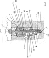
- FIG. 1 to 4 is an example of a possible embodiment of an electrohydraulic control valve according to the invention shown during Figure 5 represents an arrangement of two interconnected electrohydraulic control valves by way of example.
- FIG. 1 illustrated electrohydraulic control valve 1 in Catrigde design is shown in the open state. Regardless of the switching state of the control valve or directional control valve 1, an inflow 2 and an outflow 3 are provided in a housing block 4. Furthermore, an electrically controllable control piston 5 is provided, which can be moved axially in a housing bore 6. The total stroke is only about 3mm.
- a sleeve insert 7 is inserted into the housing bore 6, in which the control piston 5 is guided so as to be axially movable.
- the control piston 5 is designed with a valve cone 8 which can be controlled against a valve seat 9 formed in the sleeve insert 7. Accordingly, a gap for the fluid to flow through between the valve cone 8 and the valve seat 9 is realized by a corresponding axial movement of the control piston 5 from a closed state to an open state of the control piston 5.
- a control pin 10 for controlling the control piston 5 in an axial bore 11 of the control piston 5 is at least partially movable relative to the control piston 5, the spring-loaded control pin 10 having a Actuating drive 12 is in operative connection for axial movement.
- An electromagnet or the like, for example, can be provided as the actuating drive 12.
- the control pin 10 has a contact section 13 for axial contact with a corresponding contact section 14 of the control piston 5.
- the control pin 10 can initially be moved axially relative to the control piston 5 for control purposes until the contact section 13 of the control pin 5 rests against the corresponding contact section 14 of the control piston 5 in a sealing manner without play.
- This activation state with lowered control pin 10 is exemplified in FIG Figure 3 shown.
- the control pin 10 is then moved further axially together with the control piston 5 in order to achieve an open position of the control piston 5, which is exemplified in FIG Figure 4 is shown.
- the control pin 10 has an axially extending through hole 15 for pressure compensation or force compensation between the pressurized end regions of the control piston 5.
- the sleeve insert 7 inserted in the housing bore 6 is fixed to the housing and forms the valve seat 9 for the corresponding valve cone 8 of the control piston 5.
- the control piston 5 is axially movably guided in the sleeve insert 7, the sleeve insert 7 having a control edge 16 assigned to the inlet 2, which corresponds to a control web 18 of the control piston 5 having fine control grooves 17.
- a chamber 19 delimited on the one hand by the valve seat 9 corresponding to the valve cone 8 and on the other hand by the control edge 16 corresponding to the control web 18 is formed between the inner circumference of the sleeve insert 7 and the outer circumference of the control piston 5.
- An end of the control pin 10 facing away from the actuating drive 12 is in operative connection with a first return spring 20.
- a first return spring 20 An end of the control pin 10 facing away from the actuating drive 12 is in operative connection with a first return spring 20.
- the first return spring 20 of the control pin 10 is arranged in a spring cap 21 releasably fastened to one end of the control piston 5 and is axially supported.
- the assigned end of the control pin 10 can be in contact with the first return spring 20 directly or via a further component.
- a sleeve 22 is provided, which is partially surrounded by the first return spring 20 or is received in sections in the sleeve 22, the associated end of the first return spring 20 being supported on the sleeve 22, while the other end of the first Return spring 20 is supported in spring cap 21.
- a second return spring 23 is provided.
- the second return spring 23 is supported axially on the one hand on the spring cap 21 of the control piston 5 and on the other hand axially on the base 24 of the housing bore 6.
- the second return spring 23 surrounds the spring cap 21 in sections and is arranged coaxially to the spring cap 21.
- the spring cap 21 is assigned to the outlet 3 in the housing block 4 in such a way that a fluid flowing through the gap formed between the valve cone 8 and the valve seat 9 reaches the spring cap 21 can be guided to the drain 3 without turbulence. This prevents unwanted turbulence when flowing out into the drain 3.
- Figure 2 shows the closed state of the electrohydraulic control valve 1 or the control piston 5.
- the valve cone 8 of the control piston 5 rests on the corresponding valve seat 9 of the sleeve insert 7 in a fluid-tight manner due to the acting spring force of the second return spring 23, so that the outlet 3 opposite the chamber 19 is sealed.
- the chamber 19 is also sealed off from the inlet 2, since the control web 18 is located in overlap with the control edge 16 of the sleeve insert 7. This closed state is held by the spring force of the second return spring 23, not shown further.
- the contact section 13 of the control pin 10 is not in contact with the contact section 14 of the control piston 5, so that there is a predetermined axial play of about 0.2 mm between the contact section 13 of the control pin 10 and the contact section 14 of the control piston 5.
- FIG 3 A control state is shown in which the control pin 10 has been moved axially against the force of the first return spring 20, also not shown, relative to the control piston 5 by the actuating drive 12 in such a way that the contact section 13 of the control pin 10 seals against the contact section 14 of the control piston without play 5 is present.
- the electrohydraulic control valve is still in the closed state, since the inlet 2 as well as the chamber 19 and the outlet 3 are not fluidly connected in this state.
- FIG 4 is also in Figure 1
- the open state shown of the electrohydraulic control valve 1 or the control piston 5 is shown. Based on the actuation state, further actuation force is applied by the actuation drive 12 to the control pin 10, which is in operative connection with the control piston 5, so that the control pin 10 is moved further axially together with the control piston 5 and thus further down in the plane of the drawing. This opens the connection between the inflow 2 and the outflow 3, so that a fluid flow is generated through the control valve 1.
- This state is in Figure 4 shown, with the two return springs 20, 23 also being dispensed with in this illustration.
- control valve 1 or the control piston 5 is to be brought back into its closed state, the electrohydraulic control valve 1 shown in FIG Figure 3
- the control state shown is assumed in that the control piston 5 is moved back axially together with the control pin 10 until the control piston 5 rests in a fluid-tight manner on the valve seat 9 of the control valve 1. Since the control pin 10 rests on the control piston 5 without play in the actuation state, this advantageously prevents undesired impacts from occurring between the valve cone 8 and the valve 9, since the control pin 10 prevents further axial movement of the control piston 5.
- FIG. 5 an arrangement according to the invention with a first electrohydraulic control valve 1A and a second electrohydraulic control valve 1B in the housing block 4 is shown, as it were, as a double block.
- Identical components are denoted by the same reference numerals, the reference numerals of the first electrohydraulic control valve 1A being additionally provided with the letter A and the reference numerals of the second electrohydraulic control valve 1B being additionally provided with the letter B.
- the first electrohydraulic control valve 1A and the second electrohydraulic control valve 1B are arranged parallel to one another in the housing block 4 in a space-saving manner.
- An inflow 2A of the first electrohydraulic control valve 1A is connected to a pump (not shown further).
- An outflow 3A of the first electrohydraulic control valve 1A is connected to a consumer, also not shown.
- An inflow 2B of the second electrohydraulic control valve 1B is also connected to the consumer, for example via a common channel 25, the common channel 25 connecting the outflow 3A of the first electrohydraulic control valve 1A and the inflow 2B of the second electrohydraulic control valve 1B.
- An outflow 3B of the second electrohydraulic control valve 1B is connected to a tank (not shown further).
- the inventive method for opening and closing an electrohydraulic control valve 1 is in particular based on Figures 2 to 4 explained.
- the method provides for a control state when the control valve 1 is opened and closed in order to prevent undesired impacts between the valve cone 8 and the valve seat 9.
- the control pin 10 for opening the control valve 1 is initially moved axially relative to the control piston 5 until a control state is reached in which the contact section 13 of the control pin 10 rests against the contact section 14 of the control piston 5 without play and in a fluid-tight manner and that the control piston 5 is moved further axially via the control pin 10 for opening until the Control valve 1 is in the open state.
- control piston 5 To close the control piston 5 is axially moved back with the control pin 1 until the valve cone 8 is in fluid-tight contact with the valve seat 9 and the control pin 10 is then moved axially relative to the control piston 5 from the actuation state until a predetermined axial play between the contact section 13 of the Control pin 10 and the contact section 14 of the control piston 5 is given.
Landscapes
- Engineering & Computer Science (AREA)
- General Engineering & Computer Science (AREA)
- Mechanical Engineering (AREA)
- Fluid-Driven Valves (AREA)
Claims (11)
- Vanne de commande électrohydraulique (1) avec au moins une entrée (2) et une sortie (3) dans un bloc de boîtier (4) et avec un piston de commande (5) à pilotage électrique qui est guidé par déplacement axial dans un perçage de boîtier (6), le piston de commande (5) sollicitable par ressort étant pilotable avec un cône de vanne (8) contre un siège de vanne (9), au moins une tige de commande (10) pour le pilotage dans un perçage axial (11) du piston de commande (5) étant disposée de manière mobile au moins par section par rapport au piston de commande (5), la tige de commande (10) sollicitable par ressort étant en liaison fonctionnelle avec un mécanisme d'actionnement (12) pour le déplacement axial, et la tige de commande (10) présentant une section de contact (13) pour le contact axial au niveau d'une section de contact (14) concordante du piston de commande (5), la tige de commande (10) pour le pilotage par rapport au piston de commande (5) étant axialement déplaçable jusqu'à ce que la section de contact (13) de la tige de commande (10) soit en contact de manière étanche sans jeu au niveau de la section de contact (14) concordante du piston de commande (5), caractérisée en ce que
la tige de commande (10) est axialement déplaçable plus loin avec le piston de commande (5) afin d'atteindre un état ouvert du piston de commande (5) et en ce que la tige de commande (10) présente un perçage traversant (15) s'étendant axialement pour la compensation de la pression ou de la force entre les extrémités du piston de commande (5) soumises à la pression. - Vanne de commande électrohydraulique (1) selon la revendication 1, caractérisée en ce qu'une extrémité opposée au mécanisme d'actionnement (12) de la tige de commande (10) est en liaison fonctionnelle avec un premier ressort de rappel (20).
- Vanne de commande électrohydraulique (1) selon la revendication 2, caractérisée en ce que le premier ressort de rappel (20) de la tige de commande (10) est logée dans une calotte de ressort (21) fixée de manière détachable à une extrémité du piston de commande (5) et est supporté de manière axiale.
- Vanne de commande électrohydraulique (1) selon la revendication 3, caractérisée en ce qu'au moins un deuxième ressort de rappel (23) est prévu, le deuxième ressort de rappel (23) étant supporté axialement sur un côté au niveau de la calotte de ressort (21) du piston de commande (5) et axialement sur un autre côté au niveau du fond (24) du perçage de boîtier (6).
- Vanne électrohydraulique (1) selon la revendication 3 ou 4, caractérisée en ce que la calotte de ressort (21) est associée à la sortie (3) dans le bloc de boîtier (4) pour l'écoulement sans tourbillon d'un fluide s'écoulant à travers une fente formée entre le cône de vanne (8) et le siège de vanne (9) de sorte qu'un écoulement contournant les ressorts de rappel puisse être évité.
- Vanne électrohydraulique (1) selon l'une quelconque des revendications précédentes, caractérisée en ce qu'un élément de manchon (7) non mobile dans le boîtier et formant le siège de vanne (9) est disposé dans le perçage du boîtier (6), le piston de commande (5) étant guidé par déplacement axial dans ledit élément.
- Vanne électrohydraulique (1) selon la revendication 6, caractérisée en ce que l'élément de manchon (7) présente une arête de commande (16) associée à l'entrée (2) qui concorde avec une barrette de commande (18) du piston de commande (5) présentant des rainures de commande minces (17), et en ce qu'une chambre (19) limitée sur un côté par le siège de vanne (9) concordant avec le cône de vanne (8) et sur un autre côté par l'arête de commande (16) concordant avec la barrette de commande (18) est prévue.
- Dispositif avec au moins une première vanne de commande électrohydraulique (1A) et une deuxième vanne de commande électrohydraulique (1B) selon l'une quelconque des revendications précédentes.
- Dispositif selon la revendication 8, caractérisé en ce que la première vanne de commande électrohydraulique (1A) et la deuxième vanne de commande électrohydraulique (1B) sont disposées parallèlement l'une à côté de l'autre dans un bloc de boîtier (4), une entrée (2A) de la première vanne de commande électrohydraulique (1A) étant raccordable à une pompe et une sortie (3A) de la première vanne de commande électrohydraulique (1A) étant raccordable à un consommateur, et une entrée (2B) de la deuxième vanne de commande électrohydraulique (1B) étant raccordable au consommateur et une sortie (3B) de la deuxième vanne de commande électrohydraulique (1B) étant raccordable à un réservoir.
- Procédé pour ouvrir et fermer une vanne de commande électrohydraulique (1) selon l'une quelconque des revendications 1 à 7, caractérisé en ce que la tige de commande (10) est déplacée tout d'abord axialement par rapport au piston de commande (5) pour ouvrir la vanne de commande (1) jusqu'à ce qu'un état de pilotage soit atteint dans lequel la section de contact (13) de la tige de commande (10) est en contact sans jeu et de manière étanche aux fluides au niveau de la section de contact (14) du piston de commande (5) et en ce que le piston de commande (5) est déplacé axialement plus loin par la tige de commande (10) jusqu'à ce que la vanne de commande (1) se retrouve en l'état ouvert.
- Procédé selon la revendication 10, caractérisé en ce que pour la fermeture, le piston de commande (5) est reculé axialement avec la tige de commande (10) jusqu'à ce que le cône de vanne (8) soit en contact étanche aux fluides au niveau du siège de vanne (9) et en ce qu'ensuite, la tige de commande (10) est sortie de l'état de pilotage en continuant le déplacement axial par rapport au piston de commande (5) jusqu'à ce qu'un jeu axial prédéterminé existe entre la section de contact (13) de la tige de commande (10) et la section de contact (14) du piston de commande (5).
Priority Applications (1)
| Application Number | Priority Date | Filing Date | Title |
|---|---|---|---|
| EP20157531.3A EP3865746B1 (fr) | 2020-02-14 | 2020-02-14 | Soupape de commande électrohydraulique |
Applications Claiming Priority (1)
| Application Number | Priority Date | Filing Date | Title |
|---|---|---|---|
| EP20157531.3A EP3865746B1 (fr) | 2020-02-14 | 2020-02-14 | Soupape de commande électrohydraulique |
Publications (2)
| Publication Number | Publication Date |
|---|---|
| EP3865746A1 EP3865746A1 (fr) | 2021-08-18 |
| EP3865746B1 true EP3865746B1 (fr) | 2021-12-01 |
Family
ID=69630212
Family Applications (1)
| Application Number | Title | Priority Date | Filing Date |
|---|---|---|---|
| EP20157531.3A Active EP3865746B1 (fr) | 2020-02-14 | 2020-02-14 | Soupape de commande électrohydraulique |
Country Status (1)
| Country | Link |
|---|---|
| EP (1) | EP3865746B1 (fr) |
Families Citing this family (1)
| Publication number | Priority date | Publication date | Assignee | Title |
|---|---|---|---|---|
| DE102020119472B4 (de) * | 2020-07-23 | 2025-01-02 | Schaeffler Technologies AG & Co. KG | Vorgesteuertes Kühlmittelventil |
Family Cites Families (9)
| Publication number | Priority date | Publication date | Assignee | Title |
|---|---|---|---|---|
| US5188073A (en) * | 1990-04-06 | 1993-02-23 | Hitachi Ltd. | Fluid control valve, valve support member therefor and idling air amount control apparatus for automobile using the fluid control valve |
| FR2776045B3 (fr) * | 1998-03-13 | 2000-05-26 | Ind Mecanique Pour Les Fluides | Soupape a trois voies pour regulation de pression de fluide, en particulier de fluide sous haute pression |
| US6073652A (en) * | 1999-04-01 | 2000-06-13 | Husco International, Inc. | Pilot solenoid control valve with integral pressure sensing transducer |
| DE102005014418A1 (de) * | 2005-03-24 | 2006-09-28 | Werner Kosean | Hydraulisches Steuerventil |
| US20070157980A1 (en) * | 2006-01-11 | 2007-07-12 | Husco International, Inc. | Pilot operated control valve having a two stage poppet |
| DE102007010213B3 (de) * | 2007-02-28 | 2008-08-28 | Hydraulik-Ring Gmbh | Elektromagnetisches Regelventil und Verfahren zu dessen Steuerung |
| DE102013216568A1 (de) * | 2013-08-21 | 2015-02-26 | Continental Teves Ag & Co. Ohg | Elektromagnetventil, insbesondere für schlupfgeregelte Kraftfahrzeug-Bremsanlagen |
| DE102013217580B4 (de) * | 2013-09-04 | 2025-03-27 | Continental Automotive Technologies GmbH | Elektromagnetventil, insbesondere für schlupfgeregelte Kraftfahrzeug- Bremsanlagen |
| DE102016104135A1 (de) * | 2016-03-07 | 2017-09-07 | Svm Schultz Verwaltungs-Gmbh & Co. Kg | Ventilanordnung |
-
2020
- 2020-02-14 EP EP20157531.3A patent/EP3865746B1/fr active Active
Also Published As
| Publication number | Publication date |
|---|---|
| EP3865746A1 (fr) | 2021-08-18 |
Similar Documents
| Publication | Publication Date | Title |
|---|---|---|
| DE102009061003B4 (de) | Verstellbare Dämpfventileinrichtung | |
| DE102010063386B4 (de) | Verstellbare Dämpfventileinrichtung | |
| DE102010039917B4 (de) | Druckregelventil mit axialem Versorgungsanschluss | |
| DE3913460C2 (de) | Hydraulisches Umsteuerventil | |
| DE10037793B4 (de) | Magnetventil, insbesondere Druckregelventil | |
| DE102010039918A1 (de) | Druckregelventil in Schieberbauweise mit verbessertem Dämpfungsverhalten | |
| EP1180599A1 (fr) | Dispositif de sécurité pour une pompe pouvant être utilisée dans une transmission à fluide | |
| DE112007001455T5 (de) | Strömungsmittelgesteuertes Ventil | |
| EP3047183B1 (fr) | Dispositif de commande pour effectuer sélectivement une connexion fluidique et une déconnexion de points de raccordement fluidique | |
| DE102005042679A1 (de) | Bypassventil für Verbrennungskraftmaschinen | |
| WO2017125108A1 (fr) | Système de changement de vitesse hydraulique conçu pour un véhicule automobile | |
| EP2585745B1 (fr) | Vanne de commutation par pression des fluides | |
| DE102005018904B3 (de) | Thermostatventil für das Kühlsystem einer Verbrennungskraftmaschine | |
| DE102009042042B4 (de) | Multiplexventilanordnung | |
| EP3865746B1 (fr) | Soupape de commande électrohydraulique | |
| WO2023166073A1 (fr) | Vanne | |
| EP2436963A2 (fr) | Appareil de réglage pour la commande d'un flux de fluide | |
| DE4111064A1 (de) | Wegeventil mit zwei beabstandeten ventilkoerpern | |
| DE102017102842A1 (de) | Wellendurchführung sowie Ventil mit einer solchen Wellendurchführung und Verfahren zur Herstellung einer Wellendurchführung | |
| EP1801426B1 (fr) | Agencement de couplage hydraulique ou pneumatique | |
| EP2921925B1 (fr) | Soupape de réduction de pression | |
| EP4487053B1 (fr) | Soupape d'arrêt et système de réservoir d'hydrogène comprenant une soupape d'arrêt | |
| DE102019009464B4 (de) | Ventilkegel und Lasthalteventil mit Ventilkegel | |
| DE19750253C2 (de) | Lasthalteventilanordnung | |
| DE102005058625A1 (de) | Drehschieberventil |
Legal Events
| Date | Code | Title | Description |
|---|---|---|---|
| STAA | Information on the status of an ep patent application or granted ep patent |
Free format text: STATUS: EXAMINATION IS IN PROGRESS |
|
| PUAI | Public reference made under article 153(3) epc to a published international application that has entered the european phase |
Free format text: ORIGINAL CODE: 0009012 |
|
| 17P | Request for examination filed |
Effective date: 20201103 |
|
| AK | Designated contracting states |
Kind code of ref document: A1 Designated state(s): AL AT BE BG CH CY CZ DE DK EE ES FI FR GB GR HR HU IE IS IT LI LT LU LV MC MK MT NL NO PL PT RO RS SE SI SK SM TR |
|
| GRAP | Despatch of communication of intention to grant a patent |
Free format text: ORIGINAL CODE: EPIDOSNIGR1 |
|
| STAA | Information on the status of an ep patent application or granted ep patent |
Free format text: STATUS: GRANT OF PATENT IS INTENDED |
|
| RAP3 | Party data changed (applicant data changed or rights of an application transferred) |
Owner name: KOSEAN, WERNER |
|
| RIN1 | Information on inventor provided before grant (corrected) |
Inventor name: KOSEAN, WERNER |
|
| INTG | Intention to grant announced |
Effective date: 20210920 |
|
| GRAS | Grant fee paid |
Free format text: ORIGINAL CODE: EPIDOSNIGR3 |
|
| GRAA | (expected) grant |
Free format text: ORIGINAL CODE: 0009210 |
|
| STAA | Information on the status of an ep patent application or granted ep patent |
Free format text: STATUS: THE PATENT HAS BEEN GRANTED |
|
| AK | Designated contracting states |
Kind code of ref document: B1 Designated state(s): AL AT BE BG CH CY CZ DE DK EE ES FI FR GB GR HR HU IE IS IT LI LT LU LV MC MK MT NL NO PL PT RO RS SE SI SK SM TR |
|
| REG | Reference to a national code |
Ref country code: GB Ref legal event code: FG4D Free format text: NOT ENGLISH |
|
| REG | Reference to a national code |
Ref country code: AT Ref legal event code: REF Ref document number: 1452061 Country of ref document: AT Kind code of ref document: T Effective date: 20211215 Ref country code: CH Ref legal event code: EP |
|
| REG | Reference to a national code |
Ref country code: IE Ref legal event code: FG4D Free format text: LANGUAGE OF EP DOCUMENT: GERMAN |
|
| REG | Reference to a national code |
Ref country code: DE Ref legal event code: R096 Ref document number: 502020000386 Country of ref document: DE |
|
| REG | Reference to a national code |
Ref country code: LT Ref legal event code: MG9D |
|
| REG | Reference to a national code |
Ref country code: NL Ref legal event code: MP Effective date: 20211201 |
|
| PG25 | Lapsed in a contracting state [announced via postgrant information from national office to epo] |
Ref country code: RS Free format text: LAPSE BECAUSE OF FAILURE TO SUBMIT A TRANSLATION OF THE DESCRIPTION OR TO PAY THE FEE WITHIN THE PRESCRIBED TIME-LIMIT Effective date: 20211201 Ref country code: LT Free format text: LAPSE BECAUSE OF FAILURE TO SUBMIT A TRANSLATION OF THE DESCRIPTION OR TO PAY THE FEE WITHIN THE PRESCRIBED TIME-LIMIT Effective date: 20211201 Ref country code: FI Free format text: LAPSE BECAUSE OF FAILURE TO SUBMIT A TRANSLATION OF THE DESCRIPTION OR TO PAY THE FEE WITHIN THE PRESCRIBED TIME-LIMIT Effective date: 20211201 Ref country code: BG Free format text: LAPSE BECAUSE OF FAILURE TO SUBMIT A TRANSLATION OF THE DESCRIPTION OR TO PAY THE FEE WITHIN THE PRESCRIBED TIME-LIMIT Effective date: 20220301 |
|
| PG25 | Lapsed in a contracting state [announced via postgrant information from national office to epo] |
Ref country code: SE Free format text: LAPSE BECAUSE OF FAILURE TO SUBMIT A TRANSLATION OF THE DESCRIPTION OR TO PAY THE FEE WITHIN THE PRESCRIBED TIME-LIMIT Effective date: 20211201 Ref country code: PL Free format text: LAPSE BECAUSE OF FAILURE TO SUBMIT A TRANSLATION OF THE DESCRIPTION OR TO PAY THE FEE WITHIN THE PRESCRIBED TIME-LIMIT Effective date: 20211201 Ref country code: NO Free format text: LAPSE BECAUSE OF FAILURE TO SUBMIT A TRANSLATION OF THE DESCRIPTION OR TO PAY THE FEE WITHIN THE PRESCRIBED TIME-LIMIT Effective date: 20220301 Ref country code: LV Free format text: LAPSE BECAUSE OF FAILURE TO SUBMIT A TRANSLATION OF THE DESCRIPTION OR TO PAY THE FEE WITHIN THE PRESCRIBED TIME-LIMIT Effective date: 20211201 Ref country code: HR Free format text: LAPSE BECAUSE OF FAILURE TO SUBMIT A TRANSLATION OF THE DESCRIPTION OR TO PAY THE FEE WITHIN THE PRESCRIBED TIME-LIMIT Effective date: 20211201 Ref country code: GR Free format text: LAPSE BECAUSE OF FAILURE TO SUBMIT A TRANSLATION OF THE DESCRIPTION OR TO PAY THE FEE WITHIN THE PRESCRIBED TIME-LIMIT Effective date: 20220302 |
|
| PG25 | Lapsed in a contracting state [announced via postgrant information from national office to epo] |
Ref country code: NL Free format text: LAPSE BECAUSE OF FAILURE TO SUBMIT A TRANSLATION OF THE DESCRIPTION OR TO PAY THE FEE WITHIN THE PRESCRIBED TIME-LIMIT Effective date: 20211201 |
|
| PG25 | Lapsed in a contracting state [announced via postgrant information from national office to epo] |
Ref country code: SM Free format text: LAPSE BECAUSE OF FAILURE TO SUBMIT A TRANSLATION OF THE DESCRIPTION OR TO PAY THE FEE WITHIN THE PRESCRIBED TIME-LIMIT Effective date: 20211201 Ref country code: SK Free format text: LAPSE BECAUSE OF FAILURE TO SUBMIT A TRANSLATION OF THE DESCRIPTION OR TO PAY THE FEE WITHIN THE PRESCRIBED TIME-LIMIT Effective date: 20211201 Ref country code: RO Free format text: LAPSE BECAUSE OF FAILURE TO SUBMIT A TRANSLATION OF THE DESCRIPTION OR TO PAY THE FEE WITHIN THE PRESCRIBED TIME-LIMIT Effective date: 20211201 Ref country code: PT Free format text: LAPSE BECAUSE OF FAILURE TO SUBMIT A TRANSLATION OF THE DESCRIPTION OR TO PAY THE FEE WITHIN THE PRESCRIBED TIME-LIMIT Effective date: 20220401 Ref country code: ES Free format text: LAPSE BECAUSE OF FAILURE TO SUBMIT A TRANSLATION OF THE DESCRIPTION OR TO PAY THE FEE WITHIN THE PRESCRIBED TIME-LIMIT Effective date: 20211201 Ref country code: EE Free format text: LAPSE BECAUSE OF FAILURE TO SUBMIT A TRANSLATION OF THE DESCRIPTION OR TO PAY THE FEE WITHIN THE PRESCRIBED TIME-LIMIT Effective date: 20211201 Ref country code: CZ Free format text: LAPSE BECAUSE OF FAILURE TO SUBMIT A TRANSLATION OF THE DESCRIPTION OR TO PAY THE FEE WITHIN THE PRESCRIBED TIME-LIMIT Effective date: 20211201 |
|
| REG | Reference to a national code |
Ref country code: DE Ref legal event code: R097 Ref document number: 502020000386 Country of ref document: DE |
|
| PG25 | Lapsed in a contracting state [announced via postgrant information from national office to epo] |
Ref country code: MC Free format text: LAPSE BECAUSE OF FAILURE TO SUBMIT A TRANSLATION OF THE DESCRIPTION OR TO PAY THE FEE WITHIN THE PRESCRIBED TIME-LIMIT Effective date: 20211201 Ref country code: IS Free format text: LAPSE BECAUSE OF FAILURE TO SUBMIT A TRANSLATION OF THE DESCRIPTION OR TO PAY THE FEE WITHIN THE PRESCRIBED TIME-LIMIT Effective date: 20220401 |
|
| PLBE | No opposition filed within time limit |
Free format text: ORIGINAL CODE: 0009261 |
|
| STAA | Information on the status of an ep patent application or granted ep patent |
Free format text: STATUS: NO OPPOSITION FILED WITHIN TIME LIMIT |
|
| REG | Reference to a national code |
Ref country code: BE Ref legal event code: MM Effective date: 20220228 |
|
| PG25 | Lapsed in a contracting state [announced via postgrant information from national office to epo] |
Ref country code: LU Free format text: LAPSE BECAUSE OF NON-PAYMENT OF DUE FEES Effective date: 20220214 Ref country code: DK Free format text: LAPSE BECAUSE OF FAILURE TO SUBMIT A TRANSLATION OF THE DESCRIPTION OR TO PAY THE FEE WITHIN THE PRESCRIBED TIME-LIMIT Effective date: 20211201 Ref country code: AL Free format text: LAPSE BECAUSE OF FAILURE TO SUBMIT A TRANSLATION OF THE DESCRIPTION OR TO PAY THE FEE WITHIN THE PRESCRIBED TIME-LIMIT Effective date: 20211201 |
|
| 26N | No opposition filed |
Effective date: 20220902 |
|
| PG25 | Lapsed in a contracting state [announced via postgrant information from national office to epo] |
Ref country code: IE Free format text: LAPSE BECAUSE OF NON-PAYMENT OF DUE FEES Effective date: 20220214 |
|
| PG25 | Lapsed in a contracting state [announced via postgrant information from national office to epo] |
Ref country code: BE Free format text: LAPSE BECAUSE OF NON-PAYMENT OF DUE FEES Effective date: 20220228 |
|
| PG25 | Lapsed in a contracting state [announced via postgrant information from national office to epo] |
Ref country code: IT Free format text: LAPSE BECAUSE OF FAILURE TO SUBMIT A TRANSLATION OF THE DESCRIPTION OR TO PAY THE FEE WITHIN THE PRESCRIBED TIME-LIMIT Effective date: 20211201 |
|
| PG25 | Lapsed in a contracting state [announced via postgrant information from national office to epo] |
Ref country code: MK Free format text: LAPSE BECAUSE OF FAILURE TO SUBMIT A TRANSLATION OF THE DESCRIPTION OR TO PAY THE FEE WITHIN THE PRESCRIBED TIME-LIMIT Effective date: 20211201 Ref country code: CY Free format text: LAPSE BECAUSE OF FAILURE TO SUBMIT A TRANSLATION OF THE DESCRIPTION OR TO PAY THE FEE WITHIN THE PRESCRIBED TIME-LIMIT Effective date: 20211201 |
|
| PG25 | Lapsed in a contracting state [announced via postgrant information from national office to epo] |
Ref country code: HU Free format text: LAPSE BECAUSE OF FAILURE TO SUBMIT A TRANSLATION OF THE DESCRIPTION OR TO PAY THE FEE WITHIN THE PRESCRIBED TIME-LIMIT; INVALID AB INITIO Effective date: 20200214 |
|
| PG25 | Lapsed in a contracting state [announced via postgrant information from national office to epo] |
Ref country code: MT Free format text: LAPSE BECAUSE OF FAILURE TO SUBMIT A TRANSLATION OF THE DESCRIPTION OR TO PAY THE FEE WITHIN THE PRESCRIBED TIME-LIMIT Effective date: 20211201 |
|
| PG25 | Lapsed in a contracting state [announced via postgrant information from national office to epo] |
Ref country code: TR Free format text: LAPSE BECAUSE OF FAILURE TO SUBMIT A TRANSLATION OF THE DESCRIPTION OR TO PAY THE FEE WITHIN THE PRESCRIBED TIME-LIMIT Effective date: 20211201 |
|
| PG25 | Lapsed in a contracting state [announced via postgrant information from national office to epo] |
Ref country code: SI Free format text: LAPSE BECAUSE OF FAILURE TO SUBMIT A TRANSLATION OF THE DESCRIPTION OR TO PAY THE FEE WITHIN THE PRESCRIBED TIME-LIMIT Effective date: 20211201 |
|
| REG | Reference to a national code |
Ref country code: CH Ref legal event code: U11 Free format text: ST27 STATUS EVENT CODE: U-0-0-U10-U11 (AS PROVIDED BY THE NATIONAL OFFICE) Effective date: 20260301 |
|
| PGFP | Annual fee paid to national office [announced via postgrant information from national office to epo] |
Ref country code: GB Payment date: 20260115 Year of fee payment: 7 |
|
| PGFP | Annual fee paid to national office [announced via postgrant information from national office to epo] |
Ref country code: DE Payment date: 20260120 Year of fee payment: 7 |
|
| PGFP | Annual fee paid to national office [announced via postgrant information from national office to epo] |
Ref country code: AT Payment date: 20260121 Year of fee payment: 7 |
|
| PGFP | Annual fee paid to national office [announced via postgrant information from national office to epo] |
Ref country code: FR Payment date: 20260120 Year of fee payment: 7 |
|
| PGFP | Annual fee paid to national office [announced via postgrant information from national office to epo] |
Ref country code: CH Payment date: 20260301 Year of fee payment: 7 |