EP2437131B1 - Appareil de contrôle pour véhicule à fonctionnement autonome - Google Patents
Appareil de contrôle pour véhicule à fonctionnement autonome Download PDFInfo
- Publication number
- EP2437131B1 EP2437131B1 EP11182941.2A EP11182941A EP2437131B1 EP 2437131 B1 EP2437131 B1 EP 2437131B1 EP 11182941 A EP11182941 A EP 11182941A EP 2437131 B1 EP2437131 B1 EP 2437131B1
- Authority
- EP
- European Patent Office
- Prior art keywords
- travel
- vehicle
- output
- prescribed value
- sensor
- Prior art date
- Legal status (The legal status is an assumption and is not a legal conclusion. Google has not performed a legal analysis and makes no representation as to the accuracy of the status listed.)
- Not-in-force
Links
Images





Classifications
-
- G—PHYSICS
- G05—CONTROLLING; REGULATING
- G05D—SYSTEMS FOR CONTROLLING OR REGULATING NON-ELECTRIC VARIABLES
- G05D1/00—Control of position, course, altitude or attitude of land, water, air or space vehicles, e.g. using automatic pilots
- G05D1/02—Control of position or course in two dimensions
- G05D1/021—Control of position or course in two dimensions specially adapted to land vehicles
- G05D1/0259—Control of position or course in two dimensions specially adapted to land vehicles using magnetic or electromagnetic means
-
- G—PHYSICS
- G05—CONTROLLING; REGULATING
- G05D—SYSTEMS FOR CONTROLLING OR REGULATING NON-ELECTRIC VARIABLES
- G05D1/00—Control of position, course, altitude or attitude of land, water, air or space vehicles, e.g. using automatic pilots
- G05D1/02—Control of position or course in two dimensions
- G05D1/021—Control of position or course in two dimensions specially adapted to land vehicles
- G05D1/0259—Control of position or course in two dimensions specially adapted to land vehicles using magnetic or electromagnetic means
- G05D1/0265—Control of position or course in two dimensions specially adapted to land vehicles using magnetic or electromagnetic means using buried wires
-
- G—PHYSICS
- G05—CONTROLLING; REGULATING
- G05D—SYSTEMS FOR CONTROLLING OR REGULATING NON-ELECTRIC VARIABLES
- G05D1/00—Control of position, course, altitude or attitude of land, water, air or space vehicles, e.g. using automatic pilots
- G05D1/02—Control of position or course in two dimensions
- G05D1/021—Control of position or course in two dimensions specially adapted to land vehicles
- G05D1/0268—Control of position or course in two dimensions specially adapted to land vehicles using internal positioning means
- G05D1/027—Control of position or course in two dimensions specially adapted to land vehicles using internal positioning means comprising intertial navigation means, e.g. azimuth detector
-
- G—PHYSICS
- G05—CONTROLLING; REGULATING
- G05D—SYSTEMS FOR CONTROLLING OR REGULATING NON-ELECTRIC VARIABLES
- G05D1/00—Control of position, course, altitude or attitude of land, water, air or space vehicles, e.g. using automatic pilots
- G05D1/02—Control of position or course in two dimensions
- G05D1/021—Control of position or course in two dimensions specially adapted to land vehicles
- G05D1/0268—Control of position or course in two dimensions specially adapted to land vehicles using internal positioning means
- G05D1/0272—Control of position or course in two dimensions specially adapted to land vehicles using internal positioning means comprising means for registering the travel distance, e.g. revolutions of wheels
-
- G—PHYSICS
- G05—CONTROLLING; REGULATING
- G05D—SYSTEMS FOR CONTROLLING OR REGULATING NON-ELECTRIC VARIABLES
- G05D1/00—Control of position, course, altitude or attitude of land, water, air or space vehicles, e.g. using automatic pilots
- G05D1/02—Control of position or course in two dimensions
- G05D1/021—Control of position or course in two dimensions specially adapted to land vehicles
- G05D1/0268—Control of position or course in two dimensions specially adapted to land vehicles using internal positioning means
- G05D1/0274—Control of position or course in two dimensions specially adapted to land vehicles using internal positioning means using mapping information stored in a memory device
-
- G—PHYSICS
- G05—CONTROLLING; REGULATING
- G05D—SYSTEMS FOR CONTROLLING OR REGULATING NON-ELECTRIC VARIABLES
- G05D1/00—Control of position, course, altitude or attitude of land, water, air or space vehicles, e.g. using automatic pilots
- G05D1/02—Control of position or course in two dimensions
- G05D1/021—Control of position or course in two dimensions specially adapted to land vehicles
- G05D1/0212—Control of position or course in two dimensions specially adapted to land vehicles with means for defining a desired trajectory
- G05D1/0225—Control of position or course in two dimensions specially adapted to land vehicles with means for defining a desired trajectory involving docking at a fixed facility, e.g. base station or loading bay
-
- G—PHYSICS
- G05—CONTROLLING; REGULATING
- G05D—SYSTEMS FOR CONTROLLING OR REGULATING NON-ELECTRIC VARIABLES
- G05D1/00—Control of position, course, altitude or attitude of land, water, air or space vehicles, e.g. using automatic pilots
- G05D1/02—Control of position or course in two dimensions
- G05D1/021—Control of position or course in two dimensions specially adapted to land vehicles
- G05D1/0255—Control of position or course in two dimensions specially adapted to land vehicles using acoustic signals, e.g. ultra-sonic singals
Definitions
- US 2007 0 150 109 discloses a similar system, in which a wire is embedded on the border and a magnetic sensor detects the border.
- An odometer is also used to measure the distance travelled by the vehicle.
- Japanese Laid-Open Patent Application No. Hei 8(1996)-286738 discloses a technique to embed an electric wire along the border and detect generated magnetic field by a sensor mounted on an operating vehicle, thereby detecting the border. Further, Japanese Patent No. 3467136 ('136) proposes a technique to detect a position of an operating vehicle using GPS signals in addition to the foregoing magnetic induction techniques.
- the techniques in '812 and '738 enable to detect the border of the travel-scheduled area, it is preferable to additionally detect a position of the operating vehicle in the detected area for improving the work efficiency.
- the GPS signal is used in '136 to deal with it, it makes the structure complicated and may lead to the increase in cost, disadvantageously.
- An object of the invention is therefore to overcome the foregoing drawback by providing an apparatus for controlling an autonomous operating vehicle that can detect a position of the vehicle in an operating (travel-scheduled) area with the simple structure.
- the invention provides in the first aspect an apparatus for controlling an autonomous operating vehicle having a prime mover, a driven wheel connected to the prime mover, an operating machine, and a magnetic sensor adapted to produce an output indicative of magnetic field generated at an electric wire laid along a border of a travel-scheduled area, the vehicle being driven by the prime mover to autonomously travel in the travel-scheduled area defined by the border detected based on the output of the magnetic sensor, while performing operation using the operating machine, comprising: a geomagnetic sensor adapted to produce an output indicative of geomagnetism acting in the travel-scheduled area; an angular velocity sensor adapted to produce an output indicative of angular velocity generated about a vertical axis in center of gravity of the vehicle; a wheel speed sensor adapted to produce an output indicative of a speed of the driven wheel of the vehicle; a direction and distance calculator adapted to calculate a traveling direction based on the output of the angular velocity sensor and a traveled distance based on the output of the wheel speed sensor
- the invention provides in the second aspect an a method for controlling an autonomous operating vehicle having a prime mover, a driven wheel connected to the prime mover, an operating machine, and a magnetic sensor adapted to produce an output indicative of magnetic field generated at an electric wire laid along a border of a travel-scheduled area, the vehicle being driven by the prime mover to autonomously travel in the travel-scheduled area defined by the border detected based on the output of the magnetic sensor, while performing operation using the operating machine, comprising the steps of: obtaining a sensor output indicative of geomagnetism acting in the travel-scheduled area; obtaining a sensor output indicative of angular velocity generated about a vertical axis in center of gravity of the vehicle; obtaining a sensor output indicative of a speed of the driven wheel of the vehicle; calculating a traveling direction based on the sensor output indicative of the angular velocity and a traveled distance based on the sensor output of indicative of the wheel speed; driving the prime mover based on the calculated traveling direction so that the vehicle is
- FIG. 1 is an overall schematic view of a control apparatus for an autonomous operating vehicle according to an embodiment of the invention
- FIG. 2 is a block diagram showing input and output of sensors, an electronic control unit (ECU), electric motors (prime movers), etc., mounted on the vehicle
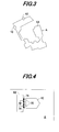
- FIG. 3 is a plan view showing a travel-scheduled area where the vehicle of FIG. 1 is to be traveled
- FIG. 4 is an explanatory view showing charging operation at a charge station (ST) shown in FIG. 1
- FIG. 5 is a block diagram showing the configuration of the charge ST shown in FIG. 4
- FIG. 6 is a block diagram showing the configuration of manipulation equipment used by an operator for the vehicle shown in FIG. 1
- FIG. 7 is a block diagram functionally showing the operation of the apparatus (ECU) shown in FIG. 2 .
- symbol 10 indicates an autonomous operating vehicle. As shown in FIGs. 1 and 2 , the vehicle 10 is installed with electric motors (prime movers) 12R, 12L for traveling.
- electric motors primary movers
- the motors 12R, 12L are connected to right and left driven wheels 14R, 14L (only the left side shown) attached on the rear side of a chassis 10a of the vehicle 10 and rotates the driven wheels 14R, 14L in the normal (forward traveling) direction or reverse (backward traveling) direction independently of each other.
- Right and left free wheels 16R, 16L are attached on the front side of the chassis 10a of the vehicle 10 through a stay 10b.
- Blades (rotary blades; operating machine) 20 for mowing lawn are attached in the center or thereabout of the chassis 10a.
- the blades 20 are connected to an electric motor 22 for operation to be rotated thereby, and also connected to a blade height adjustment mechanism 24 that can be manually operated by an operator (user).
- the blade height adjustment mechanism 24 is equipped with screws (not shown) to be manually turned by the operator for adjusting the height of the blades 20 from a contact ground GR.
- the chassis 10a is attached with a body frame 10c that covers the motors 12, 22, blades 20 and the like.
- a charging unit (including an AC/DC converter) 26 and a battery 30 are accommodated at the rear of the vehicle 10 and two charging terminals 32 (later shown in FIG. 4 ) are attached to the frame 10c to protrude backward.
- the terminals 32 are connected to the charging unit 26 and the charging unit 26 is connected to the battery 30 through wiring (not shown).
- the battery 30 is connected to the motors 12, 22 through wiring (not shown).
- the vehicle 10 comprises a four-wheel, unmanned, electric lawn-mower vehicle that is, for instance, about 500 millimeters long, 300 millimeters wide and 300 millimeters high and configured to travel within a travel-sheduled area (operating area) A shown in FIG. 3 .
- the front and rear ends of the vehicle 10 are attached with ultrasonic sensors 34F, 34R for detecting an obstacle and the frame 10c is attached with a contact sensor 36.
- the contact sensor 36 outputs an ON signal.
- An electronic control unit (ECU) 40 is installed in the center or thereabout of the vehicle 10, more specifically, on a printed-circuit board housed in an ECU housing box 40a.
- the ECU 40 includes a microcomputer having a CPU, ROM, RAM, I/Os, etc.
- An orientation sensor 42 is installed on the board in the ECU housing box 40a in the vicinity of the ECU 40 and generates an output or signal indicative of the primary reference direction on the earth, i.e., the north.
- the orientation sensor 42 comprises a triaxial geomagnetic sensor having outputs mx, my and mz in directions of three axes x, y and z.
- x indicates a traveling direction of the vehicle 10
- y a sideways direction perpendicular to the direction of x
- z a gravitational direction (direction penetrating the plane of paper) perpendicular to the directions of x and y .
- the board in the ECU housing box 40a is also installed near the orientation sensor 42 with a Yaw sensor (angular velocity sensor) 44 that (detects and) produces an output or signal indicative of angular velocity (yaw rate) generated about the z-axis in the center of gravity of the vehicle 10 and with a G sensor (acceleration sensor) 46 that (detects and) produces an output or signal indicative of the longitudinal (traveling) direction acceleration G acting on the vehicle 10.
- Yaw sensor angular velocity sensor
- G sensor acceleration sensor
- the upper surface of the frame 10c of the vehicle 10 is widely cut away and a display 54 is installed therein.
- the display 54 is connected to the ECU 40 to show an operation mode, etc., in response to a command sent from the ECU 40.
- a receiving antenna 40b is attached to the ECU housing box 40a and a radio 40c connected to the antenna 40b is installed in the ECU housing box 40a.
- the travel-scheduled area A shown in FIG. 3 has a shape as illustrated and a charge station (ST) 62 is arranged therein.
- An area wire (electric wire) 64 is laid (embedded) along a border of the travel-scheduled area A and operating area sensors 66F, 66R are installed at the front and rear of the vehicle 10, as shown in FIG. 1 .
- the operating area sensors 66 comprise magnetic sensors and produce outputs or signals indicative of magnetic field which is to be generated at the area wire 64 upon the supply of alternating current, as explained later.
- the outputs of the operating area sensors 66 are also sent to the ECU 40.
- the charge ST 62 is provided in the travel-scheduled area A so that, as shown in FIG. 4 , the vehicle 10 can be stopped and connected to the charge ST 62 through the charging terminals 32 to be charged thereby.
- the charge ST 62 is equipped with a charging device 74 connected to the commercial power source 70 through an electric outlet 72.
- the voltage of alternating current coming from the commercial power source 70 through the outlet 72 is appropriately stepped down by the AC/AC converter 74a and, when the vehicle 10 is connected to the charge ST 62 through the charging terminals 32 and 76, the alternating current is supplied to the vehicle 10 and stored in the battery 30 through the charging unit 26.
- Manipulation equipment to be used by the operator for manipulating the vehicle 10 includes a personal computer 80, a radio 82 connected thereto and a remote controller 84, as shown in FIG. 6 .
- the radio 82 and remote controller 84 have transmitting antennas 82a, 84a, respectively, so that they can send operation commands to the ECU 40 through the receiving antenna 40b and radio 40c in the vehicle 10.
- the ECU 40 is made connectable with an antitheft authentication device or the like.
- the ECU 40 has an direction and distance calculating section 40d that calculates a traveling direction in which the vehicle 10 travels based on the output of the Yaw sensor 44 and calculates a traveled distance of the vehicle 10 based on the output of the wheel speed sensor 50; a travel trajectory generating section 40e that drives the motors 12 through a motor driver 12a based on the calculated traveling direction so that the vehicle 10 is traveled around from a predetermined start point along the border of the travel-scheduled area A in accordance with the output of the operating area sensors (magnetic sensors) 66 and during the round travel, sequentially records the calculated traveling directions and traveled distances on a bitmap, defining the traveling (operation) area and comprising a plurality of divided bits, to generate a travel trajectory of the vehicle 10 with respect to the border of the travel-scheduled area A; a map information transforming section 40f that transforms the generated travel trajectory to map information; and a travel and operation (lawnmowing operation) controlling section 40g that determines a position
- FIG. 8 is a flowchart showing the foregoing operation of the ECU 40.
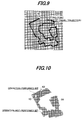
- the traveling direction and traveled distance calculated based on the outputs of the Yaw sensor 44 and wheel speed sensor 50 are sequentially plotted and recorded on the bitmap, comprising a plurality of divided bits, to generate the travel trajectory with respect to the border of the travel-scheduled area A, as shown in FIG. 9 .
- a unit area of each bit is set, for instance, to 300 millimeters x 300 millimeters based on the width of the operation performed through the blades 20.
- the unit area may be set through the manipulation equipment by the operator.
- the program proceeds to S20, in which in the traveling (operating) area A defined by the map information, it is determined for each bit whether the operation has been done, i.e., it is determined whether the position of the vehicle 10 is determined or detected using the bits; and the vehicle 10 is controlled to, as traveling straight as shown in FIG. 11 , perform the operation using the blades (operating machine) 20 based on the traveling direction and traveled distance (calculated by the direction and distance calculating section 40d) and the determined position (detected using the bits), utilizing the primary reference direction as a reference.
- the vehicle 10 is controlled to travel straight in the north-south directions in the travel-scheduled area A.
- the program proceeds to S22 and on, in which the sensor output is calibrated or corrected so that the travel trajectory can be newly generated. More precisely, when the distance exceeds the first prescribed value so that the result in S16 is negative, the program proceeds to S22, in which it is determined whether (an absolute value of) an azimuth angle difference between the end point at the time when the round travel is finished and the start point exceeds a second prescribed value.
- the program proceeds to S24, in which the output of the Yaw sensor 44 is calibrated.
- the calibration is made by correcting the center value of the Yaw sensor 44 outputs.
- the program proceeds to S28, in which based on the calibrated output of the Yaw sensor 44 or wheel speed sensor 50, the vehicle 10 is again traveled around and the travel trajectory is newly generated, whereafter the program returns to S16. Therefore, the travel trajectory is transformed to the map information only when the difference between the end point at the time when the round travel is finished and the start point does not exceed the first prescribed value.
- FIG. 12 is a flowchart showing the operation of the ECU 40 to be conducted concurrently with the straight travel control in S20 of the FIG. 8 flowchart.
- the outputs of the orientation sensor 42 are read. Then the program proceeds to S102, in which an average A of the sensor outputs is calculated and to S104, in which it is determined whether an absolute value of a difference between the average A and a value B is less than a third prescribed value, i.e., whether a change amount of the output of the orientation sensor 42 during the straight travel is less than the third prescribed value.
- the value B indicates an output of the orientation sensor 42 at the time when the vehicle 10 is started to travel around.
- the embodiment is configured to have an apparatus and method for controlling an autonomous operating vehicle (10) having a prime mover (electric motor 12), a driven wheel (14) connected to the prime mover, an operating machine (blades 20), and a magnetic sensor (operating area sensor 66) adapted to produce an output indicative of magnetic field generated at an electric wire (area wire 64) laid along a border of a travel-scheduled area (A), the vehicle being driven by the prime mover to autonomously travel in the travel-scheduled area defined by the border detected based on the output of the magnetic sensor, while performing operation using the operating machine, comprising: a geomagnetic sensor (orientation sensor 42) adapted to produce an output indicative of geomagnetism acting in the travel-scheduled area; an angular velocity sensor (Yaw sensor 44) adapted to produce an output indicative of angular velocity generated about a vertical axis in center of gravity of the vehicle; a wheel speed sensor (50) adapted to produce an output indicative of a speed of the driven wheel of the vehicle;
- the map information transformer determines whether a distance between an end point at time when the round travel is finished and the predetermined start point exceeds a first prescribed value (S16), and newly generates the travel trajectory when the distance is determined to exceed the first prescribed value (S28), while transforming the travel trajectory to the map information when the distance is determined not to exceed the first prescribed value (S 18). With this, it becomes possible to properly obtain the map information for the travel-scheduled area A and the accurate position of the vehicle 10 in the travel-scheduled area A can be detected, accordingly.
- the map information transformer determines whether an azimuth difference between the end point at the time when the round travel is finished and the predetermined start point exceeds a second prescribed value when the distance is determined to exceed the first prescribed value (S16, S22), and calibrates the output of the angular velocity sensor when the azimuth difference is determined to exceed the second prescribed value (S24).
- the map information transformer determines whether an azimuth angle difference between the end point at the time when the round travel is finished and the predetermined start point exceeds a second prescribed value when the distance is determined to exceed the first prescribed value (S16, S22), and calibrates the output of the wheel speed sensor when the azimuth angle difference is determined not to exceed the second prescribed value (S28).
- the travel and operation controller determines whether a change in the output of the geomagnetic sensor during the vehicle's straight travel is less than a third prescribed value (S100 to S104), and determines that the vehicle is traveled straight when the change is determined to be less than the third prescribed value (S106). With this, it becomes possible to further enhance the operation performance.
- a unit area of the bit of the bitmap is set based on width of the operation performed through the operating machine (blades 20). With this, it becomes possible to accurately detect the position of the vehicle 10 and achieve the further fine trace of the (lawnmowing) operation, thereby further enhancing the operation performance.
- the motor 12 is applied as the prime mover, it may be an internal combustion engine or another prime mover instead.
- the blades 20 for mowing lawn are exemplified as the operating machine, but it should not be limited thereto.
- an apparatus for controlling an autonomous operating vehicle having an operating machine and a magnetic sensor adapted to detect a border of a travel-scheduled area
- the vehicle is controlled to travel around the area from a start point along the border to sequentially record traveling directions and traveled distances on a bitmap (S10 to S 14).
- the generated travel trajectory is transformed to map information (S 18).
- a position of the vehicle is detected using bits of the bitmap of the transformed map information, and the vehicle is controlled to, as traveling straight in the north-south directions, while perform the operation with the operating machine based on the calculated traveling direction, the calculated traveled distance and the determined position, utilizing a primary reference direction obtained from a geomagnetic sensor as a reference (S20).
Landscapes
- Engineering & Computer Science (AREA)
- Physics & Mathematics (AREA)
- Radar, Positioning & Navigation (AREA)
- Remote Sensing (AREA)
- Aviation & Aerospace Engineering (AREA)
- General Physics & Mathematics (AREA)
- Automation & Control Theory (AREA)
- Electromagnetism (AREA)
- Control Of Position, Course, Altitude, Or Attitude Of Moving Bodies (AREA)
- Guiding Agricultural Machines (AREA)
- Navigation (AREA)
Claims (14)
- Appareil de contrôle d'un véhicule à fonctionnement autonome (10), comprenant un moteur principal (12), une roue entraînée (14) connectée au moteur principal, une machine de commande (20) et un capteur magnétique (66) adapté pour produire une sortie indicative d'un champ magnétique généré à un fil électrique (64) disposé le long d'une frontière d'une région de déplacement programmé (A), le véhicule étant entraîné par le moteur principal pour se déplacer de façon autonome dans la région de déplacement programmé définie par la frontière détectée sur la base de la sortie du capteur magnétique, tout en exécutant une opération en utilisant la machine de commande,
caractérisé en ce qu'il comprend:un capteur géomagnétique (42) adapté pour produire une sortie indicative d'un géomagnétisme qui agit dans la région de déplacement programmé;un capteur de vitesse angulaire (44) adapté pour produire une sortie indicative d'une vitesse angulaire générée autour d'un axe vertical dans le centre de gravité du véhicule;un capteur de vitesse de roue (50) adapté pour produire une sortie indicative d'une vitesse de la roue entraînée du véhicule;un calculateur de direction et de distance (40, 40d) adapté pour calculer une direction de déplacement sur la base de la sortie du capteur de vitesse angulaire et une distance parcourue sur la base de la sortie du capteur de vitesse de roue;un générateur de trajectoire de déplacement (40, 40e; S10 à S14) adapté pour entraîner le moteur principal sur la base de la direction de déplacement calculée de telle sorte que le véhicule se déplace à partir d'un point de départ prédéterminé (62) le long de la frontière de la région de déplacement programmé selon la sortie du capteur magnétique et pendant le déplacement rotatif du véhicule, afin d'enregistrer de façon séquentielle les directions de déplacement calculées et les distances parcourues calculées sur un topogramme binaire, définissant la région de déplacement programmé et comprenant une pluralité de bits divisés, afin de générer une trajectoire de déplacement par rapport à la frontière de la région de déplacement programmé;un transformateur d'informations de carte (40, 40f, S16, S18, S22 à S28) adapté pour transformer la trajectoire de déplacement générée en informations de carte composées, du topogramme binaire; etun dispositif de commande de déplacement et de fonctionnement (40, 40g, S20) adapté pour déterminer une position du véhicule en utilisant les bits du topogramme binaire des informations de carte transformées, et pour commander le véhicule, alors qu'il se déplace en ligne droite, pour exécuter l'opération en utilisant la machine de commande sur la base de la direction de déplacement calculée, de la distance parcourue calculée et de la position déterminée, en utilisant comme référence une direction de référence primaire obtenue à partir de la sortie du capteur géomagnétique. - Appareil selon la revendication 1, dans lequel le transformateur d'informations de carte détermine si une distance entre un point final au moment où le déplacement rotatif est terminé et le point de départ prédéterminé dépasse une première valeur prescrite (S16), et génère une nouvelle trajectoire de déplacement lorsqu'il est déterminé que la distance dépasse la première valeur prescrite (S28), tout en transformant la trajectoire de déplacement en informations de carte lorsqu'il est déterminé que la distance ne dépasse pas la première valeur prescrite (S18).
- Appareil selon la revendication 2, dans lequel le transformateur d'informations de carte détermine si une différence d'azimut entre le point final au moment où le déplacement rotatif est terminé et le point de départ prédéterminé dépasse une deuxième valeur prescrite lorsqu'il est déterminé que la distance dépasse la première valeur prescrite (S16, S22), et calibre la sortie du capteur de vitesse angulaire lorsqu'il est déterminé que la différence d'azimut dépasse la deuxième valeur prescrite (S24).
- Appareil selon la revendication 2 ou 3, dans lequel le transformateur d'informations de carte détermine si une différence d'angle d'azimut entre le point final au moment où le déplacement rotatif est terminé et le point de départ prédéterminé dépasse une deuxième valeur prescrite lorsqu'il est déterminé que la distance dépasse la première valeur prescrite (S16, S22), et calibre la sortie du capteur de vitesse de roue lorsqu'il est déterminé que la différence d'angle d'azimut ne dépasse pas la deuxième valeur prescrite (S28).
- Appareil selon l'une quelconque des revendications 1 à 4, dans lequel le dispositif de commande de déplacement et de fonctionnement détermine si un changement dans la sortie du capteur de géomagnétisme pendant le déplacement du véhicule en ligne droite est inférieur à une troisième valeur prescrite (S100 à S104), et détermine que le véhicule se déplace en ligne droite lorsqu'il est déterminé que le changement est inférieur à la troisième valeur prescrite (S106).
- Appareil selon la revendication 5, dans lequel le dispositif de commande de déplacement et de fonctionnement calibre la sortie du capteur de vitesse angulaire lorsqu'il est déterminé que le changement dépasse la troisième valeur prescrite (S108).
- Appareil selon l'une quelconque des revendications 1 à 6, dans lequel une surface unitaire du bit du topogramme binaire est déterminée sur la base de la largeur de l'opération exécutée par la machine de commande (20).
- Procédé de contrôle d'un véhicule à fonctionnement autonome (10) comprenant un moteur principal (12), une roue entraînée (14) connectée au moteur principal, une machine de commande (20) et un capteur magnétique (66) adapté pour produire une sortie indicative d'un champ magnétique généré à un fil électrique (64) disposé le long d'une frontière d'une région de déplacement programmé (A), le véhicule étant entraîné par le moteur principal pour se déplacer de façon autonome dans la région de déplacement programmé définie par la frontière détectée sur la base de la sortie du capteur magnétique, tout en exécutant une opération en utilisant la machine de commande,
caractérisé par les étapes consistant à:obtenir une sortie de capteur indicative du géomagnétisme qui agit dans la région de déplacement programmé;obtenir une sortie de capteur indicative d'une vitesse angulaire générée autour d'un axe vertical dans le centre de gravité du véhicule;obtenir une sortie de capteur indicative d'une vitesse de la roue entraînée du véhicule;calculer une direction de déplacement sur la base de la sortie du capteur de vitesse angulaire et une distance parcourue sur la base de la sortie du capteur de vitesse de roue (40, 40d);entraîner le moteur principal le moteur principal sur la base de la direction de déplacement calculée de telle sorte que le véhicule se déplace à partir d'un point de départ prédéterminé (62) le long de la frontière de la région de déplacement programmé selon la sortie du capteur magnétique et pendant le déplacement rotatif du véhicule, afin d'enregistrer de façon séquentielle les directions de déplacement calculées et les distances parcourues calculées sur un topogramme binaire, définissant la région de déplacement programmé et comprenant une pluralité de bits divisés, afin de générer une trajectoire de déplacement par rapport à la frontière de la région de déplacement programmé (40, 40e, S10 à S14);transformer la trajectoire de déplacement générée en informations de carte composées du topogramme binaire (40, 40f, S16, S18, S22 à S28); etdéterminer une position du véhicule en utilisant les bits du topogramme binaire des informations de carte transformées, et pour commander le véhicule, alors qu'il se déplace en ligne droite, pour exécuter l'opération en utilisant la machine de commande sur la base de la direction de déplacement calculée, de la distance parcourue calculée et de la position déterminée, en utilisant comme référence une direction de référence primaire obtenue à partir de la sortie du capteur géomagnétique (40, 40g, S20). - Procédé selon la revendication 8, dans lequel l'étape de transformation d'informations de carte détermine si une distance entre un point final au moment où le déplacement rotatif est terminé et le point de départ prédéterminé dépasse une première valeur prescrite (S16), et génère une nouvelle trajectoire de déplacement lorsqu'il est déterminé que la distance dépasse la première valeur prescrite (S28), tout en transformant la trajectoire de déplacement en informations de carte lorsqu'il est déterminé que la distance ne dépasse pas la première valeur prescrite (S18).
- Procédé selon la revendication 8, dans lequel l'étape de transformation d'informations de carte détermine si une différence d'azimut entre le point final au moment où le déplacement rotatif est terminé et le point de départ prédéterminé dépasse une deuxième valeur prescrite lorsqu'il est déterminé que la distance dépasse la première valeur prescrite (S16, S22), et calibre la sortie du capteur de vitesse angulaire lorsqu'il est déterminé que la différence d'azimut dépasse la deuxième valeur prescrite (S24).
- Procédé selon la revendication 8 ou 9, dans lequel l'étape de transformation d'informations de carte détermine si une différence d'angle d'azimut entre le point final au moment où le déplacement rotatif est terminé et le point de départ prédéterminé dépasse une deuxième valeur prescrite lorsqu'il est déterminé que la distance dépasse la première valeur prescrite (S16, S22), et calibre la sortie du capteur de vitesse de roue lorsqu'il est déterminé que la différence d'angle d'azimut ne dépasse pas la deuxième valeur prescrite (S28).
- Procédé selon l'une quelconque des revendications 8 à 11, dans lequel l'étape de commande de déplacement et de fonctionnement détermine si un changement dans la sortie du capteur de géomagnétisme pendant le déplacement du véhicule en ligne droite est inférieur à une troisième valeur prescrite (S100 à S104), et détermine que le véhicule se déplace en ligne droite lorsqu'il est déterminé que le changement est inférieur à la troisième valeur prescrite (S106).
- Procédé selon la revendication 12, dans lequel l'étape de commande de déplacement et de fonctionnement calibre la sortie du capteur de vitesse angulaire lorsqu'il est déterminé que le changement dépasse la troisième valeur prescrite (S108).
- Procédé selon l'une quelconque des revendications 8 à 13, dans lequel une surface unitaire du bit du topogramme binaire est déterminée sur la base de la largeur de l'opération exécutée par la machine de commande (20).
Applications Claiming Priority (1)
| Application Number | Priority Date | Filing Date | Title |
|---|---|---|---|
| JP2010222641A JP5420510B2 (ja) | 2010-09-30 | 2010-09-30 | 自律走行作業車の制御装置 |
Publications (2)
| Publication Number | Publication Date |
|---|---|
| EP2437131A1 EP2437131A1 (fr) | 2012-04-04 |
| EP2437131B1 true EP2437131B1 (fr) | 2013-08-21 |
Family
ID=44677746
Family Applications (1)
| Application Number | Title | Priority Date | Filing Date |
|---|---|---|---|
| EP11182941.2A Not-in-force EP2437131B1 (fr) | 2010-09-30 | 2011-09-27 | Appareil de contrôle pour véhicule à fonctionnement autonome |
Country Status (3)
| Country | Link |
|---|---|
| US (1) | US8744663B2 (fr) |
| EP (1) | EP2437131B1 (fr) |
| JP (1) | JP5420510B2 (fr) |
Families Citing this family (36)
| Publication number | Priority date | Publication date | Assignee | Title |
|---|---|---|---|---|
| US11835343B1 (en) * | 2004-08-06 | 2023-12-05 | AI Incorporated | Method for constructing a map while performing work |
| CA2806852C (fr) * | 2010-08-03 | 2018-09-04 | Fori Automation, Inc. | Systeme et procede de capteur a utiliser avec vehicule a guidage automatique (vga) |
| JP5420510B2 (ja) * | 2010-09-30 | 2014-02-19 | 本田技研工業株式会社 | 自律走行作業車の制御装置 |
| WO2014045859A1 (fr) * | 2012-09-18 | 2014-03-27 | 株式会社村田製作所 | Chariot à main |
| EP2939508B1 (fr) | 2012-12-28 | 2021-05-19 | Positec Power Tools (Suzhou) Co., Ltd | Système de tondeuse automatique |
| EP2972627B1 (fr) | 2013-03-15 | 2019-05-08 | MTD Products Inc | Système de travail mobile autonome comprenant une station de base à réflectivité variable |
| KR102079940B1 (ko) * | 2013-07-09 | 2020-02-21 | 삼성전자주식회사 | 마찰계수 추정 기능을 갖는 이동 로봇 및 마찰계수 추정 방법 |
| JP6214496B2 (ja) | 2014-08-27 | 2017-10-18 | 本田技研工業株式会社 | 自律走行作業車の制御装置 |
| JP2017535279A (ja) | 2014-09-23 | 2017-11-30 | 宝時得科技(中国)有限公司Positec Technology (China) Co.,Ltd. | 自動移動ロボット |
| JP6193898B2 (ja) * | 2015-02-10 | 2017-09-06 | 本田技研工業株式会社 | 自律走行作業車の制御装置 |
| JP5973608B1 (ja) * | 2015-03-27 | 2016-08-23 | 本田技研工業株式会社 | 無人作業車の制御装置 |
| JP6014192B1 (ja) * | 2015-03-27 | 2016-10-25 | 本田技研工業株式会社 | 無人作業車の制御装置 |
| WO2017051662A1 (fr) * | 2015-09-24 | 2017-03-30 | 日立工機株式会社 | Tondeuse à gazon autopropulsée |
| EP3156873B2 (fr) * | 2015-10-15 | 2023-04-05 | Honda Research Institute Europe GmbH | Véhicule autonome avec localisation simultanée améliorée et fonction de cartographie |
| KR101856503B1 (ko) * | 2016-04-29 | 2018-05-11 | 엘지전자 주식회사 | 이동 로봇 및 그 제어방법 |
| WO2017192981A1 (fr) | 2016-05-06 | 2017-11-09 | Mtd Products Inc | Système et procédé de navigation de tondeuse autonome |
| WO2018000922A1 (fr) | 2016-06-30 | 2018-01-04 | Tti (Macao Commercial Offshore) Limited | Tondeuse à gazon autonome et système de navigation associé |
| US11172608B2 (en) | 2016-06-30 | 2021-11-16 | Tti (Macao Commercial Offshore) Limited | Autonomous lawn mower and a system for navigating thereof |
| US10653057B2 (en) * | 2016-09-05 | 2020-05-19 | Lg Electronics Inc. | Moving robot and control method thereof |
| JP6956490B2 (ja) * | 2017-01-20 | 2021-11-02 | 株式会社クボタ | 分割マップ作成システム |
| WO2018158933A1 (fr) * | 2017-03-03 | 2018-09-07 | 本田技研工業株式会社 | Dispositif de commande d'affichage, procédé de commande d'affichage et support de stockage |
| EP3381257B1 (fr) * | 2017-03-28 | 2020-12-02 | Honda Research Institute Europe GmbH | Procédé pour générer une représentation d'une zone de travail d'une tondeuse à gazon autonome et système de tondeuse à gazon autonome |
| CN112020597A (zh) * | 2018-04-20 | 2020-12-01 | 山特维克矿山工程机械有限公司 | 控制移动采矿机移动的系统和方法 |
| KR102695152B1 (ko) * | 2018-10-25 | 2024-08-16 | 르노코리아 주식회사 | 자율주행 차량의 추측항법 성능 향상을 위한 직진 주행 판단 장치 및 그 방법 |
| CN111538321B (zh) * | 2019-01-22 | 2022-05-17 | 科沃斯机器人股份有限公司 | 自移动设备的控制方法、装置、设备及计算机可读存储介质 |
| DE202020101100U1 (de) | 2020-02-28 | 2020-03-13 | Stiga S.P.A. In Breve Anche St. S.P.A. | Rasenmäher mit elektronischer Steuereinheit |
| SE544298C2 (en) | 2020-04-14 | 2022-03-29 | Husqvarna Ab | Robotic work tool system and method for defining a working area |
| US12296694B2 (en) | 2021-03-10 | 2025-05-13 | Techtronic Cordless Gp | Lawnmowers |
| US12443180B2 (en) | 2021-11-10 | 2025-10-14 | Techtronic Cordless Gp | Robotic lawn mowers |
| AU2023200381A1 (en) | 2022-01-31 | 2023-08-17 | Techtronic Cordless Gp | Robotic garden tool |
| CN117008583A (zh) * | 2022-04-27 | 2023-11-07 | 南京泉峰科技有限公司 | 智能割草系统、自移动设备及设备定位校正方法 |
| EP4270138A1 (fr) | 2022-04-28 | 2023-11-01 | Techtronic Cordless GP | Création d'une limite virtuelle pour un outil de jardin robotisé |
| US12472611B2 (en) | 2022-05-31 | 2025-11-18 | Techtronic Cordless Gp | Peg driver |
| EP4310621B1 (fr) | 2022-07-19 | 2025-02-12 | Techtronic Cordless GP | Dispositif d'affichage pour commander un outil robotique |
| AU2023206123A1 (en) | 2022-07-29 | 2024-02-15 | Techtronic Cordless Gp | Generation of a cryptography key for a robotic garden tool |
| CN121075105A (zh) * | 2024-05-28 | 2025-12-05 | 北京高德云图科技有限公司 | 一种行驶状态检测方法、装置及设备 |
Family Cites Families (53)
| Publication number | Priority date | Publication date | Assignee | Title |
|---|---|---|---|---|
| JPS60183518A (ja) * | 1984-03-02 | 1985-09-19 | Nissan Motor Co Ltd | 操舵角検出装置 |
| JPS60239812A (ja) | 1984-05-14 | 1985-11-28 | Mitsubishi Electric Corp | 移動体の移動領域限定装置 |
| US4815008A (en) * | 1986-05-16 | 1989-03-21 | Denning Mobile Robotics, Inc. | Orientation adjustment system and robot using same |
| JP2572968B2 (ja) * | 1986-07-14 | 1997-01-16 | 株式会社椿本チエイン | 自律走行車の誘導方法 |
| DE3736386A1 (de) * | 1986-10-27 | 1988-07-14 | Pioneer Electronic Corp | Fahrzeugpeilverfahren |
| JP2667462B2 (ja) * | 1988-08-23 | 1997-10-27 | ヤンマー農機株式会社 | 農作業機における自動操舵制御装置 |
| JP2618041B2 (ja) * | 1988-10-13 | 1997-06-11 | 川崎重工業株式会社 | 無人走行装置 |
| JPH07119612B2 (ja) * | 1989-01-13 | 1995-12-20 | 日産自動車株式会社 | 車両用走行方位検出装置 |
| JP2785305B2 (ja) * | 1989-03-15 | 1998-08-13 | 松下電器産業株式会社 | 自走式掃除機 |
| JP2669889B2 (ja) * | 1989-04-07 | 1997-10-29 | 住友電気工業株式会社 | 自立航法装置に用いる角速度センサの較正装置 |
| JP2591192B2 (ja) * | 1989-11-02 | 1997-03-19 | 日産自動車株式会社 | 車両用走行方位検出装置 |
| US5187664A (en) * | 1990-11-27 | 1993-02-16 | Eaton-Kenway, Inc. | Proportional position-sensing system for an automatic guided vehicle |
| JPH04178587A (ja) * | 1990-11-13 | 1992-06-25 | Matsushita Electric Ind Co Ltd | 車両方位算出装置 |
| JP3018497B2 (ja) * | 1990-11-30 | 2000-03-13 | 住友電気工業株式会社 | 旋回角速度センサのオフセット補正装置 |
| JPH0739960B2 (ja) * | 1991-06-18 | 1995-05-01 | 住友電気工業株式会社 | 位置検出装置 |
| JP2961966B2 (ja) * | 1991-07-15 | 1999-10-12 | 松下電器産業株式会社 | 車両位置方位算出装置 |
| JPH0585206U (ja) * | 1991-07-18 | 1993-11-19 | 川崎重工業株式会社 | 自走式芝刈機 |
| JPH0585206A (ja) | 1991-09-25 | 1993-04-06 | Mazda Motor Corp | 車両のパワートレイン構造 |
| JPH0731062B2 (ja) * | 1992-02-10 | 1995-04-10 | 住友電気工業株式会社 | ジャイロのオフセット補正方法及び装置 |
| JPH0772926A (ja) * | 1993-09-03 | 1995-03-17 | Nissan Motor Co Ltd | 推測航法における推測位置修正方法 |
| US5528888A (en) * | 1993-12-27 | 1996-06-25 | Fuji Jukogyo Kabushiki Kaisha | Autonomous mowing vehicle and apparatus for detecting boundary of mowed field |
| JP3488969B2 (ja) * | 1994-03-09 | 2004-01-19 | 本田技研工業株式会社 | 車両誘導装置 |
| JP3632706B2 (ja) * | 1994-09-22 | 2005-03-23 | アイシン・エィ・ダブリュ株式会社 | 車両用ナビゲーション装置 |
| US5854987A (en) * | 1995-02-22 | 1998-12-29 | Honda Giken Kogyo Kabushiki Kaisha | Vehicle steering control system using navigation system |
| JPH08278817A (ja) * | 1995-04-05 | 1996-10-22 | Fuji Heavy Ind Ltd | 自律走行車の走行制御方法 |
| US5947225A (en) * | 1995-04-14 | 1999-09-07 | Minolta Co., Ltd. | Automatic vehicle |
| JPH08286738A (ja) | 1995-04-17 | 1996-11-01 | Kubota Corp | 移動車の誘導制御装置 |
| IL113913A (en) * | 1995-05-30 | 2000-02-29 | Friendly Machines Ltd | Navigation method and system |
| JP3467136B2 (ja) * | 1995-11-07 | 2003-11-17 | 富士重工業株式会社 | 自律走行車の走行制御装置 |
| US5764014A (en) * | 1996-02-01 | 1998-06-09 | Mannesmann Dematic Rapistan Corp. | Automated guided vehicle having ground track sensor |
| US6272406B2 (en) * | 1998-03-09 | 2001-08-07 | Jervis B. Webb Company | Guidance system for an automated guided-vehicle |
| IL124413A (en) | 1998-05-11 | 2001-05-20 | Friendly Robotics Ltd | System and method for area coverage with an autonomous robot |
| JP2000029521A (ja) * | 1998-07-08 | 2000-01-28 | Fuji Heavy Ind Ltd | 自律走行方法及び自律走行車 |
| JP2000029517A (ja) * | 1998-07-10 | 2000-01-28 | Fuji Heavy Ind Ltd | 自律走行車の走行制御装置 |
| US6256560B1 (en) * | 1999-02-25 | 2001-07-03 | Samsung Electronics Co., Ltd. | Method for correcting position of automated-guided vehicle and apparatus therefor |
| US6338013B1 (en) * | 1999-03-19 | 2002-01-08 | Bryan John Ruffner | Multifunctional mobile appliance |
| US6345217B1 (en) * | 2000-03-31 | 2002-02-05 | Rapistan Systems Advertising Corp. | Automated guided vehicle (AGV) with bipolar magnet sensing |
| US8396592B2 (en) * | 2001-06-12 | 2013-03-12 | Irobot Corporation | Method and system for multi-mode coverage for an autonomous robot |
| JP3926644B2 (ja) * | 2001-08-28 | 2007-06-06 | 理想科学工業株式会社 | 画像表示媒体及び画像表示装置 |
| JP3931680B2 (ja) * | 2002-02-18 | 2007-06-20 | 株式会社日本自動車部品総合研究所 | 車両の直進判別装置 |
| KR100461869B1 (ko) * | 2002-07-04 | 2004-12-14 | 삼성전자주식회사 | 무인반송 시스템의 제어방법 |
| DE10231386B4 (de) * | 2002-07-08 | 2004-05-06 | Alfred Kärcher Gmbh & Co. Kg | Sensorvorrichtung sowie selbstfahrendes Bodenreinigungsgerät mit einer Sensorvorrichtung |
| US6907336B2 (en) * | 2003-03-31 | 2005-06-14 | Deere & Company | Method and system for efficiently traversing an area with a work vehicle |
| JP2005103678A (ja) * | 2003-09-29 | 2005-04-21 | Toshiba Corp | ロボット装置 |
| KR100590549B1 (ko) * | 2004-03-12 | 2006-06-19 | 삼성전자주식회사 | 3차원 포인팅 방법을 이용한 로봇의 원격 제어 방법 및이를 구현한 로봇 제어 시스템 |
| JP4309384B2 (ja) * | 2005-08-31 | 2009-08-05 | 株式会社東芝 | ロボットシステム及びロボット管理装置 |
| JP2007117146A (ja) * | 2005-10-25 | 2007-05-17 | Matsushita Electric Ind Co Ltd | 自走式掃除機およびそのプログラム |
| US7991521B2 (en) * | 2006-02-01 | 2011-08-02 | Jervis B. Webb Company | Variable path automated guided vehicle |
| US7974738B2 (en) * | 2006-07-05 | 2011-07-05 | Battelle Energy Alliance, Llc | Robotics virtual rail system and method |
| JP2008027267A (ja) * | 2006-07-24 | 2008-02-07 | Matsushita Electric Ind Co Ltd | 自走式機器およびそのプログラム |
| US8224516B2 (en) * | 2009-12-17 | 2012-07-17 | Deere & Company | System and method for area coverage using sector decomposition |
| US8392044B2 (en) * | 2010-07-28 | 2013-03-05 | Deere & Company | Robotic mower boundary sensing system |
| JP5420510B2 (ja) * | 2010-09-30 | 2014-02-19 | 本田技研工業株式会社 | 自律走行作業車の制御装置 |
-
2010
- 2010-09-30 JP JP2010222641A patent/JP5420510B2/ja not_active Expired - Fee Related
-
2011
- 2011-09-22 US US13/240,684 patent/US8744663B2/en active Active
- 2011-09-27 EP EP11182941.2A patent/EP2437131B1/fr not_active Not-in-force
Also Published As
| Publication number | Publication date |
|---|---|
| JP2012079022A (ja) | 2012-04-19 |
| US8744663B2 (en) | 2014-06-03 |
| EP2437131A1 (fr) | 2012-04-04 |
| US20120083961A1 (en) | 2012-04-05 |
| JP5420510B2 (ja) | 2014-02-19 |
Similar Documents
| Publication | Publication Date | Title |
|---|---|---|
| EP2437131B1 (fr) | Appareil de contrôle pour véhicule à fonctionnement autonome | |
| EP2437132B1 (fr) | Appareil de contrôle pour véhicule à fonctionnement autonome | |
| EP2437130B1 (fr) | Appareil de contrôle pour véhicule à fonctionnement autonome | |
| EP3056960B1 (fr) | Appareil de commande de véhicule utilitaire à navigation autonome | |
| US8983693B2 (en) | Guidance apparatus of unmanned autonomous operating vehicle | |
| US10454287B2 (en) | Charging station for utility vehicle | |
| US9063547B2 (en) | Control apparatus of unmanned autonomous operating vehicle | |
| US9817398B2 (en) | Control apparatus for autonomously navigating utility vehicle | |
| US9876370B2 (en) | Charging station and charging station guide for autonomously navigating utility vehicle | |
| US9072218B2 (en) | Boundary sensor assembly for a robotic lawn mower, robotic lawn mower and robotic lawn mower system | |
| US9483053B2 (en) | Arrangement of area wire for unmanned autonomous operating vehicle and control apparatus of the same | |
| JP6243951B2 (ja) | 自律走行作業車の制御装置 | |
| US9026299B2 (en) | Navigation system and method for autonomous mower | |
| US12072711B2 (en) | Travel route control of autonomous work vehicle using global navigation satellite system | |
| US12510891B2 (en) | Travel route control of autonomous work vehicle to reduce travel distance | |
| US20230168687A1 (en) | Travel route control of autonomous work vehicle |
Legal Events
| Date | Code | Title | Description |
|---|---|---|---|
| PUAI | Public reference made under article 153(3) epc to a published international application that has entered the european phase |
Free format text: ORIGINAL CODE: 0009012 |
|
| 17P | Request for examination filed |
Effective date: 20110927 |
|
| AK | Designated contracting states |
Kind code of ref document: A1 Designated state(s): AL AT BE BG CH CY CZ DE DK EE ES FI FR GB GR HR HU IE IS IT LI LT LU LV MC MK MT NL NO PL PT RO RS SE SI SK SM TR |
|
| AX | Request for extension of the european patent |
Extension state: BA ME |
|
| RIC1 | Information provided on ipc code assigned before grant |
Ipc: G05D 1/02 20060101AFI20130116BHEP |
|
| GRAP | Despatch of communication of intention to grant a patent |
Free format text: ORIGINAL CODE: EPIDOSNIGR1 |
|
| GRAS | Grant fee paid |
Free format text: ORIGINAL CODE: EPIDOSNIGR3 |
|
| GRAA | (expected) grant |
Free format text: ORIGINAL CODE: 0009210 |
|
| AK | Designated contracting states |
Kind code of ref document: B1 Designated state(s): AL AT BE BG CH CY CZ DE DK EE ES FI FR GB GR HR HU IE IS IT LI LT LU LV MC MK MT NL NO PL PT RO RS SE SI SK SM TR |
|
| REG | Reference to a national code |
Ref country code: GB Ref legal event code: FG4D |
|
| REG | Reference to a national code |
Ref country code: CH Ref legal event code: EP |
|
| REG | Reference to a national code |
Ref country code: AT Ref legal event code: REF Ref document number: 628439 Country of ref document: AT Kind code of ref document: T Effective date: 20130915 |
|
| REG | Reference to a national code |
Ref country code: IE Ref legal event code: FG4D |
|
| REG | Reference to a national code |
Ref country code: DE Ref legal event code: R096 Ref document number: 602011002682 Country of ref document: DE Effective date: 20131010 |
|
| REG | Reference to a national code |
Ref country code: SE Ref legal event code: TRGR |
|
| REG | Reference to a national code |
Ref country code: AT Ref legal event code: MK05 Ref document number: 628439 Country of ref document: AT Kind code of ref document: T Effective date: 20130821 Ref country code: NL Ref legal event code: VDEP Effective date: 20130821 |
|
| REG | Reference to a national code |
Ref country code: LT Ref legal event code: MG4D |
|
| PG25 | Lapsed in a contracting state [announced via postgrant information from national office to epo] |
Ref country code: IS Free format text: LAPSE BECAUSE OF FAILURE TO SUBMIT A TRANSLATION OF THE DESCRIPTION OR TO PAY THE FEE WITHIN THE PRESCRIBED TIME-LIMIT Effective date: 20131221 Ref country code: LT Free format text: LAPSE BECAUSE OF FAILURE TO SUBMIT A TRANSLATION OF THE DESCRIPTION OR TO PAY THE FEE WITHIN THE PRESCRIBED TIME-LIMIT Effective date: 20130821 Ref country code: HR Free format text: LAPSE BECAUSE OF FAILURE TO SUBMIT A TRANSLATION OF THE DESCRIPTION OR TO PAY THE FEE WITHIN THE PRESCRIBED TIME-LIMIT Effective date: 20130821 Ref country code: CY Free format text: LAPSE BECAUSE OF FAILURE TO SUBMIT A TRANSLATION OF THE DESCRIPTION OR TO PAY THE FEE WITHIN THE PRESCRIBED TIME-LIMIT Effective date: 20130821 Ref country code: AT Free format text: LAPSE BECAUSE OF FAILURE TO SUBMIT A TRANSLATION OF THE DESCRIPTION OR TO PAY THE FEE WITHIN THE PRESCRIBED TIME-LIMIT Effective date: 20130821 Ref country code: PT Free format text: LAPSE BECAUSE OF FAILURE TO SUBMIT A TRANSLATION OF THE DESCRIPTION OR TO PAY THE FEE WITHIN THE PRESCRIBED TIME-LIMIT Effective date: 20131223 Ref country code: NO Free format text: LAPSE BECAUSE OF FAILURE TO SUBMIT A TRANSLATION OF THE DESCRIPTION OR TO PAY THE FEE WITHIN THE PRESCRIBED TIME-LIMIT Effective date: 20131121 |
|
| PG25 | Lapsed in a contracting state [announced via postgrant information from national office to epo] |
Ref country code: SI Free format text: LAPSE BECAUSE OF FAILURE TO SUBMIT A TRANSLATION OF THE DESCRIPTION OR TO PAY THE FEE WITHIN THE PRESCRIBED TIME-LIMIT Effective date: 20130821 Ref country code: FI Free format text: LAPSE BECAUSE OF FAILURE TO SUBMIT A TRANSLATION OF THE DESCRIPTION OR TO PAY THE FEE WITHIN THE PRESCRIBED TIME-LIMIT Effective date: 20130821 Ref country code: GR Free format text: LAPSE BECAUSE OF FAILURE TO SUBMIT A TRANSLATION OF THE DESCRIPTION OR TO PAY THE FEE WITHIN THE PRESCRIBED TIME-LIMIT Effective date: 20131122 Ref country code: LV Free format text: LAPSE BECAUSE OF FAILURE TO SUBMIT A TRANSLATION OF THE DESCRIPTION OR TO PAY THE FEE WITHIN THE PRESCRIBED TIME-LIMIT Effective date: 20130821 Ref country code: BE Free format text: LAPSE BECAUSE OF FAILURE TO SUBMIT A TRANSLATION OF THE DESCRIPTION OR TO PAY THE FEE WITHIN THE PRESCRIBED TIME-LIMIT Effective date: 20130821 Ref country code: PL Free format text: LAPSE BECAUSE OF FAILURE TO SUBMIT A TRANSLATION OF THE DESCRIPTION OR TO PAY THE FEE WITHIN THE PRESCRIBED TIME-LIMIT Effective date: 20130821 |
|
| PG25 | Lapsed in a contracting state [announced via postgrant information from national office to epo] |
Ref country code: RO Free format text: LAPSE BECAUSE OF FAILURE TO SUBMIT A TRANSLATION OF THE DESCRIPTION OR TO PAY THE FEE WITHIN THE PRESCRIBED TIME-LIMIT Effective date: 20130821 Ref country code: NL Free format text: LAPSE BECAUSE OF FAILURE TO SUBMIT A TRANSLATION OF THE DESCRIPTION OR TO PAY THE FEE WITHIN THE PRESCRIBED TIME-LIMIT Effective date: 20130821 Ref country code: EE Free format text: LAPSE BECAUSE OF FAILURE TO SUBMIT A TRANSLATION OF THE DESCRIPTION OR TO PAY THE FEE WITHIN THE PRESCRIBED TIME-LIMIT Effective date: 20130821 Ref country code: SK Free format text: LAPSE BECAUSE OF FAILURE TO SUBMIT A TRANSLATION OF THE DESCRIPTION OR TO PAY THE FEE WITHIN THE PRESCRIBED TIME-LIMIT Effective date: 20130821 Ref country code: CZ Free format text: LAPSE BECAUSE OF FAILURE TO SUBMIT A TRANSLATION OF THE DESCRIPTION OR TO PAY THE FEE WITHIN THE PRESCRIBED TIME-LIMIT Effective date: 20130821 Ref country code: DK Free format text: LAPSE BECAUSE OF FAILURE TO SUBMIT A TRANSLATION OF THE DESCRIPTION OR TO PAY THE FEE WITHIN THE PRESCRIBED TIME-LIMIT Effective date: 20130821 |
|
| PG25 | Lapsed in a contracting state [announced via postgrant information from national office to epo] |
Ref country code: MC Free format text: LAPSE BECAUSE OF FAILURE TO SUBMIT A TRANSLATION OF THE DESCRIPTION OR TO PAY THE FEE WITHIN THE PRESCRIBED TIME-LIMIT Effective date: 20130821 Ref country code: ES Free format text: LAPSE BECAUSE OF FAILURE TO SUBMIT A TRANSLATION OF THE DESCRIPTION OR TO PAY THE FEE WITHIN THE PRESCRIBED TIME-LIMIT Effective date: 20130821 |
|
| PLBE | No opposition filed within time limit |
Free format text: ORIGINAL CODE: 0009261 |
|
| STAA | Information on the status of an ep patent application or granted ep patent |
Free format text: STATUS: NO OPPOSITION FILED WITHIN TIME LIMIT |
|
| REG | Reference to a national code |
Ref country code: IE Ref legal event code: MM4A |
|
| 26N | No opposition filed |
Effective date: 20140522 |
|
| PG25 | Lapsed in a contracting state [announced via postgrant information from national office to epo] |
Ref country code: IE Free format text: LAPSE BECAUSE OF NON-PAYMENT OF DUE FEES Effective date: 20130927 |
|
| REG | Reference to a national code |
Ref country code: DE Ref legal event code: R097 Ref document number: 602011002682 Country of ref document: DE Effective date: 20140522 |
|
| REG | Reference to a national code |
Ref country code: CH Ref legal event code: PL |
|
| PG25 | Lapsed in a contracting state [announced via postgrant information from national office to epo] |
Ref country code: SM Free format text: LAPSE BECAUSE OF FAILURE TO SUBMIT A TRANSLATION OF THE DESCRIPTION OR TO PAY THE FEE WITHIN THE PRESCRIBED TIME-LIMIT Effective date: 20130821 |
|
| PG25 | Lapsed in a contracting state [announced via postgrant information from national office to epo] |
Ref country code: MT Free format text: LAPSE BECAUSE OF FAILURE TO SUBMIT A TRANSLATION OF THE DESCRIPTION OR TO PAY THE FEE WITHIN THE PRESCRIBED TIME-LIMIT Effective date: 20130821 Ref country code: TR Free format text: LAPSE BECAUSE OF FAILURE TO SUBMIT A TRANSLATION OF THE DESCRIPTION OR TO PAY THE FEE WITHIN THE PRESCRIBED TIME-LIMIT Effective date: 20130821 |
|
| PG25 | Lapsed in a contracting state [announced via postgrant information from national office to epo] |
Ref country code: RS Free format text: LAPSE BECAUSE OF FAILURE TO SUBMIT A TRANSLATION OF THE DESCRIPTION OR TO PAY THE FEE WITHIN THE PRESCRIBED TIME-LIMIT Effective date: 20131121 Ref country code: CH Free format text: LAPSE BECAUSE OF NON-PAYMENT OF DUE FEES Effective date: 20140930 Ref country code: MK Free format text: LAPSE BECAUSE OF FAILURE TO SUBMIT A TRANSLATION OF THE DESCRIPTION OR TO PAY THE FEE WITHIN THE PRESCRIBED TIME-LIMIT Effective date: 20130821 Ref country code: LU Free format text: LAPSE BECAUSE OF NON-PAYMENT OF DUE FEES Effective date: 20130927 Ref country code: LI Free format text: LAPSE BECAUSE OF NON-PAYMENT OF DUE FEES Effective date: 20140930 Ref country code: HU Free format text: LAPSE BECAUSE OF FAILURE TO SUBMIT A TRANSLATION OF THE DESCRIPTION OR TO PAY THE FEE WITHIN THE PRESCRIBED TIME-LIMIT; INVALID AB INITIO Effective date: 20110927 Ref country code: BG Free format text: LAPSE BECAUSE OF FAILURE TO SUBMIT A TRANSLATION OF THE DESCRIPTION OR TO PAY THE FEE WITHIN THE PRESCRIBED TIME-LIMIT Effective date: 20130821 |
|
| REG | Reference to a national code |
Ref country code: FR Ref legal event code: PLFP Year of fee payment: 6 |
|
| REG | Reference to a national code |
Ref country code: FR Ref legal event code: PLFP Year of fee payment: 7 |
|
| REG | Reference to a national code |
Ref country code: FR Ref legal event code: PLFP Year of fee payment: 8 |
|
| PG25 | Lapsed in a contracting state [announced via postgrant information from national office to epo] |
Ref country code: AL Free format text: LAPSE BECAUSE OF FAILURE TO SUBMIT A TRANSLATION OF THE DESCRIPTION OR TO PAY THE FEE WITHIN THE PRESCRIBED TIME-LIMIT Effective date: 20130821 |
|
| PGFP | Annual fee paid to national office [announced via postgrant information from national office to epo] |
Ref country code: SE Payment date: 20190910 Year of fee payment: 9 Ref country code: IT Payment date: 20190917 Year of fee payment: 9 |
|
| PGFP | Annual fee paid to national office [announced via postgrant information from national office to epo] |
Ref country code: GB Payment date: 20190926 Year of fee payment: 9 |
|
| GBPC | Gb: european patent ceased through non-payment of renewal fee |
Effective date: 20200927 |
|
| PG25 | Lapsed in a contracting state [announced via postgrant information from national office to epo] |
Ref country code: SE Free format text: LAPSE BECAUSE OF NON-PAYMENT OF DUE FEES Effective date: 20200928 Ref country code: GB Free format text: LAPSE BECAUSE OF NON-PAYMENT OF DUE FEES Effective date: 20200927 |
|
| REG | Reference to a national code |
Ref country code: SE Ref legal event code: EUG |
|
| PG25 | Lapsed in a contracting state [announced via postgrant information from national office to epo] |
Ref country code: IT Free format text: LAPSE BECAUSE OF NON-PAYMENT OF DUE FEES Effective date: 20200927 |
|
| REG | Reference to a national code |
Ref country code: DE Ref legal event code: R079 Ref document number: 602011002682 Country of ref document: DE Free format text: PREVIOUS MAIN CLASS: G05D0001020000 Ipc: G05D0001430000 |
|
| PGFP | Annual fee paid to national office [announced via postgrant information from national office to epo] |
Ref country code: FR Payment date: 20230808 Year of fee payment: 13 Ref country code: DE Payment date: 20230802 Year of fee payment: 13 |
|
| REG | Reference to a national code |
Ref country code: DE Ref legal event code: R119 Ref document number: 602011002682 Country of ref document: DE |
|
| PG25 | Lapsed in a contracting state [announced via postgrant information from national office to epo] |
Ref country code: DE Free format text: LAPSE BECAUSE OF NON-PAYMENT OF DUE FEES Effective date: 20250401 |
|
| PG25 | Lapsed in a contracting state [announced via postgrant information from national office to epo] |
Ref country code: FR Free format text: LAPSE BECAUSE OF NON-PAYMENT OF DUE FEES Effective date: 20240930 |