EP2437636B1 - Bett mit klapplehne - Google Patents
Bett mit klapplehne Download PDFInfo
- Publication number
- EP2437636B1 EP2437636B1 EP09776685.1A EP09776685A EP2437636B1 EP 2437636 B1 EP2437636 B1 EP 2437636B1 EP 09776685 A EP09776685 A EP 09776685A EP 2437636 B1 EP2437636 B1 EP 2437636B1
- Authority
- EP
- European Patent Office
- Prior art keywords
- lying
- head
- base part
- base
- axis
- Prior art date
- Legal status (The legal status is an assumption and is not a legal conclusion. Google has not performed a legal analysis and makes no representation as to the accuracy of the status listed.)
- Not-in-force
Links
- 238000010168 coupling process Methods 0.000 claims description 39
- 238000005859 coupling reaction Methods 0.000 claims description 39
- 230000008878 coupling Effects 0.000 claims description 38
- 238000006073 displacement reaction Methods 0.000 claims description 29
- 230000000903 blocking effect Effects 0.000 claims description 25
- 238000004146 energy storage Methods 0.000 claims description 3
- 238000009434 installation Methods 0.000 claims description 3
- 238000013461 design Methods 0.000 description 62
- 238000012546 transfer Methods 0.000 description 6
- 238000005096 rolling process Methods 0.000 description 5
- 230000013011 mating Effects 0.000 description 4
- 230000008901 benefit Effects 0.000 description 3
- 238000011161 development Methods 0.000 description 3
- 230000007246 mechanism Effects 0.000 description 3
- 230000007704 transition Effects 0.000 description 3
- 230000000712 assembly Effects 0.000 description 2
- 238000000429 assembly Methods 0.000 description 2
- 230000009849 deactivation Effects 0.000 description 2
- 230000000694 effects Effects 0.000 description 2
- 230000004044 response Effects 0.000 description 2
- 230000009286 beneficial effect Effects 0.000 description 1
- 230000005540 biological transmission Effects 0.000 description 1
- 239000002981 blocking agent Substances 0.000 description 1
- 230000008859 change Effects 0.000 description 1
- 238000005516 engineering process Methods 0.000 description 1
- 238000003780 insertion Methods 0.000 description 1
- 230000037431 insertion Effects 0.000 description 1
- 210000003127 knee Anatomy 0.000 description 1
- 210000002414 leg Anatomy 0.000 description 1
- 230000002093 peripheral effect Effects 0.000 description 1
- 238000005381 potential energy Methods 0.000 description 1
- 238000002360 preparation method Methods 0.000 description 1
- 238000004064 recycling Methods 0.000 description 1
- 230000000284 resting effect Effects 0.000 description 1
- 230000000630 rising effect Effects 0.000 description 1
- 230000006641 stabilisation Effects 0.000 description 1
- 238000011105 stabilization Methods 0.000 description 1
- 239000000758 substrate Substances 0.000 description 1
- 238000013519 translation Methods 0.000 description 1
Images



Classifications
-
- A—HUMAN NECESSITIES
- A47—FURNITURE; DOMESTIC ARTICLES OR APPLIANCES; COFFEE MILLS; SPICE MILLS; SUCTION CLEANERS IN GENERAL
- A47C—CHAIRS; SOFAS; BEDS
- A47C19/00—Bedsteads
- A47C19/02—Parts or details of bedsteads not fully covered in a single one of the following subgroups, e.g. bed rails, post rails
- A47C19/021—Bedstead frames
- A47C19/022—Head or foot boards
-
- A—HUMAN NECESSITIES
- A47—FURNITURE; DOMESTIC ARTICLES OR APPLIANCES; COFFEE MILLS; SPICE MILLS; SUCTION CLEANERS IN GENERAL
- A47C—CHAIRS; SOFAS; BEDS
- A47C20/00—Head-, foot- or like rests for beds, sofas or the like
- A47C20/04—Head-, foot- or like rests for beds, sofas or the like with adjustable inclination
-
- A—HUMAN NECESSITIES
- A47—FURNITURE; DOMESTIC ARTICLES OR APPLIANCES; COFFEE MILLS; SPICE MILLS; SUCTION CLEANERS IN GENERAL
- A47C—CHAIRS; SOFAS; BEDS
- A47C20/00—Head-, foot- or like rests for beds, sofas or the like
- A47C20/08—Head-, foot- or like rests for beds, sofas or the like with means for adjusting two or more rests simultaneously
Definitions
- the invention relates to a bed frame according to the preamble of claim 1.
- Generic bed frames are from the prior art, for example the DE 202006004074 U1 , known.
- the base part and the lying part are usually firmly connected to each other, so that even the mattress placed on such a bed frame is stationary to a substrate.
- the head part which usually extends vertically upwards at the head end, on the one hand serves aesthetic purposes and on the other hand makes it possible to assume a sitting position on the bed, in which the head part is used as a backrest.
- the head part itself forms no part of the receiving area for the mattress or mattress itself.
- a disadvantage of the known from the prior art bedsteads is considered that the sitting position, which is commonly used to read in bed with raised upper body, is not very convenient due to the vertical orientation of the head part. Although this can be improved by arranged between the headboard and the back cushion, an optimal reading position, however, often can not be achieved.
- the object of the invention is to provide a generic bed frame available, which eliminates the problem described above or at least reduced.
- a bed frame according to claim 1 achieved in which it is provided that the lying part relative to the base part along a Medeteilierispfad, which extends at least also in the bed longitudinal direction, is movably mounted and the head part about a bed transverse direction extended Kopfteilschwenkachse pivotally on the lying part or hinged to the base part.
- the bed top axis refers to a referenced on a flat surface in the vertical direction extending axis, the bed longitudinal axis an axis extending from the head of the bed frame to the foot end, and the bed transverse axis orthogonal to the bed top and bed longitudinal axis third axis space ,
- the bed frame according to the invention is characterized in that the lying part is movable relative to the base part along the lying part movement path.
- the lying part can therefore be displaced in the direction of the bed longitudinal axis relative to the base part.
- the base part is intended to be fixed in place and preferably has support area for this purpose, such as feet or the like.
- the lying part is arranged above the base part and has a receiving area which is intended to carry a mattress.
- the receiving area does not have to come into direct contact with the mattress. It can also be provided that the receiving area is intended to support a support surface or a slatted base for receiving the mattress.
- the recording area is large enough to accommodate a standard mattress of at least 180cm by 80cm or support circumferentially.
- the head part is preferably pivotably hinged to the head end of the lying part, so that a translational displacement of the lying part at the same time causes a translational displacement of the head part.
- the displaceability of the lying part relative to the base part is limited in the simplest case to a translational mobility in the direction of the bed longitudinal axis.
- a tilting mobility or a vertical mobility of the lying part is provided relative to the base part.
- the mobility of the lying part relative to the base part in the bed longitudinal direction is preferably at least 10 cm, in particular preferably at least 20 cm.
- the pivoting mobility of the head part is preferably at least 10 °, especially preferably at least 30 °.
- a rail guide is preferably provided.
- a guide rail system is understood to mean a guide system which, on the one hand, has a rolling body between the lying part and the base part and, on the other hand, prevents or at least severely restricts relative mobility between the base part and the lying part, at least in the transverse direction of the bed.
- the rolling elements can be attached to the base part or the lying part and roll on a counter surface on the other part.
- the side guide may be provided separately from the rolling bodies and the mating surface.
- the rolling bodies and the mating surface in such a way that they also directly effect the lateral guidance, for example by configuring the mating surface in the form of a groove in which the rolling bodies roll. It is particularly preferred if the mating surface is formed by a peripheral frame of the base part or of the lying part itself, since this makes it possible to dispense with a counter surface or rail separate therefrom.
- levers which are each rotatably mounted on the base parts on the one hand and on the lying part on the other hand, each having different pivot axes on the base part and on the lying part.
- the axes of rotation of these levers on the base part and the lying part are preferably aligned in the transverse direction of the bed.
- these levers allow a parallel displacement of the lying part relative to the base part, in which the lying part simultaneously displaced in the direction of the foot and in the direction of the bed high axis upward becomes. This can be beneficial as the shift upwards automatically leads to a restoring force that pushes the couch back down and towards the head end.
- the levers differ from one another with respect to the distance between the axis of rotation on the lying part and the axis of rotation on the base part, or that the distance of the base part-side axes of rotation on the one hand and the horizontal axis axes on the other hand differ from each other. In this way it can be achieved that a displacement of the lying part in the direction of the foot end simultaneously leads to a stronger lifting of the lying part at the foot end. This may be desirable to achieve a comfortable sitting and reading position on the bed.
- the lying part may be guided in the region of its head end by a rail guide on the base part, while at the foot of a lever is provided, which is articulated on the one hand on the lying part and on the other hand on the base part.
- the lying part in the area of the foot end is lifted in the direction of the foot end when it is displaced, whereas it does not undergo any vertical displacement in the area of the head end.
- the base part and the lying part are connected to one another via a coupling device, wherein this coupling device is designed such that the lying part or the receiving area of the lying part is forcibly raised or lowered at least partially when the lying part is displaced relative to the base part along the lying part movement path becomes.
- the relative position of the lying part to the base part and the relative position of the head part to the base part or lying part are operatively coupled to each other, so that pivoting of the head part from a basic position with a substantially vertically aligned front surface in a comfort position with swiveled front surface simultaneously with a Relocation of the lying part in the direction of the foot end is accompanied.
- the active coupling is preferably such that a pivoting of the head part by 20 ° causes a displacement of the lying part relative to the base part by at least 10cm in the direction of the bed longitudinal axis.
- the active coupling between the relative position of the lying part to the base part on the one hand and the head part to the base part or preferably to the lying part on the other hand can be achieved in various ways. It is considered to be particularly preferred if the relative position of the lying part to the base part on the one hand and the relative position of the head part to the base part and / or the lying part on the other hand are mechanically coupled to one another mechanically.
- a mechanical active coupling can be easily realized by machine elements such as gears, levers, chains, cables and the like.
- a mechanical active coupling also includes hydraulic or pneumatic solutions in which pistons are provided between the base part and the lying part on the one hand and between the head part and the lying part or the base part on the other hand.
- a variant of such a mechanical active coupling provides that the head part is pivotally mounted on the lying part about the head part pivot axis and a connection of the head part is provided to the base part without interposition of the lying part, by each position of the head part pivot axis along the Salispfades a pivotal position of the head part to the Headboard pivot axis is assigned.
- This connection of the head part to the base part does not have to be immediate, but can be done by a different from the lying part intermediate member.
- the connection of the head part to the base part leads to a limited mobility of the head part relative to the base part.
- This limited mobility of the head part relative to the base part in conjunction with the likewise limited mobility of the head part pivot axis along the lying part movement path, means that a pivoting of the head part caused by the user causes a translational displacement of the lying part relative to the base part.
- the lying part is thus directly coupled to the base part only via those components which serve for the mobility of the lying part relative to the base part, for example, the rail guide.
- the actual movement of the lying part relative to the base part is then effected by the head part, which in the course of pivoting also moves the head part pivot axis and thus the lying part lying thereon.
- connection of the head part to the base part is preferably designed such that the head part either on the one hand translationally along a headrest fixed or base part fixed sliding axis and on the other hand rotatably about an axis of rotation relative to the base part is movable or about a basisteilfeste axis of rotation on the one hand and about a fixedly spaced headboard fixed axis of rotation on the other hand is rotationally movable. Both designs allow the head part to be pivoted relative to the base part on the one hand and vertically displaced on the other hand.
- a design with a translational degree of freedom can, for example, be such that an intermediate element can be telescoped linearly relative to the base part and the head part is articulated to this intermediate element about a rotation axis fixed to the intermediate element.
- the sliding axis may also be provided fixed headboard, for example via a headrest fixed slot in which a fixed to the base bolt is movable.
- the last-mentioned design permits both the translational and the rotational mobility of the head part with only two components.
- a design with two axes of rotation can for example be designed such that an intermediate lever is articulated about a first axis of rotation on the base part and a second axis of rotation is articulated on the head part.
- a fundamentally different design in which a connection of the head part without interposition of the lying part to the base part does not necessarily have to be provided, provides that the head part is pivotally mounted on the lying part to the head part pivot axis and that a control member is provided which by one the headboard pivot axis non-parallel Steuerorgangraphachse rotatably mounted on a bearing part of the group comprising the lying part, the base part and the head part.
- the rotational position of the control member relative to the bearing part is coupled via a first active coupling with the pivotal position of the head part and operatively coupled via a second active coupling with the relative position of the lying part relative to the base part, wherein for this purpose a coupling member engages a movable along a movement path eccentric point of application of the control member through which the second active coupling is made with the lying part and / or the base part.
- the core of this design is said control element, which is mounted on the bearing part about an axis not parallel to the headstock pivot axis.
- a control member whose axis of rotation is parallel to the headstock pivot axis may also be expedient, however, since the control member for transmitting forces from the head portion to the base portion may be comparatively large due to large lever lengths required, an arrangement of the control member is rotational axis parallel to the headstock pivot axis both below the lying part as well as on the side facing away from the lying part of the head part difficult.
- an arrangement of the control member in the transverse direction of the bed next to the lying part is possible without problems.
- such a design is not always acceptable for aesthetic reasons.
- This problem is solved via the non-parallel axis of rotation of the control member to the headstock pivot axis.
- This orientation of the axis of rotation allows an arrangement of the control member, for example, under the lying part with substantially vertically aligned axis of rotation of the control member, said arrangement below the lying part does not diminish the aesthetic quality of the bed frame.
- the movement path extends in a fixed to the headboard plane extending in a fixed to the lying part extending plane, which is spanned by the bed transverse axis and the bed high axis, or in a fixed to the base part and / or Medeteil horizontally extending level runs.
- the usually approximately planar design of the head part is used here to accommodate the path of movement of the point of application.
- the movement path is in a plane that is aligned parallel to the front surface of the head part.
- the second variant provides that the path of movement of the point of application extends in a vertical plane and preferably at the head end of the bedstead. Here, too, there is sufficient space to accommodate the movement path, without this greatly impairing the creative freedom of the furniture designer.
- the third variant provides that the movement path runs in a horizontally extended plane. This level is preferably arranged below the lying part, ie also at a blind spot where there is sufficient space for the control element and the movement path and which does not constitute a restriction for the furniture designer under design aspects.
- the base part, the lying part and the headboard come into question.
- the base part or the lying part of the bearing part and the control member is rotatably mounted about a vertical axis or at least substantially vertical axis ( ⁇ 25 °, preferably ⁇ 15 °). This design is particularly useful when the path of movement of the point to be located below the lying part.
- An alternative embodiment provides that the lying part forms the bearing part and that the control member is rotatable about a horizontal axis of rotation extending in the bed longitudinal direction or at least substantially horizontal axis of rotation ( ⁇ 25 °, preferably ⁇ 15 °).
- the head part is the bearing part of the control member, in which case preferably the axis of rotation of the control member is aligned parallel to the front surface of the head part.
- a rigid thrust member is provided, which is articulated on the one hand eccentrically on the control member and on the other hand on the head part or lying part, depending on which of these parts does not form the bearing part of the control member.
- a pivoting of the head part relative to the lying part thus leads to a displacement of the articulation point of the thrust member and thus to a rotation of the control member.
- At least two rigid push elements are provided, wherein a first of these push elements is articulated eccentrically on the control member and a second of these push members on the head part and wherein the two push members coupled to each other via at least one rotatably mounted on one of the parts deflecting member are.
- This second variant is particularly useful when the control member is mounted about a preferably vertical axis of rotation, which is not provided in the region of the head end of the bed frame.
- the second thrust member can be used to transmit the pivotal movement of the head portion down to the level of the lying part or the base part, where by means of the pivotable deflecting the force is transmitted to the first thrust member, which is substantially horizontally below of the lying part or next to the lying part extends to the control member.
- a special variant is the third variant, in which fixedly on the control member, but eccentrically to the axis of rotation of the control member, a guide portion is provided which is forcibly guided by guide means in a head part or Medteil stationary guide plane, said guide plane is stationary to that part, which does not represent the bearing part.
- the coupling of the pivoting movement of the head part relative to the lying part in the control member takes place directly, since the forced operation of the guide portion of the control member in the management level for each pivotal position of the head part relative to the lying part only allows a defined rotational position of the control member relative to the bearing part.
- the guide portion is attached to a boom of the control member, which always extends in the movement of the head part approximately parallel to the guide plane. This makes it possible to accommodate this boom to the outside completely invisible in the lying part and the headboard.
- the guide means for guiding the guide portion of the control member in the guide plane may comprise, in a first embodiment, two opposing guide surfaces which are arranged on opposite sides of the guide portion of the control member. Depending on the pivoting direction of the head part relative to the lying part of the guide section is then on each one of these guide surfaces forced out.
- An alternative design for this purpose provides that a guide lever is provided, which is pivotably articulated on the guide portion and which is also pivotally mounted about a guide to the plane orthogonal guide lever axis. Since this guide lever is movable only parallel to the guide plane, it also forces the guide section to a circular segment-shaped movement parallel to the guide plane.
- a first preferred variant provides that a slide guide is provided with a sliding recess and a sliding block slide, by which the control member is connected to the base part or the lying part. During a rotational movement of the control member of the slotted guide is displaced in the sliding recess and thereby causes a relative displacement of the lying part relative to the base part.
- the sliding recess can be provided on the one hand on the lying part or on the base part and on the other hand also on the control member itself.
- the slide is mounted on the other part.
- a second variant with respect to this second active coupling provides that a thrust member is used which is articulated on the one hand at the point of application of the control member and which on the other hand is articulated on the base part or on the lying part.
- a thrust member is used which is articulated on the one hand at the point of application of the control member and which on the other hand is articulated on the base part or on the lying part.
- Such a design with a rigid push member is very easy to implement.
- three-dimensionally acting joints such as ball joints are expedient, since the point of engagement on the control member in this case also displaced vertically during a rotational movement of the control member.
- a third preferred variant provides that a flexible strand is used, which is attached to the point of application of the control member and which is guided by a strand guide on the base part or on the lying part to a mounting on the other of the two parts.
- a strand can be configured as a strand which can be loaded purely on tension or else as a strand designed to absorb tensile and compressive forces.
- a design with two strands which can only be loaded on a train and which transmit the forces as a function of the direction of movement of the head part is also included.
- the strand guide can be formed, for example, by simple deflection rollers or by a strand sleeve extending along the strand in which the strand is guided.
- the design with a flexible strand as a Wirkkopplungsglied is especially advantageous if the path of movement of the point in a fixed to the headboard level is because a strand in a simple manner, the transfer of forces from the headboard in the lying part and the base part is possible ,
- a manually activatable and / or deactivatable blocking means is provided by which the relative mobility of the head part, the lying part and / or the base part can be blocked to each other, wherein the blocking means preferably directly blocking the relative mobility between the base part and the lying part and indirectly blocks the relative mobility of the head part relative to the base part or the lying part.
- the blocking means is designed such that it remains in a blocking state without manual intervention and must be manually deactivated in order to change the pivoting position of the head part relative to the lying part.
- the blocking agent is designed bistable and in a once produced Blocking and a non-blocking state each remains until it is manually transferred to the other state.
- the blocking means may also be designed so that it acts only in one direction of movement and thus prevents, for example, only the return to the basic position of the bed frame in the activated state.
- the design of the blocking means for directly blocking the mobility of the lying part relative to the base part is advantageous because this relative mobility compared to the relative mobility of the head part relative to the lying part is comparatively large, so that the forces occurring, against which the blocking must act, are relatively small.
- Also advantageous is a design in which the required pivoting moment is increased at the head part for effective coupling of the bed part when pivoting from the basic position to the comfort position initially over a range between 0.5 ° to 3 ° size compared to the subsequently required pivoting moment, so that an unintentional pivoting of the head part is prevented.
- At least one Kraftbeetzleyungsmittel with energy storage preferably a spring means is provided by which the lying part is subjected to force in the direction of an end position in the direction of the head end relative to the base part and / or the head part in the direction of a position in which the front surface aligned vertically is, is being charged.
- Such Kraftbeetzschlagungsmittel with energy storage serves the purpose of acting through during the transfer of the bed frame in the comfort position absorbed energy in the direction of the basic position of the bed frame.
- An embodiment of this comprises a weight which is raised and its potential energy for recycling the bed frame in the basic position is used.
- the design is preferred with a spring means, against the spring force, the pivoting of the head part takes place in the direction of the comfort position. As soon as the force introduced by the user into the system is eliminated and any blocking means which may be present is deactivated, the bed frame thus returns to the basic position.
- a bedside table surface is provided on the bed frame, which is fixedly attached to the lying part.
- a storage area preferably at least 20cm x 20cm, especially preferably at least 30cm x 30cm is considered, which is offset from the lying part, but is fixedly connected thereto.
- the advantage of the fixed connection to the lying part results from the fact that in a displacement of the lying part in the direction of the foot and the bedside table is mitverlagert.
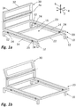
- Fig. 1a and 1b show a particularly simple design of a bed frame. This has a base part 10, a lying part 20 and a head part 30. This example only serves to clarify the basic structure and is not covered by the invention for lack of the inventively provided active coupling.
- the base part 10 is used for stationary installation and has feet 12 for this purpose. Between each two feet 12 on the same longitudinal side of the bed frame in each case one longitudinally extending in bed longitudinal direction 2 longitudinal member 14 is provided, wherein the two side rails 14 are connected to each other by a cross member 16.
- the lying part 20 is provided, which has a horizontally extending circumferential frame 22 which forms a receiving area 23 for a slatted frame and a mattress to be placed thereon.
- a total of four rollers 24 are provided, which are rotatably mounted about the transverse axis of the bed 4 parallel axes of rotation. These rollers 24 are placed on the longitudinal members 14 of the base member 10 and thereby allow a displacement of the lying part 20 together with the below-described head part 30 in the direction of the bed longitudinal axis 2.
- About guide plates 25 which are provided in the region of each roller 24 is a Guaranteed lateral guidance, so that the lying part 20 can not slip in the direction of the transverse bed axis 4 from the base part 10.
- the head part 30 is pivoted at the head end of the lying part 20 about a parallel to the bed transverse axis 4 head part pivot axis 4a. It can thereby from the vertical basic position, which in Fig. 1a is shown, are pivoted to the rear.
- the head part pivot axis 4a is preferably arranged between 15 cm and 50 cm above the receiving area 23, in order to achieve that, with a corresponding mattress thickness, the head part pivot axis 4a is arranged approximately at the level of the upper side of the mattress.
- Fig. 1b shows the bedstead the Fig. 1a after transfer to the comfort position.
- the lying part 20 is displaced relative to the base part 10 in the direction of the foot end. This displacement allows the head part 30 to pivot backwards can, without the headboard protrudes significantly in the bed longitudinal direction 2 on the base member 10.
- the comfort position of Fig. 1b is intended to provide a user with a comfortable sitting and reading position in bed.
- the user can comfortably sit on the mattress not shown his back against the tilted into the comfort position headboard and so take a reading position that is similar to the sitting position on a chair.
- a padded surface in addition to a slatted frame for accommodating the mattress, is also preferably attached to the head part 30, which covers the front surface 34 defined by the frame 32 of the head part 30.
- adjusting means and / or locking means for influencing and fixing the respective position of the lying part 20 relative to the base part 10 and the head part 30 relative to the lying part 20.
- such means are provided to adjust the relative position and to fix a once established setting.
- Fig. 1a and 1b While in the embodiment of the Fig. 1a and 1b a separate adjustment of the relative position of the lying part 20 relative to the base part 10 and the head part 30 relative to the lying part 20 is required, the invention provides that the respective relative positions are coupled together so that each tilt angle of the head part associated with a relative position of the lying part relative to the base part is.
- Fig. 2 to 13 Is that the case.
- These embodiments each have one with the Embodiment of Fig. 1a and 1b matching basic structure, which is no longer explained individually.
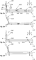
- a rigid push rod 140 is provided, which is also articulated eccentrically on a control member 150, which in turn is rotatably mounted about a 4 parallel to the transverse bed axis Steuerorganfanachse 4b.
- a pivoting of the head part 130 relative to the lying part 120 thereby also to a pivoting of the control member 150 relative to the lying part 120.
- the control member 150 additionally has a sliding recess 152 in the form of a slot into which a bolt 142 attached to the base protrudes as a sliding block ,
- the described active coupling via the control member 150 thus leads to a user achieved by reclining by pivoting the head portion 130 automatically causes a displacement of the lying part 120 in the direction of the foot end.
- the components 150, 140, 142 required for this purpose are arranged laterally next to the lying part 120.
- This solution leads to the problem that the mechanism is arranged on the side of the lying part 120 and therefore must be hidden and thus limits the freedom of design of the furniture designer becomes.
- the below explained embodiments of the Fig. 4 to 10 solve this by a three-dimensional mechanics.
- a blocking device 160 which has a blocking block made of rubber 162 which is articulated movably on the lying part 120 and is permanently subjected to force by means of a spiral spring 164 in the direction of the base part 110. Without manual intervention on the blocking device thus the blocked state of Fig. 2b a, by which a relative displacement of the lying part 120 relative to the base part 110 is prevented. Deactivation of this blocking device 160 is manually possible via a lever 166 provided for this purpose, as in FIG Fig. 2a is shown. This manual deactivation is done as intended, before the user of the bed frame transferred by applying force to the head portion 130 in the comfort position. After reaching the comfort position of Fig.
- the second noteworthy further subassembly is the spring device 170.
- This comprises a helical tension spring 172, which is fastened on the one hand to the lying part 120 and on the other hand to the base part 110. As the Fig. 2b shows, this spring 172 is stretched when the bed frame is transferred in its comfort position. As a result, a restoring force is established, which is a return transfer from the comfort position of Fig. 2b into the basic position of Fig. 2a alone by releasing the blocking device 160 permits.
- assemblies 160 and 170 are not shown in the other embodiments of the invention. However, they are also provided in the other embodiments.
- the active coupling to the pivoting position of the head part 230 is in a similar manner as in the embodiment of Fig. 2a and 2b realized by a rod 242 or otherwise on train resilient connection part on the one hand on the head part 230 and on the other hand eccentrically to the rotation axis 4f is hinged to the head part side lever 250.
- the lever 250 is erected by pivoting the head part 230 to the rear, which is accompanied by the above-described displacement of the lying part 220 relative to the base part 210.
- a first variant, not shown, for the design of the Fig. 3a and 3b provides that the distance between the pivot axes 4c and 4d to each other is greater than the distance between the pivot axes 4e and 4f to each other. This has the effect that, when the bed frame is transferred to the comfort position, the foot end of the lying part is lifted to a greater extent than the head end. This makes it possible to realize a particularly advantageous comfort position in which the legs of the user lie in a slightly rising position on the mattress.
- a push rod 340 In the design of Fig. 4a and 4b is similar to the design of the Fig. 2a and 2b attached to the head portion 330, a push rod 340. However, this does not act directly on the largely disposed below the lying part control member 350, but first on a parallel to the bed transverse axis 4 axis 4g mounted deflecting 342. At this a second push rod 344 is also spaced articulated to the pivot axis 4g of the deflecting member 342, which is extends approximately in the direction of the bed longitudinal axis 2 and the opposite end is connected to the aforementioned control member 350.
- the control member 350 is designed as a pivoting lever, which is mounted on a lying parallel to the bed high axis 6 Steuerorganfanachse 6 a pivotally mounted on the lying part 320.
- the pivot point 352 for the second push rod 344 is provided very close to the pivot axis 6a.
- a sliding recess 354 Much further from the pivot axis 6a spaced and thus causing a large translation is provided on the control member a sliding recess 354, in which a basisteilfester bolt 346 protrudes as gate slider.
- FIG. 4a and 4b An unrepresented variant of the design of Fig. 4a and 4b provides that the sliding recess is provided on the cross member 316 fixed to the base part 310 and that the sliding block slide instead of the base member 310 is fixedly mounted on the control member 350.
- the design according to the Fig. 5a and 5b has a control member 450, which is mounted in the region of the head end by means of a main portion 450a on the lying part about a rotation axis 6b. Similar to the embodiment of Fig. 4a and 4b a lever portion 450b is also provided on this control member, which causes a rotary movement of the control member 450 in a translational movement of the lying part 420 relative to the base part 410 via a slotted guide 442, 454.
- the control member 450 at its upper end a boom 450c, at the end of a guide portion 452 is mounted eccentrically to the axis of rotation 6b.
- This guide section 452 is guided within a U-profile 444 fastened to the head part 430, so that the guide section 452 always remains in the main extension plane of the head part 430.
- the arm 450c of the main portion 450a of the control member 450 in the region of the headstock pivot axis 4a kinks and is rectilinear in itself.
- the entire boom 450c always extends parallel to the main plane of insertion of the head portion 430.
- the active coupling between the pivotal position of the head part 430 and the rotational position of the control member 450 may be provided almost completely invisible to the bed frame. It is possible to couple by a sufficiently long boom 450c a sufficiently high torque in the rotary member 450, which is sufficient without overuse of the individual components to move the lying part 420 relative to the base member 410.
- a special feature in the design according to the Fig. 5a and 5b which can also be used in all other embodiments, is that in the basic position of Fig. 5a the rollers 424 of the lying part 420 are mounted in depressions of the base part 410. This leads to a stabilization of the basic position, since initially an increased force must be applied to leave the basic position. Thus, even without a separate blocking means, it is ensured that the head part is not accidentally pivoted out of its vertical basic position.
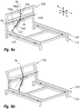
- Fig. 6a and 6b agrees with the design of the Fig. 5a and 5b largely coincide. Deviating from the design of the Fig. 5a and 5b However, no slotted guide is provided to couple the rotational position of the control member 550 with the relative position of the lying part 520 relative to the base part 510. Instead, a linkage connection 540 is provided at the distal end of the lever portion 550b, whose opposite end is pivotally mounted on the cross member 516. As the Fig. 6a and 6b clarify, can Also, such a configuration, the rotational movement of the control member 550 are converted into a translational movement of the lying part 510.
- the control member 650 is mounted on the frame of the lying part 620 about a rotation axis 2a parallel to the bed longitudinal axis 2. Eccentrically to this axis of rotation 2a of the control member 650, a first push rod 640 is articulated to the control member 650 which is articulated at its other end to a boom of the head portion 630. This ensures that a pivoting of the head part 630 relative to the lying part 620 in the in Fig. 7b clarified manner also leads to a rotation of the control member 650 in a clockwise direction.
- a second push rod 642 which extends approximately horizontally obliquely up to an articulation point 644 on the base part 610, is furthermore articulated on the control member 650.
- this second push rod 642 is mounted in a manner not shown both on the control member 650 and on the base part 610 via three-dimensionally acting joints, such as ball joints.
- a rotational movement of the control member 650 is associated with the fact that the lying part 620 moves in the direction of the foot end relative to the base part 610.
- Fig. 8a and 8b again finds a control application, which is similar to the embodiment of the Fig. 5a and 5b has a forcibly guided in a plane guide portion 752.
- the controller 750 in the design of the Fig. 8a and 8b
- the axis of rotation 3a of the control member 750 is therefore pivoted during pivoting of the head part 730 with.
- the management level, along which the guide portion 752 of the control member 750 is guided, is arranged in this case fixed to the lying part 720 at the head end.
- This guide level is spanned by the transverse bed axis 4 and the bed high axis 6.
- the guide portion 752 is provided on a cantilever 750c which extends in a straight line and which kinks from the main portion 750a of the control member 750 in the region of the head part pivot axis 4a.
- the extension arm 750c is likewise always arranged in the same guide plane as the guide section 752.
- the guiding of the guide portion 752 is achieved in the guide plane not by guide surfaces, but via a guide lever 740 which is pivotable about a parallel to the bed longitudinal direction aligned pivot axis 2b. Since this lever 750 is thus movable only parallel to the guide plane, thus guided by him guide portion 752 is correspondingly positively guided.
- the active coupling of the control member 750 with the relative position of the lying part 720 relative to the base part 710 is in a similar manner as in the embodiment of Fig. 7a and 7b realized via an oblique push rod 742, which is fixed by means of a three-dimensionally effective joint on the base part 710. The opposite end of this push rod 742 is connected via a ball joint with the boom 750c.
- a control member 850 is provided, which in a similar manner as in the embodiment of Fig. 5a and 5b is rotatably supported about a part fixed rotation axis 6b.
- a guide section 852 is again provided on a boom 850c, which is forcibly guided in the main extension plane of the head part 830 by a bent U-profile 840.
- the peculiarity of the design of the Fig. 9a and 9b is that the active coupling between the control member 850 and the relative position of the lying part 820 is realized to the base part 810 via a strand, one end of which is attached to the boom 850c, in particular on said guide section 852.
- This strand 842 is first guided in a sleeve 844 to the lying part 820, to which the sleeve 844 is fastened.
- the second strand end is then connected to the base part 810 at an attachment point 846.
- the displacement of the guide section 852 in the U-profile 840 that accompanies the pivoting of the head part 830 causes the strand 842 to be pulled out of the strand sleeve 844 at this end.
- the opposite end of the strand 842 which is attached to the base portion 810, retracts a distance into the sleeve 844 secured to the reclining portion 820 so that as the head portion 830 pivots, the reclining portion 820 toward the foot end abuts the base portion 810 attracts.
- Such a design with two strands accordingly has one strand for each transfer direction of the bedstead.
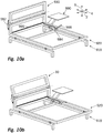
- the design of the 10a and 10b has the essential difference to the preceding embodiments, that the active coupling between the position of the head part 930 to the lying part 920 with the relative position of the lying part 920 to the base part 810 via two hydraulic cylinders 982, 984 is achieved, which are connected to each other via a hydraulic line 986.
- a different cross-sectional area of these hydraulic cylinders 982, 984 is achieved that a displacement of the piston of the hydraulic cylinder 982 is passed in reinforced form to the piston of the hydraulic cylinder 984.
- the hydraulic cylinder 982 is provided between the reclining part 920 and the head part 930.
- the hydraulic cylinder 984 is provided between the base part 910 and the lying part 920.
- a particular advantage in the use of hydraulic cylinders results from the fact that they are available directly with return spring, so that no separate spring device must be provided.
- a blocking device can also be implemented simply, since a check valve on one of the hydraulic cylinders 982, 984 or in the hydraulic line 986 is sufficient for this purpose.
- a blocking lever 988 is provided, which is directly connected to an integrated in the hydraulic cylinder 984 check valve.
- the embodiments of the Fig. 11 to 13 differ significantly from the previous embodiments.
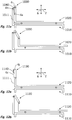
- This embodiment are characterized in that the head part 1030, 1130, 1230 is connected to the base part 1010, 1110, 1210 without the interposition of the lying part 1020, 1120, 1220.
- the connection is in each case designed so that the head part 1030, 1130, 1230 in each case with respect to two degrees of freedom relative to the base part 1010, 1110, 1210 is movable.
- an intermediate lever 1040 is provided, which is pivotally hinged about a parallel to the bed transverse axis pivot axis 4h on a base part fixed boom 1011 and pivotally connected about a pivot axis 4i on the head part 1030.
- These two pivot axes 4h, 4i allow the head part 1030 to be displaceable relative to the extension arm 1011 both rotationally about the pivot axis 4i and also with regard to the vertical position of the pivot axis 4i.
- the user sitting on the bed leans against the head part 1030, he indirectly displaces the lying part 1020 relative to the base part 1010, since the head part 1030 can only be pivoted due to its connection to the arm 1011 due to this displacement of the lying part 1020.
- this embodiment represents a structurally very simple design, which manages with few and inexpensive components.
- a telescopic element 1140 is provided here, which can be displaced along a vertical movement axis 6c relative to the base-part fixed extension 1111. At this telescopic element 1140, the head part 1130 is pivoted directly about the pivot axis 4j.
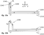
- Fig. 13a and 13b The design according to the Fig. 13a and 13b is again simplified. In this design, no intermediate element is provided. Instead, an elongated hole 1240, which extends along an extension direction 7a, is provided on the head part 1230, in which a transverse pin 1242 provided on the arm is displaceably mounted.
- This combination of a slot 1240 and a pin 1242 inserted therein leads directly to two degrees of freedom, since the head part 1230 relative to the bolt 1242 both in the direction 7a of the extension of the slot 1240 is translationally displaceable and about the pin axis 4k is pivotable.
- the design of the Fig. 13a to 13b is therefore considered to be the simplest variant of an active coupling of the pivoting position of the head part 1230 with the relative position of the lying part 1220 relative to the base part 1210.
- the coupling mechanism between the head part on the one hand and the lying part and base part on the other hand in each case only shown in a simple design to make the drawings easily detectable.
Landscapes
- Health & Medical Sciences (AREA)
- General Health & Medical Sciences (AREA)
- Nursing (AREA)
- Invalid Beds And Related Equipment (AREA)
Description
- Die Erfindung betrifft ein Bettgestell nach dem Oberbegriff von Anspruch 1.
- Gattungsgemäße Bettgestelle sind aus dem Stand der Technik, beispielsweise der
DE 202006004074 U1 , bekannt. Bei diesen gattungsgemäßen Bettgestellen sind das Basisteil und das Liegeteil zumeist fest miteinander verbunden, so dass auch die auf ein solches Bettgestell aufgelegte Matratze ortsfest zu einem Untergrund ist. Das Kopfteil, welches sich am Kopfende üblicherweise vertikal nach oben erstreckt, dient einerseits ästhetischen Zwecken und erlaubt es andererseits, eine Sitzposition auf dem Bett einzunehmen, bei der das Kopfteil als Rückenlehne genutzt wird. Das Kopfteil selbst bildet dabei keinen Teil des Aufnahmebereichs für die Matratze oder Matratze selbst. - Als nachteilig an dem aus dem Stand der Technik bekannten Bettgestellen wird angesehen, dass die Sitzposition, die üblicherweise genutzt wird, um im Bett mit angehobenem Oberkörper lesen zu können, aufgrund der vertikalen Ausrichtung des Kopfteils wenig bequem ist. Zwar lässt sich dies durch zwischen dem Kopfteil und dem Rücken angeordnete Kissen verbessern, eine optimale Leseposition kann dadurch jedoch häufig dennoch nicht erreicht werden.
- Eine denkbare Möglichkeit zum Verbessern eines solchen gattungsgemäßen Bettgestells liegt darin, das Kopfteil schwenkbar am Kopfende des Basisteils und des Liegeteils anzuordnen, so dass es um beispielsweise 30° nach hinten verkippt eine zweckmäßig ausgerichtete Lehnenfläche bildet. Aufgrund der Tatsache, dass üblicherweise jedoch das Kopfende eines Bettes nicht frei im Raum steht, sondern bündig an einer Wand angeordnet wird, ist eine derartige Lösung wohl in den meisten Fällen nicht praktikabel, da der Raum nicht vorhanden ist, den ein solches Verschwenken erfordert.
- Während gattungsgemäße Bettgestelle stets den Charakter eines Bettgestells haben, gibt es auch Sitzmöbelstücke, die sich in Liegemöbelstücke überführen lassen. Solche sind beispielsweise bekannt aus den folgenden Dokumenten:
DE 29820849 U1 ,FR 758281 A US 5,678,264 A ,US 4,731,888 A undDE 1072785 B . - Aus der
FR 2641173 A1 DE 3210986 A1 sind Sofas bekannt, die sich zu Betten umbauen lassen. Ein Kopfteil im Sinne gattungsgemäßer Sitzmöbelstücke weisen diese jedoch nicht auf. - Aufgabe der Erfindung ist es, ein gattungsgemäßes Bettgestell zur Verfügung zu stellen, das oben beschriebene Problematik beseitigt oder zumindest vermindert.
- Erfindungsgemäß wird dies durch ein Bettgestell nach Anspruch 1 erzielt erzielt" bei dem vorgesehen ist, dass das Liegeteil gegenüber dem Basisteil entlang eines Liegeteilbewegungspfades, der sich zumindest auch in Bettlängsrichtung erstreckt, beweglich gelagert ist und das Kopfteil um eine in Bettquerrichtung erstreckte Kopfteilschwenkachse schwenkbar am Liegeteil oder am Basisteil angelenkt ist.
- Im Zusammenhang mit der Beschreibung der vorliegenden Erfindung bezeichnet die Betthochachse eine bezogenen auf einen ebenen Untergrund in vertikale Richtung erstreckte Achse, die Bettlängsachse eine Achse, die sich vom Kopfende des Bettgestells zu dessen Fußende erstreckt, und die Bettquerachse eine zur Betthochachse und Bettlängsachse orthogonale dritte Raumachse.
- Das erfindungsgemäße Bettgestell zeichnet sich dadurch aus, dass das Liegeteil gegenüber dem Basisteil entlang des Liegeteilbewegungspfades beweglich ist. Das Liegeteil kann daher in Richtung der Bettlängsachse gegenüber dem Basisteil verlagert werden. Durch ein Verlagerung des Liegeteils in Richtung des Fußendes wird somit am Kopfende Platz geschaffen, damit das Kopfteil aus einer vorzugsweise vertikalen Grundstellung in eine angewinkelte Komfortstellung gebracht werden kann, ohne dass dadurch die Liegefläche des Bettes verkürzt wird oder das Kopfteil derart verschwenkt werden muss, dass es signifikant über die Erstreckung in der Grundstellung nach außen hinausragt.
- Der Basisteil ist dafür vorgesehen, ortsfest aufgestellt zu werden und hat vorzugsweise hierfür Auflagebereich wie Füße oder dergleichen. Das Liegeteil ist oberhalb des Basisteils angeordnet und weist einen Aufnahmebereich auf, der dafür vorgesehen ist, eine Matratze zu tragen. Der Aufnahmebereich muss dabei nicht in unmittelbarem Kontakt zur Matratze kommen. Es kann ebenfalls vorgesehen sein, dass der Aufnahmebereich dafür vorgesehen ist, eine Auflagefläche oder einen Lattenrost für die Aufnahme der Matratze zu stützen. Der Aufnahmebereich ist ausreichend groß, um einen handelsübliche Matratze von mindestens 180cm auf 80cm aufnehmen zu können bzw. umlaufend zu stützen. Das Kopfteil ist vorzugsweise schwenkbar am Kopfende des Liegeteils angelenkt, so dass eine translative Verlagerung des Liegeteils gleichzeitig eine translative Verlagerung des Kopfteils bewirkt. Die Verlagerbarkeit des Liegeteils gegenüber dem Basisteil ist im einfachsten Falle auf eine translative Beweglichkeit in Richtung der Bettlängsachse beschränkt. Es sind jedoch auch Gestaltungen von der Erfindung umfasst, bei denen zusätzlich eine Kippbeweglichkeit oder eine vertikale Beweglichkeit des Liegeteils gegenüber dem Basisteil vorgesehen ist.
- Die Bewegbarkeit des Liegeteils gegenüber dem Basisteil beträgt in Bettlängsrichtung vorzugsweise mindestens 10cm, insbesondere vorzugsweise mindestens 20cm. Die Schwenkbeweglichkeit des Kopfteils beträgt vorzugsweise mindestens 10°, insbesondere vorzugsweise mindestens 30°.
- Zum Zwecke der translativen Beweglichkeit des Liegeteils gegenüber dem Basisteil ist vorzugsweise eine Schienenführung vorgesehen. Dabei wird unter einer Schienenführung ein Führungssystem verstanden, welches zum einen Rollkörper zwischen dem Liegeteil und dem Basisteil aufweist und zum anderen zumindest in Bettquerrichtung eine Relativbeweglichkeit zwischen dem Basisteil und dem Liegeteil verhindert oder zumindest stark einschränkt. Die Rollkörper können am Basisteil oder am Liegeteil angebracht sein und auf einer Gegenfläche am jeweils anderen Teil abrollen. Die Seitenführung kann von den Rollkörpern und der Gegenfläche separat vorgesehen sein. Es ist jedoch auch denkbar, die Rollkörper und die Gegenfläche derart auszugestalten, dass sie unmittelbar auch die Seitenführung bewirken, beispielsweise indem die Gegenfläche in Form einer Nut ausgestaltet ist, in der die Rollkörper abrollen. Besonders bevorzugt ist es, wenn die Gegenfläche durch einen umlaufenden Rahmen des Basisteils oder des Liegeteils selbst gebildet wird, da dadurch auf eine hiervon separate Gegenfläche oder Schiene verzichtet werden kann.
- Alternativ zu der Gestaltung mit einer Schienenführung ist es möglich, mindestens zwei jeweils drehbar am Basisteile einerseits und am Liegeteil andererseits gelagerte Hebel mit jeweils voneinander abweichenden Drehachsen am Basisteil und am Liegeteil vorzusehen. Die Drehachsen dieser Hebel am Basisteil und am Liegeteil sind vorzugsweise in Bettquerrichtung ausgerichtet. Bei einer Gestaltung der beiden Hebel derart, dass der Abstand zwischen den jeweiligen Drehachsen am Liegteil und Basisteil identisch ist, erlauben diese Hebel eine Parallelverlagerung des Liegeteils gegenüber dem Basisteil, bei der das Liegeteil gleichzeitig in Richtung des Fußendes und in Richtung der Betthochachse nach oben verlagert wird. Dies kann von Vorteil sein, da die Verlagerung nach oben automatisch zu einer Rückstellkraft führt, die das Liegeteil wieder nach unten und in Richtung des Kopfendes drückt.
- Es ist auch denkbar, dass die Hebel sich hinsichtlich des Abstandes zwischen der Drehachse am Liegeteil und der Drehachse am Basisteil voneinander unterscheiden oder dass der Abstand der basisteilseitigen Drehachsen einerseits und der liegeteilseitigen Drehachsen andererseits sich voneinander unterscheiden. Hierdurch kann erreicht werden, dass eine Verlagerung des Liegeteils in Richtung des Fußendes gleichzeitig zu einem stärkeren Anheben des Liegeteils am Fußende führt. Dies kann zum Erreichen einer bequemen Sitz- und Lesestellung auf dem Bett gewünscht sein.
- Die genannten Varianten mit einer Schienenführung einerseits und mit Hebeln andererseits lassen sich auch kombinieren. So kann das Liegeteil im Bereich seines Kopfendes durch eine Schienenführung am Basisteil geführt sein, während am Fußende ein Hebel vorgesehen ist, der einerseits am Liegeteil und andererseits am Basisteil angelenkt ist. Dies führt dazu, dass das Liegeteil im Bereich des Fußendes bei einer Verlagerung in Richtung des Fußendes angehoben wird, während es im Bereich des Kopfendes keine vertikale Verlagerung erfährt.
- Bei einer Weiterbildung der Erfindung sind das Basisteil und das Liegeteil über eine Kopplungseinrichtung miteinander verbunden, wobei diese Kopplungseinrichtung derart ausgebildet ist, dass das Liegeteil oder der Aufnahmebereich des Liegeteils zwangsgesteuert zumindest partiell angehoben oder abgesenkt wird, wenn das Liegeteil gegenüber dem Basisteil entlang des Liegeteilbewegungspfades verlagert wird. Dies ermöglicht es beispielsweise, beim Einnehmen einer bequemen Sitzstellung und dem damit einhergehenden Verlagern des Liegeteils in Richtung des Fußendes den Aufnahmebereich und damit die darauf aufliegende Matratze des Bettes im Bereich der Knie anzuheben um somit eine noch bequemere Sitzposition zu ermöglichen.
- Erfindungsgemäß ist vorgesehen, dass die Relativlage des Liegeteils zum Basisteil und die Relativlage des Kopfteils zum Basisteil bzw. zum Liegeteil miteinander wirkgekoppelt sind, so dass ein Verschwenken des Kopfteils aus einer Grundstellung mit im Wesentlichen vertikal ausgerichteter Frontfläche in eine Komfortstellung mit verschwenkter Frontfläche gleichzeitig mit einer Verlagerung des Liegeteils in Richtung des Fußendes einhergeht.
- Dies erlaubt es, dass ein auf dem Bett sitzender Benutzer durch Zurücklehnen das Kopfteil unmittelbar verschwenkt und dadurch gleichzeitig mittelbar die Verlagerung des Liegeteils gegenüber dem Basisteil bewirkt. Dies ist zum einen sehr einfach zu handhaben und sehr bequem, da ein getrenntes Verschwenken des Kopfteils und Verlagern des Liegeteils nicht erforderlich ist. Zum anderen wird hierdurch automatisch gewährleistet, dass das Kopfteil nicht an der Wand hinter dem Bett anstößt, da das Verschwenken des Kopfteils bei einer Gestaltung mit einer Anlenkung des Kopfteils am Liegeteil auch gleichzeitig eine Verlagerung des Kopfteils in Richtung des Fußendes bewirkt.
- Die Wirkkopplung ist vorzugsweise derart beschaffen, dass ein Verschwenken des Kopfteils um 20° eine Verlagerung des Liegeteils gegenüber dem Basisteil um mindestens 10cm in Richtung der Bettlängsachse bewirkt.
- Die Wirkkopplung zwischen der Relativlage des Liegeteils zum Basisteil einerseits und des Kopfteils zum Basisteil oder vorzugsweise zum Liegeteil andererseits kann auf verschiede Arten erzielt werden. Als besonders bevorzugt wird es angesehen, wenn die Relativlage des Liegeteils zum Basisteil einerseits und die Relativlage des Kopfteils zum Basisteil und/oder zum Liegeteil andererseits mechanisch miteinander wirkgekoppelt sind.
- Eine solche mechanische Wirkkopplung kann über Maschinenelemente wie Zahnräder, Hebel, Ketten, Seilzüge und ähnliches einfach realisiert werden. Daneben umfasst eine mechanische Wirkkopplung auch hydraulische oder pneumatische Lösungen, bei denen Kolben zwischen dem Basisteil und dem Liegeteil einerseits und zwischen dem Kopfteil und dem Liegeteil oder dem Basisteil andererseits vorgesehen sind.
- Eine Variante einer solchen mechanischen Wirkkopplung sieht vor, dass das Kopfteil am Liegeteil um die Kopfteilschwenkachse schwenkbar gelagert ist und eine Anbindung des Kopfteils an das Basisteil ohne Zwischenschaltung des Liegeteils vorgesehen ist, durch die jeder Position der Kopfteilschwenkachse entlang des Liegeteilbewegungspfades eine Schwenkstellung des Kopfteils um die Kopfteilschwenkachse zugeordnet ist. Diese Anbindung des Kopfteils an das Basisteil muss nicht unmittelbar erfolgen, sondern kann durch ein vom Liegeteil verschiedenes Zwischenglied erfolgen. Die Anbindung des Kopfteils an das Basisteil führt zu einer limitierten Beweglichkeit des Kopfteils gegenüber dem Basisteil. Diese limitierte Beweglichkeit des Kopfteils gegenüber dem Basisteil führt in Verbindung mit der ebenfalls limitierten Beweglichkeit der Kopfteilschwenkachse entlang des Liegeteilbewegungspfades dazu, dass ein durch den Benutzer verursachtes Verschwenken des Kopfteils eine translative Verlagerung des Liegeteils gegenüber dem Basisteil bewirkt. Bei einer solchen Gestaltung ist somit das Liegeteil mit dem Basisteil unmittelbar nur über jene Bauteile gekoppelt, die der Beweglichkeit des Liegeteils gegenüber dem Basisteil dienen, beispielsweise also der Schienenführung. Die tatsächliche Bewegung des Liegeteils gegenüber dem Basisteil wird dann durch das Kopfteil bewirkt, welches im Zuge des Verschwenkens auch die Kopfteilschwenkachse und damit das dazu ortsfeste Liegeteil bewegt.
- Die Anbindung des Kopfteils an das Basisteil ist vorzugsweise derart ausgebildet, dass das Kopfteil entweder einerseits translativ entlang einer kopfteilfesten oder basisteilfesten Schiebeachse und andererseits rotativ um eine Drehachse gegenüber dem Basisteil beweglich ist oder aber um eine basisteilfeste Drehachse einerseits und um eine davon fest beabstandete kopfteilfeste Drehachse andererseits rotativ beweglich ist. Beide Gestaltungen erlauben es, dass das Kopfteil gegenüber dem Basisteil einerseits verschwenkt und andererseits vertikal verlagert werden kann.
- Eine Gestaltung mit einem translativen Freiheitsgrad kann beispielsweise derart aussehen, dass ein Zwischenglied gegenüber dem Basisteil linear teleskopierbar ist und das Kopfteil um eine zum Zwischenglied ortsfeste Drehachse an diesem Zwischenglied angelenkt ist. Die Schiebeachse kann jedoch auch kopfteilfest vorgesehen sein, beispielsweise über ein kopfteilfestes Langloch, in dem ein am Basisteil befestigter Bolzen beweglich ist. Die letztgenannte Gestaltung gestattet mit nur zwei Komponenten sowohl die translative als auch die rotative Beweglichkeit des Kopfteils.
- Eine Gestaltung mit zwei Drehachsen kann beispielsweise derart ausgebildet sein, dass ein Zwischenhebel um eine erste Drehachse am Basisteil angelenkt ist und eine zweite Drehachse am Kopfteil angelenkt ist.
- Eine hiervon grundsätzlich abweichende Gestaltung, bei der eine Anbindung des Kopfteils ohne Zwischenschaltung des Liegeteils an das Basisteil nicht zwingend vorgesehen sein muss, sieht vor, dass das Kopfteil am Liegeteil um die Kopfteilschwenkachse schwenkbar gelagert ist und dass ein Steuerorgan vorgesehen ist, welches um eine zu der Kopfteilschwenkachse nichtparallele Steuerorgandrehachse drehbar an einem Lagerteil aus der Gruppe umfassend das Liegeteil, das Basisteil und das Kopfteil gelagert ist. Dabei ist die Drehstellung des Steuerorgans gegenüber dem Lagerteil über eine erste Wirkkopplung mit der Schwenkstellung des Kopfteils gekoppelt und über eine zweite Wirkkopplung mit der Relativstellung des Liegeteils gegenüber dem Basisteil wirkgekoppelt, wobei hierfür ein Kopplungsglied an einem entlang eines Bewegungspfades beweglichen exzentrischen Angriffspunkt des Steuerorgans angreift, durch welches die zweite Wirkkopplung mit dem Liegeteil und/oder dem Basisteil hergestellt ist.
- Kern dieser Gestaltung ist das genannte Steuerorgan, welches um eine zur Kopfteilschwenkachse nichtparallele Achse am Lagerteil gelagert ist. Zwar können auch Gestaltungen mit einem Steuerorgan, dessen Drehachse zur Kopfteilschwenkachse parallel verläuft, zweckmäßig sein, da jedoch das Steuerorgan zur Übertragung von Kräften vom Kopfteil auf das Basisteil aufgrund großer erforderlicher Hebellängen vergleichsweise groß sein kann, ist eine Anordnung des Steuerorgans mit zur Kopfteilschwenkachse paralleler Drehachse sowohl unterhalb des Liegeteils als auch auf der dem Liegeteil abgewandten Seite des Kopfteils nur schwer möglich. Bei der Parallelität der Drehachse des Steuerorgans zur Kopfteilschwenkachse ist allerdings eine Anordnung des Steuerorgans in Bettquerrichtung neben dem Liegeteil unproblematisch möglich. Eine solche Gestaltung ist jedoch aus ästhetischen Gründen nicht immer akzeptabel.
- Dieses Problem wird über die nichtparallele Drehachse des Steuerorgans zur Kopfteilschwenkachse gelöst. Diese Ausrichtung der Drehachse gestattet eine Anordnung des Steuerorgans beispielsweise unter dem Liegeteil mit im Wesentlichen vertikal ausgerichteter Drehachse des Steuerorgans, wobei diese Anordnung unterhalb des Liegeteils die ästhetische Qualität des Bettgestells nicht schmälert.
- Mit der Drehung des Steuerorgans wird der am Steuerorgan vorgesehene Angriffspunkt, der fest oder variabel gegenüber der Drehachse des Steuerorgans beabstandet ist, ebenfalls in gleichem Maße wie das Steuerorgan mitgedreht, wobei dies über das Wirkkopplungsglied die Verlagerung des Liegeteils gegenüber dem Basisteil verursacht. Da der Angriffspunkt zur Erzielung einer großen Verlagerung des Liegeteils gegenüber dem Basisteil zumindest phasenweise vergleichsweise weit von der Drehachse des Steuerorgans entfernt ist, nimmt der Bewegungspfad, entlang dessen der Angriffspunkt beim Drehen des Steuerorgans bewegt wird, erheblichen Platz ein.
- Es wird daher Varianten als vorteilhaft angesehen, bei denen der Bewegungspfad in einer ortsfest zum Kopfteil erstreckten Ebene verläuft, in einer ortsfest zum Liegeteil erstreckten Ebene verläuft, die durch die Bettquerachse und die Betthochachse aufgespannt wird, oder aber in einer ortsfest zum Basisteil und/oder Liegeteil horizontal erstreckten Ebene verläuft.
- Bei der ersten dieser Varianten wird die üblicherweise etwa flächige Gestaltung des Kopfteils genutzt, um hier den Bewegungspfad des Angriffspunktes unterzubringen. Vorzugsweise verläuft der Bewegungspfad dabei in einer Ebene, die zur Frontfläche des Kopfteils parallel ausgerichtet ist.
- Die zweite Variante sieht vor, dass der Bewegungspfad des Angriffspunktes in einer vertikalen Ebene und vorzugsweise am Kopfende des Bettgestells verläuft. Auch hier ist ausreichend Raum, um den Bewegungspfad aufzunehmen, ohne dass dies die gestalterischen Freiheiten des Möbeldesigners stark beeinträchtigt.
- Die dritte Variante sieht vor, dass der Bewegungspfad in einer horizontal erstreckten Ebene verläuft. Diese Ebene ist vorzugsweise unterhalb des Liegeteils angeordnet, also ebenfalls an einer uneinsehbaren Stelle, an der ausreichend Platz für das Steuerorgan und den Bewegungspfad vorhanden ist und der unter gestalterischen Aspekten keine Einschränkung für den Möbeldesigner darstellt.
- Als Lagerteil des Steuerorgans kommen das Basisteil, das Liegeteil und das Kopfteil in Frage. Bei einer bevorzugten Gestaltung bilden das Basisteil oder das Liegeteil das Lagerteil und das Steuerorgan ist um eine vertikale Achse oder zumindest im Wesentlichen vertikale Achse (±25°, vorzugsweise ±15°) drehbar gelagert. Diese Gestaltung ist insbesondere zweckmäßig, wenn der Bewegungspfad des Angriffspunktes unterhalb des Liegeteils angeordnet sein soll.
- Eine alternative Gestaltung sieht vor, dass das Liegeteil das Lagerteil bildet und dass das Steuerorgan um eine in Bettlängsrichtung erstreckte horizontale Drehachse oder zumindest im Wesentlichen horizontale Drehachse (±25°, vorzugsweise ±15°) drehbar ist.
- Eine besondere Ausgestaltung sieht vor, dass das Kopfteil das Lagerteil des Steuerorgans ist, wobei dann vorzugsweise die Drehachse des Steuerorgans parallel zur Frontfläche des Kopfteils ausgerichtet ist.
- Zur Herstellung der ersten Wirkkopplung zwischen der Schwenkstellung des Kopfteils und der Drehstellung des Steuerorgans gegenüber dem Lagerteil sind viele Gestaltungen möglich. Die folgenden Varianten werden insbesondere bevorzugt.
- Bei einer erstgenannten Variante ist ein starres Schubglied vorgesehen, welches einerseits exzentrisch am Steuerorgan und andererseits am Kopfteil oder am Liegeteil angelenkt ist, je nachdem welches dieser Teile nicht das Lagerteil des Steuerorgans bildet. Ein Verschwenken des Kopfteils gegenüber dem Liegeteil führt so zu einer Verlagerung des Anlenkpunktes des Schubglieds und somit zu einer Verdrehung des Steuerorgans.
- Bei einer zweiten Variante sind mindestens zwei starre Schubglieder vorgesehen, wobei ein erstes dieser Schubglieder exzentrisch am Steuerorgan und ein zweites dieser Schubglieder am Kopfteil angelenkt ist und wobei die beiden Schubglieder miteinander über mindestens ein drehbar an einem der Teile gelagertes Umlenkorgan miteinander gekoppelt sind. Diese zweite Variante ist insbesondere dann zweckmäßig, wenn das Steuerorgan um eine vorzugsweise vertikale Drehachse gelagert ist, die nicht im Bereich des Kopfendes des Bettgestells vorgesehen ist. Bei einer solchen Variante kann das zweite Schubglied genutzt werden, um die Schwenkbewegung des Kopfteils nach unten bis auf die Höhe des Liegeteils oder des Basisteils zu übertragen, wo mittels des schwenkbaren Umlenkorgans die Kraft in das erste Schubglied weitergegeben wird, welches sich im Wesentlichen horizontal unterhalb des Liegeteils oder neben dem Liegeteil bis zum Steuerorgan erstreckt.
- Eine besondere Variante ist die dritte Variante, bei der ortsfest am Steuerorgan, jedoch exzentrisch zur Drehachse des Steuerorgans, ein Führungsabschnitt vorgesehen ist, der über Führungsmittel in einer zum Kopfteil oder zum Liegeteil ortsfesten Führungsebene zwangsgeführt ist, wobei diese Führungsebene ortsfest zu jenem Teil ist, welches nicht das Lagerteil darstellt. Bei dieser dritten Variante erfolgt die Einkopplung der Schwenkbewegung des Kopfteils gegenüber dem Liegeteil in das Steuerorgan unmittelbar, da die Zwangsführung des Führungsabschnitts des Steuerorgans in der Führungsebene für jede Schwenkstellung des Kopfteils gegenüber dem Liegeteil nur eine definierte Drehstellung des Steuerorgans gegenüber dem Lagerteil zulässt. Dabei wird es als besonders bevorzugt angesehen, wenn der Führungsabschnitt an einem Ausleger des Steuerorgans angebracht ist, der sich bei der Bewegung des Kopfteils stets in etwa parallel zur Führungsebene erstreckt. Dadurch ist es möglich, diesen Ausleger nach außen vollständig unsichtbar im Liegeteil und im Kopfteil unterbringen zu können.
- Die Führungsmittel zur Führung des Führungsabschnitts des Steuerorgans in der Führungsebene können bei einer ersten Gestaltung zwei einander gegenüberliegende Führungsflächen aufweisen, die auf gegenüberliegenden Seiten des Führungsabschnitts des Steuerorgans angeordnet sind. Je nach Schwenkrichtung des Kopfteils gegenüber dem Liegeteil wird der Führungsabschnitt dann über jeweils eine dieser Führungsflächen zwangsgeführt. Eine hierzu alternative Gestaltung sieht vor, dass ein Führungshebel vorgesehen ist, der am Führungsabschnitt schwenkbar angelenkt ist und der um eine zur Führungsebene orthogonale Führungshebelachse ebenfalls schwenkbar gelagert ist. Da dieser Führungshebel lediglich parallel zur Führungsebene beweglich ist, zwingt er den Führungsabschnitt ebenfalls zu einer kreissegmentförmigen Bewegung parallel zur Führungsebene.
- Hinsichtlich der zweiten Wirkkopplung, die zwischen der Drehstellung des Steuerorgans gegenüber dem Lagerteilteil einerseits und der Relativstellung des Liegeteils gegenüber dem Basisteil andererseits vorgesehen ist, sind wiederum mehrere Varianten denkbar.
- Eine erste bevorzugte Variante sieht vor, dass eine Kulissenführung mit einer Kulissenausnehmung und einem Kulissenschieber vorgesehen ist, durch die das Steuerorgan mit dem Basisteil oder dem Liegeteil verbunden ist. Bei einer Drehbewegung des Steuerorgans wird der Kulissengleiter in der Kulissenausnehmung verschoben und bewirkt dabei eine Relativverlagerung des Liegeteils gegenüber dem Basisteil. Die Kulissenausnehmung kann einerseits am Liegeteil oder am Basisteil und andererseits auch am Steuerorgan selbst vorgesehen sein. Der Kulissengleiter ist am jeweils anderen Teil angebracht.
- Eine zweite Variante hinsichtlich dieser zweiten Wirkkopplung sieht vor, dass ein Schubglied genutzt wird, welches einerseits am Angriffspunkt des Steuerorgans angelenkt ist und welches andererseits am Basisteil oder am Liegeteil angelenkt ist. Eine solche Gestaltung mit einem starren Schubglied ist sehr einfach zu realisieren. Bei einer Gestaltung der Lagerung des Steuerorgans mit nicht vertikaler Drehachse ist allerdings zu beachten, dass dreidimensional wirkende Gelenke wie Kugelgelenke zweckmäßig sind, da sich der Eingriffspunkt am Steuerorgan in diesem Fall bei einer Drehbewegung des Steuerorgans auch vertikal verlagert.
- Eine dritte bevorzugte Variante sieht vor, dass ein flexibler Strang genutzt wird, der am Angriffspunkt des Steuerorgans befestigt ist und der durch eine Strangführung am Basisteil oder am Liegeteil bis zu einer Befestigung am jeweils anderen der beiden Teile geführt ist. Ein solcher Strang kann als rein auf Zug belastbarer Strang oder auch als zur Aufnahme von Zug- und Druckkräften ausgebildeter Strang gestaltet sein. Auch eine Gestaltung mit zwei jeweils nur auf Zug belastbaren Strängen, die in Abhängigkeit der Bewegungsrichtung des Kopfteils die Kräfte übertragen, ist dabei umfasst. Die Strangführung kann beispielsweise durch einfache Umlenkrollen oder auch durch eine sich entlang des Stranges erstreckende Stranghülse, in der der Strang geführt ist, gebildet werden. Die Gestaltung mit einem flexiblen Strang als Wirkkopplungsglied ist vor allem von Vorteil, wenn der Bewegungspfad des Angriffspunktes in einer zum Kopfteil ortsfesten Ebene liegt, da über einen Strang in einfacher Art und Weise die Überführung der Kräfte vom Kopfteil in das Liegeteil und das Basisteil möglich ist.
- Bei einer Weiterbildung der Erfindung ist ein manuell aktivierbares und/oder deaktivierbares Blockiermittel vorgesehen, durch welches die Relativbeweglichkeit des Kopfteils, des Liegeteils und/oder des Basisteils zueinander blockiert werden kann, wobei das Blockiermittel vorzugsweise unmittelbar die Relativbeweglichkeit zwischen dem Basisteil und dem Liegeteil blockiert und mittelbar die Relativbeweglichkeit des Kopfteils gegenüber dem Basisteil bzw. dem Liegeteil blockiert.
- Durch ein solches Blockiermittel kann eine einmal festgelegte Schwenkstellung des Kopfteils gegenüber dem Liegeteil und/oder Relativstellung des Liegeteils gegenüber dem Basisteil arretiert werden. Vorzugsweise ist das Blockiermittel derart gestaltet, dass es ohne manuelles Zutun in einem blockierenden Zustand verharrt und manuell deaktiviert werden muss, um die Schwenkstellung des Kopfteils gegenüber dem Liegeteil zu verändern. Alternativ ist jedoch auch eine Gestaltung denkbar, bei der das Blockiermittel bistabil ausgeführt ist und in einem einmal hergestellten blockierenden und einem nicht blockierenden Zustand jeweils verbleibt, bis es manuell in den jeweils anderen Zustand überführt wird. Das Blockiermittel kann auch so ausgebildet sein, dass es nur in eine Bewegungsrichtung wirkt und so im aktivierten Zustand beispielsweise lediglich die Rückführung in die Grundstellung des Bettgestells verhindert.
- Die Gestaltung des Blockiermittels zum unmittelbaren Blockieren der Beweglichkeit des Liegeteils gegenüber dem Basisteil ist vorteilhaft, da diese Relativbeweglichkeit verglichen mit der Relativbeweglichkeit des Kopfteils gegenüber dem Liegeteil vergleichsweise groß ist, so dass die auftretenden Kräfte, gegen die die Blockieren wirken muss, vergleichsweise klein sind.
- Ebenfalls von Vorteil ist eine Gestaltung, bei der das erforderliche Schwenkmoment am Kopfteil zur wirkgekoppelten Verlagerung des Liegeteils bei einem Verschwenken aus der Grundstellung in die Komfortstellung zunächst über einen Bereich zwischen 0,5° bis 3° Größe gegenüber dem nachfolgend erforderlich Schwenkmoment erhöht ist, so dass ein ungewolltes Verschwenken des Kopfteils verhindert wird.
- Bei einer Weiterbildung der Erfindung ist mindestens ein Kraftbeaufschlagungsmittel mit Energiespeicher, vorzugsweise ein Federmittel vorgesehen, durch welches das Liegeteil in Richtung einer Endlage in Richtung des Kopfendes relativ zum Basisteil kraftbeaufschlagt wird und/oder das Kopfteil in Richtung einer Stellung, in der die Frontfläche vertikal ausgerichtet ist, momentenbeaufschlagt wird.
- Ein solches Kraftbeaufschlagungsmittel mit Energiespeicher dient dem Zweck, durch während der Überführung des Bettgestells in die Komfortstellung aufgenommene Energie in Richtung der Grundstellung des Bettgestells zu wirken. Eine Ausgestaltung dessen umfasst ein Gewicht, welches angehoben wird und dessen potentielle Energie zur Rückführung des Bettgestells in die Grundstellung dient. Bevorzugt ist allerdings die Gestaltung mit einem Federmittel, gegen dessen Federkraft das Verschwenken des Kopfteils in Richtung der Komfortstellung erfolgt. Sobald die hierfür vom Benutzer in das System eingebrachte Kraft wieder entfällt und ein gegebenenfalls vorhandenes Blockiermittel deaktiviert ist, kehrt das Bettgestell somit in die Grundstellung zurück.
- Als besonders vorteilhaft wird es angesehen, wenn am Bettgestell eine Nachttischfläche vorgesehen ist, die ortsfest am Liegeteil befestigt ist. Als eine solche Nachttischfläche wird ein Ablagebereich von vorzugsweise mindestens 20cm x 20cm, insbesondere vorzugsweise mindestens 30cm x 30cm angesehen, der gegenüber dem Liegeteil abgesetzt ist, mit diesem jedoch ortsfest verbunden ist. Der Vorteil der ortsfesten Anbindung am Liegeteil ergibt sich daraus, dass bei einer Verlagerung des Liegeteils in Richtung des Fußendes auch die Nachttischfläche mitverlagert wird. Dies ist zum Einen bequem, da die Nachttischfläche somit unabhängig von der Relativlage des Liegeteils gegenüber dem Basisteil gut zugänglich ist, zum Anderen ist dies jedoch auch deshalb von Vorteil, da ein Kopfteil vorgesehen sein kann, das die Breite des Liegeteils übersteigt und das ansonsten mit einem separat vorgesehenen Nachttisch kollidieren würde, wenn das Liegeteil in Richtung des Fußendes verlagert wird.
- Neben der beschriebenen Gestaltung bei der einem Basisteil jeweils ein Liegeteil und ein Kopfteil zugeordnet sind, ist auch eine alternative Gestaltung für breite Bettgestelle denkbar, bei der jeweils zwei Liegeteile und zwei Kopfteile vorgesehen sind, die voneinander separat die oben beschriebenen Merkmale aufweisen, so dass zwei Benutzer, die ein gemeinsames Bett teilen, die jeweils individuell gewünschte Stellung des Kopfteils gegenüber dem Liegeteil einstellen können, ohne dass der andere Benutzer hierdurch gestört wird.
- Weitere Vorteile und Aspekte der Erfindung ergeben sich außer aus den Ansprüchen auch aus der nachfolgenden Beschreibung von einer Vielzahl bevorzugter Ausführungsformen der Erfindung, die anhand der Figuren erläutert sind. Dabei zeigen
- Fig 1a und 1b
- den Grundaufbau eines erfindungsgemäßen Bettgestells, wobei diese Ausführungsform aufgrund des Fehlens der erfindungsgemäßen Wirkkopplung als solches nicht von der Erfindung umfasst ist,
- Fig. 2a und 2b
- eine erste Ausführungsform eines erfindungsgemäßen Bettgestells in einer Grundstellung und einer Komfortstellung,
- Fig. 3a und 3b
- eine zweite Ausführungsform eines erfindungsgemäßen Bettgestells in einer Grundstellung und einer Komfortstellung,
- Fig. 4a und 4b
- eine dritte Ausführungsform eines erfindungsgemäßen Bettgestells in einer Grundstellung und einer Komfortstellung,
- Fig. 5a und 5b
- eine vierte Ausführungsform eines erfindungsgemäßen Bettgestells in einer Grundstellung und einer Komfortstellung,
- Fig. 6a und 6b
- eine fünfte Ausführungsform eines erfindungsgemäßen Bettgestells in einer Grundstellung und einer Komfortstellung,
- Fig. 7a und 7b
- eine sechste Ausführungsform eines erfindungsgemäßen Bettgestells in einer Grundstellung und einer Komfortstellung,
- Fig. 8a und 8b
- eine siebte Ausführungsform eines erfindungsgemäßen Bettgestells in einer Grundstellung und einer Komfortstellung,
- Fig. 9a und 9b
- eine achte Ausführungsform eines erfindungsgemäßen Bettgestells in einer Grundstellung und einer Komfortstellung,
- Fig. 10a und 10b
- eine neunte Ausführungsform eines erfindungsgemäßen Bettgestells in einer Grundstellung und einer Komfortstellung,
- Fig. 11a und 11b
- eine zehnte Ausführungsform eines erfindungsgemäßen Bettgestells in einer Grundstellung und einer Komfortstellung,
- Fig. 12a und 12b
- eine elfte Ausführungsform eines erfindungsgemäßen Bettgestells in einer Grundstellung und einer Komfortstellung und
- Fig. 13a und 13b
- eine zwölfte Ausführungsform eines erfindungsgemäßen Bettgestells in einer Grundstellung und einer Komfortstellung.
- Die
Fig. 1a und 1b zeigen eine besonders einfache Gestaltung eines Bettgestells. Dieses weist ein Basisteil 10, ein Liegeteil 20 sowie ein Kopfteil 30 auf. Dieses Beispiel dient nur der Verdeutlichung des Grundaufbaus und ist mangels der erfindungsgemäß vorgesehenen Wirkkopplung nicht von der Erfindung umfasst. - Das Basisteil 10 dient der ortsfesten Aufstellung und weist zu diesem Zweck Füße 12 auf. Zwischen den je zwei Füßen 12 auf der gleichen Längsseite des Bettgestells ist jeweils ein in Bettlängsrichtung 2 erstreckter Längsträger 14 vorgesehen, wobei die beiden Längsträger 14 miteinander durch einen Querträger 16 verbunden sind.
- Oberhalb des Basisteils 10 ist das Liegeteil 20 vorgesehen, welches über einen horizontal erstreckten umlaufenden Rahmen 22 verfügt, der einen Aufnahmebereich 23 für ein Lattenrost und eine darauf zu platzierende Matratze bildet. An der Unterseite dieses umlaufenden Rahmens 22 sind insgesamt vier Rollen 24 vorgesehen, die um zur Bettquerachse 4 parallele Drehachsen drehbar gelagert sind. Diese Rollen 24 sind auf die Längsträger 14 des Basisteils 10 aufgesetzt und erlauben dadurch eine Verlagerung des Liegeteils 20 gemeinsam mit dem nachfolgend noch beschriebenen Kopfteil 30 in Richtung der Bettlängsachse 2. Über Führungsbleche 25, die im Bereich einer jeden Rolle 24 vorgesehen sind, ist eine Seitenführung gewährleistet, so dass das Liegeteil 20 nicht in Richtung der Bettquerachse 4 vom Basisteil 10 abrutschen kann.
- Das Kopfteil 30 ist am Kopfende des Liegeteils 20 um eine zur Bettquerachse 4 parallele Kopfteilschwenkachse 4a verschwenkbar angelenkt. Es kann dadurch aus der vertikalen Grundstellung, die in
Fig. 1a dargestellt ist, nach hinten verschwenkt werden. Die Kopfteilschwenkachse 4a ist vorzugsweise zwischen 15cm und 50cm oberhalb des Aufnahmebereichs 23 angeordnet, um zu erreichen, dass bei einer entsprechenden Matratzendicke die Kopfteilschwenkachse 4a etwa auf Höhe der Oberseite der Matratze angeordnet ist. -
Fig. 1b zeigt das Bettgestell derFig. 1a nach der Überführung in die Komfortstellung. In dieser Komfortstellung ist das Liegeteil 20 gegenüber dem Basisteil 10 in Richtung des Fußendes verlagert. Diese Verlagerung gestattet es, dass das Kopfteil 30 nach hinten verschwenkt werden kann, ohne dass das Kopfteil dabei in Bettlängsrichtung 2 signifikant über das Basisteil 10 hinausragt. - Die Komfortstellung der
Fig. 1b ist dafür gedacht, einem Benutzer eine bequeme Sitz- und Lesestellung im Bett zu gewährleisten. Der Benutzer kann auf der nicht dargestellten Matratze sitzend seinen Rücken bequem gegen das in die Komfortstellung verschwenkte Kopfteil lehnen und so eine Leseposition einnehmen, die der Sitzstellung auf einem Sessel ähnelt. - Die Ausführungsform der
Fig. 1a und 1b ist auf das reine Bettgestell beschränkt. Bei einem vollständigen Bett auf Basis eines solchen Bettgestells ist neben einem Lattenrost zur Aufnahme der Matratze vorzugsweise auch eine insbesondere gepolsterte Fläche am Kopfteil 30 angebracht, die die von dem Rahmen 32 des Kopfteils 30 definierte Frontfläche 34 abdeckt. - Bei der Ausführungsform der
Fig. 1a und 1b ist auf die Darstellung von Einstellmitteln und/oder Arretiermitteln zur Beeinflussung und Festlegung der jeweiligen Stellung des Liegeteils 20 gegenüber dem Basisteil 10 und des Kopfteils 30 gegenüber dem Liegeteil 20 verzichtet worden. Vorzugsweise sind solche Mittel vorgesehen, um die Relativlage einzustellen und eine einmal herstellte Einstellung zu fixieren. - Während bei der Ausführungsform der
Fig. 1a und 1b ein separates Einstellen der Relativstellung des Liegeteils 20 gegenüber dem Basisteil 10 und des Kopfteil 30 gegenüber dem Liegeteil 20 erforderlich ist, ist erfindungsgemäß vorgesehen, dass die jeweiligen Relativstellungen miteinander gekoppelt sind, so dass einem jeden Schwenkwinkel des Kopfteils eine Relativlage des Liegeteils gegenüber dem Basisteil zugeordnet ist. Bei den nachfolgend erläuterten Ausführungsformen derFig. 2 bis 13 ist dies der Fall. Diese Ausführungsformen weisen jeweils einen mit der Ausführungsform derFig. 1a und 1b übereinstimmenden Grundaufbau auf, der jeweils nicht mehr einzeln erläutert wird. - Bei der Gestaltung der
Fig. 2a und 2b ist zum Zwecke der Wirkkopplung an einem Steuerfortsatz des Kopfteils 130 eine starre Schubstange 140 vorgesehen, die darüber hinaus an einem Steuerorgan 150 exzentrisch angelenkt ist, welches seinerseits um eine zur Bettquerachse 4 parallele Steuerorgandrehachse 4b drehbar gelagert ist. Wie der Übergang von derFig. 2a zurFig. 2b zeigt, führt ein Verschwenken des Kopfteils 130 gegenüber dem Liegeteil 120 dadurch auch zu einem Verschwenken des Steuerorgans 150 gegenüber dem Liegeteil 120. Das Steuerorgan 150 weist zusätzlich eine Kulissenausnehmung 152 in Form eines Langlochs auf, in die ein am Basisteil befestigter Bolzen 142 als Kulissengleiter hineinragt. Sobald das Steuerorgan 150 in Reaktion auf ein Verschwenken des Kopfteils 130 gedreht wird, wird über diese Kulissenführung auch das Liegeteil 120 gemeinsam mit dem Kopfteil 130 in Richtung der Bettlängsachse 2 zum Fußende hin verlagert. Hierdurch wird erreicht, dass trotz des Verschwenkens des Kopfteils 130 nach hinten das Kopfteil 130 auch in der Komfortstellung derFig. 2b kaum über das Basisteil 110 in Bettlängsrichtung 2 nach links hinausragt. - Die beschriebene Wirkkopplung über das Steuerorgan 150 führt demnach dazu, dass ein durch Benutzer durch Zurücklehnen erzieltes Verschwenken des Kopfteils 130 automatisch auch eine Verlagerung des Liegeteils 120 in Richtung des Fußendes bewirkt. Bei der dargestellten Variante sind die hierfür erforderlichen Komponenten 150, 140, 142 seitlich neben dem Liegeteil 120 angeordnet. Dies erlaubt die dargestellte rein zweidimensionale Lösung, bei der sich alle Komponenten nur in der Ebene der Betthochrichtung 6 und der Bettlängsrichtung 2 verlagern bzw. drehen. Diese Lösung führt jedoch zu dem Problem, dass die Mechanik seitlich des Liegeteils 120 angeordnet ist und daher versteckt werden muss und somit die Gestaltungsfreiheit des Möbeldesigners eingeschränkt wird. Die nachfolgend noch erläuterten Gestaltungen der
Fig. 4 bis 10 lösen dies durch eine dreidimensional wirkende Mechanik. - Das Bettgestell der
Fig. 2a und 2b weist darüber zwei weitere relevante Baugruppen auf. So ist eine Blockiereinrichtung 160 vorgesehen, die einen Blockierklotz aus Gummi 162 aufweist, der beweglich am Liegeteil 120 angelenkt ist und mittels einer Spiralfeder 164 permanent in Richtung des Basisteils 110 kraftbeaufschlagt wird. Ohne manuelle Einflussnahme auf die Blockiereinrichtung stellt sich somit der blockierte Zustand derFig. 2b ein, durch den eine Relativverlagerung des Liegeteils 120 gegenüber dem Basisteil 110 verhindert wird. Eine Deaktivierung dieser Blockiereinrichtung 160 ist über einen hierfür vorgesehenen Hebel 166 manuell möglich, wie inFig. 2a dargestellt ist. Diese manuelle Deaktivierung erfolgt bestimmungsgemäß, bevor der Benutzer des Bettgestells durch Kraftbeaufschlagung des Kopfteils 130 in die Komfortstellung überführt. Nach Erreichen der Komfortstellung derFig. 2b lässt der Benutzer den Hebel 166 los, so dass die Blockiereinrichtung wieder den blockierenden Zustand derFig. 2b einnimmt und somit die eingestellte Komfortstellung auch ohne weitere Kraftbeaufschlagung durch den Benutzer hält. Die zweite nennenswerte weitere Baugruppe ist die Federeinrichtung 170. Diese umfasst eine Schraubenzugfeder 172, die einerseits am Liegeteil 120 und andererseits am Basisteil 110 befestigt ist. Wie dieFig. 2b zeigt, wird diese Feder 172 gedehnt, wenn das Bettgestell in seiner Komfortstellung überführt wird. Hierdurch wird eine Rückstellkraft aufgebaut, die eine Rücküberführung aus der Komfortstellung derFig. 2b in die Grundstellung derFig. 2a alleine durch Lösen der Blockiereinrichtung 160 gestattet. - Aus Gründen der Vereinfachung sind die Baugruppen 160 und 170 bei den anderen Ausführungsformen der Erfindung nicht dargestellt. Gleichwohl sind sie auch bei den anderen Ausführungsformen vorgesehen.
- Bei der Gestaltung der Ausführung der
Fig. 3a und 3b sind keine Rollen zur translativen Führung des Liegeteils 220 gegenüber dem Basisteil 210 vorgesehen. Stattdessen sind zwei Hebel 240, 250 jeweils um zur Bettquerachse 4 parallele Schwenkachsen 4c, 4d, 4e, 4f einerseits am Basisteil 210 und andererseits am Liegeteil 220 schwenkbar gelagert. Diese Hebel 240, 250 gestatten somit eine Parallelverlagerung des Liegeteils 220 gegenüber dem Basisteil 210, wobei das Liegeteil dabei nicht nur in Bettlängsrichtung 2 in Richtung des Fußendes bewegt wird, sondern gleichzeitig in Betthochrichtung 6 leicht angehoben wird. Die Wirkkopplung zur Schwenkstellung des Kopfteils 230 ist in ähnlicher Art und Weise wie bei der Ausführungsform derFig. 2a und 2b realisiert, indem eine Stange 242 oder ein anderweitiges auf Zug belastbares Verbindungsteil einerseits am Kopfteil 230 und andererseits exzentrisch zur Drehachse 4f am kopfteilseitigen Hebel 250 angelenkt ist. Wie sich aus dem Übergang von derFig. 3a zurFig. 3b ergibt, wird somit durch ein Verschwenken des Kopfteils 230 nach hinten der Hebel 250 aufgerichtet, was mit der oben beschriebenen Verlagerung des Liegeteils 220 gegenüber dem Basisteil 210 einhergeht. - Eine erste nicht dargestellte Variante zur Gestaltung der
Fig. 3a und 3b sieht vor, dass der Abstand der Schwenkachsen 4c und 4d zueinander größer ist als der Abstand der Schwenkachsen 4e und 4f zueinander. Dies bewirkt, dass bei einer Überführung des Bettgestells in die Komfortstellung das Fußende des Liegeteils in stärkerem Maße angehoben wird als das Kopfende. Hierdurch lässt sich eine besonders vorteilhafte Komfortstellung realisieren, bei der die Beine des Benutzers in leicht ansteigender Stellung auf der Matratze liegen. - Eine weitere nicht dargestellte Variante zu den vorstehenden Ausführungsformen sieht vor, dass im Bereich des Kopfendes die Gestaltung mit der der
Fig. 2a und 2b übereinstimmt, am Fußende jedoch in der Art derFig. 3a und 3b ein Hebel vorgesehen ist. Hierdurch wird ebenfalls erreicht, dass das Liegeteil bei der Überführung in die Komfortstellung nur partiell im Bereich des Fußendes angehoben wird, während am Kopfende aufgrund der Rollen das Liegeteil nicht angehoben wird. - Bei der Gestaltung der
Fig. 4a und 4b ist ähnlich der Gestaltung derFig. 2a und 2b am Kopfteil 330 eine Schubstange 340 angebracht. Diese wirkt jedoch nicht unmittelbar auf das weitgehend unterhalb des Liegeteils angeordnete Steuerorgan 350, sondern zunächst auf ein um eine zur Bettquerachse 4 parallele Drehachse 4g gelagertes Umlenkorgan 342. An diesem ist eine zweite Schubstange 344 ebenfalls beabstandet zur Schwenkachse 4g des Umlenkorgans 342 angelenkt, welche sich in etwa in Richtung der Bettlängsachse 2 erstreckt und deren gegenüberliegendes Ende mit dem bereits genannten Steuerorgan 350 verbunden ist. Das Steuerorgan 350 ist als Schwenkhebel ausgebildet, der um eine zur Betthochachse 6 parallele Steuerorgandrehachse 6a verschwenkbar am Liegeteil 320 gelagert ist. Der Anlenkpunkt 352 für die zweite Schubstange 344 ist sehr nah an der Schwenkachse 6a vorgesehen. Wesentlich weiter von der Schwenkachse 6a beabstandet und somit eine große Übersetzung bewirkend ist am Steuerorgan eine Kulissenausnehmung 354 vorgesehen, in die ein basisteilfester Bolzen 346 als Kulissengleiter hineinragt. - Wenn das Bettgestell aus der Grundstellung der
Fig. 4a durch Verschwenken des Kopfteils 330 in die Komfortstellung derFig. 4b gebracht werden soll, bewirkt dieses Verschwenken eine Verlagerung der Schubstange 340, daraus resultierend ein Verschwenken des Umlenkorgans 342 und über die zweite Schubstange 344 auch ein Verschwenken des Steuerorgans 350 um die Drehachse 6a. Hierdurch wird die Kulissenausnehmung 354 um etwa 20cm gegenüber dem Liegeteil 320 in Bettlängsrichtung in Richtung des Kopfendes auf einer Kreisbahn verlagert, so dass aufgrund des Bolzens 346 das Liegeteil 320 gemeinsam mit dem Kopfteil 330 in Richtung der Bettlängsachse 2 zum Fußende hin verlagert wird. - Eine nicht dargestellte Variante zu der Gestaltung der
Fig. 4a und 4b sieht vor, dass die Kulissenausnehmung an dem Querträger 316 ortsfest zum Basisteil 310 vorgesehen ist und dass der Kulissengleiter statt am Basisteil 310 am Steuerorgan 350 fest angebracht ist. - Die Gestaltung gemäß der
Fig. 5a und 5b weist ein Steuerorgan 450 auf, welches im Bereich des Kopfendes mittels eines Hauptabschnitts 450a am Liegeteil um eine Drehachse 6b gelagert ist. Ähnlich der Ausgestaltung derFig. 4a und 4b ist an diesem Steuerorgan ebenfalls ein Hebelabschnitt 450b vorgesehen, der über eine Kulissenführung 442, 454 eine Drehbewegung des Steuerorgans 450 in eine translative Bewegung des Liegeteils 420 gegenüber dem Basisteil 410 bewirkt. Hierfür ist bei der konkreten Ausgestaltung derFig. 5a und 5b eine Kulissenausnehmung 442 in einem am Querträger 416 angebrachten Blech 440 vorgesehen, in die ein am Hebelabschnitt 450b befestigter Kulissengleiter 452 eingreift. - Die Besonderheit bei der Gestaltung gemäß der
Fig. 5a und 5b liegt insbesondere in der Wirkkopplung der Schwenkstellung des Kopfteils 430 mit der Drehstellung des Steuerorgans 450. Zum Zwecke dieser Wirkkopplung weist das Steuerorgan 450 an seinem oberen Ende einen Ausleger 450c auf, an dessen Ende ein Führungsabschnitt 452 exzentrisch zur Drehachse 6b angebracht ist. Dieser Führungsabschnitt 452 ist innerhalb eines am Kopfteil 430 befestigten U-Profils 444 geführt, so dass der Führungsabschnitt 452 stets in der Haupterstreckungsebene des Kopfteils 430 verbleibt. - Ausgehend von der Grundstellung der
Fig. 5a bewirkt dies, dass mit zunehmendem Verschwenken des Kopfteils 430 um die Kopfteilschwenkachse 4a auch das gesamte Steuerorgan 450 um die Drehachse 6b mit verschwenkt wird. Dies bewirkt in der oben schon dargelegten Art und Weise die Verlagerung des Liegeteils 420 gemeinsam mit dem Kopfteil 430 gegenüber dem Basisteil 410. - Besonders vorteilhaft an dieser Gestaltung ist es, dass der Ausleger 450c vom Hauptabschnitt 450a des Steuerorgans 450 im Bereich der Kopfteilschwenkachse 4a abknickt und in sich geradlinig ist. Dies führt dazu, dass sich nicht nur der Führungsabschnitt 452, sondern der gesamte Ausleger 450c sich stets parallel zur Hauptersteckungsebene des Kopfteils 430 erstreckt. Hierdurch kann die Wirkkopplung zwischen der Schwenkstellung des Kopfteils 430 und der Drehstellung des Steuerorgans 450 nahezu völlig unsichtbar am Bettgestell vorgesehen sein. Dabei ist es möglich, durch einen ausreichend langen Ausleger 450c ein ausreichend hohes Moment in das Drehorgan 450 einzukoppeln, welches ohne Überbeanspruchung der einzelnen Komponenten ausreicht, um das Liegeteil 420 gegenüber dem Basisteil 410 zu verlagern.
- Eine Besonderheit bei der Gestaltung gemäß der
Fig. 5a und 5b , die jedoch auch bei allen anderen Ausführungsformen Verwendung finden kann, liegt darin, dass in der Grundstellung derFig. 5a die Rollen 424 des Liegeteils 420 in Mulden des Basisteils 410 gelagert sind. Dies führt zu einer Stabilisierung der Grundstellung, da zunächst eine erhöhte Kraft aufgebracht werden muss, um die Grundstellung zu verlassen. So ist auch ohne ein separates Blockiermittel gewährleistet, dass das Kopfteil nicht versehentlich aus seiner vertikalen Grundstellung heraus verschwenkt wird. - Die Ausgestaltung der
Fig. 6a und 6b stimmt mit der Ausgestaltung derFig. 5a und 5b weitgehend überein. Abweichend von der Gestaltung derFig. 5a und 5b ist jedoch keine Kulissenführung vorgesehen, um die Drehstellung des Steuerorgans 550 mit der Relativstellung des Liegeteils 520 gegenüber dem Basisteil 510 zu koppeln. Stattdessen ist am distalen Ende des Hebelabschnitts 550b eine Gestängeverbindung 540 vorgesehen, deren gegenüberliegendes Ende am Querträger 516 schwenkbar gelagert ist. Wie dieFig. 6a und 6b verdeutlichen, kann auch über eine solche Gestaltung die Drehbewegung des Steuerorgans 550 in eine translative Bewegung des Liegeteils 510 überführt werden. - Bei der Ausgestaltung der
Fig. 7a und 7b ist das Steuerorgan 650 um eine zur Bettlängsachse 2 parallele Drehachse 2a am Rahmen des Liegeteils 620 gelagert. Exzentrisch zu dieser Drehachse 2a des Steuerorgans 650 ist eine erste Schubstange 640 am Steuerorgan 650 angelenkt, die mit ihrem anderen Ende an einem Ausleger des Kopfteils 630 angelenkt ist. Hierdurch wird erreicht, dass ein Verschwenken des Kopfteils 630 gegenüber dem Liegeteil 620 in der inFig. 7b verdeutlichten Art und Weise auch zu einem Verdrehen des Steuerorgans 650 im Uhrzeigersinn führt. Um diese Drehbewegung des Steuerorgans 650 in eine translative Bewegung des Liegeteils 620 gegenüber dem Basisteil 610 zu überführen, ist am Steuerorgan 650 weiterhin eine zweite Schubstange 642 angelenkt, die sich in etwa horizontal schräg bis zu einem Anlenkpunkt 644 am Basisteil 610 erstreckt. Dabei ist diese zweite Schubstange 642 in nicht näher dargestellter Art und Weise sowohl am Steuerorgan 650 als auch am Basisteil 610 über dreidimensional wirkende Gelenke, beispielsweise Kugelgelenke, gelagert. Wie ebenfalls dem Übergang von derFig. 7a zurFig. 7b zu entnehmen ist, wird über die genannte Schrägstellung der Schubstange 644 erreicht, dass eine Drehbewegung des Steuerorgans 650 damit einhergeht, dass das Liegeteil 620 sich in Richtung des Fußendes gegenüber dem Basisteil 610 verlagert. - Bei der Gestaltung der
Fig. 8a und 8b findet wiederum ein Steuerorgan Anwendung, welches ähnlich der Ausführungsform derFig. 5a und 5b über einen in einer Ebene zwangsgeführten Führungsabschnitt 752 verfügt. Abweichend von der Gestaltung derFig. 5a und 5b ist das Steuerorgan 750 bei der Gestaltung derFig. 8a und 8b jedoch um eine Drehachse 3a drehbar, die ortsfest zum verschwenkbaren Kopfteil 730 vorgesehen ist. Die Drehachse 3a des Steuerorgans 750 wird daher beim Verschwenken des Kopfteils 730 mit verschwenkt. Die Führungsebene, entlang derer der Führungsabschnitt 752 des Steuerorgans 750 geführt ist, ist in diesem Falle ortsfest zum Liegeteil 720 an dessen Kopfende angeordnet. Diese Führungsebene wird durch die Bettquerachse 4 und die Betthochachse 6 aufgespannt. Wie bereits bei der Gestaltung derFig. 5a und 5b ist der Führungsabschnitt 752 an einem Ausleger 750c vorgesehen, der sich geradlinig erstreckt und der vom Hauptabschnitt 750a des Steuerorgans 750 im Bereich der Kopfteilschwenkachse 4a abknickt. Damit wird auch bei dieser Gestaltung erreicht, dass der Ausleger 750c ebenfalls stets in der gleichen Führungsebene angeordnet ist wie der Führungsabschnitt 752. - Abweichend von der Gestaltung der
Fig. 5a und 5b wird das Führen des Führungsabschnitts 752 in der Führungsebene jedoch nicht durch Führungsflächen erzielt, sondern über einen Führungshebel 740, der um eine parallel zur Bettlängsrichtung ausgerichtete Schwenkachse 2b verschwenkbar ist. Da dieser Hebel 750 somit nur parallel zur Führungsebene bewegbar ist, ist somit auch der durch ihn geführte Führungsabschnitt 752 entsprechend zwangsgeführt. Die Wirkkopplung des Steuerorgans 750 mit der Relativstellung des Liegeteils 720 relativ zum Basisteil 710 ist in ähnlicher Art und Weise wie bei der Ausgestaltung derFig. 7a und 7b über eine schräge Schubstange 742 realisiert, die mittels eines dreidimensional wirksamen Gelenks am Basisteil 710 befestigt ist. Das gegenüberliegende Ende dieser Schubstange 742 ist über ein Kugelgelenk mit dem Ausleger 750c verbunden. - Auch bei der Ausgestaltung gemäß den
Fig. 9a und 9b ist ein Steuerorgan 850 vorgesehen, welches in ähnlicher Art und Weise wie bei der Ausgestaltung derFig. 5a und 5b um eine liegeteilfeste Drehachse 6b drehbar gelagert ist. An diesem Steuerorgan 850 ist wiederum ein Führungsabschnitt 852 an einem Ausleger 850c vorgesehen, der in der Haupterstreckungsebene des Kopfteils 830 durch ein gebogenes U-Profil 840 zwangsgeführt ist. - Die Besonderheit der Gestaltung der
Fig. 9a und 9b liegt darin, dass die Wirkkopplung zwischen dem Steuerorgan 850 und der Relativstellung des Liegeteils 820 zum Basisteil 810 über einen Strang realisiert ist, dessen eine Ende am Ausleger 850c, insbesondere am genannten Führungsabschnitt 852, angebracht ist. Dieser Strang 842 ist in einer Hülse 844 zunächst zum Liegeteil 820 geführt, an welchem die Hülse 844 befestigt ist. Das zweite Strangende ist dann an einem Befestigungspunkt 846 mit dem Basisteil 810 verbunden. - Diese Gestaltung führt dazu, dass die mit dem Verschwenken des Kopfteils 830 einhergehende Verlagerung des Führungsabschnitts 852 im U-Profil 840 bewirkt, dass der Strang 842 an diesem Ende aus der Stranghülse 844 herausgezogen wird. In Reaktion darauf wird das gegenüberliegende Ende des Strangs 842, welches am Basisteil 810 angebracht ist, ein Stück weit in die am Liegeteil 820 befestigte Hülse 844 eingezogen, so dass sich mit Verschwenken des Kopfteils 830 das Liegeteil 820 in Richtung des Fußendes an das Basisteil 810 heranzieht.
- Bei der vorliegenden Gestaltung ist die entgegengesetzte Bewegung zurück in die Grundstellung nicht allein mittels des dargestellten Stranges 842 zu bewerkstelligen, da dieser lediglich zur Übertragung von Zugkräften ausgelegt ist. Um die Rückstellung zu ermöglichen, ist daher vorzugsweise eine Federeinrichtung entsprechend der
Fig. 2a und 2b vorgesehen. Alternativ hierzu oder zusätzlich ist es auch möglich, einen zweiten Strang vorzusehen, der bei einer Verlagerung des Liegeteils gegenüber des Basisteils in Richtung des Kopfendes aus einer zugehörigen Stranghülse herausgezogen wird und dessen gegenüberliegendes Ende von der linken Seite aus mit dem Führungsabschnitt 852 verbunden ist. Eine solche Gestaltung mit zwei Strängen verfügt demnach über je einen Strang für jede Überführungsrichtung des Bettgestells. - Die Ausgestaltung der
Fig. 10a und 10b weist zu den vorangegangenen Ausführungsformen den wesentlichen Unterschied auf, dass die Wirkkopplung zwischen der Stellung des Kopfteils 930 zum Liegeteil 920 mit der Relativstellung des Liegeteils 920 zum Basisteil 810 über zwei Hydraulikzylinder 982, 984 erzielt wird, die über eine Hydraulikleitung 986 miteinander verbunden sind. Durch eine voneinander abweichende Querschnittsfläche dieser Hydraulikzylinder 982, 984 wird erreicht, dass eine Verlagerung des Kolbens des Hydraulikzylinders 982 in verstärkter Form an den Kolben des Hydraulikzylinders 984 weitergegeben wird. Der Hydraulikzylinder 982 ist zwischen dem Liegeteil 920 und dem Kopfteil 930 vorgesehen. Der Hydraulikzylinder 984 ist zwischen dem Basisteil 910 und dem Liegeteil 920 vorgesehen. Eine solche Gestaltung ist trotz der Verwendung von Hydraulikzylindern vergleichsweise preiswert herstellbar, da insbesondere aus dem Bereich der Fahrradtechnik kostengünstige Hydraulikzylinder zur Verfügung stehen. - Ein besonderer Vorteil bei der Verwendung von Hydraulikzylindern ergibt sich daraus, dass diese unmittelbar mit Rückstellfeder zur Verfügung stehen, so dass keine separate Federeinrichtung vorgesehen sein muss. Auch lässt sich eine Blockiereinrichtung einfach realisieren, da ein Sperrventil an einem der Hydraulikzylinder 982, 984 oder in der Hydraulikleitung 986 hierfür ausreicht. Bei der Ausführungsform der
Fig. 10a und 10b ist zu diesem Zweck ein Blockierhebel 988 vorgesehen, der unmittelbar mit einem im Hydraulikzylinder 984 integrierten Sperrventil verbunden ist. - Eine weitere Besonderheit bei der Ausführungsform der
Fig. 10a und 10b , die jedoch auch bei allen anderen Ausführungsformen gleichermaßen realisierbar ist, liegt darin, dass eine an einem Ausleger vorgesehene Nachttischfläche 990 vorgesehen ist, die durch den Ausleger fest mit dem Liegeteil 920 verbunden ist. Diese feste Relativlage der Nachttischfläche 990 zum Liegeteil 920 ist für den Benutzer besonders bequem. - Die Ausführungsformen der
Fig. 11 bis 13 unterscheiden sich signifikant von den vorangegangenen Ausführungsformen. Diese Ausgestaltung zeichnen sich dadurch aus, dass das Kopfteil 1030, 1130, 1230 ohne Zwischenschaltung des Liegeteils 1020, 1120, 1220 mit dem Basisteil 1010, 1110, 1210 verbunden ist. Dabei ist die Anbindung jeweils so gestaltet, dass das Kopfteil 1030, 1130, 1230 jeweils bezüglich zweier Freiheitsgrade gegenüber dem Basisteils 1010, 1110, 1210 beweglich ist. - Bei der Gestaltung der
Fig. 11a und 11b ist hierfür ein Zwischenhebel 1040 vorgesehen, der um eine zur Bettquerachse parallele Schwenkachse 4h an einem basisteilfesten Ausleger 1011 schwenkbar angelenkt ist und um eine Schwenkachse 4i schwenkbar am Kopfteil 1030 angelenkt ist. Diese beiden Schwenkachsen 4h, 4i erlauben es dem Kopfteil 1030, gegenüber dem Ausleger 1011 sowohl rotativ um die Schwenkachse 4i als auch hinsichtlich der Vertikallage der Schwenkachse 4i verlagerbar zu sein. - Wenn der auf dem Bett sitzende Benutzer sich an das Kopfteil 1030 anlehnt, verlagert er dabei mittelbar das Liegeteil 1020 gegenüber dem Basisteil 1010, da das Kopfteil 1030 aufgrund seiner Anbindung an den Ausleger 1011 nur durch diese bewirkte Verlagerung des Liegeteils 1020 verschwenkt werden kann.
- Wie aus den Darstellungen unmittelbar ersichtlich ist, stellt diese Ausführungsform eine konstruktiv sehr einfache Gestaltung dar, die mit wenigen und preiswerten Bauelementen auskommt.
- Die Gestaltung gemäß der
Fig. 12a und 12b ist ähnlich ausgestaltet. Allerdings ist hier statt des Zwischenhebels 1040 ein Teleskopelement 1140 vorgesehen, welches entlang einer vertikalen Bewegungsachse 6c gegenüber dem basisteilfesten Ausleger 1111 verlagert werden kann. An diesem Teleskopelement 1140 ist das Kopfteil 1130 unmittelbar um die Schwenkachse 4j schwenkbar angelenkt. - Die Gestaltung gemäß der
Fig. 13a und 13b ist nochmals vereinfacht. Bei dieser Gestaltung ist kein Zwischenelement vorgesehen. Stattdessen ist am Kopfteil 1230 ein entlang einer Erstreckungsrichtung 7a erstrecktes Langloch 1240 vorgesehen, in dem ein am Ausleger vorgesehener Querbolzen 1242 verschiebbar gelagert ist. Diese Kombination aus einem Langloch 1240 und einem darin eingesetzten Bolzen 1242 führt unmittelbar zu zwei Freiheitsgraden, da das Kopfteil 1230 gegenüber dem Bolzen 1242 sowohl in Richtung 7a der Erstreckung des Langlochs 1240 translativ verlagerbar ist als auch um die Bolzenachse 4k verschwenkbar ist. Die Gestaltung derFig. 13a bis 13b ist daher als einfachste Variante einer Wirkkopplung der Schwenkstellung des Kopfteils 1230 mit der Relativstellung des Liegeteils 1220 gegenüber dem Basisteil 1210 anzusehen. - Bei den dargestellten Ausführungsformen ist die Kopplungsmechanik zwischen dem Kopfteil einerseits und dem Liegeteil und Basisteil andererseits jeweils nur in einfacher Ausführung dargestellt, um die Zeichnungen leicht erfassbar zu machen. Es kann jedoch zweckmäßig sein, die gesamte Kopplungsmechanik oder Teile von ihr doppelt auszuführen, beispielsweise um das Liegeteil gegenüber dem Basisteil symmetrisch kraftzubeaufschlagen.
Claims (16)
- Bettgestell mit verschiedenen Teilen, nämlich- einem Basisteil (10), welches zur ortsfesten Aufstellung vorgesehen ist,- einem Liegeteil (20), welches oberhalb des Basisteils (10) angeordnet ist und einen Aufnahmebereich (22) für eine Matratze aufweist, wobei der Aufnahmebereich (22) zur Aufnahme einer Matratze ausgebildet und in Richtung einer Bettquerachse (4) mindestens 80cm breit und in Richtung einer Bettlängsachse (2) mindestens 180cm lang ist, und- einem Kopfteil (30), welches an einem Kopfende des Bettgestells angeordnet ist, welches eine in Richtung des Liegeteils (20) weisende Frontfläche (34) aufweist und selbst keinen Teil des Aufnahmebereichs (22) für die Matratze bildet,dadurch gekennzeichnet, dass- das Liegeteil (20) gegenüber dem Basisteil (10) entlang eines Liegeteilbewegungspfades, der sich zumindest auch in Richtung der Bettlängsachse (2) erstreckt, beweglich gelagert ist,- das Kopfteil (30) um eine in Richtung der Bettquerachse (4) erstreckte Kopfteilschwenkachse (4a) verschwenkbar am Liegeteil (20) oder am Basisteil angelenkt ist und- die Relativlage des Liegeteils (120) zum Basisteil (110) und die Relativlage des Kopfteils (130) zum Basisteil bzw. zum Liegeteil (120) miteinander wirkgekoppelt sind, so dass eine Verschwenken des Kopfteils (130) aus der Grundstellung mit im wesentlichen vertikal ausgerichteter Frontfläche (134) in die Komfortstellung mit verschwenkter Frontfläche (134) eine Verlagerung des Liegeteils (120) in Richtung des Fussendes bewirkt,
- Bettgestell nach Anspruch 1,
gekennzeichnet durch
eine Schienenführung (24, 25, 14;) zum Zwecke einer translativen Beweglichkeit des Liegeteils (20) gegenüber dem Basisteil (10). - Bettgestell nach Anspruch 1,
gekennzeichnet durch
mindestens zwei jeweils drehbar am Basisteil (210) einerseits und am Liegeteil (220) andererseits gelagerte Hebel (240, 250) mit jeweils voneinander abweichenden Drehachsen (4c, 4d, 4e, 4f) am Basisteil (220) und am Liegeteil (210). - Bettgestell nach einem der vorstehenden Ansprüche,
dadurch gekennzeichnet, dass
das Basisteil (210) und das Liegeteil (220) über eine Kopplungseinrichtung miteinander verbunden sind, wobei diese Kopplungseinrichtung derart ausgebildet ist, dass das Liegeteil (220) oder der Aufnahmebereich des Liegeteils zwangsgesteuert zumindest partiell angehoben oder abgesenkt wird, wenn das Liegeteil (220) gegenüber dem Basisteil (210) entlang des Bewegungspfades verlagert wird. - Bettgestell nach einem der vorstehenden Ansprüche,
dadurch gekennzeichnet, dass
die Wirkkopplung derart beschaffen ist, dass ein Verschwenken des Kopfteils (130) um 20° um die Kopfteilschwenkachse eine Verlagerung des Liegeteils (120) um mindestens 10cm in Richtung der Bettlängsachse bewirkt. - Bettgestell nach einem der vorstehenden Ansprüche,
dadurch gekennzeichnet, dass
die Relativlage des Liegeteils (120) zum Basisteil (110) einerseits und die Relativlage des Kopfteils (130) zum Basisteil und/oder zum Liegeteil (120) andererseits mechanisch miteinander wirkgekoppelt sind. - Bettgestell nach Anspruch 6,
dadurch gekennzeichnet, dass
das Kopfteil (1030; 1130; 1230) am Liegeteil (1020; 1120; 1220) um die Kopfteilschwenkachse (4a) schwenkbar gelagert ist und eine Anbindung des Kopfteils (1030; 1130; 1230) an das Basisteil (1010; 1110; 1210) ohne Zwischenschaltung des Liegeteils (1020; 1120; 1220) vorgesehen ist, durch die jeder Position der Kopfteilschwenkachse (4a) entlang des Liegeteilbewegungspfades eine Schwenkstellung des Kopfteils (1030; 1130; 1230) um die Kopfteilschwenkachse (4a) zugeordnet ist, wobei vorzugsweise die Anbindung des Kopfteils (1030; 1130; 1230) an das Basisteil (1010; 1110; 1210) derart ausgebildet ist, dass das Kopfteil (1030; 1130; 1230)- einerseits translativ entlang einer kopfteilfesten oder basisteilfesten Schiebeachse (6c, 7a) und andererseits rotativ um eine Drehachse (4j, 4k) gegenüber dem Basisteil (1110; 1210) beweglich ist oder- um eine basisteilfeste Drehachse (4h) einerseits und um eine davon fest beabstandete kopfteilfeste Drehachse (4j) andererseits rotativ beweglich ist. - Bettgestell nach Anspruch 6,
dadurch gekennzeichnet, dass- das Kopfteil (330; 430; 530; 630; 730; 830) am Liegeteil (320; 420; 520; 620; 720; 820) um die Kopfteilschwenkachse (4a) schwenkbar gelagert ist und- ein Steuerorgan (350; 450; 550; 650; 750; 850) vorgesehen ist, welches um eine zu der Kopfteilschwenkachse (4a) nichtparallelen Steuerorgandrehachse (6a; 6b; 2a; 3a) drehbar an einem Lagerteil (320; 420; 520; 620; 730; 820) aus der Gruppe umfassend das Liegeteil, das Basisteil und das Kopfteil gelagert ist,wobei die Drehstellung des Steuerorgans (350; 450; 550; 650; 750; 850) gegenüber dem Lagerteil (320; 420; 520; 620; 730; 820)- über eine erste Wirkkopplung mit der Schwenkstellung des Kopfteils (330; 430; 530; 630; 730; 830) gekoppelt ist und- über eine zweite Wirkkopplung mit der Relativstellung des Liegeteils (320; 420; 520; 620; 720; 820) gegenüber dem Basisteil (310; 410; 510; 610; 710; 810) wirkgekoppelt ist, wobei hierfür ein Wirkkopplungsglied (346; 442; 540; 642; 742; 842) an einem entlang eines Bewegungspfades beweglichen exzentrischen Angriffspunkt des Steuerorgans (350; 450; 550; 650; 750; 850) angreift, durch welches die zweite Wirkkopplung mit dem Liegeteil (320; 420; 520; 620; 720; 820) und/oder dem Basisteil (310; 410; 510; 610; 710; 810) hergestellt ist. - Bettgestell nach Anspruch 8,
dadurch gekennzeichnet, dass
der Bewegungspfad des Angriffspunktes- in einer ortsfest zum Kopfteil (830) erstreckten Ebene verläuft,- in einer ortfest zum Liegeteil (620; 720) erstreckten Ebene verläuft, die durch die Bettquerachse (4) und die Betthochachse (6) aufgespannt wird, oder- in einer ortsfest zum Basisteil (310, 410, 510) und/oder zum Liegeteil (320, 420, 520) horizontal erstreckten Ebene verläuft. - Bettgestell nach Anspruch 8 oder 9,
dadurch gekennzeichnet, dass- das Lagerteil des Steuerorgans (350; 450; 550; 850) das Liegeteil (310; 410; 510; 610) oder das Basisteil ist und das Steuerorgan (350; 450; 550; 850) um eine vertikale Drehachse (6a; 6b) drehbar ist,- das Lagerteil (620) des Steuerorgans (650) das Liegeteil (620) ist und das Steuerorgan (850) um eine in Bettlängsrichtung erstreckte horizontale Drehachse (2a) drehbar ist oder- das Lagerteil (730) des Steuerorgans (750) das Kopfteil (730) ist, wobei vorzugsweise die Drehachse (3a) des Steuerorgans (850) parallel zur Frontfläche des Kopfteils ausgerichtet ist. - Bettgestell nach einem der Ansprüche 8 bis 10,
dadurch gekennzeichnet, dass
die erste Wirkkopplung zwischen der Schwenkstellung des Kopfteils und der Drehstellung des Steuerorgans gegenüber dem Lagerteil realisiert ist- über ein starres Schubglied (640), welches exzentrisch am Steuerorgan (650) sowie am Kopfteil (630) oder am Liegeteil angelenkt ist,- über mindestens zwei starre Schubglieder (340, 344), wobei ein erstes dieser Schubglieder (344) exzentrisch am Steuerorgan (350) und ein zweites dieser Schubglieder (340) am Kopfteil (330) angelenkt ist und wobei die beiden Schubglieder (340, 344) miteinander über mindestens ein drehbar an einem der Teile gelagertes Umlenkorgan (342) miteinander gekoppelt sind, oder- über einen exzentrisch am Steuerorgan (450; 550; 750; 850) vorgesehen Führungsabschnitt (452; 552; 752; 852) der über Führungsmittel (444; 544; 740; 840) in einer zum Kopfteil (730) oder zum Liegteil (420; 520; 820) ortsfesten Führungsebene zwangsgeführt ist, - Bettgestell nach Anspruch 11,
dadurch gekennzeichnet, dass
die Führungsmittel zur Führung des Führungsabschnittes des Steuerorgans- zwei einander gegenüberliegende Führungsflächen (444; 544; 840) aufweisen, die auf gegenüberliegenden Seiten des Führungsabschnitts (452; 552; 852) des Steuerorgans (450; 550; 850) angeordnet sind oder- einen Führungshebel (750) aufweisen, der am Führungsabschnitt (752) schwenkbar angelenkt ist und der um eine zur Führungsebene orthogonale Führungshebelachse (2b) schwenkbar gelagert ist. - Bettgestell nach einem der Ansprüche 8 bis 12,
dadurch gekennzeichnet, dass
die zweite Wirkkopplung zwischen der Drehstellung des Steuerorgans (350; 450; 550; 650; 750; 850) gegenüber dem Lagerteil (320; 420; 520; 620; 730; 820) und der Relativstellung des Liegeteils (320; 420; 520; 620; 720; 820) gegenüber dem Basisteil (310; 410; 510; 610; 710; 810) realisiert ist- über Kulissenführung (346, 354; 442, 454) mit Kulissenausnehmung und Kulissenschieber, durch die das Steuerorgan (350; 450) mit dem Basisteil (310; 410) oder dem Liegeteil verbunden ist, wobei der Kulissenschieber oder die Kulissenausnehmung am Angriffspunkt des Steuerorgans vorgesehen ist,- über ein Schubglied (540; 642; 742), welches einerseits am Angriffspunkt des Steuerorgans (550; 650; 750) angelenkt ist und andererseits am Basisteil (510; 610; 710) oder am Liegeteil angelenkt ist, oder- über einen flexiblen Strang (842), der am Angriffspunkt des Steuerorgans (850) befestigt ist und der durch eine Strangführung (844) am Basisteil oder am Liegeteil (820) bis zu einer Befestigung (846) am Liegeteil bzw. Basisteil (810) geführt ist. - Bettgestell nach einem der vorstehenden Ansprüche,
dadurch gekennzeichnet, dass
ein manuell aktivierbares und/oder deaktiverbares Blockiermittel (162) vorgesehen ist, durch welches die Relativbeweglichkeit des Kopfteils (130), des Liegeteils (120) und/oder des Basisteils (110) zueinander blockiert werden kann, wobei das Blockiermittel (110) vorzugsweise unmittelbar die Relativbeweglichkeit zwischen dem Basisteil (110) und dem Liegeteil (120) blockiert und mittelbar die Relativbeweglichkeit des Kopfteils (130) gegenüber dem Basisteil bzw. dem Liegeteil (120) blockiert. - Bettgestell nach einem der vorstehenden Ansprüche,
dadurch gekennzeichnet, dass
mindestens ein Kraftbeaufschlagungsmittel mit Energiespeicher, vorzugsweise ein Federmittel (172), vorgesehen ist, durch welches- das Liegeteil (120) in Richtung einer Endlage in Richtung des Kopfendes relativ zum Basisteil (110) kraftbeaufschlagt wird und/oder- das Kopfteil (130) in Richtung einer Stellung, in der die Frontfläche (134) vertikal ausgerichtet ist, momentenbeaufschlagt wird. - Bettgestell nach einem der vorstehenden Ansprüche,
gekennzeichnet durch eine Nachttischfläche (990), die ortsfest am Liegeteil (920) befestigt ist.
Applications Claiming Priority (1)
| Application Number | Priority Date | Filing Date | Title |
|---|---|---|---|
| PCT/EP2009/004034 WO2010139347A1 (de) | 2009-06-05 | 2009-06-05 | Bett mit klapplehne |
Publications (2)
| Publication Number | Publication Date |
|---|---|
| EP2437636A1 EP2437636A1 (de) | 2012-04-11 |
| EP2437636B1 true EP2437636B1 (de) | 2017-03-15 |
Family
ID=41666727
Family Applications (1)
| Application Number | Title | Priority Date | Filing Date |
|---|---|---|---|
| EP09776685.1A Not-in-force EP2437636B1 (de) | 2009-06-05 | 2009-06-05 | Bett mit klapplehne |
Country Status (2)
| Country | Link |
|---|---|
| EP (1) | EP2437636B1 (de) |
| WO (1) | WO2010139347A1 (de) |
Family Cites Families (8)
| Publication number | Priority date | Publication date | Assignee | Title |
|---|---|---|---|---|
| DE1072785B (de) * | 1960-01-07 | Wohnform-Werkstätte Luzie Ludwig, geb. Ul'rich, Rodau (Odenw.) | Sitz-und Liegemöbel | |
| FR758281A (fr) * | 1932-07-12 | 1934-01-13 | Fauteuil-chaise-longue | |
| FR2513101A2 (fr) * | 1981-09-21 | 1983-03-25 | Detallente Jean Charles | Dispositif a modules destine a transformer un canape en lit |
| US4731888A (en) * | 1986-12-11 | 1988-03-22 | Bridges Bobby L | Convertible van sofa |
| FR2641173B1 (fr) * | 1988-12-30 | 1994-03-11 | Cinna Sa | Siege a dossier orientable |
| GB2276813A (en) * | 1993-04-08 | 1994-10-12 | Peter David Walker | "Recliner" |
| DE29802849U1 (de) * | 1998-02-20 | 1998-08-06 | Richard Denk GmbH & Co KG, 97078 Würzburg | Sitz- und Liegemöbel, insbesondere für Wohnmobile und Möbel-Anordnung daraus |
| US7900302B2 (en) * | 2007-10-10 | 2011-03-08 | L&P Property Management Company | Adjustable bed having snap-on actuator drive |
-
2009
- 2009-06-05 WO PCT/EP2009/004034 patent/WO2010139347A1/de not_active Ceased
- 2009-06-05 EP EP09776685.1A patent/EP2437636B1/de not_active Not-in-force
Non-Patent Citations (1)
| Title |
|---|
| None * |
Also Published As
| Publication number | Publication date |
|---|---|
| WO2010139347A1 (de) | 2010-12-09 |
| EP2437636A1 (de) | 2012-04-11 |
Similar Documents
| Publication | Publication Date | Title |
|---|---|---|
| EP1523257B1 (de) | Verstellvorrichtung sowie verstellbare unterstützungsvorrichtung für betten, matratzen, sessel und dergleichen | |
| EP0205097B1 (de) | Arbeitsstuhl | |
| EP2801293B1 (de) | Sitzmöbelstück und Beschlag hierfür | |
| EP2609834B1 (de) | Sitzmöbelstück und Beschlagssystem hierfür | |
| EP3603597B1 (de) | Elektrorollstuhl mit aufrichtfunktion | |
| DE10301326A1 (de) | Sitzmöbel, insbesondere Sessel | |
| EP2777433A1 (de) | Sitzmöbelstück und Beschlagssystem hierfür | |
| EP3291707A1 (de) | Elektromotorisch verstellbare stützeinrichtung | |
| DE19902467A1 (de) | Sessel mit Aufstehhilfe | |
| WO2018073222A1 (de) | Synchronstuhlmechanik und stuhl mit einer solchen | |
| EP3157389A1 (de) | Elektromotorischer möbelantrieb | |
| EP4482358B1 (de) | Motorisierter funktionsbeschlag für ein bettgestell eines boxspringbetts oder eines plattformbetts oder für einen gerahmten lattenrost | |
| EP1974633A2 (de) | Sitzmöbel | |
| DE102013105413B4 (de) | Anordnung zum Verstellen eines Bettes, insbesondere eines Kopf- und Fußteiles des Bettes, sowie Antriebseinheit | |
| DE69714910T2 (de) | Verstellvorrichtung | |
| EP2544568B1 (de) | Möbelstück und beschlag für ein möbelstück | |
| EP2437636A1 (de) | Bett mit klapplehne | |
| DE102023117637B4 (de) | Bett, Möbel und elektromotorisch verstellbare Stützeinrichtung | |
| EP4374741B1 (de) | Sitzmöbelstück | |
| DE19520429B4 (de) | Verstellbares Sitz-/Liegemöbel | |
| EP4470422A1 (de) | Sitzmöbelstück und beschlag hierfür | |
| EP4544962A1 (de) | Sitzmöbelstück | |
| WO2026092848A1 (de) | Baugruppe für ein sitz- und/oder liegemöbel | |
| DE202012102557U1 (de) | Sitzmöbel | |
| DE20300638U1 (de) | Sitzmöbel, insbesondere Sessel |
Legal Events
| Date | Code | Title | Description |
|---|---|---|---|
| PUAI | Public reference made under article 153(3) epc to a published international application that has entered the european phase |
Free format text: ORIGINAL CODE: 0009012 |
|
| 17P | Request for examination filed |
Effective date: 20111216 |
|
| AK | Designated contracting states |
Kind code of ref document: A1 Designated state(s): AT BE BG CH CY CZ DE DK EE ES FI FR GB GR HR HU IE IS IT LI LT LU LV MC MK MT NL NO PL PT RO SE SI SK TR |
|
| DAX | Request for extension of the european patent (deleted) | ||
| 17Q | First examination report despatched |
Effective date: 20140328 |
|
| GRAP | Despatch of communication of intention to grant a patent |
Free format text: ORIGINAL CODE: EPIDOSNIGR1 |
|
| INTG | Intention to grant announced |
Effective date: 20161007 |
|
| GRAS | Grant fee paid |
Free format text: ORIGINAL CODE: EPIDOSNIGR3 |
|
| GRAA | (expected) grant |
Free format text: ORIGINAL CODE: 0009210 |
|
| AK | Designated contracting states |
Kind code of ref document: B1 Designated state(s): AT BE BG CH CY CZ DE DK EE ES FI FR GB GR HR HU IE IS IT LI LT LU LV MC MK MT NL NO PL PT RO SE SI SK TR |
|
| REG | Reference to a national code |
Ref country code: CH Ref legal event code: EP Ref country code: GB Ref legal event code: FG4D Free format text: NOT ENGLISH |
|
| REG | Reference to a national code |
Ref country code: IE Ref legal event code: FG4D Free format text: LANGUAGE OF EP DOCUMENT: GERMAN |
|
| REG | Reference to a national code |
Ref country code: AT Ref legal event code: REF Ref document number: 874687 Country of ref document: AT Kind code of ref document: T Effective date: 20170415 |
|
| REG | Reference to a national code |
Ref country code: DE Ref legal event code: R096 Ref document number: 502009013760 Country of ref document: DE |
|
| REG | Reference to a national code |
Ref country code: CH Ref legal event code: NV Representative=s name: DR. LUSUARDI AG, CH |
|
| REG | Reference to a national code |
Ref country code: FR Ref legal event code: PLFP Year of fee payment: 9 |
|
| REG | Reference to a national code |
Ref country code: NL Ref legal event code: MP Effective date: 20170315 |
|
| REG | Reference to a national code |
Ref country code: LT Ref legal event code: MG4D |
|
| PG25 | Lapsed in a contracting state [announced via postgrant information from national office to epo] |
Ref country code: HR Free format text: LAPSE BECAUSE OF FAILURE TO SUBMIT A TRANSLATION OF THE DESCRIPTION OR TO PAY THE FEE WITHIN THE PRESCRIBED TIME-LIMIT Effective date: 20170315 Ref country code: FI Free format text: LAPSE BECAUSE OF FAILURE TO SUBMIT A TRANSLATION OF THE DESCRIPTION OR TO PAY THE FEE WITHIN THE PRESCRIBED TIME-LIMIT Effective date: 20170315 Ref country code: LT Free format text: LAPSE BECAUSE OF FAILURE TO SUBMIT A TRANSLATION OF THE DESCRIPTION OR TO PAY THE FEE WITHIN THE PRESCRIBED TIME-LIMIT Effective date: 20170315 Ref country code: GR Free format text: LAPSE BECAUSE OF FAILURE TO SUBMIT A TRANSLATION OF THE DESCRIPTION OR TO PAY THE FEE WITHIN THE PRESCRIBED TIME-LIMIT Effective date: 20170616 Ref country code: NO Free format text: LAPSE BECAUSE OF FAILURE TO SUBMIT A TRANSLATION OF THE DESCRIPTION OR TO PAY THE FEE WITHIN THE PRESCRIBED TIME-LIMIT Effective date: 20170615 |
|
| PGFP | Annual fee paid to national office [announced via postgrant information from national office to epo] |
Ref country code: CH Payment date: 20170626 Year of fee payment: 9 Ref country code: GB Payment date: 20170626 Year of fee payment: 9 |
|
| PG25 | Lapsed in a contracting state [announced via postgrant information from national office to epo] |
Ref country code: BG Free format text: LAPSE BECAUSE OF FAILURE TO SUBMIT A TRANSLATION OF THE DESCRIPTION OR TO PAY THE FEE WITHIN THE PRESCRIBED TIME-LIMIT Effective date: 20170615 Ref country code: SE Free format text: LAPSE BECAUSE OF FAILURE TO SUBMIT A TRANSLATION OF THE DESCRIPTION OR TO PAY THE FEE WITHIN THE PRESCRIBED TIME-LIMIT Effective date: 20170315 Ref country code: LV Free format text: LAPSE BECAUSE OF FAILURE TO SUBMIT A TRANSLATION OF THE DESCRIPTION OR TO PAY THE FEE WITHIN THE PRESCRIBED TIME-LIMIT Effective date: 20170315 |
|
| PG25 | Lapsed in a contracting state [announced via postgrant information from national office to epo] |
Ref country code: NL Free format text: LAPSE BECAUSE OF FAILURE TO SUBMIT A TRANSLATION OF THE DESCRIPTION OR TO PAY THE FEE WITHIN THE PRESCRIBED TIME-LIMIT Effective date: 20170315 |
|
| PG25 | Lapsed in a contracting state [announced via postgrant information from national office to epo] |
Ref country code: IT Free format text: LAPSE BECAUSE OF FAILURE TO SUBMIT A TRANSLATION OF THE DESCRIPTION OR TO PAY THE FEE WITHIN THE PRESCRIBED TIME-LIMIT Effective date: 20170315 Ref country code: EE Free format text: LAPSE BECAUSE OF FAILURE TO SUBMIT A TRANSLATION OF THE DESCRIPTION OR TO PAY THE FEE WITHIN THE PRESCRIBED TIME-LIMIT Effective date: 20170315 Ref country code: ES Free format text: LAPSE BECAUSE OF FAILURE TO SUBMIT A TRANSLATION OF THE DESCRIPTION OR TO PAY THE FEE WITHIN THE PRESCRIBED TIME-LIMIT Effective date: 20170315 Ref country code: RO Free format text: LAPSE BECAUSE OF FAILURE TO SUBMIT A TRANSLATION OF THE DESCRIPTION OR TO PAY THE FEE WITHIN THE PRESCRIBED TIME-LIMIT Effective date: 20170315 Ref country code: SK Free format text: LAPSE BECAUSE OF FAILURE TO SUBMIT A TRANSLATION OF THE DESCRIPTION OR TO PAY THE FEE WITHIN THE PRESCRIBED TIME-LIMIT Effective date: 20170315 Ref country code: CZ Free format text: LAPSE BECAUSE OF FAILURE TO SUBMIT A TRANSLATION OF THE DESCRIPTION OR TO PAY THE FEE WITHIN THE PRESCRIBED TIME-LIMIT Effective date: 20170315 |
|
| PG25 | Lapsed in a contracting state [announced via postgrant information from national office to epo] |
Ref country code: PL Free format text: LAPSE BECAUSE OF FAILURE TO SUBMIT A TRANSLATION OF THE DESCRIPTION OR TO PAY THE FEE WITHIN THE PRESCRIBED TIME-LIMIT Effective date: 20170315 Ref country code: IS Free format text: LAPSE BECAUSE OF FAILURE TO SUBMIT A TRANSLATION OF THE DESCRIPTION OR TO PAY THE FEE WITHIN THE PRESCRIBED TIME-LIMIT Effective date: 20170715 Ref country code: PT Free format text: LAPSE BECAUSE OF FAILURE TO SUBMIT A TRANSLATION OF THE DESCRIPTION OR TO PAY THE FEE WITHIN THE PRESCRIBED TIME-LIMIT Effective date: 20170717 |
|
| REG | Reference to a national code |
Ref country code: DE Ref legal event code: R097 Ref document number: 502009013760 Country of ref document: DE |
|
| PLBE | No opposition filed within time limit |
Free format text: ORIGINAL CODE: 0009261 |
|
| STAA | Information on the status of an ep patent application or granted ep patent |
Free format text: STATUS: NO OPPOSITION FILED WITHIN TIME LIMIT |
|
| PG25 | Lapsed in a contracting state [announced via postgrant information from national office to epo] |
Ref country code: MC Free format text: LAPSE BECAUSE OF FAILURE TO SUBMIT A TRANSLATION OF THE DESCRIPTION OR TO PAY THE FEE WITHIN THE PRESCRIBED TIME-LIMIT Effective date: 20170315 Ref country code: DK Free format text: LAPSE BECAUSE OF FAILURE TO SUBMIT A TRANSLATION OF THE DESCRIPTION OR TO PAY THE FEE WITHIN THE PRESCRIBED TIME-LIMIT Effective date: 20170315 |
|
| 26N | No opposition filed |
Effective date: 20171218 |
|
| PG25 | Lapsed in a contracting state [announced via postgrant information from national office to epo] |
Ref country code: SI Free format text: LAPSE BECAUSE OF FAILURE TO SUBMIT A TRANSLATION OF THE DESCRIPTION OR TO PAY THE FEE WITHIN THE PRESCRIBED TIME-LIMIT Effective date: 20170315 |
|
| REG | Reference to a national code |
Ref country code: IE Ref legal event code: MM4A |
|
| PG25 | Lapsed in a contracting state [announced via postgrant information from national office to epo] |
Ref country code: LU Free format text: LAPSE BECAUSE OF NON-PAYMENT OF DUE FEES Effective date: 20170605 Ref country code: IE Free format text: LAPSE BECAUSE OF NON-PAYMENT OF DUE FEES Effective date: 20170605 |
|
| REG | Reference to a national code |
Ref country code: BE Ref legal event code: MM Effective date: 20170630 |
|
| REG | Reference to a national code |
Ref country code: FR Ref legal event code: PLFP Year of fee payment: 10 |
|
| REG | Reference to a national code |
Ref country code: AT Ref legal event code: MM01 Ref document number: 874687 Country of ref document: AT Kind code of ref document: T Effective date: 20170605 |
|
| PG25 | Lapsed in a contracting state [announced via postgrant information from national office to epo] |
Ref country code: BE Free format text: LAPSE BECAUSE OF NON-PAYMENT OF DUE FEES Effective date: 20170630 |
|
| PGFP | Annual fee paid to national office [announced via postgrant information from national office to epo] |
Ref country code: FR Payment date: 20180625 Year of fee payment: 10 |
|
| PG25 | Lapsed in a contracting state [announced via postgrant information from national office to epo] |
Ref country code: MT Free format text: LAPSE BECAUSE OF FAILURE TO SUBMIT A TRANSLATION OF THE DESCRIPTION OR TO PAY THE FEE WITHIN THE PRESCRIBED TIME-LIMIT Effective date: 20170315 |
|
| PG25 | Lapsed in a contracting state [announced via postgrant information from national office to epo] |
Ref country code: AT Free format text: LAPSE BECAUSE OF NON-PAYMENT OF DUE FEES Effective date: 20170605 |
|
| REG | Reference to a national code |
Ref country code: CH Ref legal event code: PL |
|
| GBPC | Gb: european patent ceased through non-payment of renewal fee |
Effective date: 20180605 |
|
| PG25 | Lapsed in a contracting state [announced via postgrant information from national office to epo] |
Ref country code: LI Free format text: LAPSE BECAUSE OF NON-PAYMENT OF DUE FEES Effective date: 20180630 Ref country code: GB Free format text: LAPSE BECAUSE OF NON-PAYMENT OF DUE FEES Effective date: 20180605 Ref country code: CH Free format text: LAPSE BECAUSE OF NON-PAYMENT OF DUE FEES Effective date: 20180630 |
|
| PG25 | Lapsed in a contracting state [announced via postgrant information from national office to epo] |
Ref country code: HU Free format text: LAPSE BECAUSE OF FAILURE TO SUBMIT A TRANSLATION OF THE DESCRIPTION OR TO PAY THE FEE WITHIN THE PRESCRIBED TIME-LIMIT; INVALID AB INITIO Effective date: 20090605 |
|
| PGFP | Annual fee paid to national office [announced via postgrant information from national office to epo] |
Ref country code: DE Payment date: 20190619 Year of fee payment: 11 |
|
| PG25 | Lapsed in a contracting state [announced via postgrant information from national office to epo] |
Ref country code: CY Free format text: LAPSE BECAUSE OF NON-PAYMENT OF DUE FEES Effective date: 20170315 |
|
| PG25 | Lapsed in a contracting state [announced via postgrant information from national office to epo] |
Ref country code: MK Free format text: LAPSE BECAUSE OF FAILURE TO SUBMIT A TRANSLATION OF THE DESCRIPTION OR TO PAY THE FEE WITHIN THE PRESCRIBED TIME-LIMIT Effective date: 20170315 |
|
| PG25 | Lapsed in a contracting state [announced via postgrant information from national office to epo] |
Ref country code: TR Free format text: LAPSE BECAUSE OF FAILURE TO SUBMIT A TRANSLATION OF THE DESCRIPTION OR TO PAY THE FEE WITHIN THE PRESCRIBED TIME-LIMIT Effective date: 20170315 |
|
| PG25 | Lapsed in a contracting state [announced via postgrant information from national office to epo] |
Ref country code: FR Free format text: LAPSE BECAUSE OF NON-PAYMENT OF DUE FEES Effective date: 20190630 |
|
| REG | Reference to a national code |
Ref country code: DE Ref legal event code: R119 Ref document number: 502009013760 Country of ref document: DE |
|
| PG25 | Lapsed in a contracting state [announced via postgrant information from national office to epo] |
Ref country code: DE Free format text: LAPSE BECAUSE OF NON-PAYMENT OF DUE FEES Effective date: 20210101 |