EP2438861B1 - Système de capteur médical pour contrôler au moins une caractéristique dans au moins un corps animal et/ou humain - Google Patents
Système de capteur médical pour contrôler au moins une caractéristique dans au moins un corps animal et/ou humain Download PDFInfo
- Publication number
- EP2438861B1 EP2438861B1 EP11183754.8A EP11183754A EP2438861B1 EP 2438861 B1 EP2438861 B1 EP 2438861B1 EP 11183754 A EP11183754 A EP 11183754A EP 2438861 B1 EP2438861 B1 EP 2438861B1
- Authority
- EP
- European Patent Office
- Prior art keywords
- sensor
- measurement
- analyte
- organic membrane
- reservoir
- Prior art date
- Legal status (The legal status is an assumption and is not a legal conclusion. Google has not performed a legal analysis and makes no representation as to the accuracy of the status listed.)
- Not-in-force
Links
- 241001465754 Metazoa Species 0.000 title claims description 11
- 238000005259 measurement Methods 0.000 claims description 139
- 239000012528 membrane Substances 0.000 claims description 97
- 239000012491 analyte Substances 0.000 claims description 80
- 239000011148 porous material Substances 0.000 claims description 80
- 238000001514 detection method Methods 0.000 claims description 35
- 239000007943 implant Substances 0.000 claims description 20
- 239000000463 material Substances 0.000 claims description 13
- 238000000034 method Methods 0.000 claims description 9
- 230000002452 interceptive effect Effects 0.000 claims description 6
- GWEVSGVZZGPLCZ-UHFFFAOYSA-N Titan oxide Chemical compound O=[Ti]=O GWEVSGVZZGPLCZ-UHFFFAOYSA-N 0.000 claims 2
- 230000008859 change Effects 0.000 description 15
- 229920000642 polymer Polymers 0.000 description 15
- 239000000126 substance Substances 0.000 description 11
- 229920001746 electroactive polymer Polymers 0.000 description 10
- 229920000128 polypyrrole Polymers 0.000 description 9
- 235000018102 proteins Nutrition 0.000 description 9
- 102000004169 proteins and genes Human genes 0.000 description 9
- 108090000623 proteins and genes Proteins 0.000 description 9
- WBIQQQGBSDOWNP-UHFFFAOYSA-N 2-dodecylbenzenesulfonic acid Chemical compound CCCCCCCCCCCCC1=CC=CC=C1S(O)(=O)=O WBIQQQGBSDOWNP-UHFFFAOYSA-N 0.000 description 7
- 102000012192 Cystatin C Human genes 0.000 description 7
- 108010061642 Cystatin C Proteins 0.000 description 7
- 229940060296 dodecylbenzenesulfonic acid Drugs 0.000 description 7
- 239000002071 nanotube Substances 0.000 description 7
- -1 neuroleptics Substances 0.000 description 7
- 108020003175 receptors Proteins 0.000 description 7
- 102000005962 receptors Human genes 0.000 description 7
- 230000006870 function Effects 0.000 description 6
- 239000011159 matrix material Substances 0.000 description 6
- 230000009467 reduction Effects 0.000 description 6
- WQZGKKKJIJFFOK-GASJEMHNSA-N Glucose Natural products OC[C@H]1OC(O)[C@H](O)[C@@H](O)[C@@H]1O WQZGKKKJIJFFOK-GASJEMHNSA-N 0.000 description 5
- 229910010413 TiO 2 Inorganic materials 0.000 description 5
- 210000004027 cell Anatomy 0.000 description 5
- 238000013461 design Methods 0.000 description 5
- 239000008103 glucose Substances 0.000 description 5
- 230000008569 process Effects 0.000 description 5
- 108090000765 processed proteins & peptides Proteins 0.000 description 5
- 108091032973 (ribonucleotides)n+m Proteins 0.000 description 4
- 108020004414 DNA Proteins 0.000 description 4
- XEEYBQQBJWHFJM-UHFFFAOYSA-N Iron Chemical compound [Fe] XEEYBQQBJWHFJM-UHFFFAOYSA-N 0.000 description 4
- 239000000427 antigen Substances 0.000 description 4
- 108091007433 antigens Proteins 0.000 description 4
- 102000036639 antigens Human genes 0.000 description 4
- HVYWMOMLDIMFJA-DPAQBDIFSA-N cholesterol Chemical compound C1C=C2C[C@@H](O)CC[C@]2(C)[C@@H]2[C@@H]1[C@@H]1CC[C@H]([C@H](C)CCCC(C)C)[C@@]1(C)CC2 HVYWMOMLDIMFJA-DPAQBDIFSA-N 0.000 description 4
- 239000004020 conductor Substances 0.000 description 4
- 239000003814 drug Substances 0.000 description 4
- PCHJSUWPFVWCPO-UHFFFAOYSA-N gold Chemical compound [Au] PCHJSUWPFVWCPO-UHFFFAOYSA-N 0.000 description 4
- 239000010931 gold Substances 0.000 description 4
- 229910052737 gold Inorganic materials 0.000 description 4
- 230000002441 reversible effect Effects 0.000 description 4
- 108060003951 Immunoglobulin Proteins 0.000 description 3
- 238000004873 anchoring Methods 0.000 description 3
- 230000001419 dependent effect Effects 0.000 description 3
- 229940079593 drug Drugs 0.000 description 3
- OVBPIULPVIDEAO-LBPRGKRZSA-N folic acid Chemical compound C=1N=C2NC(N)=NC(=O)C2=NC=1CNC1=CC=C(C(=O)N[C@@H](CCC(O)=O)C(O)=O)C=C1 OVBPIULPVIDEAO-LBPRGKRZSA-N 0.000 description 3
- 102000018358 immunoglobulin Human genes 0.000 description 3
- 150000002500 ions Chemical class 0.000 description 3
- 229920002521 macromolecule Polymers 0.000 description 3
- 239000002773 nucleotide Substances 0.000 description 3
- 125000003729 nucleotide group Chemical group 0.000 description 3
- 102000004196 processed proteins & peptides Human genes 0.000 description 3
- 229910001415 sodium ion Inorganic materials 0.000 description 3
- 238000012546 transfer Methods 0.000 description 3
- QGZKDVFQNNGYKY-UHFFFAOYSA-N Ammonia Chemical compound N QGZKDVFQNNGYKY-UHFFFAOYSA-N 0.000 description 2
- 108091023037 Aptamer Proteins 0.000 description 2
- BPYKTIZUTYGOLE-IFADSCNNSA-N Bilirubin Chemical compound N1C(=O)C(C)=C(C=C)\C1=C\C1=C(C)C(CCC(O)=O)=C(CC2=C(C(C)=C(\C=C/3C(=C(C=C)C(=O)N\3)C)N2)CCC(O)=O)N1 BPYKTIZUTYGOLE-IFADSCNNSA-N 0.000 description 2
- 102000001554 Hemoglobins Human genes 0.000 description 2
- 108010054147 Hemoglobins Proteins 0.000 description 2
- DGAQECJNVWCQMB-PUAWFVPOSA-M Ilexoside XXIX Chemical compound C[C@@H]1CC[C@@]2(CC[C@@]3(C(=CC[C@H]4[C@]3(CC[C@@H]5[C@@]4(CC[C@@H](C5(C)C)OS(=O)(=O)[O-])C)C)[C@@H]2[C@]1(C)O)C)C(=O)O[C@H]6[C@@H]([C@H]([C@@H]([C@H](O6)CO)O)O)O.[Na+] DGAQECJNVWCQMB-PUAWFVPOSA-M 0.000 description 2
- 230000008901 benefit Effects 0.000 description 2
- 210000001124 body fluid Anatomy 0.000 description 2
- 239000010839 body fluid Substances 0.000 description 2
- 235000012000 cholesterol Nutrition 0.000 description 2
- 239000011248 coating agent Substances 0.000 description 2
- 238000000576 coating method Methods 0.000 description 2
- FDJOLVPMNUYSCM-WZHZPDAFSA-L cobalt(3+);[(2r,3s,4r,5s)-5-(5,6-dimethylbenzimidazol-1-yl)-4-hydroxy-2-(hydroxymethyl)oxolan-3-yl] [(2r)-1-[3-[(1r,2r,3r,4z,7s,9z,12s,13s,14z,17s,18s,19r)-2,13,18-tris(2-amino-2-oxoethyl)-7,12,17-tris(3-amino-3-oxopropyl)-3,5,8,8,13,15,18,19-octamethyl-2 Chemical compound [Co+3].N#[C-].N([C@@H]([C@]1(C)[N-]\C([C@H]([C@@]1(CC(N)=O)C)CCC(N)=O)=C(\C)/C1=N/C([C@H]([C@@]1(CC(N)=O)C)CCC(N)=O)=C\C1=N\C([C@H](C1(C)C)CCC(N)=O)=C/1C)[C@@H]2CC(N)=O)=C\1[C@]2(C)CCC(=O)NC[C@@H](C)OP([O-])(=O)O[C@H]1[C@@H](O)[C@@H](N2C3=CC(C)=C(C)C=C3N=C2)O[C@@H]1CO FDJOLVPMNUYSCM-WZHZPDAFSA-L 0.000 description 2
- 238000012937 correction Methods 0.000 description 2
- DDRJAANPRJIHGJ-UHFFFAOYSA-N creatinine Chemical compound CN1CC(=O)NC1=N DDRJAANPRJIHGJ-UHFFFAOYSA-N 0.000 description 2
- 125000004122 cyclic group Chemical group 0.000 description 2
- 238000006731 degradation reaction Methods 0.000 description 2
- 238000011038 discontinuous diafiltration by volume reduction Methods 0.000 description 2
- 238000012377 drug delivery Methods 0.000 description 2
- 230000000694 effects Effects 0.000 description 2
- 239000011263 electroactive material Substances 0.000 description 2
- 239000003925 fat Substances 0.000 description 2
- 239000011888 foil Substances 0.000 description 2
- 238000005534 hematocrit Methods 0.000 description 2
- 229940088597 hormone Drugs 0.000 description 2
- 239000005556 hormone Substances 0.000 description 2
- 238000001727 in vivo Methods 0.000 description 2
- 229910052742 iron Inorganic materials 0.000 description 2
- 210000003734 kidney Anatomy 0.000 description 2
- 239000002207 metabolite Substances 0.000 description 2
- 229910052751 metal Inorganic materials 0.000 description 2
- 239000002184 metal Substances 0.000 description 2
- 229920000344 molecularly imprinted polymer Polymers 0.000 description 2
- 229920000867 polyelectrolyte Polymers 0.000 description 2
- 239000000018 receptor agonist Substances 0.000 description 2
- 229940044601 receptor agonist Drugs 0.000 description 2
- 229940044551 receptor antagonist Drugs 0.000 description 2
- 239000002464 receptor antagonist Substances 0.000 description 2
- 150000003839 salts Chemical class 0.000 description 2
- 229910052708 sodium Inorganic materials 0.000 description 2
- 239000011734 sodium Substances 0.000 description 2
- 239000000758 substrate Substances 0.000 description 2
- 235000000346 sugar Nutrition 0.000 description 2
- 108010050201 2-hydroxybutyrate dehydrogenase Proteins 0.000 description 1
- INZOTETZQBPBCE-NYLDSJSYSA-N 3-sialyl lewis Chemical compound O[C@H]1[C@H](O)[C@H](O)[C@H](C)O[C@H]1O[C@H]([C@H](O)CO)[C@@H]([C@@H](NC(C)=O)C=O)O[C@H]1[C@H](O)[C@@H](O[C@]2(O[C@H]([C@H](NC(C)=O)[C@@H](O)C2)[C@H](O)[C@H](O)CO)C(O)=O)[C@@H](O)[C@@H](CO)O1 INZOTETZQBPBCE-NYLDSJSYSA-N 0.000 description 1
- 102000040125 5-hydroxytryptamine receptor family Human genes 0.000 description 1
- 108091032151 5-hydroxytryptamine receptor family Proteins 0.000 description 1
- RTAPDZBZLSXHQQ-UHFFFAOYSA-N 8-methyl-3,7-dihydropurine-2,6-dione Chemical class N1C(=O)NC(=O)C2=C1N=C(C)N2 RTAPDZBZLSXHQQ-UHFFFAOYSA-N 0.000 description 1
- 239000005541 ACE inhibitor Substances 0.000 description 1
- 108060003345 Adrenergic Receptor Proteins 0.000 description 1
- 102000017910 Adrenergic receptor Human genes 0.000 description 1
- 229910018072 Al 2 O 3 Inorganic materials 0.000 description 1
- 108010088751 Albumins Proteins 0.000 description 1
- 102000009027 Albumins Human genes 0.000 description 1
- 102000002260 Alkaline Phosphatase Human genes 0.000 description 1
- 108020004774 Alkaline Phosphatase Proteins 0.000 description 1
- 102100023635 Alpha-fetoprotein Human genes 0.000 description 1
- 101710083889 Alpha-fetoprotein Proteins 0.000 description 1
- 102000004411 Antithrombin III Human genes 0.000 description 1
- 108090000935 Antithrombin III Proteins 0.000 description 1
- 101001007348 Arachis hypogaea Galactose-binding lectin Proteins 0.000 description 1
- 101000950981 Bacillus subtilis (strain 168) Catabolic NAD-specific glutamate dehydrogenase RocG Proteins 0.000 description 1
- BVKZGUZCCUSVTD-UHFFFAOYSA-M Bicarbonate Chemical compound OC([O-])=O BVKZGUZCCUSVTD-UHFFFAOYSA-M 0.000 description 1
- 101800000407 Brain natriuretic peptide 32 Proteins 0.000 description 1
- 108010074051 C-Reactive Protein Proteins 0.000 description 1
- 102100032752 C-reactive protein Human genes 0.000 description 1
- OYPRJOBELJOOCE-UHFFFAOYSA-N Calcium Chemical compound [Ca] OYPRJOBELJOOCE-UHFFFAOYSA-N 0.000 description 1
- 108010075016 Ceruloplasmin Proteins 0.000 description 1
- 102100023321 Ceruloplasmin Human genes 0.000 description 1
- VEXZGXHMUGYJMC-UHFFFAOYSA-M Chloride anion Chemical compound [Cl-] VEXZGXHMUGYJMC-UHFFFAOYSA-M 0.000 description 1
- 102000003914 Cholinesterases Human genes 0.000 description 1
- 108090000322 Cholinesterases Proteins 0.000 description 1
- 208000017667 Chronic Disease Diseases 0.000 description 1
- 229910020599 Co 3 O 4 Inorganic materials 0.000 description 1
- RYGMFSIKBFXOCR-UHFFFAOYSA-N Copper Chemical compound [Cu] RYGMFSIKBFXOCR-UHFFFAOYSA-N 0.000 description 1
- 102000004420 Creatine Kinase Human genes 0.000 description 1
- 108010042126 Creatine kinase Proteins 0.000 description 1
- 102000015833 Cystatin Human genes 0.000 description 1
- 229940123907 Disease modifying antirheumatic drug Drugs 0.000 description 1
- 102000004190 Enzymes Human genes 0.000 description 1
- 108090000790 Enzymes Proteins 0.000 description 1
- 102000003951 Erythropoietin Human genes 0.000 description 1
- 108090000394 Erythropoietin Proteins 0.000 description 1
- 102000008857 Ferritin Human genes 0.000 description 1
- 108050000784 Ferritin Proteins 0.000 description 1
- 238000008416 Ferritin Methods 0.000 description 1
- 108010049003 Fibrinogen Proteins 0.000 description 1
- 102000008946 Fibrinogen Human genes 0.000 description 1
- 108020004206 Gamma-glutamyltransferase Proteins 0.000 description 1
- 102000006395 Globulins Human genes 0.000 description 1
- 108010044091 Globulins Proteins 0.000 description 1
- 102000016901 Glutamate dehydrogenase Human genes 0.000 description 1
- 108050005077 Haptoglobin Proteins 0.000 description 1
- 102000014702 Haptoglobin Human genes 0.000 description 1
- 206010019280 Heart failures Diseases 0.000 description 1
- 102000000543 Histamine Receptors Human genes 0.000 description 1
- 108010002059 Histamine Receptors Proteins 0.000 description 1
- 206010020772 Hypertension Diseases 0.000 description 1
- 206010061218 Inflammation Diseases 0.000 description 1
- WHUUTDBJXJRKMK-VKHMYHEASA-N L-glutamic acid Chemical compound OC(=O)[C@@H](N)CCC(O)=O WHUUTDBJXJRKMK-VKHMYHEASA-N 0.000 description 1
- FFFHZYDWPBMWHY-VKHMYHEASA-N L-homocysteine Chemical compound OC(=O)[C@@H](N)CCS FFFHZYDWPBMWHY-VKHMYHEASA-N 0.000 description 1
- 102000003855 L-lactate dehydrogenase Human genes 0.000 description 1
- 108700023483 L-lactate dehydrogenases Proteins 0.000 description 1
- XUIIKFGFIJCVMT-LBPRGKRZSA-N L-thyroxine Chemical compound IC1=CC(C[C@H]([NH3+])C([O-])=O)=CC(I)=C1OC1=CC(I)=C(O)C(I)=C1 XUIIKFGFIJCVMT-LBPRGKRZSA-N 0.000 description 1
- 108010028554 LDL Cholesterol Proteins 0.000 description 1
- 238000008214 LDL Cholesterol Methods 0.000 description 1
- JVTAAEKCZFNVCJ-UHFFFAOYSA-M Lactate Chemical compound CC(O)C([O-])=O JVTAAEKCZFNVCJ-UHFFFAOYSA-M 0.000 description 1
- 102000017055 Lipoprotein Lipase Human genes 0.000 description 1
- 108010013563 Lipoprotein Lipase Proteins 0.000 description 1
- WHXSMMKQMYFTQS-UHFFFAOYSA-N Lithium Chemical compound [Li] WHXSMMKQMYFTQS-UHFFFAOYSA-N 0.000 description 1
- FYYHWMGAXLPEAU-UHFFFAOYSA-N Magnesium Chemical compound [Mg] FYYHWMGAXLPEAU-UHFFFAOYSA-N 0.000 description 1
- 102000003979 Mineralocorticoid Receptors Human genes 0.000 description 1
- 108090000375 Mineralocorticoid Receptors Proteins 0.000 description 1
- 229940121948 Muscarinic receptor antagonist Drugs 0.000 description 1
- 102000036675 Myoglobin Human genes 0.000 description 1
- 108010062374 Myoglobin Proteins 0.000 description 1
- OVBPIULPVIDEAO-UHFFFAOYSA-N N-Pteroyl-L-glutaminsaeure Natural products C=1N=C2NC(N)=NC(=O)C2=NC=1CNC1=CC=C(C(=O)NC(CCC(O)=O)C(O)=O)C=C1 OVBPIULPVIDEAO-UHFFFAOYSA-N 0.000 description 1
- 102400001263 NT-proBNP Human genes 0.000 description 1
- 206010028980 Neoplasm Diseases 0.000 description 1
- 102000015636 Oligopeptides Human genes 0.000 description 1
- 108010038807 Oligopeptides Proteins 0.000 description 1
- MUBZPKHOEPUJKR-UHFFFAOYSA-N Oxalic acid Chemical compound OC(=O)C(O)=O MUBZPKHOEPUJKR-UHFFFAOYSA-N 0.000 description 1
- 229910019142 PO4 Inorganic materials 0.000 description 1
- ZLMJMSJWJFRBEC-UHFFFAOYSA-N Potassium Chemical compound [K] ZLMJMSJWJFRBEC-UHFFFAOYSA-N 0.000 description 1
- 101710098398 Probable alanine aminotransferase, mitochondrial Proteins 0.000 description 1
- 208000001647 Renal Insufficiency Diseases 0.000 description 1
- 108020004459 Small interfering RNA Proteins 0.000 description 1
- 102000000019 Sterol Esterase Human genes 0.000 description 1
- 108010055297 Sterol Esterase Proteins 0.000 description 1
- 239000000150 Sympathomimetic Substances 0.000 description 1
- AUYYCJSJGJYCDS-LBPRGKRZSA-N Thyrolar Chemical compound IC1=CC(C[C@H](N)C(O)=O)=CC(I)=C1OC1=CC=C(O)C(I)=C1 AUYYCJSJGJYCDS-LBPRGKRZSA-N 0.000 description 1
- 102000003929 Transaminases Human genes 0.000 description 1
- 108090000340 Transaminases Proteins 0.000 description 1
- 102000004338 Transferrin Human genes 0.000 description 1
- 108090000901 Transferrin Proteins 0.000 description 1
- 102000004987 Troponin T Human genes 0.000 description 1
- 108090001108 Troponin T Proteins 0.000 description 1
- XSQUKJJJFZCRTK-UHFFFAOYSA-N Urea Chemical compound NC(N)=O XSQUKJJJFZCRTK-UHFFFAOYSA-N 0.000 description 1
- LEHOTFFKMJEONL-UHFFFAOYSA-N Uric Acid Chemical compound N1C(=O)NC(=O)C2=C1NC(=O)N2 LEHOTFFKMJEONL-UHFFFAOYSA-N 0.000 description 1
- TVWHNULVHGKJHS-UHFFFAOYSA-N Uric acid Natural products N1C(=O)NC(=O)C2NC(=O)NC21 TVWHNULVHGKJHS-UHFFFAOYSA-N 0.000 description 1
- 229940116731 Uricosuric agent Drugs 0.000 description 1
- 229930003779 Vitamin B12 Natural products 0.000 description 1
- 229930003761 Vitamin B9 Natural products 0.000 description 1
- 230000032683 aging Effects 0.000 description 1
- 239000000556 agonist Substances 0.000 description 1
- 108010050122 alpha 1-Antitrypsin Proteins 0.000 description 1
- 102000015395 alpha 1-Antitrypsin Human genes 0.000 description 1
- 229940024142 alpha 1-antitrypsin Drugs 0.000 description 1
- 102000012005 alpha-2-HS-Glycoprotein Human genes 0.000 description 1
- 108010075843 alpha-2-HS-Glycoprotein Proteins 0.000 description 1
- 102000004139 alpha-Amylases Human genes 0.000 description 1
- 108090000637 alpha-Amylases Proteins 0.000 description 1
- 229940124308 alpha-adrenoreceptor antagonist Drugs 0.000 description 1
- 229910021529 ammonia Inorganic materials 0.000 description 1
- 229940035676 analgesics Drugs 0.000 description 1
- 229940044094 angiotensin-converting-enzyme inhibitor Drugs 0.000 description 1
- 125000000129 anionic group Chemical group 0.000 description 1
- 238000002048 anodisation reaction Methods 0.000 description 1
- 239000005557 antagonist Substances 0.000 description 1
- 239000000730 antalgic agent Substances 0.000 description 1
- 230000003288 anthiarrhythmic effect Effects 0.000 description 1
- 239000003242 anti bacterial agent Substances 0.000 description 1
- 230000003178 anti-diabetic effect Effects 0.000 description 1
- 230000001857 anti-mycotic effect Effects 0.000 description 1
- 230000003356 anti-rheumatic effect Effects 0.000 description 1
- 230000002785 anti-thrombosis Effects 0.000 description 1
- 230000002365 anti-tubercular Effects 0.000 description 1
- 239000003416 antiarrhythmic agent Substances 0.000 description 1
- 229940088710 antibiotic agent Drugs 0.000 description 1
- 239000003146 anticoagulant agent Substances 0.000 description 1
- 229940125681 anticonvulsant agent Drugs 0.000 description 1
- 239000001961 anticonvulsive agent Substances 0.000 description 1
- 239000000935 antidepressant agent Substances 0.000 description 1
- 229940005513 antidepressants Drugs 0.000 description 1
- 239000002543 antimycotic Substances 0.000 description 1
- 229940125688 antiparkinson agent Drugs 0.000 description 1
- 239000000939 antiparkinson agent Substances 0.000 description 1
- 239000002221 antipyretic Substances 0.000 description 1
- 239000003435 antirheumatic agent Substances 0.000 description 1
- 229960005348 antithrombin iii Drugs 0.000 description 1
- 229960004676 antithrombotic agent Drugs 0.000 description 1
- 239000003443 antiviral agent Substances 0.000 description 1
- 229940121357 antivirals Drugs 0.000 description 1
- 210000001367 artery Anatomy 0.000 description 1
- 230000004888 barrier function Effects 0.000 description 1
- WQZGKKKJIJFFOK-VFUOTHLCSA-N beta-D-glucose Chemical compound OC[C@H]1O[C@@H](O)[C@H](O)[C@@H](O)[C@@H]1O WQZGKKKJIJFFOK-VFUOTHLCSA-N 0.000 description 1
- 102000015005 beta-adrenergic receptor activity proteins Human genes 0.000 description 1
- 108040006818 beta-adrenergic receptor activity proteins Proteins 0.000 description 1
- 230000007175 bidirectional communication Effects 0.000 description 1
- 230000002457 bidirectional effect Effects 0.000 description 1
- 239000000090 biomarker Substances 0.000 description 1
- 210000004369 blood Anatomy 0.000 description 1
- 239000008280 blood Substances 0.000 description 1
- 210000004556 brain Anatomy 0.000 description 1
- 239000011575 calcium Substances 0.000 description 1
- 229910052791 calcium Inorganic materials 0.000 description 1
- 229960005069 calcium Drugs 0.000 description 1
- 239000004202 carbamide Substances 0.000 description 1
- 150000001722 carbon compounds Chemical class 0.000 description 1
- 230000000747 cardiac effect Effects 0.000 description 1
- 230000015556 catabolic process Effects 0.000 description 1
- 125000002091 cationic group Chemical group 0.000 description 1
- 238000006243 chemical reaction Methods 0.000 description 1
- 238000002512 chemotherapy Methods 0.000 description 1
- 229940048961 cholinesterase Drugs 0.000 description 1
- 239000000470 constituent Substances 0.000 description 1
- 239000003179 convulsant agent Substances 0.000 description 1
- 229910052802 copper Inorganic materials 0.000 description 1
- 239000010949 copper Substances 0.000 description 1
- 229940109239 creatinine Drugs 0.000 description 1
- 150000003983 crown ethers Chemical class 0.000 description 1
- 239000002739 cryptand Substances 0.000 description 1
- 108050004038 cystatin Proteins 0.000 description 1
- 239000002852 cysteine proteinase inhibitor Substances 0.000 description 1
- 239000004053 dental implant Substances 0.000 description 1
- 206010012601 diabetes mellitus Diseases 0.000 description 1
- 239000000539 dimer Substances 0.000 description 1
- 201000010099 disease Diseases 0.000 description 1
- 208000037265 diseases, disorders, signs and symptoms Diseases 0.000 description 1
- 239000002934 diuretic Substances 0.000 description 1
- 229940030606 diuretics Drugs 0.000 description 1
- 230000002183 duodenal effect Effects 0.000 description 1
- 239000000428 dust Substances 0.000 description 1
- 230000005684 electric field Effects 0.000 description 1
- 229940088598 enzyme Drugs 0.000 description 1
- 229960003133 ergot alkaloid Drugs 0.000 description 1
- 210000003743 erythrocyte Anatomy 0.000 description 1
- 229940105423 erythropoietin Drugs 0.000 description 1
- 239000002329 esterase inhibitor Substances 0.000 description 1
- 210000003722 extracellular fluid Anatomy 0.000 description 1
- 230000002349 favourable effect Effects 0.000 description 1
- 239000000835 fiber Substances 0.000 description 1
- 229940012952 fibrinogen Drugs 0.000 description 1
- 239000003527 fibrinolytic agent Substances 0.000 description 1
- 239000012530 fluid Substances 0.000 description 1
- 229960000304 folic acid Drugs 0.000 description 1
- 235000019152 folic acid Nutrition 0.000 description 1
- 239000011724 folic acid Substances 0.000 description 1
- 239000012634 fragment Substances 0.000 description 1
- 102000006640 gamma-Glutamyltransferase Human genes 0.000 description 1
- 229930195712 glutamate Natural products 0.000 description 1
- 231100001261 hazardous Toxicity 0.000 description 1
- 230000036541 health Effects 0.000 description 1
- 210000003709 heart valve Anatomy 0.000 description 1
- 230000002209 hydrophobic effect Effects 0.000 description 1
- 229940099472 immunoglobulin a Drugs 0.000 description 1
- 229940072221 immunoglobulins Drugs 0.000 description 1
- 229960003444 immunosuppressant agent Drugs 0.000 description 1
- 239000003018 immunosuppressive agent Substances 0.000 description 1
- 238000002513 implantation Methods 0.000 description 1
- 230000002779 inactivation Effects 0.000 description 1
- 238000010348 incorporation Methods 0.000 description 1
- 230000004054 inflammatory process Effects 0.000 description 1
- 239000003112 inhibitor Substances 0.000 description 1
- 230000000297 inotrophic effect Effects 0.000 description 1
- 150000002496 iodine Chemical class 0.000 description 1
- 239000002555 ionophore Substances 0.000 description 1
- 230000000236 ionophoric effect Effects 0.000 description 1
- 201000006370 kidney failure Diseases 0.000 description 1
- 150000002605 large molecules Chemical class 0.000 description 1
- 239000008141 laxative Substances 0.000 description 1
- 229940125722 laxative agent Drugs 0.000 description 1
- 229950008325 levothyroxine Drugs 0.000 description 1
- 229910052744 lithium Inorganic materials 0.000 description 1
- 239000003589 local anesthetic agent Substances 0.000 description 1
- 239000011777 magnesium Substances 0.000 description 1
- 229910052749 magnesium Inorganic materials 0.000 description 1
- 238000004519 manufacturing process Methods 0.000 description 1
- 230000007246 mechanism Effects 0.000 description 1
- 229910044991 metal oxide Inorganic materials 0.000 description 1
- 150000004706 metal oxides Chemical class 0.000 description 1
- 239000000203 mixture Substances 0.000 description 1
- 229940035363 muscle relaxants Drugs 0.000 description 1
- 239000003158 myorelaxant agent Substances 0.000 description 1
- 239000002086 nanomaterial Substances 0.000 description 1
- 239000002105 nanoparticle Substances 0.000 description 1
- 239000000842 neuromuscular blocking agent Substances 0.000 description 1
- 239000002858 neurotransmitter agent Substances 0.000 description 1
- 230000007935 neutral effect Effects 0.000 description 1
- 230000001151 other effect Effects 0.000 description 1
- 230000003647 oxidation Effects 0.000 description 1
- 238000007254 oxidation reaction Methods 0.000 description 1
- 230000035515 penetration Effects 0.000 description 1
- 230000035699 permeability Effects 0.000 description 1
- NBIIXXVUZAFLBC-UHFFFAOYSA-K phosphate Chemical compound [O-]P([O-])([O-])=O NBIIXXVUZAFLBC-UHFFFAOYSA-K 0.000 description 1
- 239000010452 phosphate Substances 0.000 description 1
- 238000006116 polymerization reaction Methods 0.000 description 1
- 229910052700 potassium Inorganic materials 0.000 description 1
- 239000011591 potassium Substances 0.000 description 1
- 229960003975 potassium Drugs 0.000 description 1
- OXCMYAYHXIHQOA-UHFFFAOYSA-N potassium;[2-butyl-5-chloro-3-[[4-[2-(1,2,4-triaza-3-azanidacyclopenta-1,4-dien-5-yl)phenyl]phenyl]methyl]imidazol-4-yl]methanol Chemical compound [K+].CCCCC1=NC(Cl)=C(CO)N1CC1=CC=C(C=2C(=CC=CC=2)C2=N[N-]N=N2)C=C1 OXCMYAYHXIHQOA-UHFFFAOYSA-N 0.000 description 1
- 108010008064 pro-brain natriuretic peptide (1-76) Proteins 0.000 description 1
- 230000035755 proliferation Effects 0.000 description 1
- 210000002307 prostate Anatomy 0.000 description 1
- 230000005855 radiation Effects 0.000 description 1
- 230000004044 response Effects 0.000 description 1
- 210000001995 reticulocyte Anatomy 0.000 description 1
- 230000002207 retinal effect Effects 0.000 description 1
- 239000000932 sedative agent Substances 0.000 description 1
- 229940125723 sedative agent Drugs 0.000 description 1
- 239000007787 solid Substances 0.000 description 1
- 238000001179 sorption measurement Methods 0.000 description 1
- 238000004544 sputter deposition Methods 0.000 description 1
- 230000035882 stress Effects 0.000 description 1
- 150000008163 sugars Chemical class 0.000 description 1
- 230000001975 sympathomimetic effect Effects 0.000 description 1
- 229940064707 sympathomimetics Drugs 0.000 description 1
- 210000001138 tear Anatomy 0.000 description 1
- 230000002277 temperature effect Effects 0.000 description 1
- 238000002560 therapeutic procedure Methods 0.000 description 1
- 239000010409 thin film Substances 0.000 description 1
- 229960000103 thrombolytic agent Drugs 0.000 description 1
- XUIIKFGFIJCVMT-UHFFFAOYSA-N thyroxine-binding globulin Natural products IC1=CC(CC([NH3+])C([O-])=O)=CC(I)=C1OC1=CC(I)=C(O)C(I)=C1 XUIIKFGFIJCVMT-UHFFFAOYSA-N 0.000 description 1
- 239000003053 toxin Substances 0.000 description 1
- 231100000765 toxin Toxicity 0.000 description 1
- 239000011573 trace mineral Substances 0.000 description 1
- 235000013619 trace mineral Nutrition 0.000 description 1
- 239000012581 transferrin Substances 0.000 description 1
- 150000003626 triacylglycerols Chemical class 0.000 description 1
- 229940035722 triiodothyronine Drugs 0.000 description 1
- 238000002604 ultrasonography Methods 0.000 description 1
- 229940116269 uric acid Drugs 0.000 description 1
- 239000003383 uricosuric agent Substances 0.000 description 1
- 210000002700 urine Anatomy 0.000 description 1
- 230000002792 vascular Effects 0.000 description 1
- 229940124549 vasodilator Drugs 0.000 description 1
- 239000003071 vasodilator agent Substances 0.000 description 1
- 210000003462 vein Anatomy 0.000 description 1
- 239000011782 vitamin Substances 0.000 description 1
- 229930003231 vitamin Natural products 0.000 description 1
- 235000013343 vitamin Nutrition 0.000 description 1
- 229940088594 vitamin Drugs 0.000 description 1
- 235000019163 vitamin B12 Nutrition 0.000 description 1
- 239000011715 vitamin B12 Substances 0.000 description 1
- 235000019159 vitamin B9 Nutrition 0.000 description 1
- 239000011727 vitamin B9 Substances 0.000 description 1
- XLYOFNOQVPJJNP-UHFFFAOYSA-N water Substances O XLYOFNOQVPJJNP-UHFFFAOYSA-N 0.000 description 1
Images



Classifications
-
- A—HUMAN NECESSITIES
- A61—MEDICAL OR VETERINARY SCIENCE; HYGIENE
- A61B—DIAGNOSIS; SURGERY; IDENTIFICATION
- A61B5/00—Measuring for diagnostic purposes; Identification of persons
- A61B5/145—Measuring characteristics of blood in vivo, e.g. gas concentration or pH-value ; Measuring characteristics of body fluids or tissues, e.g. interstitial fluid or cerebral tissue
- A61B5/1468—Measuring characteristics of blood in vivo, e.g. gas concentration or pH-value ; Measuring characteristics of body fluids or tissues, e.g. interstitial fluid or cerebral tissue using chemical or electrochemical methods, e.g. by polarographic means
- A61B5/1473—Measuring characteristics of blood in vivo, e.g. gas concentration or pH-value ; Measuring characteristics of body fluids or tissues, e.g. interstitial fluid or cerebral tissue using chemical or electrochemical methods, e.g. by polarographic means invasive, e.g. introduced into the body by a catheter
- A61B5/14735—Measuring characteristics of blood in vivo, e.g. gas concentration or pH-value ; Measuring characteristics of body fluids or tissues, e.g. interstitial fluid or cerebral tissue using chemical or electrochemical methods, e.g. by polarographic means invasive, e.g. introduced into the body by a catheter comprising an immobilised reagent
-
- A—HUMAN NECESSITIES
- A61—MEDICAL OR VETERINARY SCIENCE; HYGIENE
- A61B—DIAGNOSIS; SURGERY; IDENTIFICATION
- A61B5/00—Measuring for diagnostic purposes; Identification of persons
- A61B5/145—Measuring characteristics of blood in vivo, e.g. gas concentration or pH-value ; Measuring characteristics of body fluids or tissues, e.g. interstitial fluid or cerebral tissue
- A61B5/14503—Measuring characteristics of blood in vivo, e.g. gas concentration or pH-value ; Measuring characteristics of body fluids or tissues, e.g. interstitial fluid or cerebral tissue invasive, e.g. introduced into the body by a catheter or needle or using implanted sensors
-
- A—HUMAN NECESSITIES
- A61—MEDICAL OR VETERINARY SCIENCE; HYGIENE
- A61B—DIAGNOSIS; SURGERY; IDENTIFICATION
- A61B5/00—Measuring for diagnostic purposes; Identification of persons
- A61B5/145—Measuring characteristics of blood in vivo, e.g. gas concentration or pH-value ; Measuring characteristics of body fluids or tissues, e.g. interstitial fluid or cerebral tissue
- A61B5/14532—Measuring characteristics of blood in vivo, e.g. gas concentration or pH-value ; Measuring characteristics of body fluids or tissues, e.g. interstitial fluid or cerebral tissue for measuring glucose, e.g. by tissue impedance measurement
-
- A—HUMAN NECESSITIES
- A61—MEDICAL OR VETERINARY SCIENCE; HYGIENE
- A61B—DIAGNOSIS; SURGERY; IDENTIFICATION
- A61B5/00—Measuring for diagnostic purposes; Identification of persons
- A61B5/145—Measuring characteristics of blood in vivo, e.g. gas concentration or pH-value ; Measuring characteristics of body fluids or tissues, e.g. interstitial fluid or cerebral tissue
- A61B5/14535—Measuring characteristics of blood in vivo, e.g. gas concentration or pH-value ; Measuring characteristics of body fluids or tissues, e.g. interstitial fluid or cerebral tissue for measuring haematocrit
-
- A—HUMAN NECESSITIES
- A61—MEDICAL OR VETERINARY SCIENCE; HYGIENE
- A61B—DIAGNOSIS; SURGERY; IDENTIFICATION
- A61B5/00—Measuring for diagnostic purposes; Identification of persons
- A61B5/145—Measuring characteristics of blood in vivo, e.g. gas concentration or pH-value ; Measuring characteristics of body fluids or tissues, e.g. interstitial fluid or cerebral tissue
- A61B5/14539—Measuring characteristics of blood in vivo, e.g. gas concentration or pH-value ; Measuring characteristics of body fluids or tissues, e.g. interstitial fluid or cerebral tissue for measuring pH
-
- A—HUMAN NECESSITIES
- A61—MEDICAL OR VETERINARY SCIENCE; HYGIENE
- A61B—DIAGNOSIS; SURGERY; IDENTIFICATION
- A61B5/00—Measuring for diagnostic purposes; Identification of persons
- A61B5/145—Measuring characteristics of blood in vivo, e.g. gas concentration or pH-value ; Measuring characteristics of body fluids or tissues, e.g. interstitial fluid or cerebral tissue
- A61B5/14546—Measuring characteristics of blood in vivo, e.g. gas concentration or pH-value ; Measuring characteristics of body fluids or tissues, e.g. interstitial fluid or cerebral tissue for measuring analytes not otherwise provided for, e.g. ions, cytochromes
-
- B—PERFORMING OPERATIONS; TRANSPORTING
- B01—PHYSICAL OR CHEMICAL PROCESSES OR APPARATUS IN GENERAL
- B01D—SEPARATION
- B01D69/00—Semi-permeable membranes for separation processes or apparatus characterised by their form, structure or properties; Manufacturing processes specially adapted therefor
- B01D69/14—Dynamic membranes
- B01D69/141—Heterogeneous membranes, e.g. containing dispersed material; Mixed matrix membranes
- B01D69/148—Organic/inorganic mixed matrix membranes
-
- B—PERFORMING OPERATIONS; TRANSPORTING
- B01—PHYSICAL OR CHEMICAL PROCESSES OR APPARATUS IN GENERAL
- B01D—SEPARATION
- B01D71/00—Semi-permeable membranes for separation processes or apparatus characterised by the material; Manufacturing processes specially adapted therefor
- B01D71/06—Organic material
-
- F—MECHANICAL ENGINEERING; LIGHTING; HEATING; WEAPONS; BLASTING
- F15—FLUID-PRESSURE ACTUATORS; HYDRAULICS OR PNEUMATICS IN GENERAL
- F15C—FLUID-CIRCUIT ELEMENTS PREDOMINANTLY USED FOR COMPUTING OR CONTROL PURPOSES
- F15C1/00—Circuit elements having no moving parts
- F15C1/008—Other applications, e.g. for air conditioning, medical applications, other than in respirators, derricks for underwater separation of materials by coanda effect, weapons
-
- F—MECHANICAL ENGINEERING; LIGHTING; HEATING; WEAPONS; BLASTING
- F16—ENGINEERING ELEMENTS AND UNITS; GENERAL MEASURES FOR PRODUCING AND MAINTAINING EFFECTIVE FUNCTIONING OF MACHINES OR INSTALLATIONS; THERMAL INSULATION IN GENERAL
- F16K—VALVES; TAPS; COCKS; ACTUATING-FLOATS; DEVICES FOR VENTING OR AERATING
- F16K99/00—Subject matter not provided for in other groups of this subclass
- F16K99/0001—Microvalves
-
- A—HUMAN NECESSITIES
- A61—MEDICAL OR VETERINARY SCIENCE; HYGIENE
- A61B—DIAGNOSIS; SURGERY; IDENTIFICATION
- A61B2562/00—Details of sensors; Constructional details of sensor housings or probes; Accessories for sensors
- A61B2562/02—Details of sensors specially adapted for in-vivo measurements
-
- A—HUMAN NECESSITIES
- A61—MEDICAL OR VETERINARY SCIENCE; HYGIENE
- A61B—DIAGNOSIS; SURGERY; IDENTIFICATION
- A61B2562/00—Details of sensors; Constructional details of sensor housings or probes; Accessories for sensors
- A61B2562/02—Details of sensors specially adapted for in-vivo measurements
- A61B2562/028—Microscale sensors, e.g. electromechanical sensors [MEMS]
-
- A—HUMAN NECESSITIES
- A61—MEDICAL OR VETERINARY SCIENCE; HYGIENE
- A61B—DIAGNOSIS; SURGERY; IDENTIFICATION
- A61B2562/00—Details of sensors; Constructional details of sensor housings or probes; Accessories for sensors
- A61B2562/04—Arrangements of multiple sensors of the same type
Definitions
- the invention relates to a medical sensor system for detecting at least one feature in at least one animal and / or human body according to the preamble of patent claim 1 and a method according to the preamble of patent claim 13.
- sensor systems In medicine, sensor systems are used, in which parts of the system are inserted or implanted directly into a patient's body in order to capture physiological actual conditions as accurately and directly as possible.
- a sensor implantable in the body is known in which a closure of a reservoir of the sensor is formed by a thin metal foil which is irreversibly thermally removed by an applied voltage at certain points, after which the interior of the sensor is exposed and undergoes degradation processes at all times. In this case, residues of the metal foil can enter the body, which can be harmful to the body.
- the documents US2006004272 and US2008115361 disclose the preamble of claims 1 and 13.
- the invention has for its object to provide a medical sensor system that can be used flexibly and robust or error-prone executable.
- the invention is based on a medical sensor system for detecting at least one feature in at least one animal and / or human body with at least one sensor and at least one closure of a reservoir of the sensor, comprising at least one reservoir with at least one detection system for a feature measurement of the feature, and at least one closure of the reservoir of the sensor, wherein the closure is designed as a controllable, organic membrane having at least one pore whose diameter is reversibly changeable, wherein for a first case in a first step of a reference measurement, a first diameter of the controllable pore is adjustable so that the feature can not penetrate into a sample volume of the reservoir and all molecules that are smaller than the feature can penetrate into the sample volume, wherein in the reference measurement with the detection system spurious signals as a measurement of the Reference measurement can be determined and in a second step of a feature measurement, a second diameter of the pore of the controllable organic membrane is adjustable so that the feature can penetrate into the sample volume, wherein in the feature measurement with the detection system, the feature as a
- a “sensor system” is to be understood as meaning, in particular, a system having at least one sensor.
- the sensor system can have further components, such as further sensors, a housing, electronic components, a power supply, a telemetry unit, a control unit, an anchorage and / or any other component that appears suitable for the person skilled in the art.
- a “feature” is meant in particular a parameter such as an amount of a substance and / or an analyte such as a fat, a salt, an ion, a polyelectrolyte, a sugar, a nucleotide, DNA, RNA, a peptide, a protein , an antibody, an antigen, a drug, a toxin, a hormone, a neurotransmitter, a metabolite, a metabolite, the water content, the hematocrit value, and / or any other analyte of interest to those of skill in the art.
- an analyte such as a fat, a salt, an ion, a polyelectrolyte, a sugar, a nucleotide, DNA, RNA, a peptide, a protein , an antibody, an antigen, a drug, a toxin, a hormone, a neurotransmitter, a metabolite,
- a “feature” also means so-called biomarkers that form a variable component of the human or animal body, such as albumins / globulins, alkaline phosphatase, alpha-1-globulin, alpha-2-globulin, alpha-1-antitrypsin , Alpha-1-fetoprotein, alpha-amylases, alpha-hydroxybutyrate dehydrogenase, ammonia, antithrombin III, bicarbonate, bilirubin, carbohydrate antigen 19-9, carcinoembryonic antigens, chloride, cholesterol, cholinesterase, cobalamin / vitamin B12, ceruloplasmin , C-reactive proteins, cystatin C, D-dimers, iron, erythropoietin, erythrocytes, ferritin, fetuin A fibrinogen, folic acid / vitamin B9, free tetraiodothyronine (fT4), free triiod
- the feature refers to a variable component of the animal and / or human body.
- the sensor system serves to detect a member of the cystatin family of cysteine protease inhibitors, and more particularly to detect cystatin C, and thus is a cystatin C sensor.
- a sensor should in particular be understood to mean a component which can detect a physical and / or chemical property of the parameter in an environment of the sensor qualitatively and / or quantitatively, for example as a measured variable.
- a "reservoir of a sensor” or a “sensor reservoir” is to be understood here in particular as a space, a chamber and / or a cavity of the sensor with which a detection system of the sensor is in contact and / or on and preferably in the detection system is arranged.
- the sensor reservoir includes at least one volume and, in particular, a sample volume that contains or has the characteristic to be detected.
- a “closure” here represents in particular a device and / or a component of the sensor reservoir, which closes the sensor reservoir in at least one operating state of the sensor system or prevents penetration and / or leakage of the sample volume into / from the sensor reservoir.
- the closure or the controllable organic membrane is a functional component of the sensor.
- controllable should be understood in particular to mean that the membrane is transformed into at least one by means of at least one signal from at least one selected initial state selected final state can be transferred.
- the signal is an influence exerted outside the sensor system, such as radiation, infrared, ultrasound, an electric field, a magnetic field, visible light, a protein, a peptide, a polyelectrolyte, a pH change, a change in the ion concentration, a change in temperature and / or any other, the expert appears reasonable sense exposure.
- a volume of the membrane is controllable.
- the term "organic membrane” should be understood in particular to mean a separating layer and / or a thin film which has at least one constituent based on a carbon compound.
- controllable organic membrane can change its state as a function of the trigger signal such that at least part of the membrane is permeable to the analyte, whereby the analyte obtains good access to the detection system.
- controllable, organic membrane is continuously reversibly changeable between an open and a closed state of the reservoir.
- stepless is to be understood here in particular as the possibility of setting the opening width of the membrane arbitrarily far up to a maximum limit.
- reversible is meant in particular reversible.
- controllable, organic membrane is closed before a first use or a first measurement operation of the sensor, whereby the sensor before its initial startup effectively against disturbing influences such as dirt, dust, high humidity, drought, temperature fluctuations and / or harmful molecules is protected. Furthermore, it may be advantageous if the controllable, organic membrane can be closed between the individual measurements, as a result of which the sensor system components can be stably realized.
- controllable, organic membrane has at least one pore, the diameter of which can be changed reversibly, a condition of the membrane and a transfer of the analyte into the sample volume can be made structurally particularly flexible, in particular for different molecules and / or analytes. Furthermore, at least one opening and / or closing of the pore of the membrane can be controlled.
- the pore is preferably a nanopore and can assume a maximum diameter of 1 ⁇ m. In principle, the pore can also have a contour deviating from the round shape, such as triangular, rectangular, star-shaped, oval and / or any other shape that appears appropriate for a person skilled in the art.
- Nanopore makes it easy to prevent structures, such as cells, large molecules, or molecular aggregates larger than the diameter of the nanopore, from entering the sample environment to disrupt the detection system.
- the membrane has a plurality of similar pores, which are distributed uniformly over a surface of the membrane. In principle, an inhomogeneous distribution of the pores would also be conceivable.
- the pore diameter is infinitely adjustable, which allows an application with a variety of analytes.
- controllable organic membrane has at least one material whose redox state can be changed.
- the redox state can be changed chemically, electrically and / or in any other manner which appears to be suitable for the person skilled in the art.
- the inventive design, the permeability of the membrane can be changed structurally simple and reliable.
- a particularly simple and comfortable sensor can be provided if the controllable, organic membrane is electrically controllable.
- the pore diameter of the pore or the pores of the membrane is electrically controllable. This is advantageously done by applying a voltage of at most about 2 V.
- the material that can change its redox state has its minimum volume.
- the application of a voltage leads to an increase in volume of the material, which reduces the free diameter.
- the increase in volume is either dependent on the amount of voltage when this is a certain constant period of time is applied or it depends on the period during which a constant voltage is applied. In both cases, the voltage must be applied only for a certain period of time.
- the reversion of the process is analogous by applying a voltage of opposite polarity, which then leads again to a volume reduction of the material.
- the volume change is also dependent on the structural design of the material.
- the material that can change its redox state is an electroactive material or an electroreactive polymer.
- an electroactive polymer z.
- PPy polypyrrole
- DBS dodecylbenzenesulfonic acid
- sodium ions are incorporated into the polymer during stress-controlled reduction of the polymer.
- This incorporation of sodium ions produces a large lateral volume change of the electroactive polymer, thus closing the pores for the analyte.
- the reversibility of this process allows a controlled opening and a controlled closing of the pores and thus a controlled, repeatable measurement by means of the sensor.
- the redox states of the electroactive polymer are generated across different applied voltages and maintained when the voltage is turned off. Thereby, the polymer and thus the pore diameter can be advantageously adjusted to different sized analytes.
- the at least one detection system with which the characteristic to be measured can be detected is of a known type.
- This detection system is characterized by having a receptor layer which effects a measurable reaction with the characteristic to be measured, thereby providing a reliable and well-proven sensor system.
- This receptor layer advantageously represents at least part of the detection system.
- a "receptor" can in this case from the class of peptides, proteins - especially the enzymes, antibodies and their fragments, RNA, DNA, nucleotides, fats, sugars, salts, ions, cyclic macromolecules such as ionophores and crown ethers, as well as cryptands, non-cyclic macromolecules and / or any other substance class that appears appropriate to one skilled in the art.
- the receptor layer is preferably an antibody layer on a seFET.
- the membrane or the redox state-changing material or the polymer is applied to a nanoporous substance as a support structure, whereby a particularly good functionality can be achieved.
- the membrane or the redox state-changing material or the polymer is arranged at least on an inner surface of pores of the nanoporous substance or carrier structure.
- the nanopores of the carrier structure can advantageously be used as the basic structure of the pore structure.
- the pore diameter is dependent on the analyte to be detected.
- the pore diameter is chosen so that the membrane is permeable to molecules of the analyte, but represents a barrier for larger molecules.
- the pores can have a maximum diameter of 1 ⁇ m, preferably of not more than 250 nm, more preferably of 100 nm, advantageously of not more than 50 nm and particularly preferably of not more than 10 nm.
- the pores may have a maximum diameter of 500 nm, preferably of not more than 100 nm, more preferably of 50 nm, advantageously of not more than 10 nm and particularly preferably of not more than 1 nm.
- the pore can also have any other desired contour, such as a triangular, rectangular, star-shaped, oval and / or any other shape that appears appropriate for a person skilled in the art, the maximum extent having the aforementioned staggering.
- the nanoporous substance preferably has a metal oxide such as Al 2 O 3 , In 2 O 3 , MgO, ZnO, CeO 2 Co 3 O 4 and / or has the support structure for the controllable organic membrane or the polymer particularly preferably at least TiO 2 on.
- a metal oxide such as Al 2 O 3 , In 2 O 3 , MgO, ZnO, CeO 2 Co 3 O 4 and / or has the support structure for the controllable organic membrane or the polymer particularly preferably at least TiO 2 on.
- TiO 2 a carrier structure which is particularly low in weight, biocompatible and bioinert can advantageously be used.
- the nanopore structure, constructed of nanotubes is very easy to synthesize and reproducible. These very regular structures can be generated relatively easily by an anodization process.
- the pore size and layer thickness of this substrate can be easily adjusted by parameters during production. As a rule, the layer thickness of several hundred micrometers is significantly larger than the diameter of the nanotubes.
- the complete sensor system is biodegradable, which means that after its loss of function, patients do not have to be gently removed from the body again.
- it can be prevented that harmful substances, such as when using a non-biocompatible and degradable sensor hazardous to health enter the body.
- controllable, organic membrane is applied to a support structure which has a high biocompatibility, which advantageously reduces rejection and inflammatory reactions health-promoting and preferably can be prevented.
- the sensor is advantageously designed for the quantitative determination of the feature, whereby a determination of the concentration of the analyte, for example in body fluids such as blood, urine, interstitial fluid or tear fluid, can be easily determined.
- the first sensor is designed as a measuring sensor and the second sensor as a reference sensor.
- the measuring sensor and the reference sensor are integrally formed with each other, wherein "integral" is to be understood in particular that measuring sensor and the reference sensor are formed by the same component and / or can only be separated from each other with loss of function.
- the sensor reservoir is designed such that it serves in a first mode for reference measurement and in a second mode for analyte measurement following in chronological order of the first mode.
- a pore size in the reference measurement is set to be smaller than a diameter of the analyte, so that it can not penetrate into the sample volume.
- the pore size is now adapted to the size of the analyte, whereby this can penetrate into the sample volume.
- the measurement signal of the reference measurement is now subtracted as a background signal from the measurement signal of the analyte measurement, whereby a final measured value is determined.
- the background signal of disruptive effects can be determined constructively simple.
- first and the second sensor or the measuring sensor and the reference sensor are preferably arranged spatially separated from one another in the sensor system.
- the second sensor also has a reference reservoir including a reference volume and a switchable organic membrane, and more particularly an electrically switchable membrane.
- the two sensors differ by a configuration of their switchable membranes and in particular by the respectively set pore size.
- the set pore size of the controllable organic membrane of the first region or of the first sensor / measuring sensor leaves the analyte in the sample volume.
- a small set pore size of the controllable, organic membrane of the second area, or of the second sensor / reference sensor prevents the analyte from entering the reference volume.
- the different porosities for measuring and reference sensor are set by correspondingly different high voltages and / or duration of the voltage applied to the membrane belonging to the sensors.
- This design has the advantage that both the measuring sensor and the reference sensor contain the same detection system and thus a drift and aging processes proceed in the same way.
- statements about the drift eg degradation of the detection system, change in temperature and other effects
- the subsequent measured values with respect to the drift can be corrected or compensated for by a suitable method (electrical, mechanical or chemical / biochemical nature). If the drift is too great that these mechanisms no longer work, a new sensor system can be activated in an array system of the same sensor systems.
- the invention is further based on a medical sensor array with at least two sensor systems. These may be the same sensor systems that detect the same analyte in chronological succession or determine its concentration. Furthermore, the sensor systems can be used simultaneously for the analyte measurement and for the reference measurement. Alternatively, an array of sensor systems is also possible which can simultaneously or chronologically detect different analytes and / or their concentration. This advantageously allows a limited service life of a sensor system to be extended to a good overall service life by means of an array of several sensor systems.
- the invention is also based on a medical implant with at least one medical sensor system and / or with a medical sensor array.
- an "implant” should be understood to mean in particular a body which fulfills at least one replacement function permanently or for a longer period of time when implanted in an animal and / or human body.
- All medical implants suitable for the person skilled in the art such as an implant for recording physiological parameters, a cardiac pacemaker, a defibrillator, a brain pacemaker, a kidney pacemaker, a duodenal pacemaker, a heart implant, artificial heart valves, a cochlear implant, would be conceivable here
- Retinal implant a dental implant, an implant for joint replacement, a vascular prosthesis or particularly advantageously a stent, such as a coronary stent, a kidney titer or a ureteral stent and a drug delivery system.
- diseases such as cardiac insufficiency, hypertension, renal insufficiency and / or diabetes mellitus can be better observed and treated as frequent, treatment-intensive and therefore expensive chronic diseases with such an implant.
- the invention is based on a method for operating a medical sensor system for detecting at least one feature in at least one animal and / or human body with at least one first sensor, comprising at least one reservoir with at least one detection system for a feature measurement of the feature, and at least a closure of the sensor reservoir, wherein the closure is formed by a controllable, organic membrane reversibly between an open and a closed state of the reservoir is changed and which has at least one pore whose diameter is reversibly changed.
- a first diameter of the controllable organic membrane pore is adjusted so that the feature can not enter a sample volume of the reservoir and all molecules smaller than the feature in which sample volume can penetrate, wherein in the reference measurement with the detection system noise signals are determined as a measurement result of the reference measurement and in a second step of a feature measurement, a second diameter of the pore of the controllable, organic membrane is adjusted so that the feature penetrate into the sample volume can, wherein in the feature measurement with the detection system, the feature is measured as a measurement result of the feature measurement and the measurement result of the reference measurement is subtracted as a background signal from the measurement result of the feature measurement, whereby a final measured value is determined and for a second case in a Refer a first diameter of the pore of the controllable organic membrane of a second sensor is set such that the feature can not penetrate into a reference volume of the second sensor and all molecules smaller than the feature can penetrate into the reference volume, wherein the Reference measurement with
- the first diameter of the pore of the controllable organic membrane is adjusted and in the second step the second diameter of the pore is set, wherein the first diameter is smaller than the second diameter.
- the first diameter of a pore of the controllable, organic membrane is adjusted to detect the feature on the controllable, organic membrane of the second sensor and on the controllable, organic membrane of the first sensor, the second diameter of the pore of controllable, set organic membrane, wherein the first diameter is smaller than the second diameter.
- controllable, organic membrane for preventing biofouling on the upper side carries at least one structure which prevents attachment of cells and molecules.
- TiO 2 nanostructures alone can prevent the adhesion of cells.
- the surface of the implant or parts of the surface may have hydrophobic or hydrophilic properties; they may have a cationic or anionic or metallic character.
- inorganic or organic molecules can be linked by physical adsorption or covalent bonding, such as polymers, peptides, proteins, aptamers, molecularly imprinted polymers, RNA, DNA, siRNA and nanoparticles.
- the surface may be nano or microstructured. For structuring on the surface, round, spherical, cylindrical, conical, square, rectangular as well as elongated structures can be applied as well as removed. These include grooves, tubes, solid cylinders, hollow cylinders, balls, hemispheres, cuboids and cubes.
- structures targeted to the surface for example, from a body fluid such as e.g. certain proteins or cells are attracted, immobilized and the cells are brought to proliferation.
- a body fluid such as e.g. certain proteins or cells
- antigens, peptides, proteins, antibodies, aptamers, molecularly imprinted polymers and oligopeptide nucleotides can be adhered to the surface or covalently bound.
- the senor or the in vivo measuring device may include a telemetry device by means of which the measured values can be transmitted to an external device.
- the telemetry device can be bidirectional, so that control of the implanted sensor or measuring device can be performed by an external device.
- the sensor or the in vivo measuring device can be a subcomponent of a body-area network, ie in parallel further sensors likewise communicating via wireless telemetry with one another and / or with an external device detect physiologically relevant parameters such as pressure, pulse, ECG, EEG, biochemical parameters and / or other parameters which appear to be suitable for the person skilled in the art.
- the Fig. 1 shows a medical sensor system 10 for the detection of a feature 12 in a human body not shown here schematically from above.
- the feature 12 represents an analyte 50 in the form of a protein to be detected.
- the sensor system 10 includes a sensor 14 disposed in a housing 52. Like in the Fig. 2a making a cut along the line II-II in Fig. 1 As can be seen, the sensor 14 has a reservoir 18, or sensor reservoir, enclosing a sample volume 54 on four sides 56 and a bottom 58, only two sides 56 being visible.
- a detection system 60 is arranged, which has a receptor layer 28 of antibodies against the protein to be detected or is formed as an antibody layer on a seFET.
- the senor 14 has a closure 16 of the reservoir 18 of the sensor 14, which is arranged on a sixth side 62 of the reservoir 18 or forms the sixth side 62 of the reservoir 18.
- the closure 16 closes the sample volume 54 at least in its closed state, so that in this state neither a structure nor the feature 12 or the analyte 50 can penetrate into the sample volume 54 nor can it escape from it. This is the case before a first measurement of the sensor system 10, but also between the different measurements.
- the closure 16 is designed as a controllable, organic membrane 20 which is reversibly changeable between an open and a closed state of the reservoir 18.
- controllable, organic membrane 20 has a plurality of pores 22, which are distributed homogeneously over the surface and whose diameter 24 are reversibly changeable.
- Fig. 1 For the sake of clarity, only a few pores 22 are shown.
- the pores of all figures to illustrate the operating principle are not true to scale but shown enlarged.
- the closure 16 has a carrier structure 30 for the controllable, organic membrane 20, which is formed by a nanoporous substrate of TiO 2 and thus has a high biocompatibility.
- the support structure 30 is formed perpendicular to the bottom 58 of the reservoirs 18 and nanotubes 64 extending parallel to each other.
- Each nanotube 64 has a nanopore 66 that is permeable to the analyte 50.
- cystatin C a diameter of about 10 nm is preferred, for the measurement of glucose a diameter of about 1 nm.
- the inner surface 68 of the nanopore 66 is on a side facing the bottom 58 side 70 (see. Fig.
- controllable organic membrane 20 is coated with a conductive material 72 in the form of gold by sputtering.
- a conductive material 72 in the form of gold by sputtering.
- the controllable, organic membrane 20 is arranged on the surface 54 facing the sample volume.
- the controllable organic membrane 20 is electropolymerized from a solution of its components on the gold surface of the nanopores 66.
- the controllable organic membrane 20 is formed by an electroactive material or polymer 74 comprising polypyrrole (PPy) 76 and dodecylbenzenesulfonic acid (DBS) 78 (cf. Fig. 3 ).
- PPy polypyrrole
- DBS dodecylbenzenesulfonic acid
- printed conductors 80 are attached to the support structure 30 at the level of the gold coating and connected to a controller 82 integrated in the sensor 14, whereby the controllable organic membrane 20 is electrically controlled.
- the pore diameter can be easily adjusted, whereby, matched to the analyte 50 to be used, a multiplicity of different carrier structures can be provided which form basic structures for the controllable, organic membrane 20.
- a layer thickness of the membrane 20 is in this case significantly larger (for example several 100 ⁇ m) than a diameter of the nanotubes 64.
- the controllable organic membrane 20 has a material 26 whose redox state is changeable.
- the redox states and thus a volume of the electroactive polymer 74 and the controllable, organic membrane 20 can be changed or controlled.
- the increase in the volume leads to the complete closure of the nanopores 66 of the support structure 30 and the pores 22 of the controllable, organic membrane 20, conversely, the reduction of the volume causes the opening of the nanopores 66 and the pores 22 for the analyte 50. Because the reduction or Oxidation of the electroactive polymer 74 can be carried out partially, and the opening of the nanopores 66 and the pores 22 is correspondingly partially and infinitely adjustable, which in turn makes a vote on different analytes 50 possible.
- the sensor 14, the controllable, organic membrane 20 and the support structure 30 are connected to the housing 52 so that a mass transfer only via the pore membrane and not via connection points of the components is possible
- FIGS. 3a and 3b show a pore 22 in a closed ( Fig. 3a ) and in an open state ( Fig. 3b ).
- the electroactive polymer 74 consists of a matrix 86 of crosslinked positively charged fibers of polypyrrole 76.
- 86 negatively charged DBS molecules 78 are incorporated in this matrix, which can not diffuse out of the matrix 86 due to their size and represent the negatively charged counterions to the positively charged matrix 86 of polypyrrole 76. In a complete reduction of the polypyrrole 76 this becomes electrically neutral.
- Closing the pores 22 is as follows: To compensate for the negative charge of the DBS molecules 78, by applying a voltage of, for example, 2 volts, positively charged, hydrated sodium ions 88 are incorporated into the matrix 86a. There they lead to a strong (up to 30%) lateral volume change of the electroactive polymer 74. This change in volume leads to a closure of the pores 22 and prevents the entry of structures into the sample volume 54. A reversion of the process takes place by applying a voltage reverse polarity, which then leads again to a volume reduction of the polymer 74. The reversibility of this process allows repeatable opening and closing of the pores 22. Further, a degree of reduction of the volume of the polymer 74 allows a partial volume change of the controllable organic membrane 20. The respective redox states of the electroactive polymer 74 are generated across different applied voltages and can be maintained at voltage off.
- the sensor system 10 can also be used for a quantitative determination of a concentration of the feature 12 and the analyte 50, respectively, which can be found in FIGS FIGS. 2b and 2c is shown.
- the same area 32 is provided as the first sensor 14 and as a second sensor 34.
- a first diameter 42 of the pore 22 of the controllable, organic membrane 20 is set here in a first step and in a second step, adjusting a second diameter 44 of the pore 22, wherein the first diameter 42 is smaller than the second diameter 44.
- the first step is a reference measurement in which as many noise signals as possible should be determined.
- the first diameter 42 is just set so that the feature 12 or the analyte 50 can not penetrate into the sample volume 54 and is for example about 5 nm. On the other hand, any smaller molecule that could interfere with analyte 50 can enter.
- the second step is an analyte measurement, here the second diameter 44 is increased just enough to, for example, about 10 nm for the measurement of cystatin C or to 1 nm for the measurement of glucose that the analyte 50 can now penetrate into the sample volume 54 to be measured. This can be done by applying different voltages of, for example, 1 V in the reference measurement and a voltage of 1.5 V in the analyte measurement.
- the diameter at constant applied voltage (for example, 2 V) can be made by the duration of the applied voltage. Typical values are 4 minutes for the reference measurement and 5 minutes for the analyte measurement. In order to obtain a final measurement result of the concentration of analyte 50, the measurement result of the analyte measurement is corrected by the measurement result of the reference measurement.
- the sensor system 10 includes the controller 82 with the tracks 80 and other electronic components, not shown, a program memory 90, a telemetry device 92, and a power supply 94.
- the telemetry device 92 By means of the telemetry device 92, the values detected by the sensor system can be transmitted to an external device (not shown).
- the telemetry device 92 is preferably designed for bidirectional communication, so that the sensor system 10 can be controlled by an external device.
- the sensor system 10 may communicate with other implanted devices via the telemetry device 92 to control, for example, therapy or drug delivery of these other implanted devices in response to the measured sensor values.
- sensor systems 10, 10 ' can be combined in a medical sensor array 38, as shown in FIG Fig. 5b This can be done after using a first sensor system 10 or after reaching the end of a lifetime of the first sensor system 10, a second sensor system 10 'are activated.
- the sensor system 10 (FIG. Fig. 5a ) or the sensor array 38 (FIG. Fig. 5b ) can be implanted into the human body by attaching it to a medical implant 40 with an anchoring device, not shown in detail.
- This implant 40 is, for example, a shape memory structure, such as a stent or a meandering structure for implantation in an artery or vein (not shown). Anchoring can be permanent or released.
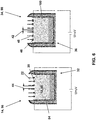
- Fig. 6 is shown as a sectional view of an alternative medical sensor system 10 for detecting at least one feature 12 in at least one animal and / or human body with at least one sensor 14 with a receptor layer 28 as a detection system 60.
- the sensor system 10 has two different regions 32, 36, which are provided as the first sensor 14 and as a second sensor 34. These sensors 14, 34 are arranged spatially separated from each other in the same housing 52 (see. Fig. 7a ).
- the first sensor 14 constitutes a measuring sensor 96 and the second sensor 34 a reference sensor 98.
- each sensor 14, 34 has a reservoir 18 which encloses a sample volume 54 or a reference volume 100. Each reservoir 18 is closed with a closure 16.
- the closure 16 is each formed as an electrically controllable organic membrane 20, 46 having an electroactive polymer 74 of polypyrrole and dodecylbenzenesulfonic acid (not shown in detail), wherein the material 28 of the polymer 74 can thus change its redox state.
- the controllable, organic membranes 20, 46 are each applied to a biocompatible carrier structure 30 made of TiO 2 . Furthermore, they have pores 22, 48 whose diameter 24 is reversibly changeable, whereby the controllable organic membranes 20, 46 are reversibly changeable between an open and a closed state of the reservoir 18.
- the reference sensor 98 is used for a reference measurement by means of which a measured value of an analyte measurement of the sensor 14 can be corrected by a background signal.
- a first diameter 42 of the pore 48 of the controllable, organic membrane 46 is set to detect the feature 12 on the controllable, organic membrane 46 of the second sensor 34 and on the controllable, organic membrane 20 of the first sensor 14, a second diameter 44 of the pore 22 of the controllable, organic membrane 20 is set, wherein the first diameter 42 is smaller than the second diameter 44.
- the first diameter 42 is just adjusted so that the feature 12 or the analyte 50 can not penetrate into the reference volume 100 of the sensor 34 and is for example about 5 nm in the measurement of cystatin C and> 1 nm in the measurement of glucose. On the other hand, any smaller molecule that could interfere with analyte 50 can enter.
- the second diameter 44 of the pores 22 of the controllable organic membrane 20 of the first sensor 14 or of the measuring sensor 96 is increased just as far, for example, to approximately 10 nm for the measurement of cystatin C or, for example, to 1 nm in the measurement of glucose, that the analyte 50 can enter the sample volume 54 to be determined.
- the sensors 14, 34 differ in their structure in the measuring operation thus only by the respective set diameter 42, 44 of the pores 22, 48 of the controllable, organic membranes 20, 46.
- This can be achieved by applying different voltages, for example 1 V to the controllable , organic membrane 20 of the first sensor 14 and a voltage of 1.5 V on the controllable, organic membrane 46 of the second sensor 34 take place.
- the diameter at constant applied voltage (for example, 2 V) can be made by the duration of the applied voltage. Typical values are 4 minutes for the reference measurement and 5 minutes for the analyte measurement.
- the sensors 14, 34, the controllable, organic membranes 20, 46 and the support structure 30 are connected to the housing 52 so that a mass transfer is possible only via the pore membranes and not via connection points of the components
- controllable, organic membranes 20, 46 as a membrane with two independently controllable parts.
- FIG Fig. 7b Several sensor systems 10, 10 'can be combined in a medical sensor array 38, as shown in FIG Fig. 7b In this case, after use of a first sensor system 10 or after reaching the end of a lifetime of the first sensor system 10, a second sensor system 10 'can be activated.
- the sensor system 10 (FIG. Fig. 7a ) or the sensor array 38 (FIG. Fig. 7b ) can be implanted into the human body by attaching it to a medical implant 40 with an anchoring device, not shown in detail.
Landscapes
- Health & Medical Sciences (AREA)
- Life Sciences & Earth Sciences (AREA)
- Physics & Mathematics (AREA)
- Engineering & Computer Science (AREA)
- Animal Behavior & Ethology (AREA)
- Veterinary Medicine (AREA)
- Biophysics (AREA)
- Biomedical Technology (AREA)
- Heart & Thoracic Surgery (AREA)
- Medical Informatics (AREA)
- Molecular Biology (AREA)
- Surgery (AREA)
- Optics & Photonics (AREA)
- General Health & Medical Sciences (AREA)
- Public Health (AREA)
- Pathology (AREA)
- Chemical & Material Sciences (AREA)
- General Engineering & Computer Science (AREA)
- Chemical Kinetics & Catalysis (AREA)
- Dispersion Chemistry (AREA)
- Mechanical Engineering (AREA)
- General Chemical & Material Sciences (AREA)
- Emergency Medicine (AREA)
- Theoretical Computer Science (AREA)
- Fluid Mechanics (AREA)
- Inorganic Chemistry (AREA)
- Measurement Of The Respiration, Hearing Ability, Form, And Blood Characteristics Of Living Organisms (AREA)
Claims (13)
- Système de capteur (10) médical pour le contrôle d'au moins un analyte (12) dans au moins un corps animal et/ou humain, avec au moins un capteur (14 ; 34) présentant au moins un réservoir (18) avec au moins un système de contrôle (60) pour une mesure de l'analyte (12), et au moins une fermeture (16) du réservoir (18) du capteur (14 ; 34), où la fermeture (16) est conçue sous la forme d'une membrane (20, 46) organique réglable, laquelle présente au moins un pore (22, 48) dont le diamètre (24) peut être modifié de manière réversible,
caractérisé en ce que
le système de capteur est conçu de telle manière que,
soit :- dans une première étape, il effectue une mesure de référence, où un premier diamètre (42) du pore (22) de la membrane (20) organique réglable est réglé de telle façon que l'analyte (12) ne peut pas pénétrer dans un volume échantillon (54) du réservoir (18), et toutes les molécules qui sont plus petites que l'analyte (12) peuvent pénétrer dans le volume échantillon (54), où, lors de la mesure de référence avec le système de contrôle (60), des signaux parasites sont déterminés servant de résultat de la mesure de référence, et- dans une deuxième étape, il effectue une mesure d'analyte, où un deuxième diamètre (44) du pore (22) de la membrane (20) organique réglable est réglé de telle façon que l'analyte (12) peut pénétrer dans le volume échantillon (54), où, lors de la mesure d'analyte avec le système de contrôle (60), l'analyte (12) est mesuré en tant que résultat de mesure de la mesure d'analyte, et- le résultat de mesure de la mesure de référence est déduit sous la forme d'un signal de bruit de fond à partir du résultat de mesure de la mesure d'analyte, ce par quoi le système de capteur détermine une valeur finale de mesure,soit :- il effectue une mesure de référence, où un premier diamètre (42) du pore (48) d'une membrane (46) organique réglable d'un deuxième capteur (34) est réglé de telle manière que l'analyte (12) ne peut pas pénétrer dans un volume de référence (100) d'un réservoir (18) du deuxième capteur (34) et toutes les molécules qui sont plus petites que l'analyte (12) peuvent pénétrer dans le volume de référence (100) du réservoir (18) du deuxième capteur (34), où, lors de la mesure de référence avec le système de contrôle (60), des signaux parasites sont évalués en tant que résultat de mesure de la mesure de référence, et- il effectue une mesure d'analyte, où, sur la membrane (20) organique réglable du premier capteur (14), un deuxième diamètre (44) du pore (22) de la membrane (20) organique réglable est réglé de telle façon que l'analyte (12) peut pénétrer dans un volume échantillon (54) du réservoir (18) du premier capteur (14), où, lors de la mesure avec le système de contrôle (60), l'analyte (12) est déterminé sous la forme d'un résultat de mesure de la mesure d'analyte, et- le résultat de mesure de la mesure de référence est déduit sous forme d'un signal de bruit de fond à partir du résultat de mesure de la mesure d'analyte, ce par quoi le système de capteurs détermine une valeur finale de mesure. - Système de capteur médical selon la revendication 1, caractérisé en ce que la membrane (20) organique réglable peut être modifiée entre un état ouvert et un état fermé du réservoir (18) de manière réversible sans étape intermédiaire ou par étapes.
- Système de capteur médical selon la revendication 1 ou 2, caractérisé en ce que le diamètre (24) de l'au moins un pore (22, 48) de la membrane (20) organique réglable peut être modifié de manière réversible sans étape intermédiaire ou par étapes.
- Système de capteur médical selon l'une des revendications précédentes, caractérisé en ce que la membrane (20) organique réglable présente au moins un matériau (26) dont l'état rédox est modifiable.
- Système de capteur médical selon l'une des revendications précédentes, caractérisé en ce que la membrane (20) organique réglable peut être commandée électriquement.
- Système de capteur médical selon l'une des revendications précédentes, caractérisé en ce qu'au moins le premier capteur (14) présente au moins une couche de récepteur (28).
- Système de capteur médical selon l'une des revendications précédentes, caractérisé par une structure support (30) poreuse pour la membrane (20) organique réglable qui présente au moins du TiO2.
- Système de capteur médical selon l'une des revendications précédentes, caractérisé en ce que la membrane (20) organique réglable est rapportée sur une structure support (30) qui présente une biocompatibilité élevée.
- Système de capteur médical selon l'une des revendications précédentes, caractérisé en ce que le même espace (32) est prévu pour servir de premier capteur (14) et de deuxième capteur (34).
- Système de capteur médical selon l'une des revendications 1 à 8, caractérisé en ce que deux espaces (32, 36) différents sont prévus pour servir de premier capteur (14) et de deuxième capteur (34).
- Ensemble de capteurs (38) médical doté d'au moins deux systèmes de capteurs (10 ; 10') selon l'une des revendications 1 à 10.
- Implant médical (40) doté d'un système de capteur (10) médical selon l'une des revendications 1 à 10 et/ou doté d'un ensemble de capteurs (38) selon la revendication 11.
- Procédé d'exploitation d'un système de capteur (10) médical pour le contrôle d'au moins un analyte (12) dans au moins un corps animal et/ou humain avec au moins un capteur (14 ; 34) présentant au moins un réservoir (18) avec au moins un système de contrôle (60) pour une mesure d'analyte de l'analyte (12), et au moins une fermeture (16) du réservoir (18) du capteur (14 ; 34), où la fermeture (16) est conçue sous forme d'une membrane (20, 46) organique réglable, qui peut être modifiée de manière réversible entre un état ouvert et un état fermé du réservoir (18), caractérisé en ce que
soit :- dans une première étape d'une mesure de référence, un premier diamètre (42) du pore (22) de la membrane (20) organique réglable est réglé de telle façon que l'analyte (12) ne peut pas pénétrer dans un volume échantillon (54) du réservoir (18) et toutes les molécules qui sont plus petites que l'analyte (12) peuvent pénétrer dans le volume échantillon (54), où, lors de la mesure de référence avec le système de contrôle (60), des signaux parasites sont déterminés en tant que résultat de la mesure de référence, et- dans une deuxième étape d'une mesure d'analyte, un deuxième diamètre (44) du pore (22) de la membrane (20) organique réglable est réglé de telle façon que l'analyte (12) peut pénétrer dans le volume échantillon (54), où, lors de la mesure d'analyte avec le système de contrôle (60), l'analyte (12) est mesuré en tant que résultat de mesure de la mesure d'analyte, et- le résultat de mesure de la mesure de référence est déduit sous la forme d'un signal de bruit de fond à partir du résultat de mesure de la mesure d'analyte, ce par quoi le système de capteur détermine une valeur finale de mesure,soit :- lors d'une mesure de référence, un premier diamètre (42) du pore (48) d'une membrane (46) organique réglable d'un deuxième capteur (34) est réglé de telle manière que l'analyte (12) ne peut pas pénétrer dans un volume de référence (100) d'un réservoir (18) du deuxième capteur (34) et toutes les molécules qui sont plus petites que l'analyte (12) peuvent pénétrer dans le volume de référence (100) du réservoir (18) du deuxième capteur (34), où, lors de la mesure de référence avec le système de contrôle (60), des signaux parasites sont évalués en tant que résultat de mesure de la mesure de référence, et- lors d'une mesure d'analyte, sur la membrane (20) organique réglable du premier capteur (14), un deuxième diamètre (44) du pore (22) de la membrane (20) organique réglable est réglé de telle façon que l'analyte (12) peut pénétrer dans un volume échantillon (54) du réservoir (18) du premier capteur (14), où, lors de la mesure avec le système de contrôle (60), l'analyte (12) est déterminé sous forme d'un résultat de mesure de la mesure d'analyte, et- le résultat de mesure de la mesure de référence est déduit sous forme d'un signal de bruit de fond à partir du résultat de mesure de la mesure d'analyte, ce par quoi le système de capteurs détermine une valeur finale de mesure.
Applications Claiming Priority (1)
| Application Number | Priority Date | Filing Date | Title |
|---|---|---|---|
| US39062110P | 2010-10-07 | 2010-10-07 |
Publications (2)
| Publication Number | Publication Date |
|---|---|
| EP2438861A1 EP2438861A1 (fr) | 2012-04-11 |
| EP2438861B1 true EP2438861B1 (fr) | 2018-06-06 |
Family
ID=44719673
Family Applications (1)
| Application Number | Title | Priority Date | Filing Date |
|---|---|---|---|
| EP11183754.8A Not-in-force EP2438861B1 (fr) | 2010-10-07 | 2011-10-04 | Système de capteur médical pour contrôler au moins une caractéristique dans au moins un corps animal et/ou humain |
Country Status (2)
| Country | Link |
|---|---|
| US (2) | US9687182B2 (fr) |
| EP (1) | EP2438861B1 (fr) |
Families Citing this family (9)
| Publication number | Priority date | Publication date | Assignee | Title |
|---|---|---|---|---|
| US9444030B2 (en) * | 2013-05-10 | 2016-09-13 | Wisconsin Alumni Research Foundation | Nanoporous piezoelectric polymer films for mechanical energy harvesting |
| GB2520921A (en) * | 2013-10-14 | 2015-06-10 | Phillipa Kay Scott | Protein monitor and correcting device |
| WO2015167347A1 (fr) * | 2014-05-02 | 2015-11-05 | Fisher & Paykel Healthcare Limited | Dispositif d'humidification de gaz |
| US10629800B2 (en) | 2016-08-05 | 2020-04-21 | Wisconsin Alumni Research Foundation | Flexible compact nanogenerators based on mechanoradical-forming porous polymer films |
| US11077475B2 (en) * | 2017-05-23 | 2021-08-03 | International Business Machines Corporation | Neuro-chemical sensor with inhibition of fouling on nano-electrode |
| US10583282B2 (en) | 2017-11-13 | 2020-03-10 | International Business Machines Corporation | Neuro-stem cell stimulation and growth enhancement with implantable nanodevice |
| US11395930B2 (en) | 2018-12-12 | 2022-07-26 | Lucas J. Myslinski | Device, method and system for implementing a physical area network for detecting effects of the sun |
| US11627915B2 (en) | 2018-12-12 | 2023-04-18 | Lucas J. Myslinski | Device, method and system for implementing a physical area network for detecting head injuries |
| US10265017B1 (en) | 2018-12-12 | 2019-04-23 | Lucas J. Myslinski | Device, method and system for implementing a physical area network for cancer immunotherapy |
Citations (2)
| Publication number | Priority date | Publication date | Assignee | Title |
|---|---|---|---|---|
| US20060004272A1 (en) * | 2003-11-13 | 2006-01-05 | Rajiv Shah | Long term analyte sensor array |
| US20080115361A1 (en) * | 2000-03-02 | 2008-05-22 | Microchips, Inc. | Method for Making Reservoir-Based Sensor Device |
Family Cites Families (16)
| Publication number | Priority date | Publication date | Assignee | Title |
|---|---|---|---|---|
| US5290240A (en) | 1993-02-03 | 1994-03-01 | Pharmetrix Corporation | Electrochemical controlled dispensing assembly and method for selective and controlled delivery of a dispensing fluid |
| DE19853286B4 (de) * | 1998-11-19 | 2005-03-03 | Gesellschaft für Schwerionenforschung mbH | Verfahren zum Steuern eines chemischen Ventiles |
| DE60031248T2 (de) * | 1999-02-18 | 2007-05-24 | Biovalve Technologies, Inc., North Grafton | Elektroaktive pore |
| ATE290364T1 (de) | 1999-08-18 | 2005-03-15 | Microchips Inc | Thermisch aktivierbarer microchip als abgabevorrichtung für chemikalien |
| WO2001026708A1 (fr) | 1999-10-12 | 2001-04-19 | The Ohio State University | Valve polymere reactive, dispositifs de distribution et procedes d'utilisation de ces derniers |
| DE10044565B4 (de) | 2000-09-08 | 2005-06-30 | Gesellschaft für Schwerionenforschung mbH | Elektrolytische Zelle, deren Verwendung und Verfahren zum Ätzen einer in der Zelle eingespannten Membran sowie Verfahren zum Schalten einer geätzten, in der Zelle eingespannten Membran von Durchgang auf Sperrung und umgekehrt |
| JP5107041B2 (ja) * | 2004-09-01 | 2012-12-26 | マイクロチップス・インコーポレーテッド | レザバ内容物の制御された放出または曝露のための、マルチキャップレザバデバイス |
| EP1890802A2 (fr) * | 2005-05-25 | 2008-02-27 | Velocys, Inc. | Support destine a etre utilise dans le traitement a l'aide de microcanaux |
| US8273075B2 (en) | 2005-12-13 | 2012-09-25 | The Invention Science Fund I, Llc | Osmotic pump with remotely controlled osmotic flow rate |
| DE102006025344A1 (de) * | 2006-05-31 | 2007-12-06 | MAX-PLANCK-Gesellschaft zur Förderung der Wissenschaften e.V. | Anordnung für eine biologisch funktionelle Membran, Sensoranordnung, Filteranordnung sowie deren Verwendungen |
| WO2008012725A2 (fr) | 2006-07-27 | 2008-01-31 | Koninklijke Philips Electronics N.V. | Système d'administration de médicament à membranes thermo-commutables |
| EP2083673B1 (fr) * | 2006-09-29 | 2012-07-04 | Medingo Ltd. | Systeme destine a fournir un liquide par detection electrochimique de niveaux de concentration d'analyte |
| WO2008095940A1 (fr) | 2007-02-05 | 2008-08-14 | Dublin City University | Appareil et procédé d'analyse d'écoulement |
| EP2157907B1 (fr) | 2007-06-07 | 2013-03-27 | MicroCHIPS, Inc. | Biocapteurs et réseaux électrochimiques |
| US8999378B2 (en) * | 2008-09-24 | 2015-04-07 | President And Fellows Of Harvard College | Porous electroactive hydrogels and uses thereof |
| EP2438860A1 (fr) * | 2010-10-07 | 2012-04-11 | BIOTRONIK SE & Co. KG | Système de détection médical |
-
2011
- 2011-09-29 US US13/248,095 patent/US9687182B2/en not_active Expired - Fee Related
- 2011-10-04 EP EP11183754.8A patent/EP2438861B1/fr not_active Not-in-force
-
2017
- 2017-06-23 US US15/631,823 patent/US20170354360A1/en not_active Abandoned
Patent Citations (2)
| Publication number | Priority date | Publication date | Assignee | Title |
|---|---|---|---|---|
| US20080115361A1 (en) * | 2000-03-02 | 2008-05-22 | Microchips, Inc. | Method for Making Reservoir-Based Sensor Device |
| US20060004272A1 (en) * | 2003-11-13 | 2006-01-05 | Rajiv Shah | Long term analyte sensor array |
Also Published As
| Publication number | Publication date |
|---|---|
| EP2438861A1 (fr) | 2012-04-11 |
| US20120088994A1 (en) | 2012-04-12 |
| US20170354360A1 (en) | 2017-12-14 |
| US9687182B2 (en) | 2017-06-27 |
Similar Documents
| Publication | Publication Date | Title |
|---|---|---|
| EP2438861B1 (fr) | Système de capteur médical pour contrôler au moins une caractéristique dans au moins un corps animal et/ou humain | |
| EP2438860A1 (fr) | Système de détection médical | |
| EP1733676B1 (fr) | Système de capteur, disposition et méthode pour surveiller un composé, en particulier le glucose dans le tissu du corps. | |
| DE2817363C2 (de) | Verfahren zur Konzentrationsbestimmung von Zucker und dafür geeigneter elektrokatalytischer Zuckersensor | |
| EP1785086B1 (fr) | Système implantable d'électrodes et dispositif de mesure de la concentration d'un analyte dans un corps humain ou animal | |
| US8936794B2 (en) | Conducting polymer nanotube actuators for precisely controlled release of medicine and bioactive molecules | |
| Kim et al. | Conducting polymers on hydrogel-coated neural electrode provide sensitive neural recordings in auditory cortex | |
| EP0170998B1 (fr) | Procédé pour la détection électrochimique de la concentration en oxygène | |
| EP2163190A1 (fr) | Système d'électrodes pour la mesure d'une concentration d'analyte in vivo | |
| DE69837709T2 (de) | Vorrichtung und verfahren zur bestimmung des analytpegels | |
| DE60008517T2 (de) | Derivatisiertes poröses silicium | |
| EP3282250B1 (fr) | Capteur électrochimique destiné à la détermination d'une concentration analytique | |
| EP2164384A2 (fr) | Implant d'hydrogel pour la détection par capteurs de métabolites dans des tissus corporels | |
| DE102004062394A1 (de) | Intravenöse Herzschrittmacherelektrode | |
| EP1123040A1 (fr) | Systeme de capteur a invasion minimale | |
| DE19540456C2 (de) | Verfahren zur Messung der Glukosekonzentration in einer Flüssigkeit und Verwendung des Verfahrens | |
| DE4426694C2 (de) | Vorrichtung zur Langzeitbestimmung des Gehaltes von mindestens einer Substanz in Körperflüssigkeiten | |
| DE102011081472A1 (de) | Medizinisches Sensorsystem | |
| DE102008010876B4 (de) | Mikrosystem zur gesteuerten Wirkstofffreisetzung | |
| EP2452624A1 (fr) | Article théranostique implantable | |
| Pfau et al. | In Situ Measurement of Stimulus Induced pH Changes Using ThinFilm Embedded IrOx pH Electrodes | |
| DE4331934C1 (de) | Implantierbare Biosensor- und Pharmakaapplikationsanordnung und Verfahren zur Sterilisation | |
| DE102014221587A1 (de) | Verfahren zum Beschichten eines medizinischen Implantats | |
| EP2554215A1 (fr) | Procédé et agencement de réactivation d'une capteur chimique implantable | |
| WO2023174485A1 (fr) | Biocapteur implantable |
Legal Events
| Date | Code | Title | Description |
|---|---|---|---|
| AK | Designated contracting states |
Kind code of ref document: A1 Designated state(s): AL AT BE BG CH CY CZ DE DK EE ES FI FR GB GR HR HU IE IS IT LI LT LU LV MC MK MT NL NO PL PT RO RS SE SI SK SM TR |
|
| AX | Request for extension of the european patent |
Extension state: BA ME |
|
| PUAI | Public reference made under article 153(3) epc to a published international application that has entered the european phase |
Free format text: ORIGINAL CODE: 0009012 |
|
| 17P | Request for examination filed |
Effective date: 20120920 |
|
| RAP1 | Party data changed (applicant data changed or rights of an application transferred) |
Owner name: BIOTRONIK SE & CO. KG |
|
| GRAP | Despatch of communication of intention to grant a patent |
Free format text: ORIGINAL CODE: EPIDOSNIGR1 |
|
| STAA | Information on the status of an ep patent application or granted ep patent |
Free format text: STATUS: GRANT OF PATENT IS INTENDED |
|
| INTG | Intention to grant announced |
Effective date: 20180123 |
|
| GRAS | Grant fee paid |
Free format text: ORIGINAL CODE: EPIDOSNIGR3 |
|
| GRAA | (expected) grant |
Free format text: ORIGINAL CODE: 0009210 |
|
| STAA | Information on the status of an ep patent application or granted ep patent |
Free format text: STATUS: THE PATENT HAS BEEN GRANTED |
|
| AK | Designated contracting states |
Kind code of ref document: B1 Designated state(s): AL AT BE BG CH CY CZ DE DK EE ES FI FR GB GR HR HU IE IS IT LI LT LU LV MC MK MT NL NO PL PT RO RS SE SI SK SM TR |
|
| REG | Reference to a national code |
Ref country code: GB Ref legal event code: FG4D Free format text: NOT ENGLISH |
|
| REG | Reference to a national code |
Ref country code: CH Ref legal event code: EP Ref country code: AT Ref legal event code: REF Ref document number: 1005161 Country of ref document: AT Kind code of ref document: T Effective date: 20180615 |
|
| REG | Reference to a national code |
Ref country code: IE Ref legal event code: FG4D Free format text: LANGUAGE OF EP DOCUMENT: GERMAN |
|
| REG | Reference to a national code |
Ref country code: DE Ref legal event code: R096 Ref document number: 502011014286 Country of ref document: DE |
|
| REG | Reference to a national code |
Ref country code: NL Ref legal event code: MP Effective date: 20180606 |
|
| REG | Reference to a national code |
Ref country code: LT Ref legal event code: MG4D |
|
| PG25 | Lapsed in a contracting state [announced via postgrant information from national office to epo] |
Ref country code: SE Free format text: LAPSE BECAUSE OF FAILURE TO SUBMIT A TRANSLATION OF THE DESCRIPTION OR TO PAY THE FEE WITHIN THE PRESCRIBED TIME-LIMIT Effective date: 20180606 Ref country code: BG Free format text: LAPSE BECAUSE OF FAILURE TO SUBMIT A TRANSLATION OF THE DESCRIPTION OR TO PAY THE FEE WITHIN THE PRESCRIBED TIME-LIMIT Effective date: 20180906 Ref country code: LT Free format text: LAPSE BECAUSE OF FAILURE TO SUBMIT A TRANSLATION OF THE DESCRIPTION OR TO PAY THE FEE WITHIN THE PRESCRIBED TIME-LIMIT Effective date: 20180606 Ref country code: FI Free format text: LAPSE BECAUSE OF FAILURE TO SUBMIT A TRANSLATION OF THE DESCRIPTION OR TO PAY THE FEE WITHIN THE PRESCRIBED TIME-LIMIT Effective date: 20180606 Ref country code: CY Free format text: LAPSE BECAUSE OF FAILURE TO SUBMIT A TRANSLATION OF THE DESCRIPTION OR TO PAY THE FEE WITHIN THE PRESCRIBED TIME-LIMIT Effective date: 20180606 Ref country code: NO Free format text: LAPSE BECAUSE OF FAILURE TO SUBMIT A TRANSLATION OF THE DESCRIPTION OR TO PAY THE FEE WITHIN THE PRESCRIBED TIME-LIMIT Effective date: 20180906 Ref country code: ES Free format text: LAPSE BECAUSE OF FAILURE TO SUBMIT A TRANSLATION OF THE DESCRIPTION OR TO PAY THE FEE WITHIN THE PRESCRIBED TIME-LIMIT Effective date: 20180606 |
|
| PG25 | Lapsed in a contracting state [announced via postgrant information from national office to epo] |
Ref country code: GR Free format text: LAPSE BECAUSE OF FAILURE TO SUBMIT A TRANSLATION OF THE DESCRIPTION OR TO PAY THE FEE WITHIN THE PRESCRIBED TIME-LIMIT Effective date: 20180907 Ref country code: HR Free format text: LAPSE BECAUSE OF FAILURE TO SUBMIT A TRANSLATION OF THE DESCRIPTION OR TO PAY THE FEE WITHIN THE PRESCRIBED TIME-LIMIT Effective date: 20180606 Ref country code: LV Free format text: LAPSE BECAUSE OF FAILURE TO SUBMIT A TRANSLATION OF THE DESCRIPTION OR TO PAY THE FEE WITHIN THE PRESCRIBED TIME-LIMIT Effective date: 20180606 Ref country code: RS Free format text: LAPSE BECAUSE OF FAILURE TO SUBMIT A TRANSLATION OF THE DESCRIPTION OR TO PAY THE FEE WITHIN THE PRESCRIBED TIME-LIMIT Effective date: 20180606 |
|
| PG25 | Lapsed in a contracting state [announced via postgrant information from national office to epo] |
Ref country code: NL Free format text: LAPSE BECAUSE OF FAILURE TO SUBMIT A TRANSLATION OF THE DESCRIPTION OR TO PAY THE FEE WITHIN THE PRESCRIBED TIME-LIMIT Effective date: 20180606 |
|
| PG25 | Lapsed in a contracting state [announced via postgrant information from national office to epo] |
Ref country code: RO Free format text: LAPSE BECAUSE OF FAILURE TO SUBMIT A TRANSLATION OF THE DESCRIPTION OR TO PAY THE FEE WITHIN THE PRESCRIBED TIME-LIMIT Effective date: 20180606 Ref country code: CZ Free format text: LAPSE BECAUSE OF FAILURE TO SUBMIT A TRANSLATION OF THE DESCRIPTION OR TO PAY THE FEE WITHIN THE PRESCRIBED TIME-LIMIT Effective date: 20180606 Ref country code: PL Free format text: LAPSE BECAUSE OF FAILURE TO SUBMIT A TRANSLATION OF THE DESCRIPTION OR TO PAY THE FEE WITHIN THE PRESCRIBED TIME-LIMIT Effective date: 20180606 Ref country code: EE Free format text: LAPSE BECAUSE OF FAILURE TO SUBMIT A TRANSLATION OF THE DESCRIPTION OR TO PAY THE FEE WITHIN THE PRESCRIBED TIME-LIMIT Effective date: 20180606 Ref country code: IS Free format text: LAPSE BECAUSE OF FAILURE TO SUBMIT A TRANSLATION OF THE DESCRIPTION OR TO PAY THE FEE WITHIN THE PRESCRIBED TIME-LIMIT Effective date: 20181006 Ref country code: SK Free format text: LAPSE BECAUSE OF FAILURE TO SUBMIT A TRANSLATION OF THE DESCRIPTION OR TO PAY THE FEE WITHIN THE PRESCRIBED TIME-LIMIT Effective date: 20180606 |
|
| PG25 | Lapsed in a contracting state [announced via postgrant information from national office to epo] |
Ref country code: IT Free format text: LAPSE BECAUSE OF FAILURE TO SUBMIT A TRANSLATION OF THE DESCRIPTION OR TO PAY THE FEE WITHIN THE PRESCRIBED TIME-LIMIT Effective date: 20180606 Ref country code: SM Free format text: LAPSE BECAUSE OF FAILURE TO SUBMIT A TRANSLATION OF THE DESCRIPTION OR TO PAY THE FEE WITHIN THE PRESCRIBED TIME-LIMIT Effective date: 20180606 |
|
| REG | Reference to a national code |
Ref country code: DE Ref legal event code: R097 Ref document number: 502011014286 Country of ref document: DE |
|
| PLBE | No opposition filed within time limit |
Free format text: ORIGINAL CODE: 0009261 |
|
| STAA | Information on the status of an ep patent application or granted ep patent |
Free format text: STATUS: NO OPPOSITION FILED WITHIN TIME LIMIT |
|
| 26N | No opposition filed |
Effective date: 20190307 |
|
| PG25 | Lapsed in a contracting state [announced via postgrant information from national office to epo] |
Ref country code: DK Free format text: LAPSE BECAUSE OF FAILURE TO SUBMIT A TRANSLATION OF THE DESCRIPTION OR TO PAY THE FEE WITHIN THE PRESCRIBED TIME-LIMIT Effective date: 20180606 Ref country code: SI Free format text: LAPSE BECAUSE OF FAILURE TO SUBMIT A TRANSLATION OF THE DESCRIPTION OR TO PAY THE FEE WITHIN THE PRESCRIBED TIME-LIMIT Effective date: 20180606 |
|
| GBPC | Gb: european patent ceased through non-payment of renewal fee |
Effective date: 20181004 |
|
| REG | Reference to a national code |
Ref country code: BE Ref legal event code: MM Effective date: 20181031 |
|
| PG25 | Lapsed in a contracting state [announced via postgrant information from national office to epo] |
Ref country code: LU Free format text: LAPSE BECAUSE OF NON-PAYMENT OF DUE FEES Effective date: 20181004 Ref country code: MC Free format text: LAPSE BECAUSE OF FAILURE TO SUBMIT A TRANSLATION OF THE DESCRIPTION OR TO PAY THE FEE WITHIN THE PRESCRIBED TIME-LIMIT Effective date: 20180606 |
|
| PG25 | Lapsed in a contracting state [announced via postgrant information from national office to epo] |
Ref country code: FR Free format text: LAPSE BECAUSE OF NON-PAYMENT OF DUE FEES Effective date: 20181031 Ref country code: BE Free format text: LAPSE BECAUSE OF NON-PAYMENT OF DUE FEES Effective date: 20181031 |
|
| PG25 | Lapsed in a contracting state [announced via postgrant information from national office to epo] |
Ref country code: GB Free format text: LAPSE BECAUSE OF NON-PAYMENT OF DUE FEES Effective date: 20181004 |
|
| PG25 | Lapsed in a contracting state [announced via postgrant information from national office to epo] |
Ref country code: AL Free format text: LAPSE BECAUSE OF FAILURE TO SUBMIT A TRANSLATION OF THE DESCRIPTION OR TO PAY THE FEE WITHIN THE PRESCRIBED TIME-LIMIT Effective date: 20180606 |
|
| REG | Reference to a national code |
Ref country code: AT Ref legal event code: MM01 Ref document number: 1005161 Country of ref document: AT Kind code of ref document: T Effective date: 20181004 |
|
| PG25 | Lapsed in a contracting state [announced via postgrant information from national office to epo] |
Ref country code: MT Free format text: LAPSE BECAUSE OF FAILURE TO SUBMIT A TRANSLATION OF THE DESCRIPTION OR TO PAY THE FEE WITHIN THE PRESCRIBED TIME-LIMIT Effective date: 20180606 Ref country code: AT Free format text: LAPSE BECAUSE OF NON-PAYMENT OF DUE FEES Effective date: 20181004 |
|
| PG25 | Lapsed in a contracting state [announced via postgrant information from national office to epo] |
Ref country code: TR Free format text: LAPSE BECAUSE OF FAILURE TO SUBMIT A TRANSLATION OF THE DESCRIPTION OR TO PAY THE FEE WITHIN THE PRESCRIBED TIME-LIMIT Effective date: 20180606 |
|
| PG25 | Lapsed in a contracting state [announced via postgrant information from national office to epo] |
Ref country code: PT Free format text: LAPSE BECAUSE OF FAILURE TO SUBMIT A TRANSLATION OF THE DESCRIPTION OR TO PAY THE FEE WITHIN THE PRESCRIBED TIME-LIMIT Effective date: 20180606 |
|
| PG25 | Lapsed in a contracting state [announced via postgrant information from national office to epo] |
Ref country code: MK Free format text: LAPSE BECAUSE OF NON-PAYMENT OF DUE FEES Effective date: 20180606 Ref country code: HU Free format text: LAPSE BECAUSE OF FAILURE TO SUBMIT A TRANSLATION OF THE DESCRIPTION OR TO PAY THE FEE WITHIN THE PRESCRIBED TIME-LIMIT; INVALID AB INITIO Effective date: 20111004 |
|
| PGFP | Annual fee paid to national office [announced via postgrant information from national office to epo] |
Ref country code: IE Payment date: 20211021 Year of fee payment: 11 Ref country code: DE Payment date: 20211022 Year of fee payment: 11 |
|
| PGFP | Annual fee paid to national office [announced via postgrant information from national office to epo] |
Ref country code: CH Payment date: 20211022 Year of fee payment: 11 |
|
| REG | Reference to a national code |
Ref country code: DE Ref legal event code: R119 Ref document number: 502011014286 Country of ref document: DE |
|
| REG | Reference to a national code |
Ref country code: CH Ref legal event code: PL |
|
| PG25 | Lapsed in a contracting state [announced via postgrant information from national office to epo] |
Ref country code: LI Free format text: LAPSE BECAUSE OF NON-PAYMENT OF DUE FEES Effective date: 20221031 Ref country code: DE Free format text: LAPSE BECAUSE OF NON-PAYMENT OF DUE FEES Effective date: 20230503 Ref country code: CH Free format text: LAPSE BECAUSE OF NON-PAYMENT OF DUE FEES Effective date: 20221031 |
|
| PG25 | Lapsed in a contracting state [announced via postgrant information from national office to epo] |
Ref country code: IE Free format text: LAPSE BECAUSE OF NON-PAYMENT OF DUE FEES Effective date: 20221004 |