EP2441104B1 - Matrice support pour connecteur d'éléments de batterie - Google Patents
Matrice support pour connecteur d'éléments de batterie Download PDFInfo
- Publication number
- EP2441104B1 EP2441104B1 EP10722120.2A EP10722120A EP2441104B1 EP 2441104 B1 EP2441104 B1 EP 2441104B1 EP 10722120 A EP10722120 A EP 10722120A EP 2441104 B1 EP2441104 B1 EP 2441104B1
- Authority
- EP
- European Patent Office
- Prior art keywords
- receiver
- battery cell
- carrier
- battery
- batteries
- Prior art date
- Legal status (The legal status is an assumption and is not a legal conclusion. Google has not performed a legal analysis and makes no representation as to the accuracy of the status listed.)
- Not-in-force
Links
- 239000011159 matrix material Substances 0.000 title claims description 49
- 238000004519 manufacturing process Methods 0.000 claims description 9
- 210000001331 nose Anatomy 0.000 claims description 4
- 238000003825 pressing Methods 0.000 claims description 3
- 239000004952 Polyamide Substances 0.000 claims description 2
- 229920002647 polyamide Polymers 0.000 claims description 2
- 239000012811 non-conductive material Substances 0.000 claims 1
- 238000003466 welding Methods 0.000 description 28
- 229910052751 metal Inorganic materials 0.000 description 27
- 239000002184 metal Substances 0.000 description 27
- 239000000463 material Substances 0.000 description 17
- 238000000034 method Methods 0.000 description 17
- 150000002739 metals Chemical class 0.000 description 14
- 229910052782 aluminium Inorganic materials 0.000 description 11
- XAGFODPZIPBFFR-UHFFFAOYSA-N aluminium Chemical compound [Al] XAGFODPZIPBFFR-UHFFFAOYSA-N 0.000 description 11
- PXHVJJICTQNCMI-UHFFFAOYSA-N Nickel Chemical compound [Ni] PXHVJJICTQNCMI-UHFFFAOYSA-N 0.000 description 10
- RYGMFSIKBFXOCR-UHFFFAOYSA-N Copper Chemical compound [Cu] RYGMFSIKBFXOCR-UHFFFAOYSA-N 0.000 description 9
- 239000000956 alloy Substances 0.000 description 9
- 229910045601 alloy Inorganic materials 0.000 description 9
- 239000010949 copper Substances 0.000 description 9
- 229910052802 copper Inorganic materials 0.000 description 9
- XEEYBQQBJWHFJM-UHFFFAOYSA-N Iron Chemical compound [Fe] XEEYBQQBJWHFJM-UHFFFAOYSA-N 0.000 description 8
- 229910000831 Steel Inorganic materials 0.000 description 8
- 239000004020 conductor Substances 0.000 description 8
- 239000010959 steel Substances 0.000 description 8
- BQCADISMDOOEFD-UHFFFAOYSA-N Silver Chemical compound [Ag] BQCADISMDOOEFD-UHFFFAOYSA-N 0.000 description 7
- 229910052709 silver Inorganic materials 0.000 description 7
- 239000004332 silver Substances 0.000 description 7
- ATJFFYVFTNAWJD-UHFFFAOYSA-N Tin Chemical compound [Sn] ATJFFYVFTNAWJD-UHFFFAOYSA-N 0.000 description 6
- HCHKCACWOHOZIP-UHFFFAOYSA-N Zinc Chemical compound [Zn] HCHKCACWOHOZIP-UHFFFAOYSA-N 0.000 description 6
- PCHJSUWPFVWCPO-UHFFFAOYSA-N gold Chemical compound [Au] PCHJSUWPFVWCPO-UHFFFAOYSA-N 0.000 description 6
- 229910052737 gold Inorganic materials 0.000 description 6
- 239000010931 gold Substances 0.000 description 6
- 239000011135 tin Substances 0.000 description 6
- 229910052718 tin Inorganic materials 0.000 description 6
- 229910052725 zinc Inorganic materials 0.000 description 6
- 239000011701 zinc Substances 0.000 description 6
- 229910052759 nickel Inorganic materials 0.000 description 5
- HBBGRARXTFLTSG-UHFFFAOYSA-N Lithium ion Chemical compound [Li+] HBBGRARXTFLTSG-UHFFFAOYSA-N 0.000 description 4
- 238000004146 energy storage Methods 0.000 description 4
- 239000011888 foil Substances 0.000 description 4
- 229910052742 iron Inorganic materials 0.000 description 4
- 229910001416 lithium ion Inorganic materials 0.000 description 4
- 230000002093 peripheral effect Effects 0.000 description 3
- 239000004033 plastic Substances 0.000 description 3
- 239000011343 solid material Substances 0.000 description 3
- 239000000126 substance Substances 0.000 description 3
- 230000007704 transition Effects 0.000 description 3
- 238000013022 venting Methods 0.000 description 3
- 239000011248 coating agent Substances 0.000 description 2
- 238000000576 coating method Methods 0.000 description 2
- 238000010276 construction Methods 0.000 description 2
- 238000005520 cutting process Methods 0.000 description 2
- 230000020169 heat generation Effects 0.000 description 2
- 229910052987 metal hydride Inorganic materials 0.000 description 2
- 238000000465 moulding Methods 0.000 description 2
- 238000009423 ventilation Methods 0.000 description 2
- WHXSMMKQMYFTQS-UHFFFAOYSA-N Lithium Chemical compound [Li] WHXSMMKQMYFTQS-UHFFFAOYSA-N 0.000 description 1
- 230000032683 aging Effects 0.000 description 1
- 230000006835 compression Effects 0.000 description 1
- 238000007906 compression Methods 0.000 description 1
- 238000010438 heat treatment Methods 0.000 description 1
- 238000009776 industrial production Methods 0.000 description 1
- 238000002347 injection Methods 0.000 description 1
- 239000007924 injection Substances 0.000 description 1
- 238000009434 installation Methods 0.000 description 1
- 238000003698 laser cutting Methods 0.000 description 1
- 229910052744 lithium Inorganic materials 0.000 description 1
- 230000003446 memory effect Effects 0.000 description 1
- 150000004681 metal hydrides Chemical class 0.000 description 1
- 238000012544 monitoring process Methods 0.000 description 1
- 229920000642 polymer Polymers 0.000 description 1
- 238000010079 rubber tapping Methods 0.000 description 1
- 238000003756 stirring Methods 0.000 description 1
- 238000003860 storage Methods 0.000 description 1
- XLYOFNOQVPJJNP-UHFFFAOYSA-N water Substances O XLYOFNOQVPJJNP-UHFFFAOYSA-N 0.000 description 1
Images




Classifications
-
- H—ELECTRICITY
- H01—ELECTRIC ELEMENTS
- H01M—PROCESSES OR MEANS, e.g. BATTERIES, FOR THE DIRECT CONVERSION OF CHEMICAL ENERGY INTO ELECTRICAL ENERGY
- H01M50/00—Constructional details or processes of manufacture of the non-active parts of electrochemical cells other than fuel cells, e.g. hybrid cells
- H01M50/50—Current conducting connections for cells or batteries
- H01M50/528—Fixed electrical connections, i.e. not intended for disconnection
-
- H—ELECTRICITY
- H01—ELECTRIC ELEMENTS
- H01M—PROCESSES OR MEANS, e.g. BATTERIES, FOR THE DIRECT CONVERSION OF CHEMICAL ENERGY INTO ELECTRICAL ENERGY
- H01M50/00—Constructional details or processes of manufacture of the non-active parts of electrochemical cells other than fuel cells, e.g. hybrid cells
- H01M50/50—Current conducting connections for cells or batteries
- H01M50/571—Methods or arrangements for affording protection against corrosion; Selection of materials therefor
-
- H—ELECTRICITY
- H01—ELECTRIC ELEMENTS
- H01M—PROCESSES OR MEANS, e.g. BATTERIES, FOR THE DIRECT CONVERSION OF CHEMICAL ENERGY INTO ELECTRICAL ENERGY
- H01M50/00—Constructional details or processes of manufacture of the non-active parts of electrochemical cells other than fuel cells, e.g. hybrid cells
- H01M50/50—Current conducting connections for cells or batteries
- H01M50/502—Interconnectors for connecting terminals of adjacent batteries; Interconnectors for connecting cells outside a battery casing
- H01M50/514—Methods for interconnecting adjacent batteries or cells
- H01M50/516—Methods for interconnecting adjacent batteries or cells by welding, soldering or brazing
-
- H—ELECTRICITY
- H01—ELECTRIC ELEMENTS
- H01M—PROCESSES OR MEANS, e.g. BATTERIES, FOR THE DIRECT CONVERSION OF CHEMICAL ENERGY INTO ELECTRICAL ENERGY
- H01M50/00—Constructional details or processes of manufacture of the non-active parts of electrochemical cells other than fuel cells, e.g. hybrid cells
- H01M50/50—Current conducting connections for cells or batteries
- H01M50/502—Interconnectors for connecting terminals of adjacent batteries; Interconnectors for connecting cells outside a battery casing
- H01M50/519—Interconnectors for connecting terminals of adjacent batteries; Interconnectors for connecting cells outside a battery casing comprising printed circuit boards [PCB]
-
- H—ELECTRICITY
- H01—ELECTRIC ELEMENTS
- H01M—PROCESSES OR MEANS, e.g. BATTERIES, FOR THE DIRECT CONVERSION OF CHEMICAL ENERGY INTO ELECTRICAL ENERGY
- H01M50/00—Constructional details or processes of manufacture of the non-active parts of electrochemical cells other than fuel cells, e.g. hybrid cells
- H01M50/50—Current conducting connections for cells or batteries
- H01M50/502—Interconnectors for connecting terminals of adjacent batteries; Interconnectors for connecting cells outside a battery casing
- H01M50/521—Interconnectors for connecting terminals of adjacent batteries; Interconnectors for connecting cells outside a battery casing characterised by the material
- H01M50/524—Organic material
-
- H—ELECTRICITY
- H01—ELECTRIC ELEMENTS
- H01M—PROCESSES OR MEANS, e.g. BATTERIES, FOR THE DIRECT CONVERSION OF CHEMICAL ENERGY INTO ELECTRICAL ENERGY
- H01M50/00—Constructional details or processes of manufacture of the non-active parts of electrochemical cells other than fuel cells, e.g. hybrid cells
- H01M50/50—Current conducting connections for cells or batteries
- H01M50/543—Terminals
- H01M50/547—Terminals characterised by the disposition of the terminals on the cells
- H01M50/548—Terminals characterised by the disposition of the terminals on the cells on opposite sides of the cell
-
- H—ELECTRICITY
- H01—ELECTRIC ELEMENTS
- H01M—PROCESSES OR MEANS, e.g. BATTERIES, FOR THE DIRECT CONVERSION OF CHEMICAL ENERGY INTO ELECTRICAL ENERGY
- H01M10/00—Secondary cells; Manufacture thereof
- H01M10/05—Accumulators with non-aqueous electrolyte
- H01M10/052—Li-accumulators
-
- Y—GENERAL TAGGING OF NEW TECHNOLOGICAL DEVELOPMENTS; GENERAL TAGGING OF CROSS-SECTIONAL TECHNOLOGIES SPANNING OVER SEVERAL SECTIONS OF THE IPC; TECHNICAL SUBJECTS COVERED BY FORMER USPC CROSS-REFERENCE ART COLLECTIONS [XRACs] AND DIGESTS
- Y02—TECHNOLOGIES OR APPLICATIONS FOR MITIGATION OR ADAPTATION AGAINST CLIMATE CHANGE
- Y02E—REDUCTION OF GREENHOUSE GAS [GHG] EMISSIONS, RELATED TO ENERGY GENERATION, TRANSMISSION OR DISTRIBUTION
- Y02E60/00—Enabling technologies; Technologies with a potential or indirect contribution to GHG emissions mitigation
- Y02E60/10—Energy storage using batteries
-
- Y—GENERAL TAGGING OF NEW TECHNOLOGICAL DEVELOPMENTS; GENERAL TAGGING OF CROSS-SECTIONAL TECHNOLOGIES SPANNING OVER SEVERAL SECTIONS OF THE IPC; TECHNICAL SUBJECTS COVERED BY FORMER USPC CROSS-REFERENCE ART COLLECTIONS [XRACs] AND DIGESTS
- Y10—TECHNICAL SUBJECTS COVERED BY FORMER USPC
- Y10T—TECHNICAL SUBJECTS COVERED BY FORMER US CLASSIFICATION
- Y10T29/00—Metal working
- Y10T29/49—Method of mechanical manufacture
- Y10T29/49002—Electrical device making
- Y10T29/49108—Electric battery cell making
Definitions
- the subject matter relates to a carrier matrix for battery cell connectors. Moreover, the subject matter relates to a battery cell module having at least two carrier matrices and a set of batteries and to a method for manufacturing a battery cell module.
- Batteries especially lithium-ion batteries, but also metal-hydride batteries, such as nickel-metal hydride batteries, or lithium polymer batteries or other chemical energy storage, are gaining in importance in the automotive industry.
- metal-hydride batteries such as nickel-metal hydride batteries, or lithium polymer batteries or other chemical energy storage
- the storage of electrical energy is of immense importance for future automobile construction.
- novel batteries such as lithium-ion batteries
- these accumulators store a large amount of energy in a small volume and, on the other hand, such batteries are only conditionally subject to an aging process. In particular, a "memory effect" does not occur with this. As a result, a plurality of charging cycles can take place, so that the life of the batteries substantially corresponds to that of a vehicle.
- batteries provide only low voltages between one and several tens of volts. These low voltages are far from sufficient to drive an electric motor of an electric vehicle.
- most batteries provide electric charge only between 1000 and 5000 mAh, which is not enough to power a vehicle for a sufficient amount of time.
- batteries are connected to so-called battery packs.
- a plurality of individual batteries (cells) can be connected in series with each other, whereby the output voltage of the battery pack multiplied according to the number of series-connected batteries.
- battery packs are used with a total of 96 batteries.
- eight modules with twelve batteries each are interconnected.
- six modules arranged vertically one above the other in a column are interconnected in series with each module.
- Such a column is connected in series with a second column of the same module arranged horizontally next to it in series.
- a total output voltage of 4V by 12 batteries will result in 48V per module and per 384V battery pack.
- the problem with the construction of a module is the contacting of two batteries to be switched in series at their respective opposite polarity poles.
- the battery pole of a first polarity of a different metal due to the chemical energy storage in the batteries, the battery pole of a first polarity of a different metal than the battery pole of a second polarity of the same battery.
- lithium-ion batteries have a battery pole made of steel and a second battery pole Aluminum.
- other combinations of metals are also common.
- the poles of different polarity are made of different metals.
- the distance between two opposite poles is subject to tolerances. That is, if two batteries are arranged side by side substantially in a plane, the poles may not be exactly coplanar. Also often the positive pole of a battery is formed by a projection on the one battery cover and the negative pole by a return on the opposite lid of the battery. If one now wants to connect a positive pole of a first battery to a negative pole of a second battery, then on the one hand the use of the different metals has to be taken into account and on the other hand the tolerance-related deviation of the poles from each other.
- the current flow through the contacts is very high, as a variety of batteries are connected in series, which provide several amperes, possibly even several tens of amperes or several hundred amps in the load case. These high currents must flow through all the batteries and the respective battery cell connectors.
- the electrical contacts of the battery poles to the battery cell connectors must therefore be low in order to minimize the heat loss in the connectors. Therefore, a clean electrical contact must be ensured over the entire life of the battery module. To ensure this, the battery cell connectors are regularly connected to the battery poles materially.
- connection means for electrically connecting a plurality of battery cells which comprises a different line sections having leadframe.
- a disadvantage of the described lead frame is that the different line sections embedded in the plastic frame and the plastic frame is thus no longer quickly and mechanically equipped with line sections.
- a battery module comprising a carrier matrix.
- the carrier matrix serves to receive partial battery cell connectors, which in turn are provided for interconnecting the battery cells.
- a disadvantage of the described carrier matrix is that the partial battery cell connectors arranged in the carrier matrix are each connected to only one battery.
- the objective carrier matrix it is possible to connect at least three batteries arranged in one column and two columns arranged next to one another.
- the battery cell connectors can be accommodated for connecting two batteries arranged one above the other.
- the respective last batteries in a column can be connected by means of a battery cell connector which is arranged in a horizontal receptacle.
- the horizontal shot and the vertical shot can be objectively orthogonal to each other.
- horizontal and vertical the spatial orientation of the Shoot each other to express. It is not mandatory that the vertical mount is in the perpendicular and that the horizontal mount is horizontal. Rather, it is objective that the horizontal image is substantially normal to the vertical recording.
- a circuit board receptacle for a circuit board is formed in the support between the columns.
- This circuit board receptacle can physically accommodate a printed circuit board, branch off from the taps, which is connectable to connection areas each of a battery cell connector. About these taps, the temperature of the respective battery cell connector can be measured on the circuit board.
- the horizontal receptacle and / or the vertical receptacle are formed for flush-mounting a battery cell connector. In this case, the battery cell connector, at least on the side facing the battery, can be flush with the side of the carrier facing the battery.
- the horizontal receptacle and / or the vertical receptacle are shaped in such a way that on a side of the support facing a battery, a battery cell connector with a flat piece and a first connection part is flush with the side of the support facing the battery.
- the horizontal receptacle and / or the vertical receptacle have latching lugs for the positive fastening of the battery cell connectors.
- the battery cell connectors it is possible for the battery cell connectors to be inserted into the carrier from the side facing the battery. In this case, the battery cell connectors are "clipped" into the receptacles via the latching lugs.
- the latching noses which can be arranged on the side of the carrier facing the battery, bend outwards, so that the battery cell connectors reach into the receptacles and lock there.
- a carrier can be equipped with battery cell connectors quickly and automatically.
- the latching lugs prevent the battery cell connectors from falling out of the carrier before the integral connection with the battery poles. In addition, after the connection to the battery poles of the carrier due to the locking lugs can only be deducted by the application of the applied forces of the locking lugs of the battery module.
- the horizontal receptacle and / or the vertical receptacle on the side facing away from the locking lugs retaining shoulders have as a counter bearing for receiving the battery cell connector.
- the Battery cell connectors have a first connection part, an offset and a second connection part with a flat piece arranged thereon.
- a retaining shoulder may be provided in the region of the second connecting part such that the area of the second connecting part not covered by the flat piece rests on the retaining shoulder.
- a retaining shoulder may be provided in the region of the connecting part.
- a holding shoulder may be provided for fastening the first connection part.
- the carrier is molded from polyamide.
- a PA6 plastic is used.
- the carrier has recesses between the horizontal receptacle and / or the vertical receptacle and the circuit board receptacle in the region of connecting regions of the battery cell connectors.
- An electrical connection between the printed circuit board and the battery cell connector, in particular the connecting region of the battery cell connector, can take place via these recesses.
- a temperature sensor on the battery cell connector is possible by means of a sensor arranged on the printed circuit board per battery cell connector.
- two horizontally juxtaposed sword holders are arranged on the opposite side of the horizontal holder of the carrier.
- twelve batteries are connected in series by means of two carrier matrices.
- two horizontally juxtaposed contacts are provided at the ends, which are each connected to the poles of their associated batteries. The so tapped voltages can be led out of the surface of the carrier matrix via swords and can be tapped there.
- a plurality of modules can be electrically connected to one another by means of module connectors.
- the sword receptacles have recesses for receiving protruding from the surface of the carrier swords.
- About the swords can be tapped by means of plugs, the voltages applied there.
- two guides are fastened to the carrier on the side facing the batteries.
- the batteries can be brought to the support matrix, for example, with six pieces per column and two columns next to one another as a pallet in one production step.
- guides to the carrier.
- Per Battery cell connectors as described above, a positive pole and a negative pole of the battery are connected in series with each other.
- These two batteries can be guided in the correct position by means of the guides to the battery cell connectors, respectively the first connection part and the flat piece.
- the battery poles can be guided substantially coaxially with the vents of the battery cell connectors and thus can be easily welded by means of a laser.
- the guides When using cylindrical batteries, it is proposed that the guides also have at least partially cylindrical lateral surfaces.
- the guides are in one piece and are positively connected to the carrier or molded from the carrier.
- a second matrix of guides which can also be positively connected to the carrier matrix by means of "clips".
- Both the carrier matrix and the matrix of the guides may be injection molded parts which are mass-produced.
- each two arranged in adjacent columns vertical receptacles are alternately formed, wherein an upper portion of a first vertical receptacle for receiving a connection part is formed and a lower portion of the first vertical receptacle is formed for receiving a flat piece, and an upper portion a second vertical shot to Receiving a flat piece is formed, and a lower portion of the second vertical receptacle is shaped for receiving a connection part.
- two juxtaposed battery cell connectors are arranged alternately in the carrier matrix.
- a battery cell connector can be formed from a first connection part formed to connect to a battery pole of a first battery, a second connection part, and a connection part which is arranged between the connection parts and electrically contacts the connection parts, the first connection part being at least on the side facing a battery pole the first electrically conductive material is formed and that at the second terminal part a formed for connection to a second battery pole, at least on the second battery terminal side facing from a second of the first electrically conductive material different electrically conductive material formed flat piece is cohesively arranged.
- a first connection part which is connected to a first battery pole, may be formed from a first electrically conductive material.
- the battery cell connector connects the first terminal part to the second terminal part via the connection part.
- At the second connection part should be electrically connected to the first battery pole opposite pole of a second battery. Since this opposite polarity battery pole is made of a different material than the first battery pole, the material that has passed in electrical and mechanical contact with this pole must be different in order to ensure a low contact resistance.
- a flat piece is cohesively arranged on the second connection part.
- the flat piece is made of a second electrically conductive material.
- the first terminal part is made of the same material as the first battery terminal of the first battery and the flat piece of the same material as the second battery terminal of the second battery.
- the first battery pole can be formed from aluminum.
- at least the surface of the first connection part may also be formed of aluminum.
- the opposite pole of the second battery may for example be formed of steel.
- the sheet may be formed at least on the surface of steel.
- the surface of the flat piece facing the battery be coplanar with the first connection part.
- the batteries are preferably arranged such that the opposite pole of juxtaposed batteries are arranged substantially in a plane. In order to connect these substantially lying in a plane pole with each other, the surfaces of the sheet and the first connector are coplanar.
- this coplanarity can be canceled by a flexibility of the connecting part when contacting.
- the battery cell connector can be pressed with a tool against the battery terminals when integrally connecting the connecting part and the flat piece to the respective battery terminals.
- tolerance-related deviations between the poles can be compensated, in particular, the battery cell connector can be moved in a tolerance range.
- the first and / or the second connection part is formed as a flat part.
- the flat piece may be formed as a flat part. Due to the configuration as a flat part, the connection parts can be arranged close to the ends of the batteries with a small space requirement.
- the connecting part is formed integrally with the first and / or the second connecting part.
- the first connection part, the second connection part and the Connecting part are formed of the same material.
- the first connection part, the connection part and the connection part can be punched from a sheet metal or a strip. As a result, first and second connection part and connecting part can be produced inexpensively in a single step.
- At least one connecting part made of aluminum, tin, zinc, copper, nickel, silver, gold, iron, steel or alloys thereof is formed or coated therewith.
- Connecting parts can be made of solid material of one of the said metals or alloys thereof.
- the connection parts are formed from a first metal and are coated with a second metal or alloys.
- a silver coating may be provided.
- the sheet of steel, tin, zinc, copper, nickel, iron, aluminum, silver, gold or alloys thereof is formed or coated therewith.
- the flat piece can either be made of a solid material or be coated with a suitable metal.
- the flat piece is welded to the second connection part.
- a friction welding method can be used.
- an ultrasonic welding method for contacting the sheet with the connector can be used.
- a friction stir welding, a torsional friction welding, a rotary friction welding or another friction welding method is conceivable.
- a multi-orbital friction welding method can be used.
- the flat piece can be materially connected to the connection part by means of a resistance welding process.
- the connecting part is designed to be flexible.
- Such flexibility can for example be achieved in that the connecting part has spaced-apart ribs.
- a plurality of individual ribs may be formed as connecting webs between the connecting parts.
- the individual ribs are spaced apart and have a gap.
- an increased flexibility of the connecting part is achieved.
- a use of wave-shaped ribs in the connecting part ensures the required flexibility between the connecting parts through the connecting part.
- the ribs are coplanar at least to the side of the first connection part facing away from the battery and / or of the second connection part.
- the ribs extend in the same plane as the first and / or the second connection part.
- the ribs are projecting out of the plane of at least one connecting part.
- the ribs for example, on the one hand be wavy shaped in the plane of a connection part, so that the ribs do not protrude from the plane of the connection part.
- the ribs protrude from a plane of a connection part, for example upwards and downwards. Both rib shapes provide the flexibility needed, with the ribs protruding from the plane of the connecting parts providing increased flexibility normal to the plane of a connecting part, and ribs running in the plane of the connecting parts can ensure increased flexibility in the plane of a connecting part ,
- the ribs are formed by means of one of the methods stamping, cutting, laser cutting, water jet cutting from the connecting part.
- the connecting part with the two connecting parts can be punched from a sheet or strip.
- the ribs can be stamped.
- the ribs are cut out of the connection part such that the spaces between the ribs are formed in the connection part.
- the connecting part is formed from at least two foils, in particular metal foils or coated foils.
- Two or more films for example ten films, can be stored one above the other and form the connecting part. At the respective ends of the films, they can be materially connected to the connection parts, so that a flow of current from one connection part via the films to the other connection part is possible.
- the films have the advantage that they provide increased flexibility and easy to install.
- the connecting part of one of the materials aluminum strands, copper strands, aluminum braid, or copper braid is formed.
- films and a variety of strands or braids can be used as a connecting part. These strands or braids can be connected at their respective ends cohesively with the connecting parts.
- connection part is at least partially compacted in the region of a connection part.
- Compacting may mean that the individual layers or strands are compressed so that they have substantially no air gap.
- Compacting can be achieved for example by brief compression and heating.
- Compacted films, compacted strands or compacted braids can be combined with a tool in particular simply connect cohesively with the connection parts.
- a friction welding method, a resistance welding method or an ultrasonic welding method can be used when compacting the ends of the connecting part in the region of the connecting parts.
- the connecting part is at least partially connected in the region of at least one connecting part cohesively with the connecting part.
- This cohesive connection can, as explained above, be achieved by means of welding. Through the cohesive connection is achieved that the contact resistance between the connection part and connecting part is low and thus heat generation is minimized by power loss.
- the connecting part, the first connecting part and / or the second connecting part forms an offset between a plane of the first connecting part and a plane of the second connecting part.
- a flat piece is arranged on the second connection part. In order to bring the battery facing surface of the sheet substantially in a plane with the battery facing surface of the first connector, the offset is proposed.
- the offset be such that the surface of the first connecting part facing the battery is coplanar with the surface of the flat piece facing the battery.
- This coplanarity makes it possible to connect the battery terminals to be connected to the battery cell connector in a particularly simple material fit with a tool.
- connection between the battery cell connector and the respective battery pole can take place, for example, by means of a laser welding process.
- laser welding it is necessary that already at the beginning of the welding process there is a mechanical contact between the components to be joined. Therefore, it is preferable that the first terminal part is pressed against a pole of a first battery and the flat piece is pressed against a reverse pole of a second battery. The thus mechanically contacted parts are then welded by means of a laser.
- the first connection part has a connecting region formed from a third electrically conductive material on the side facing away from the battery.
- the connection region can also be arranged on the second connection part or the connection part.
- a connection wire of a printed circuit board can be connected, for example, soldered. A temperature tap on the battery cell connector is possible via this connecting wire.
- the Temperature of the battery cell connector and thus respectively the temperature of the individual batteries are monitored. Separate monitoring of each individual pair of batteries is possible, and a temperature rise above a threshold is detectable, whereupon the module can be turned off.
- connection region is flush with the surface of the first or second connection part or connection part facing away from the battery.
- connection region may be coated with the third metal.
- the coating with the third metal may take place before, during or after the molding of the connection parts and the connection part.
- connection region is roll-plated with the third metal.
- connection region or the third metal can be roll-plated on the first connection part or the second connection part or the connection part.
- the connecting region is formed from one of the metals copper, nickel, tin, zinc, silver, gold or alloys thereof. It is also possible to coat the connection area with a metal or an alloy.
- a vent opening for the battery is arranged in at least one connection part.
- lithium-ion batteries but also other chemical energy storage, must be able to "breathe".
- a vent opening is necessary on at least one of the poles, but preferably on each of the two poles of the battery.
- the flat piece and the first connection part are integrally connected to the pole, is to ensure a vent already arranged on the pole vent opening. This venting is made possible by the vent opening in the connection part and / or the flat piece.
- the vent can also be used to weld a connector to the corresponding pole of the battery by laser welding.
- the laser beam is guided along the inner circumference of the opening, wherein the connection part connects to the battery pole along the weld material fit. The vent can thus be used without the use for venting the battery.
- the vent opening is round.
- the vent opening has a diameter that breaks through its diameter.
- the vent opening can first be formed as a bore or other round opening and subsequently a protruding therefrom nose from the connection part or the flat piece can be removed.
- the vent with the removed from the circumference Offset or projection can also be formed during the molding of the connection parts or of the flat piece, for example during stamping.
- a diameter of the vent opening is smaller than a battery pole.
- a battery or a battery pole is at least partially connected along the outer circumference of the vent opening cohesively with the first connection part.
- This cohesive connection can be done for example by means of laser welding. Also, friction welding or ultrasonic welding is possible.
- the flat piece as well as the connection part can have a ventilation opening.
- the flat piece has an opening coaxial with a vent opening in the second connection part.
- the Vent both the flat piece and the second connection part.
- a battery is at least partially connected along the outer circumference of the opening cohesively with the flat piece.
- the battery or the battery pole can be materially connected to the flat piece by means of a welding process.
- the vent opening of the second connection part is larger than the vent opening of the first connection part, and that the size of the opening of the flat part corresponds to the size of the vent opening of the first connection part.
- the opening of the flat piece and the vent opening of the first connection part are corresponding to each other, in particular so large that their outer diameter is smaller than the size of a pole of a battery.
- a larger opening may be provided which is coaxial with the opening of the flat piece.
- a battery cell module having at least two carrier matrices described above is proposed, wherein in each case a carrier matrix is arranged on one side of a set of at least two columns each of stacked batteries.
- the respective poles of the batteries arranged essentially in one plane are electrically connected to one another by means of a respective carrier matrix and the corresponding battery cell connectors. That is, a first carrier matrix is disposed on a first side of the batteries, and a second carrier matrix is disposed on a second side of the batteries.
- all the poles of the batteries arranged in the set can be connected in series.
- a further subject matter is a method for producing a battery cell module comprising the steps of producing a carrier, fastening battery cell connectors in the horizontal receptacle and the vertical receptacle, pressing the carrier with the battery cell connectors to a set of batteries, and integrally connecting the battery terminals of the batteries to the battery cell connectors.
- the at least two batteries are electrically connected in series by the battery cell connector.
- the output voltage of a module can be increased according to the number of series-connected batteries.
- Fig. 1 shows a view of a battery cell connector 1 in section.
- the sectional view shows that the Battery cell connector 1 of a first terminal part 2, a second terminal part 4, a connecting part 6 and a arranged on the second terminal part 4 flat piece 8 is formed.
- the connecting part 6 is arranged in a plane with the second connecting part 4.
- the connecting part 6 may be formed integrally with the second connecting part 4 and the first connecting part 2.
- the connecting part 6 may be a separate component and be integrally connected to the first connection part 2 and the second connection part 4.
- an offset 10 is arranged in the connection part 6 and in the second connection part 4.
- the side A of the first connection part 2 facing a battery is substantially coplanar with the side A of a flat piece 8 facing the battery.
- the flat piece 8 is connected to the battery-facing side A of the second connection part 4 with the second connection part 4 cohesively.
- the first connection part 2 and the flat piece 8 are preferably formed of different electrically conductive materials, in particular metals, or coated with such materials or metals.
- the first connection part 2 may be formed of aluminum and the sheet 8 of steel. It is also possible that the first connection part 2 with a metal other than aluminum, for example tin, zinc, copper, nickel, iron, steel, Silver, gold or the like is coated or molded from a solid material. Alloys of the metals mentioned are also possible.
- the sheet 8 may also be formed of or coated with these metals of steel, tin, zinc, copper, aluminum, nickel, iron, silver, gold or the like, or alloys thereof.
- the first connection part 2 has a vent opening 14b.
- the second connection part 4 has a vent opening 14a, and the flat piece 8 has a vent opening 14c.
- the vent 14c is coaxial with the vent 14a.
- the vent 14c may have the same diameter as the vent 14b.
- the vent 14a may have a larger diameter than the vent 14c.
- the battery cell connector 1 To assemble the battery cell connector 1 to a battery 20, the battery cell connector 1 is pressed against two poles 22, 24, which are opposite to one another, of two different batteries 20 on the side B facing away from the battery 20.
- the first connection part 2 comes into contact with a first pole 22 of a first battery 20 and the sheet 8 with a pole opposite to the first pole second pole 24 of a second battery 20.
- the first connection part 2 Once a contact has been made, for example by means of a laser through the vent 14 b the first connection part 2 are materially connected to the first battery pole 22.
- the laser beam becomes guided, so that a cohesive connection is formed.
- the flat piece 8 by means of a laser materially connected to the second pole 24 of the second battery 20 are connected. Once the weld is cooled or hard, the pressure can be released, and the battery cell connector 1 is integrally connected to the respective poles 22, 24 of the two batteries 20.
- connection region 12 is arranged on the side B of the first connection part 2 facing away from the battery 20.
- connection region 12 can also be arranged on the connection part 6 as well as the second connection part 4.
- the connection region 12 may be formed of copper, silver, gold, tin, zinc, alloys thereof, or other metals.
- the connection region 12 may also be coated on the surface of the first connection part 2, the connection part 6 or the second connection part 4, or be roll-bonded to the first connection part 2, the connection part 6 or the second connection part 4.
- a tap can lead to an integrated circuit or a circuit board 40, on which the tap can be monitored with respect to its temperature.
- the connecting part 6 makes it possible to shift the sides 20 A of the first connecting part 2 and of the flat piece 8 facing the battery 20 in the direction X relative to one another.
- material connection of the battery cell connector 1 with the not here Batteries 20 shown tolerance compensation in a tolerance range 26 done.
- tolerances in the position of the battery poles 22, 24 are compensated and still a cohesive connection between the first connector part 2 and battery terminal 22, 24 or sheet 8 and battery 22, 24 by means of a welding process is possible.
- Fig. 2 shows a plan view of a further alternative of a battery cell connector 1.
- the connecting part 6 is formed from spaced-apart ribs 6a. As can be seen, the ribs are undulating. In the Fig. 2 However, it is also possible that the ribs protrude from the plane of the second connection part 4.
- the first connecting part 2 has the vent opening 14b. In the vent 14b, the projection 16a protruding from the periphery of the vent 14b is shown.
- a corresponding, preferably equal-sized vent opening 14c with an offset 16b is formed in the sheet 8, as also in the Fig. 2 can be seen.
- Coaxial with the vent opening 14 c is a vent opening 14 a in the first connection part 4 formed, whose diameter is larger than the diameter of the vent opening 14c.
- Fig. 3 shows a sectional view with a further alternative.
- the offset 10 is formed by a two-piece shaped first connection part 2 with the parts 2a and 2b. These parts can be materially connected to each other and be formed of the same metal or of different metals.
- the connecting part 6 is formed of a mesh. This may be an aluminum or copper braid. Braids made of other metals are also possible.
- the connecting part 6 has two compacted regions 6b, which are respectively provided in the region of the first connecting part 2 and the second connecting part 4.
- the connecting part 6 can be connected to the first connecting part 2 and the second connecting part 4 in a material-locking manner.
- friction welding resistance welding, ultrasonic welding, or another welding method, or another connection method can be used.
- Fig. 4 shows a further embodiment.
- the connecting part 6 is formed from foils 6c, which likewise have compacted regions 6b.
- the compacted region 6b in the region of the second connecting part 4 protrudes beyond the vent opening 14a.
- the connecting part 6 can be materially connected to the second connecting part 4.
- the connecting part 6 may also be connected cohesively to the first connection part 2. Characterized in that the compacted portion 6b of the connecting part 6 projects substantially over a large part of the surface of the second connecting part 4, results in a large contact surface and thus a low contact resistance.
- the second compacted region 6b may also extend along the offset 10 to the connection region 12 via the first connection part 2 and also have an opening in the region of the ventilation opening 14b.
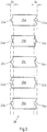
- Fig. 5 shows a schematic side view of a first column 28 of five batteries 20 ae each having a first pole 22 ae and in each case a second pole 24 ae. It can be seen that the batteries 20a-e are arranged one above the other in column 28. It can also be seen that the poles 22, 24 are arranged alternately. That is, for example, a positive pole 22a of the battery 20a is disposed in a plane having a negative pole 24b of a battery 20b. This is followed again by a positive pole 22c, followed by a negative pole 24d and again a plus pole 22e.
- the poles 22, 24 of the batteries 20 are arranged in a tolerance range 26, which in the present case is shown enlarged.
- the tolerance range 26 indicates within which range the poles can be arranged.
- the length 21 of the respective batteries ie the distance between the poles 22, 24 to each other, is subject to tolerances. It follows that the poles 22, 24 are not always coplanar, so that when connecting to a battery cell connector 1, this tolerance must be compensated.
- a first battery cell connector 1a would be disposed between the positive pole 22a and the negative pole 24b. Thereafter, the positive terminal 22b would be connected to a battery cell connector 1 having a negative terminal 24c. The positive pole 22c would be connected to the minus pole 24d via a battery cell connector. The positive pole 22d would be connected via a battery cell connector 1 to the negative terminal 24e. The positive pole 22e would be connected to a battery cell connector with a negative pole of a battery of another column 28.
- the battery cell connectors 1 along a column 28 would be arranged vertically, and a battery cell connector 1 connecting two columns 28 would be arranged horizontally.
- FIG. 6 shows two columns 28a, 28b side by side.
- the battery cell connectors 1 connect each positive pole 22a to the negative pole 24b, positive pole 22c to the negative pole 24d.
- the column 28a is connected via the positive pole 22e and a battery cell connector 1 to the negative pole 24e of the column 28b.
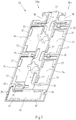
- Fig. 7 shows a carrier matrix 30 with a carrier 32. It can be seen that the carrier has 32 receptacles 34, 36, in each of which a battery cell connector 1 can be inserted.
- the pictures 34 are vertical pictures.
- the illustrated carrier 32 has two columns each with two vertical receptacles 34.
- a horizontal receptacle 36 is provided at the lower end of the carrier 32.
- two sword holders 38 are provided at the upper end of the carrier 32.
- locking lugs 35 are arranged on the carrier 32.
- the locking lugs 35 are arranged at the edges of the receptacles 34, 36 and allow a snap-in of battery cell connectors 1 in the receptacles 34, 26th
- retaining shoulders 37 can be seen. It can be seen that the retaining shoulders 37 spring back out of the surface of the carrier 32 and are arranged on the side of the carrier facing away from the battery.
- sword holders 38 are provided in the upper region of the carrier 32.
- the sword holders 38 have exceptions to the inclusion of swords 40, which protrude from the surface of the carrier 32.
- contact elements for contacting with battery poles are provided in the sword recordings.
- the contact elements are formed of different metals in order to ensure a sorted connection with battery poles of different polarity.
- plug 42 can be arranged.
- the battery cell connector 1 are positively engaged with the surface of the carrier 32 in the locking lugs 35.
- the battery cell connector 1 is inserted with the flat piece 8 in the vertical receptacle 34.
- the flat piece 8 is flush with the illustrated surface of the carrier 32.
- the first connector part 2 of the battery cell connector 1 is arranged in the vertical receptacle 34.
- the first connection part 2 is flush with the illustrated side of the carrier 32nd
- the battery cell connectors 1 are arranged in a column such that in a column in a first receptacle 34 first the connection part 2, then the connection part 6 and then the flat piece 8 of a first battery cell connector 1 is arranged and in a second second receptacle 34 arranged next thereto again Connecting part 2, then the connecting part 6 and then the sheet 8 of a second battery cell connector 1 is arranged.
- the vertical receptacle 34 and the horizontal receptacle 36 are shaped such that in one area the flat piece 8 can be received together with the second connecting part 2, and in a second area the first connecting part is receivable, wherein the receptacles 34, 36 also record the connecting part 6.
- side of the carrier 32 may also be connected to a guide matrix. This can be formed by guides for batteries.
- the batteries can be brought concentrically to the vents in the battery cell connectors.
- Fig. 9 shows the battery side facing away from the carrier 32. Again, the retaining shoulders 37 can be seen.
- a printed circuit board receptacle 40 is provided between the columns of vertical receptacles 34, in which a printed circuit board can be inserted.
- recesses 44 are provided in the region of the connection regions, via which the temperatures of the battery cell connectors can be tapped off.
- Fig. 10 shows the carrier 32 with inserted battery cell connectors 1 from the side facing away from the battery.
- a battery module from, for example, twelve batteries, six batteries each in columns are brought together to the carrier 32.
- the battery poles 22, 24 are aligned concentrically with the vents 14 of the battery cell connector 1 by the guides 41.
- the carrier 32 together with the battery cell connector 1 is pressed against the battery poles 22, 24.
- the battery cell connectors 1 are flexible, tolerance compensation in the region of the battery terminals 22, 24 can be realized.
- a single-variety contacting of the battery terminals is possible because the sheets 8 may be formed of a different material than the first connection parts 2.
- the carrier 32 together with Battery cell connector 1 was pressed against the battery terminals 22, 24, they are mechanically against the battery poles. Further, the contact areas of the swords 40 are applied to the upper batteries of the battery module.
- the battery terminals are welded to the battery cell connectors along the peripheral surfaces of the vent openings.
- the carrier matrix On an opposite side of the set of twelve batteries, the carrier matrix is complementarily shaped. This means that three vertical shots 34 are provided and no horizontal shots 36 and no sword shots 38. The current thus flows through all the batteries in series, and the voltage across all batteries can be tapped at the swords 40.
Landscapes
- Chemical & Material Sciences (AREA)
- Chemical Kinetics & Catalysis (AREA)
- Electrochemistry (AREA)
- General Chemical & Material Sciences (AREA)
- Connection Of Batteries Or Terminals (AREA)
- Battery Mounting, Suspending (AREA)
Claims (17)
- Matrice de support pour un connecteur d'éléments de batteries (1), ladite matrice comprenant- un support formé par un matériau non conducteur,- au moins un premier logement (34) formé dans une colonne servant au logement d'un connecteur d'éléments de batteries (1), où le premier logement (34) est formé de manière telle, que le connecteur d'éléments de batteries (1) reliant deux batteries disposées l'une au-dessus de l'autre dans la colonne puisse être emboîté dans le premier logement (34) le long d'une première direction,- au moins deux colonnes disposées l'une à côté de l'autre, dans une deuxième direction, et- un deuxième logement formé pour le logement d'un connecteur d'éléments de batteries (1) reliant des batteries disposées les unes à côté des autres dans deux colonnes, où le deuxième logement est formé de manière telle, que le connecteur d'éléments de batteries (1) puisse être emboîté dans le deuxième logement le long de la deuxième direction, et la deuxième direction est pratiquement normale à la première direction.
- Matrice de support selon la revendication 1, caractérisée en ce qu'un logement de plaquettes de circuits imprimés (40) prévu pour une plaquette de circuits imprimés est formé dans le support (32), entre les colonnes.
- Matrice de support selon la revendication 1, caractérisée en ce que le deuxième logement (36) et/ou le premier logement (34) sont formés pour servir de logement, à surface affleurante, d'un connecteur d'éléments de batteries (1).
- Matrice de support selon la revendication 1, caractérisée en ce que le deuxième logement (36) et/ou le premier logement (34) sont formés de manière telle, que, sur un côté du support (32), tourné vers une batterie, un connecteur d'éléments de batteries (1) comportant une pièce plate (8) et une première pièce de connexion (2) soit disposé en étant à fleur avec le support (32).
- Matrice de support selon la revendication 1, caractérisée en ce que le deuxième logement (32) et/ou le premier logement (34) présentent des ergots d'encliquetage (35) servant à la fixation, par complémentarité de forme, des connecteurs d'éléments de batteries (1).
- Matrice de support selon la revendication 5, caractérisée en ce que le deuxième logement (36) et/ou le premier logement (34) présentent, sur les côtés opposés aux ergots d'encliquetage (35), des épaulements de retenue (37) servant de paliers d'appui pour le logement du connecteur d'éléments de batteries (1).
- Matrice de support selon la revendication 1, caractérisée en ce que le support (32) est formé en étant composé de polyamide.
- Matrice de support selon la revendication 2, caractérisée en ce que le support (32) présente, dans le secteur de zones d'assemblage (12) des connecteurs d'éléments de batteries (1), des creux (44) formés entre le deuxième logement (36) et/ou le premier logement (34), et le logement des plaquettes de circuits imprimés.
- Matrice de support selon la revendication 8, caractérisée en ce que des conducteurs de connexion électrique sont guidés, dans les creux (44), entre la plaquette de circuits imprimés et les zones d'assemblage (12).
- Matrice de support selon la revendication 1, caractérisée en ce que deux logements en forme d'épée (38) agencés horizontalement l'un à côté de l'autre sont disposés, dans le support (32), sur le côté du support (32) placé à l'opposé du deuxième logement (36).
- Matrice de support selon la revendication 10, caractérisée en ce que les logements en forme d'épée (38) présentent des creux servant au logement d'éléments ensiformes dépassant de la surface du support (32).
- Matrice de support selon la revendication 1, caractérisée en ce que deux guidages (41) sont fixés sur le support (32), sur le côté tourné vers les batteries.
- Matrice de support selon la revendication 12, caractérisée en ce que les guidages (41) présentent des surfaces latérales au moins partiellement cylindriques.
- Matrice de support selon la revendication 12, caractérisée en ce que les guidages (41) sont d'un seul tenant et peuvent être assemblés, par complémentarité de forme, avec le support (32).
- Matrice de support selon la revendication 1, caractérisée en ce qu'à chaque fois deux premiers logements (34) agencés dans des colonnes (28a, 28b) disposées l'une à côté de l'autre sont formés de telle manière, qu'une zone supérieure d'un premier logement (34) est formée pour le logement d'une pièce de connexion, et une zone inférieure du premier logement (34) est formée pour le logement d'une pièce plate, et une zone supérieure d'un autre premier logement (34) est formée pour le logement d'une pièce plate, et une zone inférieure de l'autre premier logement (34) est formée pour le logement d'une pièce de connexion.
- Module d'éléments de batteries comprenant au moins une matrice de support selon la revendication 1, où une matrice de support est agencée sur un premier côté d'un ensemble se composant au moins de deux colonnes constituées à chaque fois de batteries disposées les unes au-dessus des autres, et une deuxième matrice de support présentant exclusivement des premiers logements est agencée sur le second côté de l'ensemble de colonnes.
- Procédé de fabrication d'un module d'éléments de batteries selon la revendication 16, comprenant les étapes consistant- à fabriquer un support,- à fixer des connecteurs d'éléments de batterie dans le deuxième logement (36) et dans le premier logement (34), où le deuxième logement (36) et le premier logement (34) sont formés de manière telle, que les connecteurs d'éléments de batteries (1) puissent être emboîtés dans le deuxième logement (36) et dans le premier logement (34),- à presser le support comprenant les connecteurs d'éléments de batteries, sur un jeu de batteries, et- à assembler, par continuité de matière, les bornes des batteries avec les connecteurs d'éléments de batteries.
Applications Claiming Priority (2)
| Application Number | Priority Date | Filing Date | Title |
|---|---|---|---|
| DE102009024514A DE102009024514A1 (de) | 2009-06-08 | 2009-06-08 | Trägermatrix für Batteriezellenverbinder |
| PCT/EP2010/057962 WO2010142658A1 (fr) | 2009-06-08 | 2010-06-08 | Matrice support pour connecteur d'éléments de batterie |
Publications (2)
| Publication Number | Publication Date |
|---|---|
| EP2441104A1 EP2441104A1 (fr) | 2012-04-18 |
| EP2441104B1 true EP2441104B1 (fr) | 2017-08-02 |
Family
ID=42727523
Family Applications (1)
| Application Number | Title | Priority Date | Filing Date |
|---|---|---|---|
| EP10722120.2A Not-in-force EP2441104B1 (fr) | 2009-06-08 | 2010-06-08 | Matrice support pour connecteur d'éléments de batterie |
Country Status (5)
| Country | Link |
|---|---|
| US (1) | US8999551B2 (fr) |
| EP (1) | EP2441104B1 (fr) |
| CN (1) | CN102460777B (fr) |
| DE (1) | DE102009024514A1 (fr) |
| WO (1) | WO2010142658A1 (fr) |
Families Citing this family (17)
| Publication number | Priority date | Publication date | Assignee | Title |
|---|---|---|---|---|
| DE102011109230A1 (de) * | 2011-08-03 | 2013-02-07 | Carl Freudenberg Kg | Vormontierte Einheit für ein Batteriemodul |
| DE102011080977A1 (de) * | 2011-08-16 | 2013-02-21 | Sb Limotive Company Ltd. | Zellverbinder, Batteriezellenmodul, Batterie, Verfahren zur Herstellung eines Zellverbinders und Kraftfahrzeug |
| DE102012004532A1 (de) * | 2012-03-06 | 2013-09-12 | Audi Ag | Batterie, insbesondere für ein Fahrzeug, und Verfahren zum Fertigen einer Batterie |
| DE102012205937A1 (de) * | 2012-04-12 | 2013-10-17 | Robert Bosch Gmbh | Sensorvorrichtung für einen elektrochemischen Energiespeicher, elektrochemischer Energiespeicher, Verfahren zum Herstellen einer Sensorvorrichtung für einen elektrochemischen Energiespeicher und Verfahren zum elektrischen Kontaktieren einer Sensorvorrichtung in einem elektrochemischen Energiespeicher |
| DE102012211171A1 (de) * | 2012-06-28 | 2014-01-02 | Robert Bosch Gmbh | Handwerkzeugakkuvorrichtung |
| DE102012107533B4 (de) * | 2012-08-16 | 2016-09-15 | C. & E. Fein Gmbh | Kompakt-Akku - Halterung für die Zellenverbinder |
| DE102012020358B3 (de) * | 2012-10-17 | 2014-02-13 | Audi Ag | Vorrichtung zur Montage eines Halterahmens mit darin aufgenommenen Stromschienen an einem Batteriemodul |
| DE102013213550A1 (de) * | 2013-07-11 | 2015-01-15 | Robert Bosch Gmbh | Batteriezelle mit einem prismatischen oder zylindrischen Gehäuse, Batteriemodul sowie Kraftfahrzeug |
| DE102013222090A1 (de) * | 2013-10-30 | 2015-04-30 | Volkswagen Aktiengesellschaft | Zellkontaktierungssystem, Batteriemodul mit einem Zellkontaktierungssystem und Fahrzeug mit zumindest einem derartigen Batteriemodul |
| US9368882B2 (en) * | 2013-11-15 | 2016-06-14 | Yazaki North America, Inc. | Electrical device with a busbar assembly having a frame providing access for laser welding |
| DE102014210425A1 (de) * | 2014-06-03 | 2015-12-03 | Thyssenkrupp Ag | Verfahren zum Befestigen von Sekundärbauteilen an einer Primärbauteilanordnung beim Herstellen einer Energiespeicherzelle |
| US9985265B2 (en) | 2015-04-13 | 2018-05-29 | Johnson Controls Technology Company | Flexible ribs of a bus bar carrier |
| EP3323160B1 (fr) * | 2015-09-30 | 2019-12-25 | BYD Company Limited | Connecteur pour batteries de puissance, module de batterie de puissance , bloc-batterie de puissance et véhicule |
| DE102016103841A1 (de) * | 2016-03-03 | 2017-09-07 | Johnson Controls Advanced Power Solutions Gmbh | Befestigung von elektrochemischen Zellen in einem Gehäuse eines Batteriemoduls |
| DE102017200311A1 (de) * | 2017-01-10 | 2018-07-12 | Bayerische Motoren Werke Aktiengesellschaft | Batterie, Trägerboard und Trägerboardelement mit Rastelementen |
| DE102018114764B4 (de) | 2018-06-20 | 2020-02-20 | Lisa Dräxlmaier GmbH | Steckbarer modulverbinder, verbindungssystem und verfahren zum elektrisch leitenden verbinden von zumindest zwei batteriemodulen |
| GB2631142B (en) | 2020-03-23 | 2025-02-19 | Transp Ip Holdings Llc | Electrical system for bus bar coupling |
Citations (1)
| Publication number | Priority date | Publication date | Assignee | Title |
|---|---|---|---|---|
| US20090104516A1 (en) * | 2005-05-23 | 2009-04-23 | Yasuo Yoshihara | Battery module and production method thereof |
Family Cites Families (11)
| Publication number | Priority date | Publication date | Assignee | Title |
|---|---|---|---|---|
| FR1600393A (fr) * | 1968-12-31 | 1970-07-20 | ||
| DE3033117C2 (de) * | 1980-09-03 | 1986-07-10 | Brown, Boveri & Cie Ag, 6800 Mannheim | Elektrochemische Speicherzelle |
| EP0344258A4 (en) * | 1987-10-23 | 1991-07-17 | James M. Shannon | Intercell connection and method and apparatus for making connector |
| JP3344231B2 (ja) * | 1996-08-21 | 2002-11-11 | 松下電器産業株式会社 | 電池の接続構造 |
| EP1030389B1 (fr) | 1997-03-24 | 2003-01-08 | Matsushita Electric Industrial Co., Ltd. | Boítier à piles comprenant des cables intégrés pour la mesure de la tension |
| CN1284755A (zh) | 1999-08-17 | 2001-02-21 | Gs-美尔可泰克株式会社 | 电池引线、使用该电池引线的电池组件和组合电池 |
| JP3848565B2 (ja) | 2001-11-27 | 2006-11-22 | 松下電器産業株式会社 | 電池間接続構造および電池モジュール並びに電池パック |
| JP2004127554A (ja) * | 2002-09-30 | 2004-04-22 | Sanyo Electric Co Ltd | 接続リード板およびリード板付き電池 |
| CN101218697B (zh) * | 2005-07-05 | 2010-12-08 | 松下电器产业株式会社 | 电池间连接装置 |
| KR100936262B1 (ko) | 2005-10-21 | 2010-01-12 | 주식회사 엘지화학 | 신규한 구조의 전기 접속용 버스 바 및 그것을 포함하고있는 전지모듈 |
| DE102007020295A1 (de) * | 2007-04-30 | 2008-11-20 | Siemens Ag | Vorrichtung zum Speichern von elektrischer Energie |
-
2009
- 2009-06-08 DE DE102009024514A patent/DE102009024514A1/de not_active Withdrawn
-
2010
- 2010-06-08 US US13/321,853 patent/US8999551B2/en not_active Expired - Fee Related
- 2010-06-08 WO PCT/EP2010/057962 patent/WO2010142658A1/fr not_active Ceased
- 2010-06-08 CN CN201080025415.4A patent/CN102460777B/zh not_active Expired - Fee Related
- 2010-06-08 EP EP10722120.2A patent/EP2441104B1/fr not_active Not-in-force
Patent Citations (1)
| Publication number | Priority date | Publication date | Assignee | Title |
|---|---|---|---|---|
| US20090104516A1 (en) * | 2005-05-23 | 2009-04-23 | Yasuo Yoshihara | Battery module and production method thereof |
Also Published As
| Publication number | Publication date |
|---|---|
| WO2010142658A1 (fr) | 2010-12-16 |
| CN102460777B (zh) | 2014-09-24 |
| US8999551B2 (en) | 2015-04-07 |
| CN102460777A (zh) | 2012-05-16 |
| US20120088143A1 (en) | 2012-04-12 |
| DE102009024514A1 (de) | 2010-12-09 |
| EP2441104A1 (fr) | 2012-04-18 |
Similar Documents
| Publication | Publication Date | Title |
|---|---|---|
| EP2441104B1 (fr) | Matrice support pour connecteur d'éléments de batterie | |
| EP2441103B2 (fr) | Connecteur d'éléments de batterie | |
| DE202009012647U1 (de) | Batteriezellenverbinder | |
| DE102009024513A1 (de) | Batteriezellenverbinder | |
| EP2989669B1 (fr) | Systeme de contacte de bateries et procede pour sa production | |
| EP2692001B1 (fr) | Batterie pour véhicule automobile | |
| EP3523841B1 (fr) | Module de stockage d'énergie et procédé d'assemblage | |
| DE202010012555U1 (de) | Batteriezellenverbinder mit Z-Schlag | |
| EP2727172A1 (fr) | Dispositif d'accumulation électrique | |
| EP2497134B1 (fr) | Procédé pour relier un pôle de batterie au niveau d'un premier élément de batterie à un pôle de batterie au niveau d'un second élément de batterie, batterie constituée d'éléments de batterie reliés entre eux et système de batteries | |
| DE102012005120A1 (de) | Verbindungssystem für eine Energiespeichereinrichtung und Energiespeichereinrichtung mit dem Verbindungssystem | |
| WO2011060969A1 (fr) | Connecteur d'éléments de batterie | |
| DE102013221872B4 (de) | Verbinder zur Verbindung von zellenförmigen elektrischen Elementen | |
| DE102010043885A1 (de) | Akkupack mit einer Vielzahl von Zellen und Verfahren zur Herstellung eines Akkupacks | |
| DE102012213673A1 (de) | Batteriemodul sowie Batterie und Kraftfahrzeug umfassend ein solches | |
| EP2692000B1 (fr) | Batterie pour véhicule automobile et procédé de production associé | |
| WO2015074735A1 (fr) | Batterie comportant une pluralité d'éléments de batterie à pôles reliés par des éléments de liaison | |
| DE102016106620A1 (de) | Elektrische Hochstrom-Fügestelle, die eine Teilmontage beseitigt | |
| EP2735039B1 (fr) | Système de mise en contact électrique des éléments d'un accumulateur d'énergie | |
| WO2018219966A1 (fr) | Élément de mise en contact pour un système de mise en contact de cellules pour un dispositif électrochimique et procédé servant à fabriquer un système de mise en contact de cellules pour un dispositif électrochimique | |
| DE102016208589A1 (de) | Elektrodenanordnung einer Batteriezelle, Elektrodenschicht und Batteriezelle sowie Verfahren zu deren Herstellung | |
| EP2697847B1 (fr) | Unité d'accumulation comportant un accumulateur d'énergie mis en contact de façon élastique | |
| EP2524407B1 (fr) | Batterie, système de batteries et procédé de connexion d'une pluralité de batteries | |
| DE102024120003B4 (de) | Zellkontaktiersystem | |
| DE102017006518A1 (de) | Vorrichtung zum Halten von elektrisch leitend verbundenen Bauelementen und Verfahren zur Herstellung einer Vorrichtung zum Halten von elektrisch leitend verbundenen Bauelementen |
Legal Events
| Date | Code | Title | Description |
|---|---|---|---|
| PUAI | Public reference made under article 153(3) epc to a published international application that has entered the european phase |
Free format text: ORIGINAL CODE: 0009012 |
|
| 17P | Request for examination filed |
Effective date: 20111104 |
|
| AK | Designated contracting states |
Kind code of ref document: A1 Designated state(s): AL AT BE BG CH CY CZ DE DK EE ES FI FR GB GR HR HU IE IS IT LI LT LU LV MC MK MT NL NO PL PT RO SE SI SK SM TR |
|
| DAX | Request for extension of the european patent (deleted) | ||
| RAP1 | Party data changed (applicant data changed or rights of an application transferred) |
Owner name: AUTO-KABEL MANAGEMENT GMBH |
|
| 17Q | First examination report despatched |
Effective date: 20140812 |
|
| REG | Reference to a national code |
Ref country code: DE Ref legal event code: R079 Ref document number: 502010013942 Country of ref document: DE Free format text: PREVIOUS MAIN CLASS: H01M0002200000 Ipc: H01M0002320000 |
|
| GRAP | Despatch of communication of intention to grant a patent |
Free format text: ORIGINAL CODE: EPIDOSNIGR1 |
|
| RIC1 | Information provided on ipc code assigned before grant |
Ipc: H01M 10/052 20100101ALN20170327BHEP Ipc: H01M 2/22 20060101ALI20170327BHEP Ipc: H01M 2/32 20060101AFI20170327BHEP Ipc: H01M 2/30 20060101ALI20170327BHEP Ipc: H01M 2/20 20060101ALI20170327BHEP |
|
| INTG | Intention to grant announced |
Effective date: 20170411 |
|
| GRAS | Grant fee paid |
Free format text: ORIGINAL CODE: EPIDOSNIGR3 |
|
| GRAA | (expected) grant |
Free format text: ORIGINAL CODE: 0009210 |
|
| AK | Designated contracting states |
Kind code of ref document: B1 Designated state(s): AL AT BE BG CH CY CZ DE DK EE ES FI FR GB GR HR HU IE IS IT LI LT LU LV MC MK MT NL NO PL PT RO SE SI SK SM TR |
|
| REG | Reference to a national code |
Ref country code: GB Ref legal event code: FG4D Free format text: NOT ENGLISH |
|
| REG | Reference to a national code |
Ref country code: CH Ref legal event code: EP Ref country code: AT Ref legal event code: REF Ref document number: 915379 Country of ref document: AT Kind code of ref document: T Effective date: 20170815 |
|
| REG | Reference to a national code |
Ref country code: IE Ref legal event code: FG4D Free format text: LANGUAGE OF EP DOCUMENT: GERMAN |
|
| REG | Reference to a national code |
Ref country code: DE Ref legal event code: R096 Ref document number: 502010013942 Country of ref document: DE |
|
| REG | Reference to a national code |
Ref country code: NL Ref legal event code: MP Effective date: 20170802 |
|
| REG | Reference to a national code |
Ref country code: LT Ref legal event code: MG4D |
|
| PG25 | Lapsed in a contracting state [announced via postgrant information from national office to epo] |
Ref country code: NO Free format text: LAPSE BECAUSE OF FAILURE TO SUBMIT A TRANSLATION OF THE DESCRIPTION OR TO PAY THE FEE WITHIN THE PRESCRIBED TIME-LIMIT Effective date: 20171102 Ref country code: SE Free format text: LAPSE BECAUSE OF FAILURE TO SUBMIT A TRANSLATION OF THE DESCRIPTION OR TO PAY THE FEE WITHIN THE PRESCRIBED TIME-LIMIT Effective date: 20170802 Ref country code: NL Free format text: LAPSE BECAUSE OF FAILURE TO SUBMIT A TRANSLATION OF THE DESCRIPTION OR TO PAY THE FEE WITHIN THE PRESCRIBED TIME-LIMIT Effective date: 20170802 Ref country code: LT Free format text: LAPSE BECAUSE OF FAILURE TO SUBMIT A TRANSLATION OF THE DESCRIPTION OR TO PAY THE FEE WITHIN THE PRESCRIBED TIME-LIMIT Effective date: 20170802 Ref country code: HR Free format text: LAPSE BECAUSE OF FAILURE TO SUBMIT A TRANSLATION OF THE DESCRIPTION OR TO PAY THE FEE WITHIN THE PRESCRIBED TIME-LIMIT Effective date: 20170802 Ref country code: FI Free format text: LAPSE BECAUSE OF FAILURE TO SUBMIT A TRANSLATION OF THE DESCRIPTION OR TO PAY THE FEE WITHIN THE PRESCRIBED TIME-LIMIT Effective date: 20170802 |
|
| PG25 | Lapsed in a contracting state [announced via postgrant information from national office to epo] |
Ref country code: LV Free format text: LAPSE BECAUSE OF FAILURE TO SUBMIT A TRANSLATION OF THE DESCRIPTION OR TO PAY THE FEE WITHIN THE PRESCRIBED TIME-LIMIT Effective date: 20170802 Ref country code: ES Free format text: LAPSE BECAUSE OF FAILURE TO SUBMIT A TRANSLATION OF THE DESCRIPTION OR TO PAY THE FEE WITHIN THE PRESCRIBED TIME-LIMIT Effective date: 20170802 Ref country code: PL Free format text: LAPSE BECAUSE OF FAILURE TO SUBMIT A TRANSLATION OF THE DESCRIPTION OR TO PAY THE FEE WITHIN THE PRESCRIBED TIME-LIMIT Effective date: 20170802 Ref country code: GR Free format text: LAPSE BECAUSE OF FAILURE TO SUBMIT A TRANSLATION OF THE DESCRIPTION OR TO PAY THE FEE WITHIN THE PRESCRIBED TIME-LIMIT Effective date: 20171103 Ref country code: IS Free format text: LAPSE BECAUSE OF FAILURE TO SUBMIT A TRANSLATION OF THE DESCRIPTION OR TO PAY THE FEE WITHIN THE PRESCRIBED TIME-LIMIT Effective date: 20171202 Ref country code: BG Free format text: LAPSE BECAUSE OF FAILURE TO SUBMIT A TRANSLATION OF THE DESCRIPTION OR TO PAY THE FEE WITHIN THE PRESCRIBED TIME-LIMIT Effective date: 20171102 |
|
| PG25 | Lapsed in a contracting state [announced via postgrant information from national office to epo] |
Ref country code: RO Free format text: LAPSE BECAUSE OF FAILURE TO SUBMIT A TRANSLATION OF THE DESCRIPTION OR TO PAY THE FEE WITHIN THE PRESCRIBED TIME-LIMIT Effective date: 20170802 Ref country code: CZ Free format text: LAPSE BECAUSE OF FAILURE TO SUBMIT A TRANSLATION OF THE DESCRIPTION OR TO PAY THE FEE WITHIN THE PRESCRIBED TIME-LIMIT Effective date: 20170802 Ref country code: DK Free format text: LAPSE BECAUSE OF FAILURE TO SUBMIT A TRANSLATION OF THE DESCRIPTION OR TO PAY THE FEE WITHIN THE PRESCRIBED TIME-LIMIT Effective date: 20170802 |
|
| REG | Reference to a national code |
Ref country code: DE Ref legal event code: R097 Ref document number: 502010013942 Country of ref document: DE |
|
| PG25 | Lapsed in a contracting state [announced via postgrant information from national office to epo] |
Ref country code: SM Free format text: LAPSE BECAUSE OF FAILURE TO SUBMIT A TRANSLATION OF THE DESCRIPTION OR TO PAY THE FEE WITHIN THE PRESCRIBED TIME-LIMIT Effective date: 20170802 Ref country code: SK Free format text: LAPSE BECAUSE OF FAILURE TO SUBMIT A TRANSLATION OF THE DESCRIPTION OR TO PAY THE FEE WITHIN THE PRESCRIBED TIME-LIMIT Effective date: 20170802 Ref country code: IT Free format text: LAPSE BECAUSE OF FAILURE TO SUBMIT A TRANSLATION OF THE DESCRIPTION OR TO PAY THE FEE WITHIN THE PRESCRIBED TIME-LIMIT Effective date: 20170802 Ref country code: EE Free format text: LAPSE BECAUSE OF FAILURE TO SUBMIT A TRANSLATION OF THE DESCRIPTION OR TO PAY THE FEE WITHIN THE PRESCRIBED TIME-LIMIT Effective date: 20170802 |
|
| PLBE | No opposition filed within time limit |
Free format text: ORIGINAL CODE: 0009261 |
|
| STAA | Information on the status of an ep patent application or granted ep patent |
Free format text: STATUS: NO OPPOSITION FILED WITHIN TIME LIMIT |
|
| 26N | No opposition filed |
Effective date: 20180503 |
|
| PG25 | Lapsed in a contracting state [announced via postgrant information from national office to epo] |
Ref country code: SI Free format text: LAPSE BECAUSE OF FAILURE TO SUBMIT A TRANSLATION OF THE DESCRIPTION OR TO PAY THE FEE WITHIN THE PRESCRIBED TIME-LIMIT Effective date: 20170802 |
|
| PG25 | Lapsed in a contracting state [announced via postgrant information from national office to epo] |
Ref country code: MT Free format text: LAPSE BECAUSE OF FAILURE TO SUBMIT A TRANSLATION OF THE DESCRIPTION OR TO PAY THE FEE WITHIN THE PRESCRIBED TIME-LIMIT Effective date: 20170802 |
|
| REG | Reference to a national code |
Ref country code: CH Ref legal event code: PL |
|
| GBPC | Gb: european patent ceased through non-payment of renewal fee |
Effective date: 20180608 |
|
| REG | Reference to a national code |
Ref country code: BE Ref legal event code: MM Effective date: 20180630 |
|
| REG | Reference to a national code |
Ref country code: IE Ref legal event code: MM4A |
|
| PG25 | Lapsed in a contracting state [announced via postgrant information from national office to epo] |
Ref country code: LU Free format text: LAPSE BECAUSE OF NON-PAYMENT OF DUE FEES Effective date: 20180608 Ref country code: MC Free format text: LAPSE BECAUSE OF FAILURE TO SUBMIT A TRANSLATION OF THE DESCRIPTION OR TO PAY THE FEE WITHIN THE PRESCRIBED TIME-LIMIT Effective date: 20170802 |
|
| PG25 | Lapsed in a contracting state [announced via postgrant information from national office to epo] |
Ref country code: LI Free format text: LAPSE BECAUSE OF NON-PAYMENT OF DUE FEES Effective date: 20180630 Ref country code: IE Free format text: LAPSE BECAUSE OF NON-PAYMENT OF DUE FEES Effective date: 20180608 Ref country code: GB Free format text: LAPSE BECAUSE OF NON-PAYMENT OF DUE FEES Effective date: 20180608 Ref country code: CH Free format text: LAPSE BECAUSE OF NON-PAYMENT OF DUE FEES Effective date: 20180630 Ref country code: FR Free format text: LAPSE BECAUSE OF NON-PAYMENT OF DUE FEES Effective date: 20180630 |
|
| PG25 | Lapsed in a contracting state [announced via postgrant information from national office to epo] |
Ref country code: BE Free format text: LAPSE BECAUSE OF NON-PAYMENT OF DUE FEES Effective date: 20180630 |
|
| PGFP | Annual fee paid to national office [announced via postgrant information from national office to epo] |
Ref country code: DE Payment date: 20190618 Year of fee payment: 10 |
|
| REG | Reference to a national code |
Ref country code: AT Ref legal event code: MM01 Ref document number: 915379 Country of ref document: AT Kind code of ref document: T Effective date: 20180608 |
|
| PG25 | Lapsed in a contracting state [announced via postgrant information from national office to epo] |
Ref country code: AT Free format text: LAPSE BECAUSE OF NON-PAYMENT OF DUE FEES Effective date: 20180608 |
|
| PG25 | Lapsed in a contracting state [announced via postgrant information from national office to epo] |
Ref country code: TR Free format text: LAPSE BECAUSE OF FAILURE TO SUBMIT A TRANSLATION OF THE DESCRIPTION OR TO PAY THE FEE WITHIN THE PRESCRIBED TIME-LIMIT Effective date: 20170802 |
|
| PG25 | Lapsed in a contracting state [announced via postgrant information from national office to epo] |
Ref country code: HU Free format text: LAPSE BECAUSE OF FAILURE TO SUBMIT A TRANSLATION OF THE DESCRIPTION OR TO PAY THE FEE WITHIN THE PRESCRIBED TIME-LIMIT; INVALID AB INITIO Effective date: 20100608 Ref country code: PT Free format text: LAPSE BECAUSE OF FAILURE TO SUBMIT A TRANSLATION OF THE DESCRIPTION OR TO PAY THE FEE WITHIN THE PRESCRIBED TIME-LIMIT Effective date: 20170802 |
|
| PG25 | Lapsed in a contracting state [announced via postgrant information from national office to epo] |
Ref country code: CY Free format text: LAPSE BECAUSE OF FAILURE TO SUBMIT A TRANSLATION OF THE DESCRIPTION OR TO PAY THE FEE WITHIN THE PRESCRIBED TIME-LIMIT Effective date: 20170802 Ref country code: MK Free format text: LAPSE BECAUSE OF NON-PAYMENT OF DUE FEES Effective date: 20170802 |
|
| PG25 | Lapsed in a contracting state [announced via postgrant information from national office to epo] |
Ref country code: AL Free format text: LAPSE BECAUSE OF FAILURE TO SUBMIT A TRANSLATION OF THE DESCRIPTION OR TO PAY THE FEE WITHIN THE PRESCRIBED TIME-LIMIT Effective date: 20170802 |
|
| REG | Reference to a national code |
Ref country code: DE Ref legal event code: R119 Ref document number: 502010013942 Country of ref document: DE |
|
| PG25 | Lapsed in a contracting state [announced via postgrant information from national office to epo] |
Ref country code: DE Free format text: LAPSE BECAUSE OF NON-PAYMENT OF DUE FEES Effective date: 20210101 |