EP3523841B1 - Module de stockage d'énergie et procédé d'assemblage - Google Patents
Module de stockage d'énergie et procédé d'assemblage Download PDFInfo
- Publication number
- EP3523841B1 EP3523841B1 EP17783450.4A EP17783450A EP3523841B1 EP 3523841 B1 EP3523841 B1 EP 3523841B1 EP 17783450 A EP17783450 A EP 17783450A EP 3523841 B1 EP3523841 B1 EP 3523841B1
- Authority
- EP
- European Patent Office
- Prior art keywords
- multiplicity
- carrier
- busbar
- cell
- energy storage
- Prior art date
- Legal status (The legal status is an assumption and is not a legal conclusion. Google has not performed a legal analysis and makes no representation as to the accuracy of the status listed.)
- Active
Links
Images

Classifications
-
- H—ELECTRICITY
- H01—ELECTRIC ELEMENTS
- H01M—PROCESSES OR MEANS, e.g. BATTERIES, FOR THE DIRECT CONVERSION OF CHEMICAL ENERGY INTO ELECTRICAL ENERGY
- H01M10/00—Secondary cells; Manufacture thereof
- H01M10/05—Accumulators with non-aqueous electrolyte
- H01M10/058—Construction or manufacture
-
- H—ELECTRICITY
- H01—ELECTRIC ELEMENTS
- H01M—PROCESSES OR MEANS, e.g. BATTERIES, FOR THE DIRECT CONVERSION OF CHEMICAL ENERGY INTO ELECTRICAL ENERGY
- H01M10/00—Secondary cells; Manufacture thereof
- H01M10/05—Accumulators with non-aqueous electrolyte
- H01M10/052—Li-accumulators
- H01M10/0525—Rocking-chair batteries, i.e. batteries with lithium insertion or intercalation in both electrodes; Lithium-ion batteries
-
- H—ELECTRICITY
- H01—ELECTRIC ELEMENTS
- H01M—PROCESSES OR MEANS, e.g. BATTERIES, FOR THE DIRECT CONVERSION OF CHEMICAL ENERGY INTO ELECTRICAL ENERGY
- H01M50/00—Constructional details or processes of manufacture of the non-active parts of electrochemical cells other than fuel cells, e.g. hybrid cells
- H01M50/20—Mountings; Secondary casings or frames; Racks, modules or packs; Suspension devices; Shock absorbers; Transport or carrying devices; Holders
- H01M50/204—Racks, modules or packs for multiple batteries or multiple cells
- H01M50/207—Racks, modules or packs for multiple batteries or multiple cells characterised by their shape
- H01M50/211—Racks, modules or packs for multiple batteries or multiple cells characterised by their shape adapted for pouch cells
-
- H—ELECTRICITY
- H01—ELECTRIC ELEMENTS
- H01M—PROCESSES OR MEANS, e.g. BATTERIES, FOR THE DIRECT CONVERSION OF CHEMICAL ENERGY INTO ELECTRICAL ENERGY
- H01M50/00—Constructional details or processes of manufacture of the non-active parts of electrochemical cells other than fuel cells, e.g. hybrid cells
- H01M50/20—Mountings; Secondary casings or frames; Racks, modules or packs; Suspension devices; Shock absorbers; Transport or carrying devices; Holders
- H01M50/218—Mountings; Secondary casings or frames; Racks, modules or packs; Suspension devices; Shock absorbers; Transport or carrying devices; Holders characterised by the material
- H01M50/22—Mountings; Secondary casings or frames; Racks, modules or packs; Suspension devices; Shock absorbers; Transport or carrying devices; Holders characterised by the material of the casings or racks
- H01M50/227—Organic material
-
- H—ELECTRICITY
- H01—ELECTRIC ELEMENTS
- H01M—PROCESSES OR MEANS, e.g. BATTERIES, FOR THE DIRECT CONVERSION OF CHEMICAL ENERGY INTO ELECTRICAL ENERGY
- H01M50/00—Constructional details or processes of manufacture of the non-active parts of electrochemical cells other than fuel cells, e.g. hybrid cells
- H01M50/20—Mountings; Secondary casings or frames; Racks, modules or packs; Suspension devices; Shock absorbers; Transport or carrying devices; Holders
- H01M50/249—Mountings; Secondary casings or frames; Racks, modules or packs; Suspension devices; Shock absorbers; Transport or carrying devices; Holders specially adapted for aircraft or vehicles, e.g. cars or trains
-
- H—ELECTRICITY
- H01—ELECTRIC ELEMENTS
- H01M—PROCESSES OR MEANS, e.g. BATTERIES, FOR THE DIRECT CONVERSION OF CHEMICAL ENERGY INTO ELECTRICAL ENERGY
- H01M50/00—Constructional details or processes of manufacture of the non-active parts of electrochemical cells other than fuel cells, e.g. hybrid cells
- H01M50/20—Mountings; Secondary casings or frames; Racks, modules or packs; Suspension devices; Shock absorbers; Transport or carrying devices; Holders
- H01M50/271—Lids or covers for the racks or secondary casings
-
- H—ELECTRICITY
- H01—ELECTRIC ELEMENTS
- H01M—PROCESSES OR MEANS, e.g. BATTERIES, FOR THE DIRECT CONVERSION OF CHEMICAL ENERGY INTO ELECTRICAL ENERGY
- H01M50/00—Constructional details or processes of manufacture of the non-active parts of electrochemical cells other than fuel cells, e.g. hybrid cells
- H01M50/50—Current conducting connections for cells or batteries
- H01M50/502—Interconnectors for connecting terminals of adjacent batteries; Interconnectors for connecting cells outside a battery casing
- H01M50/503—Interconnectors for connecting terminals of adjacent batteries; Interconnectors for connecting cells outside a battery casing characterised by the shape of the interconnectors
-
- H—ELECTRICITY
- H01—ELECTRIC ELEMENTS
- H01M—PROCESSES OR MEANS, e.g. BATTERIES, FOR THE DIRECT CONVERSION OF CHEMICAL ENERGY INTO ELECTRICAL ENERGY
- H01M50/00—Constructional details or processes of manufacture of the non-active parts of electrochemical cells other than fuel cells, e.g. hybrid cells
- H01M50/50—Current conducting connections for cells or batteries
- H01M50/502—Interconnectors for connecting terminals of adjacent batteries; Interconnectors for connecting cells outside a battery casing
- H01M50/507—Interconnectors for connecting terminals of adjacent batteries; Interconnectors for connecting cells outside a battery casing comprising an arrangement of two or more busbars within a container structure, e.g. busbar modules
-
- H—ELECTRICITY
- H01—ELECTRIC ELEMENTS
- H01M—PROCESSES OR MEANS, e.g. BATTERIES, FOR THE DIRECT CONVERSION OF CHEMICAL ENERGY INTO ELECTRICAL ENERGY
- H01M50/00—Constructional details or processes of manufacture of the non-active parts of electrochemical cells other than fuel cells, e.g. hybrid cells
- H01M50/50—Current conducting connections for cells or batteries
- H01M50/502—Interconnectors for connecting terminals of adjacent batteries; Interconnectors for connecting cells outside a battery casing
- H01M50/514—Methods for interconnecting adjacent batteries or cells
- H01M50/516—Methods for interconnecting adjacent batteries or cells by welding, soldering or brazing
-
- H—ELECTRICITY
- H01—ELECTRIC ELEMENTS
- H01M—PROCESSES OR MEANS, e.g. BATTERIES, FOR THE DIRECT CONVERSION OF CHEMICAL ENERGY INTO ELECTRICAL ENERGY
- H01M50/00—Constructional details or processes of manufacture of the non-active parts of electrochemical cells other than fuel cells, e.g. hybrid cells
- H01M50/50—Current conducting connections for cells or batteries
- H01M50/502—Interconnectors for connecting terminals of adjacent batteries; Interconnectors for connecting cells outside a battery casing
- H01M50/521—Interconnectors for connecting terminals of adjacent batteries; Interconnectors for connecting cells outside a battery casing characterised by the material
- H01M50/522—Inorganic material
-
- H—ELECTRICITY
- H01—ELECTRIC ELEMENTS
- H01M—PROCESSES OR MEANS, e.g. BATTERIES, FOR THE DIRECT CONVERSION OF CHEMICAL ENERGY INTO ELECTRICAL ENERGY
- H01M2220/00—Batteries for particular applications
- H01M2220/20—Batteries in motive systems, e.g. vehicle, ship, plane
-
- Y—GENERAL TAGGING OF NEW TECHNOLOGICAL DEVELOPMENTS; GENERAL TAGGING OF CROSS-SECTIONAL TECHNOLOGIES SPANNING OVER SEVERAL SECTIONS OF THE IPC; TECHNICAL SUBJECTS COVERED BY FORMER USPC CROSS-REFERENCE ART COLLECTIONS [XRACs] AND DIGESTS
- Y02—TECHNOLOGIES OR APPLICATIONS FOR MITIGATION OR ADAPTATION AGAINST CLIMATE CHANGE
- Y02E—REDUCTION OF GREENHOUSE GAS [GHG] EMISSIONS, RELATED TO ENERGY GENERATION, TRANSMISSION OR DISTRIBUTION
- Y02E60/00—Enabling technologies; Technologies with a potential or indirect contribution to GHG emissions mitigation
- Y02E60/10—Energy storage using batteries
-
- Y—GENERAL TAGGING OF NEW TECHNOLOGICAL DEVELOPMENTS; GENERAL TAGGING OF CROSS-SECTIONAL TECHNOLOGIES SPANNING OVER SEVERAL SECTIONS OF THE IPC; TECHNICAL SUBJECTS COVERED BY FORMER USPC CROSS-REFERENCE ART COLLECTIONS [XRACs] AND DIGESTS
- Y02—TECHNOLOGIES OR APPLICATIONS FOR MITIGATION OR ADAPTATION AGAINST CLIMATE CHANGE
- Y02P—CLIMATE CHANGE MITIGATION TECHNOLOGIES IN THE PRODUCTION OR PROCESSING OF GOODS
- Y02P70/00—Climate change mitigation technologies in the production process for final industrial or consumer products
- Y02P70/50—Manufacturing or production processes characterised by the final manufactured product
Definitions
- the present invention relates to an energy storage module according to the preamble of the first patent claim.
- the invention also relates to a method for assembling an energy storage module according to the preamble of patent claim 11.
- Such energy storage modules are used in many areas of technology.
- the present invention relates in particular to the field of energy storage modules for vehicles, where a vehicle can be an aircraft or watercraft, a track-guided vehicle, an off-road vehicle, or preferably a road vehicle.
- Road vehicles are understood to mean in particular passenger cars, trucks, buses or mobile homes.
- Different types of battery modules are installed in vehicles, including traction batteries (in particular in electric vehicles) and starter batteries (car batteries).
- a starter battery is to be defined in particular by the fact that it provides at least a portion of the energy, preferably all of the energy, which is necessary to start a vehicle and/or to supply internal vehicle systems (lighting, pumps, ignition).
- Lithium-ion accumulators are usually used as starter batteries, but these are heavy, particularly due to their low energy densities. Lithium-ion accumulators, on the other hand, have a high energy density. In addition, lithium-ion batteries have, for example, a longer service life, lower self-discharge, improved fast charging capability and shorter maintenance intervals than conventional lead-acid batteries.
- WO 2015/152527 A1 relates to a conventional energy storage module according to the preamble of independent patent claim 1.
- the invention is therefore based on the object of designing an energy storage module for series production, in particular large-scale production, more efficiently, in particular with regard to automated production processes in automotive applications. It is also an object of the present invention to design an energy storage module in such a way that it can be used expediently in modular production processes and is particularly well suited for later use in vehicles. Furthermore, an improved method for assembling such energy storage modules is to be specified.
- connection lug flat connection lug
- connection lug short form
- the energy storage module is preferably a starter battery for a vehicle and the electrochemical cells are particularly preferably lithium-ion cells, whereby the advantages of lithium-ion cells mentioned above in comparison to lead accumulators can be realized.
- the lithium-ion cell is preferably designed as a pouch cell.
- the inventive proposal to design the cell pack in such a way that the first and second flat connection lugs extend at least substantially perpendicularly from two opposite sides of the cell pack and to design the contacting device (at least) substantially comb-shaped results in an extremely compact design that is easy to assemble, i.e., can be assembled in a few and/or uncomplicated steps. At the same time, however, extremely secure and good contact between the electrochemical cells and the contacting device can also be achieved.
- substantially perpendicular from a side of the cell pack means that the angle between the side of the cell pack and the respective connection lug is within a range of 70 degrees to 110 degrees, preferably within a range of 80 degrees to 100 degrees, and particularly preferably within a range of 85 degrees to 95 degrees. In particular, it is of course extremely preferred in this context if the angle is 90°.
- the contacting device is therefore also modular, which further increases the modularity of the overall system, as different busbars can be installed. This creates more options for assembly (number of variants increases) and at the same time fewer restrictions (pre-determinations).
- the stability of the contacting device is increased by the at least one carrier, which can also have further centering or installation aids.
- the proposal according to the invention to construct the contacting device from at least one busbar and at least one carrier also aims to separate the functions.
- the at least one busbar fulfills the function of electrical contact
- the at least one carrier fulfills the function of a holder or fastening and/or centering or positioning.
- the material for the at least one carrier can be, for example, acrylonitrile butadiene styrene, polycarbonate, polyamide, polyvinyl chloride, polyethylene terephthalate, polyoxymethylene or a copolymer thereof.
- the energy storage module has two contacting devices, wherein a first of the two contacting devices contacts connection lugs on a first side of the two opposite sides of the cell pack, and wherein a second of the two contacting devices contacts connection lugs on a second side of the two opposite sides of the cell pack.
- each of the first and second flat connection lugs is received between two adjacent prongs of the at least one contacting device.
- connection lugs It is thus possible to electrically connect each of the connection lugs to the contacting device in a later work step.
- the proposal according to the invention thus provides a particularly quick and efficient assembly of an energy storage module, in particular that the comb-shaped contact device can be pushed onto the connection lugs of the electrochemical cells. It is therefore possible to assemble the energy storage module in just a few steps or to prepare it for a subsequent assembly step.
- pouch cells which can be formed directly into a cell package. This means that, for example, it is no longer necessary to connect several pouch cells in a previous assembly step. In particular, this also makes the application of the energy storage module more universal overall, as the individual cells or their connection tabs can be aligned differently to one another. This means that it is not necessary to determine in advance whether a series or parallel connection of individual cells is to be achieved.
- connection lugs which are suitable for bundling due to their different design.
- the use of individual contacting devices, i.e. one associated contacting device per connection lug, is also prevented and the number of parts is reduced.
- Lead time in this context is the time that elapses in the manufacture of a product between the start of the first work process and the completion of the last work process.
- the at least one busbar can be received or accommodated in the at least one carrier and/or can be fastened or fastened to it.
- the at least one carrier has defined areas in which the at least one busbar can be accommodated. Such areas can be realized, for example, by an outer contour of the carrier and/or by webs. In particular, this also ensures that the busbar is connected to the at least one carrier in a specific and intended manner.
- joining agents in particular adhesives, preferably those in the form of adhesive strips, are suitable for fastening.
- the at least one contacting device has a plurality of busbars, wherein the plurality of busbars has a first plurality of busbars made of a first material and a second plurality of busbars made of a second material, and wherein the first material differs from the second material.
- At least one of the plurality of busbars can have a sensor connection, in particular for a temperature sensor and/or current sensor.
- a first busbar of the plurality of busbars and a second busbar of the plurality of busbars may already have been welded in a previous work step.
- a busbar made of a first material and a second busbar made of a second material are to be welded together, it may be necessary to use a bimetallic plate to simplify the welding process. This is particularly useful when welding copper and aluminum. Accordingly, the contacting device can also have a bimetallic plate.
- the at least one carrier and/or the at least one busbar has centering devices.
- the bimetal plate also has a centering device.
- centering devices are preferably provided by holes and associated pins, with the at least one busbar and possibly the bimetal plate having holes and the at least one carrier having pins.
- the centering devices make it possible to design the assembly according to the "Poka Yoke" principle in such a way that the centering devices dictate the assembly. This means that a busbar can only be arranged in a certain orientation or only in a certain area of the carrier.
- the at least one busbar has a connection region for electrically contacting an electrical consumer.
- connection to the consumer does not have to be direct. Rather, for example, at least one further electrical connecting element can be arranged between the consumer and the energy storage module.
- connection area is arranged at an upper end, i.e. at an end of the busbar facing away from the prongs. This allows a particularly easily accessible connection area of the busbar to be created.
- the prongs of the at least one carrier and/or the prongs of the at least one busbar have chamfered end regions.
- the prongs of the at least one carrier have chamfered end regions and the prongs of the at least one busbar do not extend to the chamfered end regions of the prongs of the at least one carrier when the at least one busbar is received in the at least one carrier and/or fastened to it.
- the proposal according to the invention therefore still provides the advantages of a chamfered end region, in particular a simplification of assembly, and on the other hand the effort is reduced because only the prongs of the at least one support have chamfered end regions. Accordingly, it is no longer necessary to chamfer the busbars in a complex manner.
- a particularly simple design of the chamfered end regions is also possible, for example by means of a correspondingly shaped mold.
- the at least one carrier has a plurality of bores, wherein the at least one busbar has a plurality of associated bores, wherein the bores of the carrier are aligned with the bores of the busbar when the at least one busbar is received in the carrier and/or fastened to it.
- each of the holes of the plurality of holes of the busbar are provided in the connection area in order to be able to stably fasten it.
- holes can also be used additionally or exclusively to provide a mounting option for various sensors. This is particularly easy to implement if the sensors have connections with ring tongues.
- the corresponding fastening devices in particular screws, rivets or bolts, are also provided in this context.
- a threaded plate with a plurality of bores is arranged and aligned between the at least one carrier and the at least one busbar such that the bores of the threaded plate are aligned with the bores of the carrier and the bores of the busbar.
- the threaded plate is also provided in the connection area in order to support and stabilize it and/or to provide a fastening option.
- fastening means such as screws or bolts
- connection lugs of the plurality of electrochemical cells are bendable.
- the cell pack has cell carriers to accommodate the plurality of electrochemical cells and to arrange them in a stack.
- each carrier i.e. the cell carrier is designed such that it can accommodate two electrochemical cells.
- the cell carriers can be prepared in a previous work step or at a previous work station and can be equipped with one, preferably two electrochemical cells. Work processes can therefore generally be further simplified and optimized.
- the cell carriers can be designed in such a way that they have a large number of devices that simplify subsequent assembly.
- a lower region of the cell carrier it is possible, for example, for a lower region of the cell carrier to be designed in such a way that the at least one contacting device can be inserted and/or received in it at least in part.
- a stop can also be provided for a lower region of the contacting device, i.e. for the prongs, which enables precise positioning of the contacting device.
- centering devices and/or locking devices can be provided to simplify assembly and in particular to make it easy to insert and/or hold the contacting device.
- the cell pack has two end plates which are provided at both ends of the stacked electrochemical cells.
- the two end plates are arranged adjacent to the cell carriers and form a front or rear end of the cell package.
- the end plates and/or cell carriers are made of plastic, in particular of acrylonitrile-butadiene-styrene, polycarbonate, polyamide, polyvinyl chloride, polyethylene terephthalate, polyoxymethylene or a copolymer thereof.
- the cell carriers have bores, wherein the end plates have associated bores which are arranged and aligned in alignment with the bores of the cell carriers, wherein the cell package further has a plurality of rods which can be guided through the bores of the cell carriers and the end plates in order to connect them.
- an assembled cell carrier with at least one cell, preferably two cells can be assembled at a first work station and at a subsequent second work station the cell carriers can be connected together with the end plates to form a cell pack, which can then be passed on to a third work station.
- each cell carrier and in each end plate are particularly preferably provided on the two sides of the cell pack from which the connection lugs of the electrochemical cells do not extend; that is, on a top side and a bottom side of the cell pack.
- the described arrangement of the cell pack with a large number of rods is also advantageous because the rods together with the holes fulfill a centering function.
- the rods have threads at their ends to enable fastening devices to be screwed on.
- a foam plate is provided between an outer, i.e. a front and a rear, cell carrier and one of the end plates.
- the foam plates have a damping effect, which means that the cell pack and in particular the electrochemical cells can be protected from vibrations and/or shocks.
- the foam plate is preferably attached using an adhesive, with the foam plates particularly preferably being glued to the end plates.
- the energy storage module further comprises a module housing and a cover.
- Screws, bolts or rivets are particularly suitable as fastening means for the module housing and the cover.
- the cover and/or the module housing are preferably connected to the end plates of the cell stack, which have holes or threaded holes for this purpose.
- a large number of devices are provided on the cover, for example connections for sensors used in the energy storage module, ventilation devices and terminals for contacting an electrical consumer.
- the terminals for contacting an electrical consumer are electrically connected to the connection area or areas of the at least one busbar.
- the method further comprises the following step: pushing at least one second contacting device onto flat connection lugs on a second side of the two opposite sides of the cell pack, wherein the at least one second contacting device is essentially comb-shaped and has a plurality of prongs which are designed and arranged in such a way is that a connecting lug can be or is accommodated between two adjacent prongs.
- connection lugs have a protective film and the method for assembling an energy storage module further comprises the following step: removing the protective film from the connection lugs of the plurality of electrochemical cells.
- the protective film protects the connection lugs when assembling the energy storage module.
- the surface of the connection lugs is protected from surface damage, such as scratches, in order to maintain the surface of the connection lugs as flat as possible.
- the protective film can prevent unwanted contact with the connection lugs, which also increases occupational safety at the respective workstation.
- the method further comprises the following step: bending the connection lugs such that the electrochemical cells can be or are electrically connected to the at least one first and/or the at least one second contacting device.
- connection lugs are flat, a particularly large contact surface is created after bending.
- the cell pack has cell carriers for receiving the plurality of electrochemical cells and arranging them in a stack, and two end plates which are provided at both ends of the stacked electrochemical cells.
- the method further comprises the following step: welding the connection lugs of the plurality of electrochemical cells to the at least one first and/or the at least one second contacting device using a welding tool.
- welding can create a large contact or connection surface between the connection lugs and the contacting device within a short period of time. Due to the short processing time, welding is particularly suitable for use in automated production processes and is also extremely reliable. In addition, other connecting components, such as screws, can be dispensed with and the structure is further simplified. The electrical resistance of a welded connection is also significantly lower than that of a connection provided by screws, for example.
- the cell carriers naturally have devices that simplify or enable the welding tool to be picked up or inserted.
- An example of such a device is in the form of a gap.
- the cell pack, the contacting device and the energy storage module are described in such a way that relative terms refer to the installed state of the energy storage module.
- “in an upper region” means an upper region as seen in the installed state and "in a lower region” means a lower region as seen in the installed state.
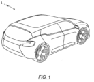
- FIG. 1 shows a schematic representation of a vehicle 1.
- An energy storage module 10 can be arranged in particular in a front area of the vehicle 1 in the direction of travel.
- the vehicle 1 can be an aircraft or watercraft, a tracked vehicle, an off-road vehicle, or preferably a road vehicle, where a road vehicle can be understood to mean a passenger car, a truck, a bus or a mobile home.
- the vehicle 1 is driven by a drive unit.
- the drive unit can be an internal combustion engine, an electric motor or a combination thereof.
- a vehicle 1 which has both an electric motor and an internal combustion engine is referred to as a hybrid vehicle.
- the energy storage module 10 can be provided as a starter battery.
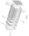
- FIG. 2 shows a cell pack 100 with a plurality of electrochemical cells 110 for use in the energy storage module 10 according to the invention.
- the plurality of electrochemical cells 110 are arranged in cell carriers 120, wherein a cell carrier 120 accommodates two electrochemical cells 110.
- the electrochemical cells 110 or the cell carriers 120 are arranged in such a way that first flat connection lugs 111 and second flat connection lugs 112 of the electrochemical cells 110 extend from two opposite sides of the cell pack 100. In particular, the two sides are the left and right sides of the cell pack.
- rods 140 are provided, which are received in or guided through holes in the cell carriers 120.
- the holes or rods 140 are only provided on the upper or lower side of the cell package 100.
- End plates 130 are provided on a front and rear side of the cell pack 100, which form a closure of the cell pack 100.
- the end plates 130 have associated holes through which the rods 140 can be received or passed.
- Foam plates 150 are arranged between the end plates 130 and a first or last cell carrier 120.
- the end plates 130 each have a recess which is designed in such a way in its shape and size to accommodate the foam plate 150 at least in some areas. It is preferably possible to provide the recess and/or the foam plate 150 with an adhesive device, such as adhesive strips.
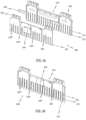
- FIG. 3a shows an exploded view of a contacting device 200 according to the invention.
- the contacting device 200 has a carrier 210 and four busbars 220, 220', 220" and 220′′′.
- busbars 220 are provided.
- the carrier 210 has a plurality of prongs 211, which have chamfered end regions 212. It can also be seen that the carrier 210 has centering devices in the form of knobs or pins, which can be received at least in corresponding holes in the two middle busbars 220' 220".
- the carrier 210 has three areas which are separated by webs, and thus provides three areas for the fixed accommodation of the busbars 220, 220', 220" and 220′′′.
- a front busbar 220 is accommodated in a front area
- the two middle busbars 220' and 220′′′ are accommodated in a middle area
- a rear busbar 220′′′ is accommodated in a rear area.
- Relative information such as "front” and “rear” also refers here to an installation state of the cell pack or the energy module.
- the front and rear portions of the carrier 210 have areas to receive a connection portion 223 of the front and rear bus bars 220 and 220′′′.
- each of the areas of the carrier 210 can have an adhesive strip 240 in order to connect the busbars 220, 220', 220" and 220′′′ to the carrier 210, that is to say to be able to attach it to it.
- the busbars 220 shown each have a plurality of prongs 221.
- the busbars 220 are made of different materials.
- the front busbar 220 is made of aluminum
- the adjacent middle busbar 220' is made of copper
- the other middle busbar 220" is made of aluminum
- the rear busbar 220′′′ is made of copper.
- a bimetal plate 250 is preferably provided.
- the two materials aluminum and copper can only be welded directly with great effort, so the bimetal plate 250 is used, which has a first side made of aluminum and a second side made of copper.
- the side of the bimetal plate 250 made of aluminum is welded to the busbar 220". Accordingly, the side of the bimetal plate 250 which is made of copper is welded to the busbar 220'.
- Threaded plates 230 are provided between the busbars 220 and the carrier 210.
- the area of the carrier 210 which receives the connection areas 223 of the busbars 220 and 220′′′ is also designed to be able to receive the threaded plate 230.
- FIG. 3b shows the contacting device 200 according to FIG. 3a in an assembled state.
- the busbars 220, 220', 220", 220′′′ are accommodated in the carrier 210.
- the prongs 211 of the carrier 210 are longer than the prongs 221 of the busbars 220, 220', 220" and 220"'. This offers the advantage that only the prongs 211 of the carrier 210 must have chamfered end regions 212. Accordingly, the busbars 220, 220', 220" and 220′′′ or their prongs 221 are easier to manufacture.
- the webs of the carrier between the front and the middle and between the middle and the rear area also serve to electrically isolate the busbars 220 and 220' or the busbars 220" and 220 ′′′ from each other.
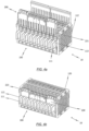
- FIGS. 4a, 4b and 4c show the energy storage module 10 in different production steps (states).
- FIG. 4a This shows the FIG. 4a the cell pack 100 and two contacting devices 200 before sliding on the contacting devices 200.
- FIG. 4b shows the cell pack 100 and the contacting devices 200 in a pushed-on or plugged-on state. It can be seen that the two contacting devices 200 are not or do not have to be identical. In particular, it can be seen that only one of the contacting devices 200 has the connection areas 223 of the busbar 220 and 220′′′. Accordingly, the carrier 210 is designed either with or without areas for receiving the connection areas 223.
- the first and second flat connection lugs 111 and 112 also have a protective film 113, which in an intermediate step between FIG. 4b and FIG. 4c is removed.
- the protective film 113 serves in particular to protect the surface of the connection lugs 111 and 112.
- connection lugs 111 and 112 have been bent in such a way that they enable electrical contact between the busbars 220, 220', 220" and 220′′′ and the electrochemical cells 110.
- contact areas between the connection lugs 111 and 112 and the busbars 220, 220', 220" and 220′′′ are relatively large due to the flat design of the connection lugs 111, 112.
- a lower region of the cell carrier 120 is designed to form a gap 121 in which a welding tool can be inserted in a subsequent work step.
- the cell pack 100 and in particular the end plates 130 also have, as shown in the FIG. 4a to FIG. 4c can be seen, centering devices. These can be seen in particular on the end plates 130 in the form of projections extending to the sides.
- the contacting devices 200 in particular the carrier 210, also have centering devices which are FIG. 4a for example in the form of struts extending parallel to the tines of the support.
- the carrier 210 as also in FIG. 4a to recognize, in an upper area a kind of rail, which in upper areas of the Cell carrier 120 can be attached. This is in particular a locking device.
- the carrier 210 can be accommodated in a lower region of the cell carrier 120.
- This lower region can simultaneously form a stop so that the contacting devices 200 can only be pushed onto the connection lugs 111 and 112 up to a certain position.
- the lower region of the cell carrier is in particular the same region in which the gap 121 is formed.
Landscapes
- Chemical & Material Sciences (AREA)
- Chemical Kinetics & Catalysis (AREA)
- Electrochemistry (AREA)
- General Chemical & Material Sciences (AREA)
- Engineering & Computer Science (AREA)
- Inorganic Chemistry (AREA)
- Manufacturing & Machinery (AREA)
- Aviation & Aerospace Engineering (AREA)
- Materials Engineering (AREA)
- Battery Mounting, Suspending (AREA)
- Connection Of Batteries Or Terminals (AREA)
Claims (15)
- Module de stockage d'énergie (10), présentant ce qui suit :- une pluralité de cellules électrochimiques (110) pour stocker de l'énergie électrique ; et- au moins un dispositif de mise en contact (200) pour la mise en contact électrique de la pluralité de cellules électrochimiques (110),dans lequel chacune de la pluralité de cellules électrochimiques (110) présente une première patte de connexion (111) réalisée de manière plane pour mettre en contact une première électrode de la cellule électrochimique (110) respective et une deuxième patte de connexion (112) réalisée de manière plane pour mettre en contact une deuxième électrode de la cellule électrochimique (110) respective, dans lequel la pluralité de cellules électrochimiques (110) est disposée en forme de pile et réalise un paquet de cellules (100) de telle sorte que la première et la deuxième patte de connexion (111, 112) réalisées de manière plane s'étendent de manière au moins substantiellement verticalement à partir de deux côtés opposés du paquet de cellules (100), dans lequel ledit au moins un dispositif de mise en contact (200) est réalisé substantiellement en forme de peigne et présente une pluralité de dents (211, 221) qui sont réalisées et disposées de telle sorte qu'une première ou une deuxième patte de connexion (111,112) peut être reçue ou est reçue entre deux dents (211, 221) voisines,caractérisé en ce queledit au moins un dispositif de mise en contact (200) présente au moins une barre omnibus (220) et au moins un support (210), dans lequel ladite au moins une barre omnibus (220) et ledit au moins un support (210) sont réalisés en forme de peigne et présentent la pluralité de dents (211, 221).
- Module de stockage d'énergie (10) selon la revendication 1,
dans lequel le module de stockage d'énergie (10) présente deux dispositifs de mise en contact (200), dans lequel un premier des deux dispositifs de mise en contact (200) met en contact des pattes de connexion (111, 112) sur un premier côté des deux côtés opposés du paquet de cellules (100), et dans lequel un deuxième des deux dispositifs de mise en contact (200) met en contact des pattes de connexion (111, 112) sur un deuxième côté des deux côtés opposés du paquet de cellules (100). - Module de stockage d'énergie (10) selon la revendication 1 ou 2,dans lequel chacune de la première et de la deuxième patte de connexion (111, 112) réalisées de manière plane est reçue respectivement entre deux dents (211, 221) voisines dudit au moins un dispositif de mise en contact (200), et/oudans lequel ladite au moins une barre omnibus (220) peut être reçue ou est reçue dans ledit au moins un support (210) et/ou peut être fixée ou est fixée à celui-ci, et/oudans lequel ledit au moins un dispositif de mise en contact (200) présente une pluralité de barres omnibus (220, 220', 220", 220"'), et dans lequel la pluralité de barres omnibus (220, 220', 220", 220"') présente une première pluralité de barres omnibus (220, 220") d'un premier matériau et une deuxième pluralité de barres omnibus (220', 220"') d'un deuxième matériau, le premier matériau étant différent du deuxième matériau, et/oudans lequel ledit au moins un support (210) et/ou ladite au moins une barre omnibus (220) présentent des dispositifs de centrage, et/ou dans lequel ladite au moins une barre omnibus (220) présente une zone de connexion (223) pour la mise en contact électrique d'un consommateur électrique.
- Module de stockage d'énergie (10) selon l'une quelconque des revendications 1 à 3,dans lequel les dents (211) du au moins un support (210) et/ou les dents (221) de ladite au moins une barre omnibus (220) présentent des zones d'extrémité chanfreinées (212),dans lequel de préférence :- les dents (211) du au moins un support (210) présentent des zones d'extrémité chanfreinées (212), et- les dents (221) de ladite au moins une barre omnibus (220) ne s'étendent pas jusqu'à la zone d'extrémité chanfreinée (212) des dents (211) du au moins un support (210) lorsque ladite au moins une barre omnibus (220) est reçue dans ledit au moins un support (210) et/ou est fixée à celui-ci.
- Module de stockage d'énergie (10) selon l'une quelconque des revendications 1 à 4,dans lequel ledit au moins un support (210) présente une pluralité d'alésages, et dans lequel ladite au moins une barre omnibus (220) présente une pluralité d'alésages associés, dans lequel les alésages du support (210) sont en affleurement avec les alésages de la barre omnibus (220) lorsque ladite au moins une barre omnibus (220) est reçue dans le support (210) et/ou est fixée à celui-ci,dans lequel une plaque filetée (230) pourvue d'une pluralité d'alésages est disposée et alignée entre ledit au moins un support (210) et ladite au moins une barre omnibus (220) de telle sorte que les alésages de la plaque filetée (230) sont en affleurement avec les alésages du support (210) et les alésages de la barre omnibus (220).
- Module de stockage d'énergie (10) selon l'une quelconque des revendications 1 à 5,dans lequel les pattes de connexion (111, 112) de la pluralité de cellules électrochimiques (110) peuvent être pliées, et/oudans lequel le module de stockage d'énergie (10) présente en outre un boîtier de module et un couvercle.
- Module de stockage d'énergie (10) selon l'une quelconque des revendications 1 à 6,
dans lequel le paquet de cellules (100) présente des supports de cellules (120) pour recevoir et disposer en forme de pile la pluralité de cellules électrochimiques (110). - Module de stockage d'énergie (10) selon l'une quelconque des revendications 1 à 7,
dans lequel le paquet de cellules (100) présente deux plaques d'extrémité (130) qui sont prévues aux deux extrémités des cellules électrochimiques (110) disposées en forme de pile. - Module de stockage d'énergie (10) selon la revendication 7 ou 8,
dans lequel les supports de cellule (120) présentent des alésages, et dans lequel les plaques d'extrémité (130) présentent des alésages associés qui sont disposés et alignés en affleurement avec les alésages des supports de cellule (120), dans lequel le paquet de cellules (100) présente en outre une pluralité de barres (140) qui peuvent passer à travers les alésages des supports de cellule (120) et des plaques d'extrémité (130) afin de les relier. - Module de stockage d'énergie selon la revendication 8 ou 9,
dans lequel une plaque de mousse (150) est prévue respectivement entre un support de cellule (120) extérieur et l'une des plaques d'extrémité (130). - Procédé permettant d'assembler un module de stockage d'énergie (10), le procédé présentant les étapes suivantes consistant à :- disposer en forme de pile une pluralité de cellules électrochimiques (110) en un paquet de cellules (100), dans lequel chacune de la pluralité de cellules électrochimiques (110) présente une première patte de connexion (111) réalisée de manière plane pour mettre en contact une première électrode de la cellule électrochimique (110) respective et une deuxième patte de connexion (112) réalisée de manière plane pour mettre en contact une deuxième électrode de la cellule électrochimique (110) respective, et dans lequel le paquet de cellules (100) est réalisé de telle sorte que la première et la deuxième patte de connexion (111, 112) réalisées de manière plane s'étendent au moins substantiellement verticalement à partir de deux côtés opposés du paquet de cellules (100) ;- pousser au moins un premier dispositif de mise en contact (200) sur des pattes de connexion (111, 112) réalisées de manière plane sur un premier côté des deux côtés opposés du paquet de cellules (100), dans lequel ledit au moins un premier dispositif de mise en contact (200) est réalisé substantiellement en forme de peigne et présente une pluralité de dents (211, 221) qui sont réalisées et disposées de telle sorte qu'une patte de connexion (111, 112) peut être reçue ou est reçue entre deux dents (211, 221) voisines, respectivement,caractérisé en ce que
ledit au moins un premier et/ou ledit au moins un deuxième dispositif de mise en contact (200) présentent au moins une barre omnibus (220) et au moins un support (210), dans lequel ladite au moins une barre omnibus (220) et ledit au moins un support (210) sont réalisés en forme de peigne et présentent une pluralité de dents (211, 221). - Procédé selon la revendication 11, le procédé présentant en outre l'étape suivante consistant à :- pousser au moins un deuxième dispositif de mise en contact (200) sur des pattes de connexion (111, 112) réalisées de manière plane sur un deuxième côté des deux côtés opposés du paquet de cellules (100), dans lequel ledit au moins un deuxième dispositif de mise en contact (200) est réalisé substantiellement en forme de peigne et présente une pluralité de dents (211, 221) qui sont réalisées et disposées de telle sorte que respectivement une patte de connexion (111, 112) peut être reçue ou est reçue entre deux dents (211, 221) voisines, et/oudans lequel les pattes de connexion (111, 112) présentent un film de protection (113), et dans lequel le procédé présente en outre les étapes suivantes consistant à :- retirer le film de protection (113) des pattes de connexion (111, 112) de la pluralité de cellules électrochimiques (110), et/ou- plier les pattes de connexion (111, 112) de telle sorte que les cellules électrochimiques (110) peuvent être reliées ou sont reliées électriquement audit au moins un premier et/ou audit au moins un deuxième dispositif de mise en contact (200).
- Procédé selon la revendication 11 ou 12, dans lequel le paquet de cellules (100) présente des supports de cellule (120) pour recevoir et disposer en pile la pluralité de cellules électrochimiques (110), ainsi que deux plaques d'extrémité (130) qui sont prévues aux deux extrémités des cellules électrochimiques (110) disposées en forme de pile.
- Procédé selon l'une quelconque des revendications 11 à 13, le procédé présentant en outre l'étape suivante consistant à :- souder les pattes de connexion (111, 112) de la pluralité de cellules électrochimiques (110) audit au moins un premier et/ou au moins un deuxième dispositif de mise en contact (200) en utilisant un outil à souder.
- Procédé selon la revendication 13 ou la revendication 14,
dans lequel l'outil à souder et/ou le support de cellule (120) sont réalisés de telle sorte que l'outil à souder peut être reçu au moins par endroits dans les supports de cellule (120) et/ou peut être inséré dans les supports de cellule (120).
Priority Applications (1)
| Application Number | Priority Date | Filing Date | Title |
|---|---|---|---|
| EP24214724.7A EP4576359A1 (fr) | 2016-10-06 | 2017-10-06 | Module de stockage d'énergie et procédé d'assemblage |
Applications Claiming Priority (2)
| Application Number | Priority Date | Filing Date | Title |
|---|---|---|---|
| DE102016118977.4A DE102016118977B4 (de) | 2016-10-06 | 2016-10-06 | Energiespeichermodul und Verfahren zum Zusammenbau |
| PCT/EP2017/075488 WO2018065580A1 (fr) | 2016-10-06 | 2017-10-06 | Module de stockage d'énergie et procédé d'assemblage |
Related Child Applications (2)
| Application Number | Title | Priority Date | Filing Date |
|---|---|---|---|
| EP24214724.7A Division EP4576359A1 (fr) | 2016-10-06 | 2017-10-06 | Module de stockage d'énergie et procédé d'assemblage |
| EP24214724.7A Division-Into EP4576359A1 (fr) | 2016-10-06 | 2017-10-06 | Module de stockage d'énergie et procédé d'assemblage |
Publications (2)
| Publication Number | Publication Date |
|---|---|
| EP3523841A1 EP3523841A1 (fr) | 2019-08-14 |
| EP3523841B1 true EP3523841B1 (fr) | 2025-02-26 |
Family
ID=60080787
Family Applications (2)
| Application Number | Title | Priority Date | Filing Date |
|---|---|---|---|
| EP24214724.7A Pending EP4576359A1 (fr) | 2016-10-06 | 2017-10-06 | Module de stockage d'énergie et procédé d'assemblage |
| EP17783450.4A Active EP3523841B1 (fr) | 2016-10-06 | 2017-10-06 | Module de stockage d'énergie et procédé d'assemblage |
Family Applications Before (1)
| Application Number | Title | Priority Date | Filing Date |
|---|---|---|---|
| EP24214724.7A Pending EP4576359A1 (fr) | 2016-10-06 | 2017-10-06 | Module de stockage d'énergie et procédé d'assemblage |
Country Status (5)
| Country | Link |
|---|---|
| US (2) | US11196118B2 (fr) |
| EP (2) | EP4576359A1 (fr) |
| CN (2) | CN109792014A (fr) |
| DE (1) | DE102016118977B4 (fr) |
| WO (1) | WO2018065580A1 (fr) |
Families Citing this family (15)
| Publication number | Priority date | Publication date | Assignee | Title |
|---|---|---|---|---|
| US11342638B2 (en) | 2017-06-01 | 2022-05-24 | Clarios Advanced Solutions Gmbh | Electrochemical cell unit, energy storage module and method for the assembly thereof |
| DE202018100148U1 (de) * | 2018-01-11 | 2019-04-12 | WeightWorks GmbH | Energiespeichervorrichtung, Kraftfahrzeug bzw. Überwachungssystem mit einer solchen Energiespeichervorrichtung und Verwendung einer solchen Energiespeichervorrichtung |
| DE102018209541A1 (de) * | 2018-05-29 | 2019-12-05 | Robert Bosch Gmbh | Verfahren zum Verbinden von elektrochemischen Zellen, Batteriemodul und System zum Herstellen eines Batteriemoduls |
| JP6898889B2 (ja) * | 2018-07-06 | 2021-07-07 | 矢崎総業株式会社 | 組電池 |
| DE102018006621A1 (de) * | 2018-08-21 | 2020-02-27 | Daimler Ag | Batterieeinheit, Verfahren zum elektrischen Verschalten von Zellblöcken einer Batterieeinheit und Verfahren zum Auftrennen einer elektrischen Verschaltung von Zellblöcken einer Batterieeinheit |
| KR102892839B1 (ko) * | 2019-02-08 | 2025-11-27 | 에스케이온 주식회사 | 배터리 모듈 및 이의 제조방법 |
| CN109888159A (zh) * | 2019-02-28 | 2019-06-14 | 力神动力电池系统有限公司 | 一种动力电池软包模组 |
| DE102019120496A1 (de) * | 2019-07-30 | 2021-02-04 | Lisa Dräxlmaier GmbH | Anschlusselement zur elektrischen kontaktierung und verfarhen zur herstellung eines anschlusselements |
| KR102877585B1 (ko) * | 2020-04-24 | 2025-10-27 | 주식회사 엘지에너지솔루션 | 전지 모듈 및 이를 포함하는 전지팩 |
| CN213243051U (zh) * | 2020-11-04 | 2021-05-18 | 东莞市硅翔绝缘材料有限公司 | 软包电芯连接和信号采集装置 |
| SE545904C2 (en) * | 2021-06-30 | 2024-03-12 | Scania Cv Ab | An apparatus for the electrical interconnection of a plurality of electric battery cell units |
| DE102021207235A1 (de) * | 2021-07-08 | 2023-01-12 | Mahle International Gmbh | Batterie |
| DE102022116265B4 (de) | 2022-06-29 | 2025-04-24 | Webasto SE | Verfahren zum Herstellen einer Batterieanordnung und Montagevorrichtung |
| KR20240128476A (ko) * | 2023-02-17 | 2024-08-26 | 에스케이온 주식회사 | 배터리모듈 및 배터리모듈의 제조방법 |
| KR20240128468A (ko) | 2023-02-17 | 2024-08-26 | 에스케이온 주식회사 | 배터리 셀, 배터리모듈 및 배터리모듈의 제조방법 |
Family Cites Families (18)
| Publication number | Priority date | Publication date | Assignee | Title |
|---|---|---|---|---|
| US1259193A (en) * | 1917-10-06 | 1918-03-12 | Omar M Polk | Storage battery. |
| DE4240337C2 (de) * | 1992-12-01 | 1997-06-19 | Deutsche Automobilgesellsch | Elektrochemischer Speicher und Verfahren zu dessen Herstellung |
| KR100684764B1 (ko) * | 2005-07-29 | 2007-02-20 | 삼성에스디아이 주식회사 | 이차 전지 모듈과 이에 적용되는 단위 전지 고정용연결로드 |
| KR101141379B1 (ko) * | 2010-07-06 | 2012-05-03 | 삼성전기주식회사 | 에너지 저장 모듈 |
| WO2013051012A2 (fr) * | 2011-06-06 | 2013-04-11 | Tata Motors Limited | Dispositif de barre omnibus bimétallique pour ensembles d'éléments de batterie |
| KR101480385B1 (ko) * | 2011-12-14 | 2015-01-09 | 주식회사 엘지화학 | 버스 바 어셈블리가 전면에 장착된 전지모듈 어셈블리 및 이를 포함하는 중대형 전지팩 |
| KR101447062B1 (ko) * | 2012-01-26 | 2014-11-03 | 주식회사 엘지화학 | 전지모듈 및 이를 포함하는 전지팩 |
| CN202585590U (zh) * | 2012-04-13 | 2012-12-05 | 万向电动汽车有限公司 | 一种电动汽车电源模块结构 |
| US9225035B1 (en) * | 2012-06-06 | 2015-12-29 | KleenSpeed Technologies Inc. | Low profile battery module and improved thermal interface |
| US9551064B2 (en) * | 2012-06-18 | 2017-01-24 | Hzo, Inc. | Moisture-resistant and anti-corrosive energy storage devices and associated methods |
| JP5880473B2 (ja) * | 2013-02-27 | 2016-03-09 | 株式会社デンソー | 電池ユニット |
| DE102013210585A1 (de) * | 2013-06-07 | 2014-12-11 | Robert Bosch Gmbh | Gehäusevorrichtung für zumindest eine Energiespeicherzelle und Verfahren zum Herstellen einer Gehäusevorrichtung für zumindest eine Energiespeicherzelle |
| KR102117848B1 (ko) * | 2013-11-13 | 2020-06-02 | 에스케이이노베이션 주식회사 | 배터리 모듈 및 이를 제작하는 방법 |
| KR102221801B1 (ko) * | 2014-02-04 | 2021-03-02 | 삼성에스디아이 주식회사 | 버스바 모듈 |
| US10396334B2 (en) * | 2014-03-31 | 2019-08-27 | Lg Chem, Ltd. | Battery module and battery pack comprising same |
| WO2015152527A1 (fr) | 2014-03-31 | 2015-10-08 | 주식회사 엘지화학 | Module de batterie et bloc-batterie le comportant |
| KR20150115250A (ko) * | 2014-04-03 | 2015-10-14 | 주식회사 엘지화학 | 내부 텐션-바를 포함하는 배터리 팩 |
| CN105514498B (zh) * | 2015-12-01 | 2019-04-26 | 浙江超威创元实业有限公司 | 一种便于自动组装的动力电池模组及电动车 |
-
2016
- 2016-10-06 DE DE102016118977.4A patent/DE102016118977B4/de active Active
-
2017
- 2017-10-06 WO PCT/EP2017/075488 patent/WO2018065580A1/fr not_active Ceased
- 2017-10-06 US US16/332,787 patent/US11196118B2/en active Active
- 2017-10-06 CN CN201780061066.3A patent/CN109792014A/zh active Pending
- 2017-10-06 EP EP24214724.7A patent/EP4576359A1/fr active Pending
- 2017-10-06 CN CN202410041478.2A patent/CN118040065A/zh active Pending
- 2017-10-06 EP EP17783450.4A patent/EP3523841B1/fr active Active
-
2021
- 2021-11-11 US US17/524,216 patent/US11888169B2/en active Active
Also Published As
| Publication number | Publication date |
|---|---|
| EP4576359A1 (fr) | 2025-06-25 |
| US11196118B2 (en) | 2021-12-07 |
| US11888169B2 (en) | 2024-01-30 |
| DE102016118977A1 (de) | 2018-04-12 |
| DE102016118977B4 (de) | 2022-01-20 |
| CN109792014A (zh) | 2019-05-21 |
| CN118040065A (zh) | 2024-05-14 |
| US20220069397A1 (en) | 2022-03-03 |
| WO2018065580A1 (fr) | 2018-04-12 |
| US20190221798A1 (en) | 2019-07-18 |
| EP3523841A1 (fr) | 2019-08-14 |
Similar Documents
| Publication | Publication Date | Title |
|---|---|---|
| EP3523841B1 (fr) | Module de stockage d'énergie et procédé d'assemblage | |
| EP2692001B1 (fr) | Batterie pour véhicule automobile | |
| EP2989669B1 (fr) | Systeme de contacte de bateries et procede pour sa production | |
| EP2243178B1 (fr) | Batterie avec plusieurs éléments individuels | |
| EP2441104B1 (fr) | Matrice support pour connecteur d'éléments de batterie | |
| EP2740169B1 (fr) | Cellule unitaire pour batterie et batterie | |
| DE102014205465A1 (de) | Verbinder zur Verbindung von zellenförmigen elektrischen Elementen und Verfahren zur Installation eines solchen Verbinders auf einer Batterieeinheit | |
| WO2011116801A1 (fr) | Batterie comprenant une pluralité d'éléments individuels | |
| DE102013221872B4 (de) | Verbinder zur Verbindung von zellenförmigen elektrischen Elementen | |
| DE102010046642A1 (de) | Elektrischer Energiespeicher sowie Leiterelement für einen solchen Energiespeicher | |
| DE102010031462A1 (de) | Batteriezellenmodul, Batterie und Kraftfahrzeug | |
| EP3631877B1 (fr) | Module d'accumulation d'énergie et procédé pour l'assemblage de ceux-ci | |
| EP2692000B1 (fr) | Batterie pour véhicule automobile et procédé de production associé | |
| WO2015074735A1 (fr) | Batterie comportant une pluralité d'éléments de batterie à pôles reliés par des éléments de liaison | |
| EP2735039B1 (fr) | Système de mise en contact électrique des éléments d'un accumulateur d'énergie | |
| DE112021000593T5 (de) | Energiespeichergerät | |
| DE102010013031A1 (de) | Batterie mit einem Zellenstapel von Batterieeinzelzellen | |
| DE102019131150A1 (de) | Komponentenpackung von technischen Komponenten sowie technische Komponente | |
| DE102008059958A1 (de) | Batterie, insbesondere Fahrzeugbatterie | |
| DE102016118751B4 (de) | Energiespeichersystem, energiespeichermodul und -anordnung sowie verfahren zum zusammenbau eines energiespeichermoduls | |
| DE102022132732A1 (de) | Batteriezelle für eine Fahrzeugbatterie oder andere Anwendungen und Verfahren zum Herstellen einer solchen Batteriezelle | |
| DE102022103702A1 (de) | Batteriezelle | |
| DE102012018088A1 (de) | Vorrichtung zum elektrischen Kontaktieren von prismatischen Batterieeinzelzellen | |
| DE102023123394A1 (de) | System zum durchstechen von flachsteckeranschlüssen für traktionsbatteriepacks | |
| DE212023000160U1 (de) | Batteriezelle und Batteriemodul, das diese Zelle einschließt |
Legal Events
| Date | Code | Title | Description |
|---|---|---|---|
| STAA | Information on the status of an ep patent application or granted ep patent |
Free format text: STATUS: UNKNOWN |
|
| STAA | Information on the status of an ep patent application or granted ep patent |
Free format text: STATUS: THE INTERNATIONAL PUBLICATION HAS BEEN MADE |
|
| PUAI | Public reference made under article 153(3) epc to a published international application that has entered the european phase |
Free format text: ORIGINAL CODE: 0009012 |
|
| STAA | Information on the status of an ep patent application or granted ep patent |
Free format text: STATUS: REQUEST FOR EXAMINATION WAS MADE |
|
| 17P | Request for examination filed |
Effective date: 20190401 |
|
| AK | Designated contracting states |
Kind code of ref document: A1 Designated state(s): AL AT BE BG CH CY CZ DE DK EE ES FI FR GB GR HR HU IE IS IT LI LT LU LV MC MK MT NL NO PL PT RO RS SE SI SK SM TR |
|
| AX | Request for extension of the european patent |
Extension state: BA ME |
|
| DAV | Request for validation of the european patent (deleted) | ||
| DAX | Request for extension of the european patent (deleted) | ||
| RAP1 | Party data changed (applicant data changed or rights of an application transferred) |
Owner name: CLARIOS ADVANCED SOLUTIONS GMBH |
|
| STAA | Information on the status of an ep patent application or granted ep patent |
Free format text: STATUS: EXAMINATION IS IN PROGRESS |
|
| 17Q | First examination report despatched |
Effective date: 20211206 |
|
| REG | Reference to a national code |
Ref country code: DE Ref legal event code: R079 Free format text: PREVIOUS MAIN CLASS: H01M0002100000 Ipc: H01M0050211000 Ref document number: 502017016717 Country of ref document: DE |
|
| RIC1 | Information provided on ipc code assigned before grant |
Ipc: H01M 50/522 20210101ALI20240312BHEP Ipc: H01M 50/516 20210101ALI20240312BHEP Ipc: H01M 50/507 20210101ALI20240312BHEP Ipc: H01M 50/271 20210101ALI20240312BHEP Ipc: H01M 50/227 20210101ALI20240312BHEP Ipc: H01M 50/211 20210101AFI20240312BHEP |
|
| GRAP | Despatch of communication of intention to grant a patent |
Free format text: ORIGINAL CODE: EPIDOSNIGR1 |
|
| STAA | Information on the status of an ep patent application or granted ep patent |
Free format text: STATUS: GRANT OF PATENT IS INTENDED |
|
| INTG | Intention to grant announced |
Effective date: 20240613 |
|
| GRAJ | Information related to disapproval of communication of intention to grant by the applicant or resumption of examination proceedings by the epo deleted |
Free format text: ORIGINAL CODE: EPIDOSDIGR1 |
|
| STAA | Information on the status of an ep patent application or granted ep patent |
Free format text: STATUS: EXAMINATION IS IN PROGRESS |
|
| GRAP | Despatch of communication of intention to grant a patent |
Free format text: ORIGINAL CODE: EPIDOSNIGR1 |
|
| STAA | Information on the status of an ep patent application or granted ep patent |
Free format text: STATUS: GRANT OF PATENT IS INTENDED |
|
| INTC | Intention to grant announced (deleted) | ||
| INTG | Intention to grant announced |
Effective date: 20241111 |
|
| RIN1 | Information on inventor provided before grant (corrected) |
Inventor name: JOSWIG, RALF Inventor name: JANSEN, MARCO Inventor name: BIRKHOLZ, JOERG Inventor name: SCHWARZIEN, BENJAMIN Inventor name: EISERMANN, HENNING |
|
| GRAS | Grant fee paid |
Free format text: ORIGINAL CODE: EPIDOSNIGR3 |
|
| GRAA | (expected) grant |
Free format text: ORIGINAL CODE: 0009210 |
|
| STAA | Information on the status of an ep patent application or granted ep patent |
Free format text: STATUS: THE PATENT HAS BEEN GRANTED |
|
| AK | Designated contracting states |
Kind code of ref document: B1 Designated state(s): AL AT BE BG CH CY CZ DE DK EE ES FI FR GB GR HR HU IE IS IT LI LT LU LV MC MK MT NL NO PL PT RO RS SE SI SK SM TR |
|
| REG | Reference to a national code |
Ref country code: GB Ref legal event code: FG4D Free format text: NOT ENGLISH |
|
| REG | Reference to a national code |
Ref country code: CH Ref legal event code: EP |
|
| REG | Reference to a national code |
Ref country code: DE Ref legal event code: R096 Ref document number: 502017016717 Country of ref document: DE |
|
| REG | Reference to a national code |
Ref country code: IE Ref legal event code: FG4D Free format text: LANGUAGE OF EP DOCUMENT: GERMAN |
|
| REG | Reference to a national code |
Ref country code: NL Ref legal event code: MP Effective date: 20250226 |
|
| PG25 | Lapsed in a contracting state [announced via postgrant information from national office to epo] |
Ref country code: RS Free format text: LAPSE BECAUSE OF FAILURE TO SUBMIT A TRANSLATION OF THE DESCRIPTION OR TO PAY THE FEE WITHIN THE PRESCRIBED TIME-LIMIT Effective date: 20250526 |
|
| PG25 | Lapsed in a contracting state [announced via postgrant information from national office to epo] |
Ref country code: FI Free format text: LAPSE BECAUSE OF FAILURE TO SUBMIT A TRANSLATION OF THE DESCRIPTION OR TO PAY THE FEE WITHIN THE PRESCRIBED TIME-LIMIT Effective date: 20250226 |
|
| PG25 | Lapsed in a contracting state [announced via postgrant information from national office to epo] |
Ref country code: PL Free format text: LAPSE BECAUSE OF FAILURE TO SUBMIT A TRANSLATION OF THE DESCRIPTION OR TO PAY THE FEE WITHIN THE PRESCRIBED TIME-LIMIT Effective date: 20250226 |
|
| PG25 | Lapsed in a contracting state [announced via postgrant information from national office to epo] |
Ref country code: ES Free format text: LAPSE BECAUSE OF FAILURE TO SUBMIT A TRANSLATION OF THE DESCRIPTION OR TO PAY THE FEE WITHIN THE PRESCRIBED TIME-LIMIT Effective date: 20250226 |
|
| REG | Reference to a national code |
Ref country code: LT Ref legal event code: MG9D |
|
| PG25 | Lapsed in a contracting state [announced via postgrant information from national office to epo] |
Ref country code: NO Free format text: LAPSE BECAUSE OF FAILURE TO SUBMIT A TRANSLATION OF THE DESCRIPTION OR TO PAY THE FEE WITHIN THE PRESCRIBED TIME-LIMIT Effective date: 20250526 Ref country code: IS Free format text: LAPSE BECAUSE OF FAILURE TO SUBMIT A TRANSLATION OF THE DESCRIPTION OR TO PAY THE FEE WITHIN THE PRESCRIBED TIME-LIMIT Effective date: 20250626 |
|
| PG25 | Lapsed in a contracting state [announced via postgrant information from national office to epo] |
Ref country code: NL Free format text: LAPSE BECAUSE OF FAILURE TO SUBMIT A TRANSLATION OF THE DESCRIPTION OR TO PAY THE FEE WITHIN THE PRESCRIBED TIME-LIMIT Effective date: 20250226 |
|
| PG25 | Lapsed in a contracting state [announced via postgrant information from national office to epo] |
Ref country code: HR Free format text: LAPSE BECAUSE OF FAILURE TO SUBMIT A TRANSLATION OF THE DESCRIPTION OR TO PAY THE FEE WITHIN THE PRESCRIBED TIME-LIMIT Effective date: 20250226 |
|
| PG25 | Lapsed in a contracting state [announced via postgrant information from national office to epo] |
Ref country code: PT Free format text: LAPSE BECAUSE OF FAILURE TO SUBMIT A TRANSLATION OF THE DESCRIPTION OR TO PAY THE FEE WITHIN THE PRESCRIBED TIME-LIMIT Effective date: 20250626 Ref country code: LV Free format text: LAPSE BECAUSE OF FAILURE TO SUBMIT A TRANSLATION OF THE DESCRIPTION OR TO PAY THE FEE WITHIN THE PRESCRIBED TIME-LIMIT Effective date: 20250226 |
|
| PG25 | Lapsed in a contracting state [announced via postgrant information from national office to epo] |
Ref country code: GR Free format text: LAPSE BECAUSE OF FAILURE TO SUBMIT A TRANSLATION OF THE DESCRIPTION OR TO PAY THE FEE WITHIN THE PRESCRIBED TIME-LIMIT Effective date: 20250527 Ref country code: BG Free format text: LAPSE BECAUSE OF FAILURE TO SUBMIT A TRANSLATION OF THE DESCRIPTION OR TO PAY THE FEE WITHIN THE PRESCRIBED TIME-LIMIT Effective date: 20250226 |
|
| PG25 | Lapsed in a contracting state [announced via postgrant information from national office to epo] |
Ref country code: SE Free format text: LAPSE BECAUSE OF FAILURE TO SUBMIT A TRANSLATION OF THE DESCRIPTION OR TO PAY THE FEE WITHIN THE PRESCRIBED TIME-LIMIT Effective date: 20250226 |
|
| PG25 | Lapsed in a contracting state [announced via postgrant information from national office to epo] |
Ref country code: SM Free format text: LAPSE BECAUSE OF FAILURE TO SUBMIT A TRANSLATION OF THE DESCRIPTION OR TO PAY THE FEE WITHIN THE PRESCRIBED TIME-LIMIT Effective date: 20250226 |
|
| PG25 | Lapsed in a contracting state [announced via postgrant information from national office to epo] |
Ref country code: DK Free format text: LAPSE BECAUSE OF FAILURE TO SUBMIT A TRANSLATION OF THE DESCRIPTION OR TO PAY THE FEE WITHIN THE PRESCRIBED TIME-LIMIT Effective date: 20250226 |
|
| PG25 | Lapsed in a contracting state [announced via postgrant information from national office to epo] |
Ref country code: IT Free format text: LAPSE BECAUSE OF FAILURE TO SUBMIT A TRANSLATION OF THE DESCRIPTION OR TO PAY THE FEE WITHIN THE PRESCRIBED TIME-LIMIT Effective date: 20250226 |
|
| PG25 | Lapsed in a contracting state [announced via postgrant information from national office to epo] |
Ref country code: EE Free format text: LAPSE BECAUSE OF FAILURE TO SUBMIT A TRANSLATION OF THE DESCRIPTION OR TO PAY THE FEE WITHIN THE PRESCRIBED TIME-LIMIT Effective date: 20250226 Ref country code: CZ Free format text: LAPSE BECAUSE OF FAILURE TO SUBMIT A TRANSLATION OF THE DESCRIPTION OR TO PAY THE FEE WITHIN THE PRESCRIBED TIME-LIMIT Effective date: 20250226 |
|
| PG25 | Lapsed in a contracting state [announced via postgrant information from national office to epo] |
Ref country code: RO Free format text: LAPSE BECAUSE OF FAILURE TO SUBMIT A TRANSLATION OF THE DESCRIPTION OR TO PAY THE FEE WITHIN THE PRESCRIBED TIME-LIMIT Effective date: 20250226 |
|
| PG25 | Lapsed in a contracting state [announced via postgrant information from national office to epo] |
Ref country code: SK Free format text: LAPSE BECAUSE OF FAILURE TO SUBMIT A TRANSLATION OF THE DESCRIPTION OR TO PAY THE FEE WITHIN THE PRESCRIBED TIME-LIMIT Effective date: 20250226 |
|
| REG | Reference to a national code |
Ref country code: DE Ref legal event code: R097 Ref document number: 502017016717 Country of ref document: DE |
|
| PLBE | No opposition filed within time limit |
Free format text: ORIGINAL CODE: 0009261 |
|
| STAA | Information on the status of an ep patent application or granted ep patent |
Free format text: STATUS: NO OPPOSITION FILED WITHIN TIME LIMIT |
|
| PGFP | Annual fee paid to national office [announced via postgrant information from national office to epo] |
Ref country code: DE Payment date: 20251029 Year of fee payment: 9 |
|
| PGFP | Annual fee paid to national office [announced via postgrant information from national office to epo] |
Ref country code: GB Payment date: 20251027 Year of fee payment: 9 |
|
| PGFP | Annual fee paid to national office [announced via postgrant information from national office to epo] |
Ref country code: FR Payment date: 20251027 Year of fee payment: 9 |
|
| 26N | No opposition filed |
Effective date: 20251127 |