EP2441274B1 - Procédé de détermination d'une fonction de transfert à moyenne dépendant de la fréquence pour un système d'invariance de temps linéaire (lti) perturbé, unité d'évaluation et programme d'ordinateur - Google Patents
Procédé de détermination d'une fonction de transfert à moyenne dépendant de la fréquence pour un système d'invariance de temps linéaire (lti) perturbé, unité d'évaluation et programme d'ordinateur Download PDFInfo
- Publication number
- EP2441274B1 EP2441274B1 EP10730695.3A EP10730695A EP2441274B1 EP 2441274 B1 EP2441274 B1 EP 2441274B1 EP 10730695 A EP10730695 A EP 10730695A EP 2441274 B1 EP2441274 B1 EP 2441274B1
- Authority
- EP
- European Patent Office
- Prior art keywords
- frequency
- dependent
- transfer function
- averaged
- determined
- Prior art date
- Legal status (The legal status is an assumption and is not a legal conclusion. Google has not performed a legal analysis and makes no representation as to the accuracy of the status listed.)
- Not-in-force
Links
Images


Classifications
-
- H—ELECTRICITY
- H04—ELECTRIC COMMUNICATION TECHNIQUE
- H04R—LOUDSPEAKERS, MICROPHONES, GRAMOPHONE PICK-UPS OR LIKE ACOUSTIC ELECTROMECHANICAL TRANSDUCERS; ELECTRIC HEARING AIDS; PUBLIC ADDRESS SYSTEMS
- H04R3/00—Circuits for transducers
- H04R3/04—Circuits for transducers for correcting frequency response
Definitions
- the invention relates to a method for determining an averaged frequency-dependent transfer function for a disturbed linear time-invariant system, an evaluation device and a computer program product.
- Measurement techniques typically have one of the two following objectives: (i) determining the transfer function when the system is excited by the measurement apparatus itself, (ii) determining the original input signal to a system by approximately removing the changes from the output signal by the system.
- a transducer is used to convert measured variables into output signals.
- the document US 4,628,530 relates to a circuit arrangement for the automatic equalization of electrical signals.
- the object of the invention is to provide improved technologies for determining the frequency-dependent transfer function for a disturbed linear time invariant system.
- This object is achieved according to the invention by a method for determining an averaged frequency-dependent transfer function for a disturbed linear time invariant system according to independent claim 1.
- a system for determining an averaged frequency-dependent transfer function for a disturbed linear time invariant system and a computer program product according to independent claim 7 and 8 created.
- Advantageous embodiments of the invention are the subject of dependent subclaims.
- the invention provides for the determination of the frequency-dependent transfer function for a linear time-invariant system by means of an averaging of frequency-dependent transfer functions, which were determined from reference signals and measurement signals associated therewith by means of deconvolution. In the averaging process, the previously determined frequency-dependent transfer functions of a respectively associated frequency-dependent weighting accordingly. Different frequency-dependent weighting methods can be used.
- the proposed techniques make it possible to determine the linear transfer function using the original input signal without knowing it a priori or assuming its properties.
- the frequency-dependent weighting in particular allows a frequency-selective treatment of interference signals, such as sine waves, and thus their exclusion, without affecting other parts of the measured spectrum.
- block-by-block processing ie the determination and evaluation of several transfer functions, it is also possible to handle time-dependent faults.
- a block-by-block measurement provides for recording and evaluating several sets of raw data, typically sequentially, optionally overlapping. Accordingly, the block is to be understood as a single set of raw data or as a single measured transfer function. In contrast, multiple blocks are several such records. Measurements from unexcited frequencies, such as speech or music excitation, can also be excluded from the measurement.
- a frequency-dependent minimum signal-to-noise ratio can be demanded, which can be adapted in practice, for example, to a different behavior of the system in the low-frequency range and high-frequency range.
- the known averaging of measurement data leads to the unconditional recording of all interference signals in the mean value. Its quality thus results primarily from the proportion of interference signal to useful signal during the measurement and from the averaging period.
- the measurement of the disturbed linear-time invariant system takes place in a spectral region of interest. This is limited by a lower limit frequency f. Changes in the measured system response that occur within periods of time less than about 100 / f are considered disturbances. Changes that occur within time periods greater than about 100 / f and are smaller in amplitude than the measurement uncertainty are also understood to be disturbances. Changes that take place within time periods greater than about 100 / f and take place with an amplitude greater than the measurement uncertainty are understood as a slow change of the system in relation to the measurement process and detected and imaged by the measurement, optionally in real time. In addition, it is assumed that when excited with any system response signal, the amplitude of time invariant nonlinear components will be at least a factor of about 10 below the amplitude of the linear components.
- the determination of the averaged transfer function can be carried out in real time. In this case, the inputs of the evaluation are evaluated while additional data is added to the input in parallel.
- Inputs are analogue or digital as data and are played in the measuring system.
- the filtering can be subordinate to the recording of the raw data independently of time.
- measured raw data are typically first converted into an electrical signal, digitized and recorded.
- the actual evaluation is then carried out by reading in or playing in an evaluation device.
- the asynchronicity of this process has some advantages in practice. For example, an optimization of evaluation parameters is better possible, since the available local time is usually limited at the time of a measurement.
- the evaluation process can be repeated by reading in the data again with different evaluation parameters, whereas, on the spot, individual events in the raw data can not, of course, be reproduced at the time of the data acquisition.
- the direct on-site evaluation is impossible due to local conditions (measurement at the South Pole or the like) or time scales (years in oceanography).
- a preferred embodiment of the invention provides that when determining the averaged frequency-dependent transfer function, an existing averaged frequency-dependent transfer function is averaged with a currently determined frequency-dependent transfer function, wherein the currently determined frequency-dependent transfer function of the associated frequency-dependent weighting is included accordingly in the averaging.
- a currently determined transfer function is thus averaged here with the existing and previously determined mean value for the transfer function.
- the at least one part of the specific frequency-dependent transfer functions is respectively weighted correspondingly to a frequency-dependent threshold value function.
- the time signal of an input channel is transformed block by block into the frequency domain. If the input spectrum is to be analyzed directly, these blocks are directly averaged after the Fourier transformation. When calculating a transfer function, there is no averaging of the input spectra.
- the now frequency-dependent data are subjected to a logical filter in both cases mentioned above, which in the simplest case a frequency-dependent minimum amplitude, i. exceeding a threshold value requires. Amplitude values of a frequency that do not reach this threshold are thus excluded from the averaging or further processing. In practice, this is realized, for example, so that the user first measures the interference spectrum at the input channel and then uses it as a comparison variable. In this case, a signal-to-noise ratio is typically specified, which thus defines the signal amplitude frequency-dependent, which must be achieved so that the respective measurement is in turn further processed frequency-dependent.
- the further processing comprises, in particular, the development of reference and measuring signals as well as the averaging of the transfer functions thus measured.
- a dynamic range B which excludes the measured value for a frequency, for example, depending on the maximum or average signal amplitude over the entire or a partial frequency range of the respective block, if this is too low.
- the threshold value filter is in principle designed so that it removes all permanently existing components from the input signal, which are not caused by the excitation signal and are also present in the unexcited state of the system to be measured.
- An advantageous embodiment of the invention provides that the at least part of the specific frequency-dependent transmission functions are respectively weighted correspondingly to a frequency-dependent metric distance function, the metric distance function being the frequency-dependent weighting as a function of a metric distance between the existing averaged frequency-dependent transmission function and the currently determined frequency-dependent one Indicates transfer function.
- a so-called "excursion filter” is used in this design, which filters out short-term, high-level interferences from the measurement. This filter is already applied after the calculation of the transfer function from the input signals.
- the embodiment "excursion filter” assumes in one embodiment that already knowledge about the transfer function exists, be it from assumptions or from previous measurements. It is now provided the application of a further filter, which is particularly important for the averaging over several measurements of the transfer function mentioned above.
- the filter can consist of two components, of which however only one application must find.
- a complex tolerance tube T ( fj ) is defined, within which acceptable values, ie valid values, have to be found in order to satisfy the assumption of a time-independent system within an approved measurement uncertainty: H f j - H 0 f j ⁇ T f j
- H 0 (f j ) represents the comparison value that can be given or obtained from measurements.
- the absolute amount is to be understood as an exemplary metric, but under certain conditions, for example, only the phase deviation is relevant or another distance concept that defines a metric in the mathematical sense.
- a continuous weight function W (f j ) can be used, which is of particular interest in the ongoing averaging.
- the new measured value H (f j ) enters the mean value H M (f j ) or H M new (f j ) only as a function of its deviation from the comparison value H 0 :
- H M New f j c , H M f j + H f j , W f j
- c represents an insignificant standardization constant for averaging for our purposes.
- This implementation would correspond, for example, to a Tukey window, based on the amplitude difference from the comparison value.
- the embodiment "excursion filter” can be defined so that measured values, optionally frequency-dependent, are removed, which occur for a short time and deviate greatly from the expected value. At the same time, it must be ensured that, if applied in a real-time measurement, a slowly changing system can possibly also be followed, permanent changes in the transfer function are therefore not excluded, but rather are recorded with a well-defined inertia.
- a further development of the invention provides that the at least one part of the specific frequency-dependent transfer functions is respectively weighted correspondingly to a frequency-dependent correlation function, wherein the correlation function determines the frequency-dependent weighting for a frequency-dependent transfer function as a function of a correlation between the frequency-dependent reference signal and the associated indicates frequency-dependent measurement signal from which the frequency-dependent transfer function is determined.
- This forms a filter which evaluates measured values on the basis of coherence, which is why it is also possible to speak of a coherence filter.
- the statistical measure of coherence is used to determine how large the linear dependence of two input signals is on each other. In one possible embodiment, this is a prerequisite for the determination of the linear transfer function by deconvolution.
- the mean value function ⁇ ..> defines the mean value over several measured blocks of raw data.
- the weighting function may also be defined continuously, thus further processing measured values as a function of and weighted with the respective size of their coherence.
- This further filter is used in particular to exclude short-term, not correlated with the excitation signal disturbances in the amplitude range of the excitation signal from the measurement result. It is often advantageous in practice to precede the "excursion filter" described above, since with very large signal amplitudes the current measured value H (f j ) dominates the coherence and can thus greatly falsify the entire measurement.
- the average frequency-dependent transfer function is determined in the context of a real-time measurement for the linear time-invariant system.
- the transfer function of the system under test is determined once or several times in real time.
- the invention provides one or more signal processing steps that can significantly increase the quality of the result when determining the transfer function and / or significantly reduce measurement errors.
- the technologies according to the invention can be implemented by means of methods and / or devices.
- the application in acoustics and audio technology, to which the application of the mentioned technologies is not limited, is presented below as an additional supplement.
- the excitation signal can be irregular, ie temporally and spectrally interrupted, and is not known a priori.
- the method has particular advantages in measuring systems which are subject to one or more disturbing influences.
- the processing can be understood as filtering and time-windowing, which can be performed in real time or as a step separate from the time of the measurement.
- the real-time capability is decisive because of the use of voice or music signals in live situations. It In any case, at least one measuring channel, but usually two or more channels are used.
- the filtering is carried out in the embodiment shown here on several levels and is preferably used in this combination against typical parasitic effects in the situations described.
- the input signals are prefiltered channel by channel with respect to a minimum signal-to-noise ratio ("threshold value filter”); alternative or additional criteria are possible.
- the treatment of short-term high-amplitude sound events by means of exclusion or weighting on the basis of previously determined measured values by checking the time invariance of the measured system (“excursion filter”).
- the statistical measure of coherence is used in order to use only highly correlated portions of the input signals for the calculation of a transfer function ("coherence filter").
- the method is described by way of example comprising three steps, the combination of which leads to particularly advantageous results, it may be deviating in other embodiments to omit one or even two of the steps, since corresponding disturbances do not occur and therefore need not be considered in the method.
- it may be provided that only the second and / or the third step are used.
- Measurements of linear time-invariant systems are usually performed in two different ways.
- an output signal from the system is measured, this can be excited by the measuring apparatus itself or generated by a secondary source.
- the resulting signal spectrum is of particular interest. Typical measurements are done with pink or white noise.
- advanced Form two signal channels are used and determined on this basis, a transfer function.
- a signal serves as a reference and thus defines the input to the system to be measured and the other signal is understood as the output of the system to be measured.
- the impulse response or transfer function of the system is finally determined.
- the method can generally be used to determine the linear transfer function of a system based on a specific number of input channels and a certain number of output channels.
- the channels can be interpreted as time series on very small, for example microsecond, range up to very large scales, for example annual range.
- the method steps and variables described later are therefore to be understood as multi-dimensional.
- both the measured signal spectrum and the frequency domain transfer function can be used to accurately tune the system.
- the rapid determination of a measurement result with the least possible uncertainty is of great interest. This applies in particular to the use of voice or music signals which have already been recorded in the system to be measured anyway.
- the transfer function is also important in electrical applications, for example.
- frequency responses or frequency-dependent complex impedances are measured, which may be power amplifiers, loudspeakers or individual electronic components.
- spectrally and temporally irregular signals can be used, especially if the system to be measured is not excited by the measuring apparatus itself.
- the invention combines several aspects of the method, the common use of which is particularly expedient, since this can eliminate all interference effects which frequently occur in practice. These are in particular (i) background noise or random noise in a continuous form with a low level, (ii) short-term, high-amplitude interference and (iii) systematically occurring noise with a level similar to the excitation signal, but which do not correlate with the excitation signal ,
- the method for determining the transfer function by the spectrally selective accumulation proposed here is used to make a strongly inhomogeneous in the frequency range and in the time domain strongly variable reference signal, especially in acoustics and audio live sound, and a strong inhomogeneous in the frequency domain and in the time domain strong variably disturbed measurement signal to determine a time-independent spectral transfer function and their frequency-dependent uncertainty.
- the existing version of the transfer function is constantly compared with the currently recalculated at each frequency point. In particular, it is required that a valid new reading must be within the estimated uncertainty of the existing value, and the existing one within the estimated uncertainty of the new reading. Depending on the result of this comparison, either the new value is discarded and the old one retained, the old value discarded and the new one adopted, or the old one combined with the new one on the condition that the combined value has a smaller uncertainty than the old one new. As a result, by temporally accumulating the measurement results, the method necessarily leads to a systematic reduction in the uncertainty of the determined transfer function.
- the instantaneous amplitude of the reference signal at each frequency point is compared to a previously estimated or measured noise threshold.
- the "excursion procedure” controls the apparent temporal change in the amplitude of the transfer function at each frequency point over time.
- the temporal correlation of the change of the measurement signal with the change of the reference signal is determined at each frequency point.
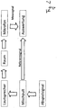
- Fig. 1 shows a schematic representation of an arrangement for determining an averaged frequency-dependent transfer function for a disturbed linear time invariant system.
- measuring signals are detected for a linear time-invariant system 1 with the aid of a measuring device 2 and applied to an evaluation device 3.
- the measurement signals received via an input 4 are respectively associated with associated reference signals which are provided in the evaluation device 3 for an excitation source 5.
- the determination of the frequency-dependent transfer function for the linear time-invariant system 1 takes place by means of evaluation of the received measurement and reference signals. The result is provided at an output 6.
- an averaging for the particular transfer functions takes place, such that during a measurement for the linear time-invariant system 1, a currently determined transfer function is averaged with an existing average value for the transfer functions.
- This averaging process includes the currently determined transfer function a frequency-dependent weighting.
- the evaluation device 3 in the illustrated embodiment has a threshold value filter 7, an excursion filter 8 and a coherence filter 9. As shown in FIG Fig. 1 In conjunction with a frequency-dependent transfer function, one, two or all three filters can be used.
- the time signal of an input channel is transformed block by block into the frequency domain. If the input spectrum is to be analyzed directly, these blocks are directly averaged after the Fourier transformation. When calculating a transfer function, there is no averaging of the input spectra.
- the now frequency-dependent data are subjected to a logical filter in both cases mentioned above, which in the simplest case requires a frequency-dependent minimum amplitude, ie the exceeding of a threshold value. Amplitude values of a frequency that do not reach this threshold are thus excluded from the averaging or further processing. In practice, this is realized, for example, so that the user first measures the interference spectrum at the input channel and then uses it as a comparison variable. In this case, a signal-to-noise ratio is typically specified, thus defines the signal amplitude frequency dependent, which must be achieved so that the respective measurement is in turn further processed frequency dependent.
- G (f j ) represents the threshold function defined as the amplitude G for the frequency f j .
- the comparison does not necessarily have to include only the amount, but can also be defined on the basis of real and imaginary part or another mathematical metric.
- N (f j ) one will define G as the sum of this spectrum and a possibly frequency-dependent signal-to-noise ratio D (f j ), which must at least be maintained:
- G f j N f j + D f j
- a dynamic range B which excludes the measured value for a frequency, for example, depending on the maximum or average signal amplitude over the entire or a partial frequency range of the respective block, if this is too low.
- the threshold value filter is in principle designed so that it removes all permanently existing components from the input signal, which are not caused by the excitation signal and are also present in the unexcited state of the system to be measured.
- a so-called “excursion filter” is used in this design, which filters out short-term, high-level interferences from the measurement. This filter is already applied after the calculation of the transfer function from the input signals.
- the transfer function is defined as a spectral function, which results from the deployment of two input signals.
- the excursion filter assumes that already knowledge about the transfer function exists, whether from assumptions or previous measurements.
- the invention now involves the use of a further filter, which is particularly important for averaging over several measurements of the transfer function mentioned above.
- a continuous weight function W (f j ) can be used, which is of particular interest in the ongoing averaging.
- the new measured value H (f j ) enters the mean value H M (f j ) or H M new (f j ) only as a function of its deviation from the comparison value H 0 :
- H M New f j c , H M f j + H f j , W f j
- c represents an insignificant standardization constant for averaging for our purposes.
- This implementation would correspond, for example, to a Tukey window, based on the amplitude difference from the comparison value.
- the excursion filter is defined so that it removes measured values, possibly frequency-dependent, which occur for a short time and deviate greatly from the expected value. At the same time, it must be ensured that, when applied in a real-time measurement, a slowly changing system can possibly also be followed, ie permanent changes in the transfer function can not be ruled out, but can be absorbed with a well-defined inertia.
- a further filter is formed which, in determining the averaged transfer function, evaluates measurement signals based on the coherence.
- the statistical measure of coherence is used to determine the linear dependence of two input signals on each other. This is a crucial prerequisite for determining the linear transfer function by deconvolution. Based on the coherence, the measured values are then either discarded or reused.
- other measures similar to the coherence can be used to determine the linear dependence of the two input signals, for example cross-correlation.
- the mean value function ⁇ ..> defines the mean value over several measured blocks of raw data.
- the weighting function may also be defined continuously, thus further processing measured values as a function of and weighted with the respective size of their coherence.
- this third filter ensures that short-term disturbances that are not correlated with the excitation signal are excluded from the measurement result in the amplitude range of the excitation signal.
- it is usually necessary to precede the excursion filter described above, since with very large signal amplitudes the current measured value H (f j ) dominates the coherence and can thus greatly falsify the entire measurement.
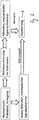
- FIG. 2 to 7 Schematic diagrams are shown for arrangements for determining an averaged frequency-dependent transfer function for a linear time invariant system in connection with various application examples. So shows Fig. 2 this for a real-time acoustic measurement.
- Fig. 3 refers to an electrical test measurement.
- the Fig. 4 and 5 concern an oceanographic measurement and an acoustic tomography.
- the concern Fig. 6 and 7 a geological measurement and a climatological measurement.
- the determination of the averaged transfer function can be carried out in real time.
- the inputs of the evaluation device are evaluated while additional data is received at the input in parallel.
- Inputs are analogue or digital as data and are played in the measuring system.
- the filtering can be subordinate to the recording of the raw data independently of time.
- measured raw data are typically first converted into an electrical signal, digitized and recorded.
- the actual evaluation is then carried out by reading in or playing in an evaluation device.
- the asynchronicity of this process has some advantages in practice. For example, an optimization of evaluation parameters is better possible, since the available local time is usually limited at the time of a measurement.
- the evaluation process can be repeated by reading in the data again with different evaluation parameters, whereas, on the spot, individual events in the raw data can not, of course, be reproduced at the time of the data acquisition.
- the direct on-site evaluation is impossible due to local conditions (measurement at the South Pole or the like) or time scales (years in oceanography).
- the method for determining the averaged transfer function in one of the previously described embodiments can be used, for example, in conjunction with the real-time acoustic measurement in the occupied stadium (cf. Fig. 2 ).
- Output signal is an arbitrary broadband audio signal for the transfer function to be determined. It is output from the mixer via the amplifiers and speakers in the stadium.
- the reference signal is obtained electrically from the mixer and played on the computer via A / D converter.
- the measuring signal is obtained electrically from the microphone in the stadium, picks up the acoustic signal at the receiving point.
- the measuring chain thus includes speakers, transmission path in the stadium and microphone.
- the input signals are in each case electrical (U in V), but can also be understood individually or together acoustically (p in Pa) if microphone or loudspeakers are calibrated (Pa / V or V / Pa).
- Related embodiments relate to the measurement of a loudspeaker in the laboratory for the purpose of loudspeaker development, room acoustic measurements, for example in theaters, churches, railway stations, or automated test measurements of voice alarm systems.
- the method for determining the averaged transfer function in one of the previously described embodiments can furthermore be used in conjunction with an electrical test measurement (cf. Fig. 3 ), for example in line monitoring of electro-acoustic and electrical systems.
- Output signal is an arbitrary broadband playback signal for the transfer function to be determined. It is output from the central unit via the amplifiers and speakers in the stadium.
- the reference signal is obtained electrically from the central unit and played via A / D converter to the computer.
- the measurement signal for the linear time invariant system is obtained electrically from the output of the electrical reproduction chain, typically removed behind the amplifier and in front of the loudspeaker.
- the The measuring chain thus includes the entire electrical transmission path on the output side.
- the measured variables of the inputs are each electrical (U in V).
- Related embodiments relate to a test measurement or tuning of a DSP controller or the impedance measurement of the electrical reproduction chain.
- the method for determining the averaged transfer function in one of the embodiments described above can also be used, for example, in connection with oceanography (cf. Fig. 4 ), for example, in the determination of spatial and temporal response functions, such as water level of the Baltic Sea as a response function of wind direction and strength, which will be explained below.
- the reference signal is the measured wind strength components North and East in the area of the Danish roads (Sund and Belte), for example Cape Arkona, measuring station of the DWD (German Weather Service). Measuring signal is the water level of the SMHI near Landsort, Sweden. The signals are converted from mechanical to electrical quantities and recorded hourly, later processed. The result is the dependence of the landing-site level as a response function of the Baltic Sea on the north and the east component of the wind vector in the Danish roads. Typical length of the answer function is 10 days.
- the measuring chain includes the mechanical signal sensor for wind direction and speed, which are converted into an electrical signal, digitized and recorded. Similarly, the measurement of the water level is performed and recorded.
- the method for determining the averaged transfer function in one of the previously described embodiments can also be used in conjunction with acoustic tomography (cf. Fig. 5 ), ie the measurement of the temperature distribution in oceans by means of low-frequency acoustic signals.
- the reference signal here is an excitation signal recorded via an underwater loudspeaker.
- Measurement signal is the response of the ocean to the excitation taken by an underwater measurement microphone.
- Inputs of the evaluation device are each electrical (U in V), but can also be understood individually or together acoustically (p in Pa) when microphone or speakers are calibrated (Pa / V or V / Pa). The evaluation can be carried out in real time or subsequently separately.
- the method for determining the averaged transfer function in one of the embodiments described above can be used in conjunction with geology (cf. Fig. 6 ), ie the determination of the position, the thickness, the structure and the dimensions of shells / layers in the Earth's interior.
- Reference signal is an acoustic, locally recorded excitation signal, often triggered, for example, by blasts, subterranean nuclear explosions or earthquakes.
- Measurement signal is an acoustically recorded signal at distant reception locations. The response functions of different measuring locations result in a three-dimensional response function to the selective excitation. From this conclusions about the structure of the Earth's interior can be drawn. Inputs are each electrical (U in V), but can also be understood individually or together acoustically (p in Pa) or mechanically (F in N), depending on the calibration of the signal sensor.
- Another embodiment relates to climatology, for example the measurement of the effect of changes in the radiation intensity of the sun on climatological variables such as precipitation (cf. Fig. 7 ).
- Reference signal here is the measured modulation of the radiation intensity of the sun, preferably by a satellite. This is typically significantly influenced by the sunspot cycle. Measuring signal is the precipitation series for St. Helena in the South Atlantic, recorded in mm on a monthly average. The result is the dependence of precipitation as a response to the variation of solar radiation, or the significance of sunspots. Inputs are available after conversion of the intensity or amount of precipitation each electrical (U in V) and are recorded digitally. The evaluation is typically then carried out separately from the actual measurement.
Landscapes
- Physics & Mathematics (AREA)
- Engineering & Computer Science (AREA)
- Acoustics & Sound (AREA)
- Signal Processing (AREA)
- Measurement Of Mechanical Vibrations Or Ultrasonic Waves (AREA)
Claims (8)
- Procédé destiné à déterminer la moyenne d'une fonction de transmission dépendant de la fréquence pour un système linéaire défaillant, invariant dans le temps au moyen d'un dispositif d'évaluation (3), le procédé comprenant les étapes suivantes:- de la mise à disposition de signaux de référence dépendant de la fréquence sur une entrée du dispositif d'évaluation (3), sachant que les signaux de référence dépendant de la fréquence sont dérivés de signaux d'excitation appliqués sur un système linéaire invariant dans le temps,- de la mise à disposition de signaux de mesure dépendant de la fréquence sur l'entrée du dispositif d'évaluation (3), sachant que les signaux de mesure dépendant de la fréquence pour le système linéaire invariant dans le temps sont déterminés suite à une excitation du système linéaire invariant dans le temps, via les signaux d'excitation et sont associés aux signaux de référence dépendant de la fréquence et- de la détermination de la moyenne d'une fonction de transmission dépendant de la fréquence pour le système linéaire invariant dans le temps, en ce qu'en utilisant un déploiement de signaux de mesure et de référence réciproquement associés, on détermine par blocs à partir des signaux de mesure et de référence dépendant de la fréquence des fonctions de transmission dépendant de la fréquence, de telle sorte qu'à partir d'un bloc de signaux de mesure et de référence réciproquement associés, il soit déterminé chaque fois une fonction de transmission et que la moyenne des fonctions de transmission dépendant de la fréquence soit calculée,lors de la détermination de la moyenne de la fonction de transmission dépendant de la fréquence, au moins une partie des fonctions de transmission dépendant de la fréquence déterminées étant prise en compte dans le calcul de la moyenne, conformément à une pondération respectivement associée.
- Procédé selon la revendication 1, caractérisé en ce que lors de la détermination de la moyenne de la fonction de transmission dépendant de la fréquence, on calcule la moyenne d'une fonction de transmission dépendant de la fréquence existante et d'une fonction de transmission dépendant de la fréquence actuellement déterminée, sachant que la fonction de transmission dépendant de la fréquence actuellement déterminée est prise en compte dans le calcul de la moyenne, conformément à la pondération dépendant de la fréquence associée.
- Procédé selon la revendication 1 ou 2, caractérisé en ce qu'on pondère l'au moins une partie de la fonction de transmission dépendant de la fréquence déterminée chaque fois conformément à une fonction de valeur seuil dépendant de la fréquence.
- Procédé selon au moins l'une quelconque des revendications précédentes, dans la mesure où elle se réfère à la revendication 2, caractérisé en ce qu'on pondère l'au moins une partie des plusieurs fonctions de transmission dépendant de la fréquence chaque fois conformément à une fonction d'écart métrique dépendant de la fréquence, sachant que la fonction d'écart métrique indique la pondération dépendant de la fréquence en fonction d'un écart métrique entre la fonction de transmission dépendant de la fréquence existante dont on a calculé la moyenne et la fonction de transmission dépendant de la fréquence actuellement déterminée.
- Procédé selon au moins l'une quelconque des revendications précédentes, caractérisé en ce qu'on pondère l'au moins une partie de la fonction de transmission dépendant de la fréquence déterminée chaque fois conformément à une fonction de corrélation dépendant de la fréquence, sachant que la fonction de corrélation indique la pondération dépendant de la fréquence pour une fonction de transmission dépendant de la fréquence, en fonction d'une corrélation entre le signal de référence dépendant de la fréquence et le signal de mesure dépendant de la fréquence associé, à partir desquels la fonction de transmission dépendant de la fréquence est déterminée.
- Procédé selon au moins l'une quelconque des revendications précédentes, caractérisé en ce qu'on détermine la moyenne de la fonction de transmission dépendant de la fréquence dans le cadre d'une mesure en temps réel pour le système linéaire invariant dans le temps.
- Dispositif d'évaluation destiné à déterminer la moyenne d'une fonction de transmission dépendant de la fréquence pour un système linéaire défaillant, invariant dans le temps, avec :- plusieurs canaux d'entrée qui sont configurés pour réceptionner des signaux de référence dépendant de la fréquence, qui sont dérivés de signaux d'excitation appliqués sur un système linéaire invariant dans le temps et des signaux de mesure dépendant de la fréquence qui sont déterminés pour le système linéaire invariant dans le temps, suite à une excitation du système linéaire invariant dans le temps à l'aide des signaux d'excitation et qui sont associés aux signaux de référence dépendant de la fréquence,- une unité d'évaluation qui est couplée sur les plusieurs canaux d'entrée et qui est configurée pour déterminer la moyenne d'une fonction de transmission dépendant de la fréquence pour le système linéaire invariant dans le temps en ce qu'en utilisant un déploiement de signaux de mesure et de référence réciproquement associés à partir des signaux de mesure et de référence dépendant de la fréquence, des fonctions de transmission dépendant de la fréquence sont déterminées par blocs, de telle sorte qu'à partir d'un bloc de signaux de mesure et de référence réciproquement associés, il est déterminé chaque fois une fonction de transmission et en ce que la moyenne des fonctions de transmission dépendant de la fréquence est calculée, sachant que lors de la détermination de la moyenne des fonctions de transmission dépendant de la fréquence, au moins une partie des fonctions de transmission dépendant de la fréquence déterminées est prise en compte dans le calcul de la moyenne conformément à une pondération dépendant de la fréquence respectivement associée.
- Produit de programme informatique avec un code programme qui est mémorisé au choix sur un milieu de mémoire lisible par ordinateur et qui est adapté, lors de l'exécution sur un dispositif informatique pour réaliser un procédé selon l'une quelconque des revendications 1 à 6.
Applications Claiming Priority (2)
| Application Number | Priority Date | Filing Date | Title |
|---|---|---|---|
| DE102009025117 | 2009-06-11 | ||
| PCT/DE2010/000571 WO2010142262A1 (fr) | 2009-06-11 | 2010-05-21 | Procédé permettant de déterminer une fonction de transmission moyenne dépendant de la fréquence pour un système linéaire perturbé invariant dans le temps, dispositif d'évaluation et produit-programme informatique |
Publications (2)
| Publication Number | Publication Date |
|---|---|
| EP2441274A1 EP2441274A1 (fr) | 2012-04-18 |
| EP2441274B1 true EP2441274B1 (fr) | 2017-08-09 |
Family
ID=42739888
Family Applications (1)
| Application Number | Title | Priority Date | Filing Date |
|---|---|---|---|
| EP10730695.3A Not-in-force EP2441274B1 (fr) | 2009-06-11 | 2010-05-21 | Procédé de détermination d'une fonction de transfert à moyenne dépendant de la fréquence pour un système d'invariance de temps linéaire (lti) perturbé, unité d'évaluation et programme d'ordinateur |
Country Status (3)
| Country | Link |
|---|---|
| US (1) | US9060222B2 (fr) |
| EP (1) | EP2441274B1 (fr) |
| WO (1) | WO2010142262A1 (fr) |
Families Citing this family (7)
| Publication number | Priority date | Publication date | Assignee | Title |
|---|---|---|---|---|
| FR3034274B1 (fr) | 2015-03-27 | 2017-03-24 | Stmicroelectronics Rousset | Procede de traitement d'un signal analogique issu d'un canal de transmission, en particulier un signal vehicule par courant porteur en ligne |
| FR3038801B1 (fr) * | 2015-07-09 | 2017-07-21 | Stmicroelectronics Rousset | Procede d'estimation d'un canal de transmission temporellement invariant, et recepteur correspondant |
| FR3038800A1 (fr) | 2015-07-09 | 2017-01-13 | Stmicroelectronics Rousset | Procede de traitement d'un signal issu d'un canal de transmission, en particulier un signal vehicule par courant porteur en ligne, et notamment l'estimation du canal, et recepteur correspondant |
| US9838077B2 (en) | 2015-07-09 | 2017-12-05 | Stmicroelectronics (Rousset) Sas | Method for estimating a cyclostationary transmission channel, and corresponding receiver |
| CN105861811B (zh) * | 2016-04-28 | 2018-02-02 | 上海海事大学 | 一种振动时效效果的在线定量化评价系统及方法 |
| EP3396398B1 (fr) * | 2017-04-27 | 2020-07-08 | Rohde & Schwarz GmbH & Co. KG | Procédé de correction de signal, système permettant de corriger un signal mesuré ainsi qu'un oscilloscope |
| DE102020215960A1 (de) * | 2020-01-31 | 2021-08-05 | Carl Zeiss Industrielle Messtechnik Gmbh | Verfahren und Anordnung zum Ermitteln einer Position eines Objekts |
Family Cites Families (4)
| Publication number | Priority date | Publication date | Assignee | Title |
|---|---|---|---|---|
| DE2313141A1 (de) | 1973-03-16 | 1974-09-19 | Philips Patentverwaltung | Verfahren und anordnung zur echtzeitermittlung der uebertragungsfunktionen von systemen |
| NL8300671A (nl) * | 1983-02-23 | 1984-09-17 | Philips Nv | Automatisch egalisatiesysteem met dtf of fft. |
| JPH0739968B2 (ja) | 1991-03-25 | 1995-05-01 | 日本電信電話株式会社 | 音響伝達特性模擬方法 |
| DE102006004105A1 (de) | 2006-01-28 | 2007-08-02 | Conti Temic Microelectronic Gmbh | Vorrichtung und Verfahren zur Messgrößenaufbereitung |
-
2010
- 2010-05-21 WO PCT/DE2010/000571 patent/WO2010142262A1/fr not_active Ceased
- 2010-05-21 EP EP10730695.3A patent/EP2441274B1/fr not_active Not-in-force
- 2010-05-21 US US13/377,215 patent/US9060222B2/en not_active Expired - Fee Related
Non-Patent Citations (1)
| Title |
|---|
| BROERSEN, P.: "A comparison of transfer function estimators", IEEE TRANSACTIONS ON INSTRUMENTATION AND MEASUREMENT, vol. 44, no. 3, 3 June 1995 (1995-06-03), pages 657 - 661, XP010121750 * |
Also Published As
| Publication number | Publication date |
|---|---|
| EP2441274A1 (fr) | 2012-04-18 |
| US20120143553A1 (en) | 2012-06-07 |
| WO2010142262A1 (fr) | 2010-12-16 |
| US9060222B2 (en) | 2015-06-16 |
Similar Documents
| Publication | Publication Date | Title |
|---|---|---|
| DE102013022403B3 (de) | Sensorsystem zur akustischen Vermessung der Eigenschaften einer Übertragungsstrecke eines Messsystems zwischen Lautsprecher und Mikrofon | |
| EP2441274B1 (fr) | Procédé de détermination d'une fonction de transfert à moyenne dépendant de la fréquence pour un système d'invariance de temps linéaire (lti) perturbé, unité d'évaluation et programme d'ordinateur | |
| DE102007031677B4 (de) | Verfahren und Vorrichtung zum Ermitteln einer raumakustischen Impulsantwort in der Zeitdomäne | |
| DE602004001241T2 (de) | Vorrichtung zur Unterdrückung von impulsartigen Windgeräuschen | |
| DE112016006218B4 (de) | Schallsignal-Verbesserungsvorrichtung | |
| DE102016003133B4 (de) | Verfahren zur automatischen Bestimmung einer individuellen Funktion einer DPOAE-Pegelkarte eines menschlichen oder tierischen Gehörs | |
| DE102017215825B3 (de) | Verfahren zum Erkennen eines Defektes in einem Hörinstrument | |
| DE102015220092B3 (de) | Verfahren zur Bestimmung einer räumlichen Zuordnung oder räumlichen Verteilung von Magnetpartikeln | |
| DE10214407C1 (de) | Anordnung und Verfahren zur Messung, Bewertung und Störungserkennung von Systemen | |
| EP2070388A2 (fr) | Procédé et dispositif de mesure pour le contrôle de systèmes de sonorisation | |
| AT510359B1 (de) | Verfahren zur akustischen signalverfolgung | |
| EP3929600A1 (fr) | Procédé de détection par ultrasons large bande des décharges électriques | |
| DE102014204665B4 (de) | Geräuschoptimierung einer Magnetresonanzanlage | |
| EP3132282A1 (fr) | Dispositif et procédé de détection sonore d'un environnement | |
| WO1998006196A1 (fr) | Procede et dispositif pour evaluer la qualite d'un signal vocal transmis | |
| EP1209458B1 (fr) | Procédé permettant de déterminer le niveau de bruit d'un moteur à combustion interne | |
| EP1401243B1 (fr) | Méthode pour l'optimisation d'un signal audio | |
| DE112022003614T5 (de) | Doppelseitiges Zwei-Wege-Abstandsmessungsprotokoll auf Grundlage von zusammengesetzten Ultraschalltönen | |
| WO2003016927A1 (fr) | Procede et dispositif pour determiner la courbe spectrale de signaux electromagnetiques a l'interieur d'une gamme de frequences | |
| DE102024100423B3 (de) | Verfahren zur Audiobearbeitung eines durch ein Mikrofon erfassten Audiosignals | |
| EP3217392B1 (fr) | Audibilité de signaux ultrasonores à large bande | |
| DE102022004472A1 (de) | Verfahren zum Kalibrieren eines Multimikrofonsystems | |
| DE102007045858B4 (de) | Verfahren und System zum Bestimmen eines Amplitudengangs | |
| DE102006007779B4 (de) | Filterbank-Anordnung und Signalverarbeitungs-Vorrichtung | |
| DE102013021904B4 (de) | Reduzierung in Echtzeit von Audio-Echo und Hintergrundgeräuschen für ein Mobilgerät |
Legal Events
| Date | Code | Title | Description |
|---|---|---|---|
| PUAI | Public reference made under article 153(3) epc to a published international application that has entered the european phase |
Free format text: ORIGINAL CODE: 0009012 |
|
| 17P | Request for examination filed |
Effective date: 20120109 |
|
| AK | Designated contracting states |
Kind code of ref document: A1 Designated state(s): AL AT BE BG CH CY CZ DE DK EE ES FI FR GB GR HR HU IE IS IT LI LT LU LV MC MK MT NL NO PL PT RO SE SI SK SM TR |
|
| DAX | Request for extension of the european patent (deleted) | ||
| 17Q | First examination report despatched |
Effective date: 20151218 |
|
| GRAJ | Information related to disapproval of communication of intention to grant by the applicant or resumption of examination proceedings by the epo deleted |
Free format text: ORIGINAL CODE: EPIDOSDIGR1 |
|
| GRAP | Despatch of communication of intention to grant a patent |
Free format text: ORIGINAL CODE: EPIDOSNIGR1 |
|
| INTG | Intention to grant announced |
Effective date: 20170306 |
|
| GRAS | Grant fee paid |
Free format text: ORIGINAL CODE: EPIDOSNIGR3 |
|
| GRAA | (expected) grant |
Free format text: ORIGINAL CODE: 0009210 |
|
| AK | Designated contracting states |
Kind code of ref document: B1 Designated state(s): AL AT BE BG CH CY CZ DE DK EE ES FI FR GB GR HR HU IE IS IT LI LT LU LV MC MK MT NL NO PL PT RO SE SI SK SM TR |
|
| REG | Reference to a national code |
Ref country code: GB Ref legal event code: FG4D Free format text: NOT ENGLISH |
|
| REG | Reference to a national code |
Ref country code: CH Ref legal event code: EP Ref country code: AT Ref legal event code: REF Ref document number: 918022 Country of ref document: AT Kind code of ref document: T Effective date: 20170815 |
|
| REG | Reference to a national code |
Ref country code: IE Ref legal event code: FG4D Free format text: LANGUAGE OF EP DOCUMENT: GERMAN |
|
| REG | Reference to a national code |
Ref country code: DE Ref legal event code: R096 Ref document number: 502010013985 Country of ref document: DE |
|
| REG | Reference to a national code |
Ref country code: NL Ref legal event code: MP Effective date: 20170809 |
|
| REG | Reference to a national code |
Ref country code: LT Ref legal event code: MG4D |
|
| PG25 | Lapsed in a contracting state [announced via postgrant information from national office to epo] |
Ref country code: SE Free format text: LAPSE BECAUSE OF FAILURE TO SUBMIT A TRANSLATION OF THE DESCRIPTION OR TO PAY THE FEE WITHIN THE PRESCRIBED TIME-LIMIT Effective date: 20170809 Ref country code: HR Free format text: LAPSE BECAUSE OF FAILURE TO SUBMIT A TRANSLATION OF THE DESCRIPTION OR TO PAY THE FEE WITHIN THE PRESCRIBED TIME-LIMIT Effective date: 20170809 Ref country code: NL Free format text: LAPSE BECAUSE OF FAILURE TO SUBMIT A TRANSLATION OF THE DESCRIPTION OR TO PAY THE FEE WITHIN THE PRESCRIBED TIME-LIMIT Effective date: 20170809 Ref country code: NO Free format text: LAPSE BECAUSE OF FAILURE TO SUBMIT A TRANSLATION OF THE DESCRIPTION OR TO PAY THE FEE WITHIN THE PRESCRIBED TIME-LIMIT Effective date: 20171109 Ref country code: LT Free format text: LAPSE BECAUSE OF FAILURE TO SUBMIT A TRANSLATION OF THE DESCRIPTION OR TO PAY THE FEE WITHIN THE PRESCRIBED TIME-LIMIT Effective date: 20170809 Ref country code: FI Free format text: LAPSE BECAUSE OF FAILURE TO SUBMIT A TRANSLATION OF THE DESCRIPTION OR TO PAY THE FEE WITHIN THE PRESCRIBED TIME-LIMIT Effective date: 20170809 |
|
| PG25 | Lapsed in a contracting state [announced via postgrant information from national office to epo] |
Ref country code: PL Free format text: LAPSE BECAUSE OF FAILURE TO SUBMIT A TRANSLATION OF THE DESCRIPTION OR TO PAY THE FEE WITHIN THE PRESCRIBED TIME-LIMIT Effective date: 20170809 Ref country code: ES Free format text: LAPSE BECAUSE OF FAILURE TO SUBMIT A TRANSLATION OF THE DESCRIPTION OR TO PAY THE FEE WITHIN THE PRESCRIBED TIME-LIMIT Effective date: 20170809 Ref country code: IS Free format text: LAPSE BECAUSE OF FAILURE TO SUBMIT A TRANSLATION OF THE DESCRIPTION OR TO PAY THE FEE WITHIN THE PRESCRIBED TIME-LIMIT Effective date: 20171209 Ref country code: LV Free format text: LAPSE BECAUSE OF FAILURE TO SUBMIT A TRANSLATION OF THE DESCRIPTION OR TO PAY THE FEE WITHIN THE PRESCRIBED TIME-LIMIT Effective date: 20170809 Ref country code: GR Free format text: LAPSE BECAUSE OF FAILURE TO SUBMIT A TRANSLATION OF THE DESCRIPTION OR TO PAY THE FEE WITHIN THE PRESCRIBED TIME-LIMIT Effective date: 20171110 Ref country code: BG Free format text: LAPSE BECAUSE OF FAILURE TO SUBMIT A TRANSLATION OF THE DESCRIPTION OR TO PAY THE FEE WITHIN THE PRESCRIBED TIME-LIMIT Effective date: 20171109 |
|
| PG25 | Lapsed in a contracting state [announced via postgrant information from national office to epo] |
Ref country code: CZ Free format text: LAPSE BECAUSE OF FAILURE TO SUBMIT A TRANSLATION OF THE DESCRIPTION OR TO PAY THE FEE WITHIN THE PRESCRIBED TIME-LIMIT Effective date: 20170809 Ref country code: DK Free format text: LAPSE BECAUSE OF FAILURE TO SUBMIT A TRANSLATION OF THE DESCRIPTION OR TO PAY THE FEE WITHIN THE PRESCRIBED TIME-LIMIT Effective date: 20170809 Ref country code: RO Free format text: LAPSE BECAUSE OF FAILURE TO SUBMIT A TRANSLATION OF THE DESCRIPTION OR TO PAY THE FEE WITHIN THE PRESCRIBED TIME-LIMIT Effective date: 20170809 |
|
| REG | Reference to a national code |
Ref country code: DE Ref legal event code: R097 Ref document number: 502010013985 Country of ref document: DE |
|
| REG | Reference to a national code |
Ref country code: FR Ref legal event code: PLFP Year of fee payment: 9 |
|
| PG25 | Lapsed in a contracting state [announced via postgrant information from national office to epo] |
Ref country code: SM Free format text: LAPSE BECAUSE OF FAILURE TO SUBMIT A TRANSLATION OF THE DESCRIPTION OR TO PAY THE FEE WITHIN THE PRESCRIBED TIME-LIMIT Effective date: 20170809 Ref country code: EE Free format text: LAPSE BECAUSE OF FAILURE TO SUBMIT A TRANSLATION OF THE DESCRIPTION OR TO PAY THE FEE WITHIN THE PRESCRIBED TIME-LIMIT Effective date: 20170809 Ref country code: IT Free format text: LAPSE BECAUSE OF FAILURE TO SUBMIT A TRANSLATION OF THE DESCRIPTION OR TO PAY THE FEE WITHIN THE PRESCRIBED TIME-LIMIT Effective date: 20170809 Ref country code: SK Free format text: LAPSE BECAUSE OF FAILURE TO SUBMIT A TRANSLATION OF THE DESCRIPTION OR TO PAY THE FEE WITHIN THE PRESCRIBED TIME-LIMIT Effective date: 20170809 |
|
| PLBE | No opposition filed within time limit |
Free format text: ORIGINAL CODE: 0009261 |
|
| STAA | Information on the status of an ep patent application or granted ep patent |
Free format text: STATUS: NO OPPOSITION FILED WITHIN TIME LIMIT |
|
| 26N | No opposition filed |
Effective date: 20180511 |
|
| PG25 | Lapsed in a contracting state [announced via postgrant information from national office to epo] |
Ref country code: SI Free format text: LAPSE BECAUSE OF FAILURE TO SUBMIT A TRANSLATION OF THE DESCRIPTION OR TO PAY THE FEE WITHIN THE PRESCRIBED TIME-LIMIT Effective date: 20170809 |
|
| PG25 | Lapsed in a contracting state [announced via postgrant information from national office to epo] |
Ref country code: MT Free format text: LAPSE BECAUSE OF FAILURE TO SUBMIT A TRANSLATION OF THE DESCRIPTION OR TO PAY THE FEE WITHIN THE PRESCRIBED TIME-LIMIT Effective date: 20170809 |
|
| REG | Reference to a national code |
Ref country code: CH Ref legal event code: PL |
|
| REG | Reference to a national code |
Ref country code: BE Ref legal event code: MM Effective date: 20180531 |
|
| PG25 | Lapsed in a contracting state [announced via postgrant information from national office to epo] |
Ref country code: MC Free format text: LAPSE BECAUSE OF FAILURE TO SUBMIT A TRANSLATION OF THE DESCRIPTION OR TO PAY THE FEE WITHIN THE PRESCRIBED TIME-LIMIT Effective date: 20170809 |
|
| REG | Reference to a national code |
Ref country code: IE Ref legal event code: MM4A |
|
| PG25 | Lapsed in a contracting state [announced via postgrant information from national office to epo] |
Ref country code: CH Free format text: LAPSE BECAUSE OF NON-PAYMENT OF DUE FEES Effective date: 20180531 Ref country code: LI Free format text: LAPSE BECAUSE OF NON-PAYMENT OF DUE FEES Effective date: 20180531 |
|
| PG25 | Lapsed in a contracting state [announced via postgrant information from national office to epo] |
Ref country code: LU Free format text: LAPSE BECAUSE OF NON-PAYMENT OF DUE FEES Effective date: 20180521 |
|
| PG25 | Lapsed in a contracting state [announced via postgrant information from national office to epo] |
Ref country code: IE Free format text: LAPSE BECAUSE OF NON-PAYMENT OF DUE FEES Effective date: 20180521 |
|
| PG25 | Lapsed in a contracting state [announced via postgrant information from national office to epo] |
Ref country code: BE Free format text: LAPSE BECAUSE OF NON-PAYMENT OF DUE FEES Effective date: 20180531 |
|
| REG | Reference to a national code |
Ref country code: AT Ref legal event code: MM01 Ref document number: 918022 Country of ref document: AT Kind code of ref document: T Effective date: 20180521 |
|
| PGFP | Annual fee paid to national office [announced via postgrant information from national office to epo] |
Ref country code: FR Payment date: 20190521 Year of fee payment: 10 |
|
| PG25 | Lapsed in a contracting state [announced via postgrant information from national office to epo] |
Ref country code: AT Free format text: LAPSE BECAUSE OF NON-PAYMENT OF DUE FEES Effective date: 20180521 |
|
| PGFP | Annual fee paid to national office [announced via postgrant information from national office to epo] |
Ref country code: GB Payment date: 20190523 Year of fee payment: 10 |
|
| PG25 | Lapsed in a contracting state [announced via postgrant information from national office to epo] |
Ref country code: TR Free format text: LAPSE BECAUSE OF FAILURE TO SUBMIT A TRANSLATION OF THE DESCRIPTION OR TO PAY THE FEE WITHIN THE PRESCRIBED TIME-LIMIT Effective date: 20170809 |
|
| PG25 | Lapsed in a contracting state [announced via postgrant information from national office to epo] |
Ref country code: HU Free format text: LAPSE BECAUSE OF FAILURE TO SUBMIT A TRANSLATION OF THE DESCRIPTION OR TO PAY THE FEE WITHIN THE PRESCRIBED TIME-LIMIT; INVALID AB INITIO Effective date: 20100521 Ref country code: PT Free format text: LAPSE BECAUSE OF FAILURE TO SUBMIT A TRANSLATION OF THE DESCRIPTION OR TO PAY THE FEE WITHIN THE PRESCRIBED TIME-LIMIT Effective date: 20170809 |
|
| PG25 | Lapsed in a contracting state [announced via postgrant information from national office to epo] |
Ref country code: MK Free format text: LAPSE BECAUSE OF NON-PAYMENT OF DUE FEES Effective date: 20170809 Ref country code: CY Free format text: LAPSE BECAUSE OF FAILURE TO SUBMIT A TRANSLATION OF THE DESCRIPTION OR TO PAY THE FEE WITHIN THE PRESCRIBED TIME-LIMIT Effective date: 20170809 |
|
| PG25 | Lapsed in a contracting state [announced via postgrant information from national office to epo] |
Ref country code: AL Free format text: LAPSE BECAUSE OF FAILURE TO SUBMIT A TRANSLATION OF THE DESCRIPTION OR TO PAY THE FEE WITHIN THE PRESCRIBED TIME-LIMIT Effective date: 20170809 |
|
| GBPC | Gb: european patent ceased through non-payment of renewal fee |
Effective date: 20200521 |
|
| PG25 | Lapsed in a contracting state [announced via postgrant information from national office to epo] |
Ref country code: GB Free format text: LAPSE BECAUSE OF NON-PAYMENT OF DUE FEES Effective date: 20200521 Ref country code: FR Free format text: LAPSE BECAUSE OF NON-PAYMENT OF DUE FEES Effective date: 20200531 |
|
| PGFP | Annual fee paid to national office [announced via postgrant information from national office to epo] |
Ref country code: DE Payment date: 20220531 Year of fee payment: 13 |
|
| REG | Reference to a national code |
Ref country code: DE Ref legal event code: R119 Ref document number: 502010013985 Country of ref document: DE |
|
| PG25 | Lapsed in a contracting state [announced via postgrant information from national office to epo] |
Ref country code: DE Free format text: LAPSE BECAUSE OF NON-PAYMENT OF DUE FEES Effective date: 20231201 |