EP2442037B1 - Procédé de réglage d'une installation de chauffage - Google Patents
Procédé de réglage d'une installation de chauffage Download PDFInfo
- Publication number
- EP2442037B1 EP2442037B1 EP10013541.7A EP10013541A EP2442037B1 EP 2442037 B1 EP2442037 B1 EP 2442037B1 EP 10013541 A EP10013541 A EP 10013541A EP 2442037 B1 EP2442037 B1 EP 2442037B1
- Authority
- EP
- European Patent Office
- Prior art keywords
- consumer
- collector
- temperature
- flow
- power
- Prior art date
- Legal status (The legal status is an assumption and is not a legal conclusion. Google has not performed a legal analysis and makes no representation as to the accuracy of the status listed.)
- Active
Links
Images


Classifications
-
- F—MECHANICAL ENGINEERING; LIGHTING; HEATING; WEAPONS; BLASTING
- F24—HEATING; RANGES; VENTILATING
- F24D—DOMESTIC- OR SPACE-HEATING SYSTEMS, e.g. CENTRAL HEATING SYSTEMS; DOMESTIC HOT-WATER SUPPLY SYSTEMS; ELEMENTS OR COMPONENTS THEREFOR
- F24D19/00—Details
- F24D19/10—Arrangement or mounting of control or safety devices
- F24D19/1006—Arrangement or mounting of control or safety devices for water heating systems
- F24D19/1009—Arrangement or mounting of control or safety devices for water heating systems for central heating
- F24D19/1015—Arrangement or mounting of control or safety devices for water heating systems for central heating using a valve or valves
-
- F—MECHANICAL ENGINEERING; LIGHTING; HEATING; WEAPONS; BLASTING
- F24—HEATING; RANGES; VENTILATING
- F24D—DOMESTIC- OR SPACE-HEATING SYSTEMS, e.g. CENTRAL HEATING SYSTEMS; DOMESTIC HOT-WATER SUPPLY SYSTEMS; ELEMENTS OR COMPONENTS THEREFOR
- F24D19/00—Details
- F24D19/0002—Means for connecting central heating radiators to circulation pipes
- F24D19/0004—In a one pipe system
- F24D19/0007—Comprising regulation means
-
- F—MECHANICAL ENGINEERING; LIGHTING; HEATING; WEAPONS; BLASTING
- F24—HEATING; RANGES; VENTILATING
- F24D—DOMESTIC- OR SPACE-HEATING SYSTEMS, e.g. CENTRAL HEATING SYSTEMS; DOMESTIC HOT-WATER SUPPLY SYSTEMS; ELEMENTS OR COMPONENTS THEREFOR
- F24D19/00—Details
- F24D19/10—Arrangement or mounting of control or safety devices
- F24D19/1006—Arrangement or mounting of control or safety devices for water heating systems
- F24D19/1009—Arrangement or mounting of control or safety devices for water heating systems for central heating
- F24D19/1012—Arrangement or mounting of control or safety devices for water heating systems for central heating by regulating the speed of a pump
-
- F—MECHANICAL ENGINEERING; LIGHTING; HEATING; WEAPONS; BLASTING
- F24—HEATING; RANGES; VENTILATING
- F24D—DOMESTIC- OR SPACE-HEATING SYSTEMS, e.g. CENTRAL HEATING SYSTEMS; DOMESTIC HOT-WATER SUPPLY SYSTEMS; ELEMENTS OR COMPONENTS THEREFOR
- F24D19/00—Details
- F24D19/10—Arrangement or mounting of control or safety devices
- F24D19/1006—Arrangement or mounting of control or safety devices for water heating systems
- F24D19/1009—Arrangement or mounting of control or safety devices for water heating systems for central heating
- F24D19/1015—Arrangement or mounting of control or safety devices for water heating systems for central heating using a valve or valves
- F24D19/1021—Arrangement or mounting of control or safety devices for water heating systems for central heating using a valve or valves a by pass valve
-
- F—MECHANICAL ENGINEERING; LIGHTING; HEATING; WEAPONS; BLASTING
- F24—HEATING; RANGES; VENTILATING
- F24D—DOMESTIC- OR SPACE-HEATING SYSTEMS, e.g. CENTRAL HEATING SYSTEMS; DOMESTIC HOT-WATER SUPPLY SYSTEMS; ELEMENTS OR COMPONENTS THEREFOR
- F24D19/00—Details
- F24D19/10—Arrangement or mounting of control or safety devices
- F24D19/1006—Arrangement or mounting of control or safety devices for water heating systems
- F24D19/1009—Arrangement or mounting of control or safety devices for water heating systems for central heating
- F24D19/1015—Arrangement or mounting of control or safety devices for water heating systems for central heating using a valve or valves
- F24D19/1024—Arrangement or mounting of control or safety devices for water heating systems for central heating using a valve or valves a multiple way valve
-
- F—MECHANICAL ENGINEERING; LIGHTING; HEATING; WEAPONS; BLASTING
- F24—HEATING; RANGES; VENTILATING
- F24D—DOMESTIC- OR SPACE-HEATING SYSTEMS, e.g. CENTRAL HEATING SYSTEMS; DOMESTIC HOT-WATER SUPPLY SYSTEMS; ELEMENTS OR COMPONENTS THEREFOR
- F24D19/00—Details
- F24D19/10—Arrangement or mounting of control or safety devices
- F24D19/1006—Arrangement or mounting of control or safety devices for water heating systems
- F24D19/1009—Arrangement or mounting of control or safety devices for water heating systems for central heating
- F24D19/1042—Arrangement or mounting of control or safety devices for water heating systems for central heating the system uses solar energy
-
- F—MECHANICAL ENGINEERING; LIGHTING; HEATING; WEAPONS; BLASTING
- F24—HEATING; RANGES; VENTILATING
- F24D—DOMESTIC- OR SPACE-HEATING SYSTEMS, e.g. CENTRAL HEATING SYSTEMS; DOMESTIC HOT-WATER SUPPLY SYSTEMS; ELEMENTS OR COMPONENTS THEREFOR
- F24D2200/00—Heat sources or energy sources
- F24D2200/14—Solar energy
-
- Y—GENERAL TAGGING OF NEW TECHNOLOGICAL DEVELOPMENTS; GENERAL TAGGING OF CROSS-SECTIONAL TECHNOLOGIES SPANNING OVER SEVERAL SECTIONS OF THE IPC; TECHNICAL SUBJECTS COVERED BY FORMER USPC CROSS-REFERENCE ART COLLECTIONS [XRACs] AND DIGESTS
- Y02—TECHNOLOGIES OR APPLICATIONS FOR MITIGATION OR ADAPTATION AGAINST CLIMATE CHANGE
- Y02B—CLIMATE CHANGE MITIGATION TECHNOLOGIES RELATED TO BUILDINGS, e.g. HOUSING, HOUSE APPLIANCES OR RELATED END-USER APPLICATIONS
- Y02B10/00—Integration of renewable energy sources in buildings
- Y02B10/20—Solar thermal
-
- Y—GENERAL TAGGING OF NEW TECHNOLOGICAL DEVELOPMENTS; GENERAL TAGGING OF CROSS-SECTIONAL TECHNOLOGIES SPANNING OVER SEVERAL SECTIONS OF THE IPC; TECHNICAL SUBJECTS COVERED BY FORMER USPC CROSS-REFERENCE ART COLLECTIONS [XRACs] AND DIGESTS
- Y02—TECHNOLOGIES OR APPLICATIONS FOR MITIGATION OR ADAPTATION AGAINST CLIMATE CHANGE
- Y02B—CLIMATE CHANGE MITIGATION TECHNOLOGIES RELATED TO BUILDINGS, e.g. HOUSING, HOUSE APPLIANCES OR RELATED END-USER APPLICATIONS
- Y02B10/00—Integration of renewable energy sources in buildings
- Y02B10/70—Hybrid systems, e.g. uninterruptible or back-up power supplies integrating renewable energies
-
- Y—GENERAL TAGGING OF NEW TECHNOLOGICAL DEVELOPMENTS; GENERAL TAGGING OF CROSS-SECTIONAL TECHNOLOGIES SPANNING OVER SEVERAL SECTIONS OF THE IPC; TECHNICAL SUBJECTS COVERED BY FORMER USPC CROSS-REFERENCE ART COLLECTIONS [XRACs] AND DIGESTS
- Y02—TECHNOLOGIES OR APPLICATIONS FOR MITIGATION OR ADAPTATION AGAINST CLIMATE CHANGE
- Y02B—CLIMATE CHANGE MITIGATION TECHNOLOGIES RELATED TO BUILDINGS, e.g. HOUSING, HOUSE APPLIANCES OR RELATED END-USER APPLICATIONS
- Y02B30/00—Energy efficient heating, ventilation or air conditioning [HVAC]
- Y02B30/70—Efficient control or regulation technologies, e.g. for control of refrigerant flow, motor or heating
Definitions
- the invention relates to a method for control, which is carried out in a system having a solar collector as a power source, a pump, a main line and at least one valve in a heating circuit and a plurality of consumers, wherein the main line is at least partially traversed by a fluid energy carrier medium, the power source is adapted to transmit a specific, in particular the maximum available, instantaneous power (power output) to the energy carrier medium, and the consumers each have a momentary power requirement (recording power).
- Such a plant is from the DE 4124304 A1 known.
- the known heating system several consumers with different temperature levels are connected to the heating circuit.
- a three-way valve by which at least a partial flow of the heating circuit can be directed to the consumer.
- the remaining partial flow flows through a bypass arranged parallel to the consumer and mixes with the return flow of the consumer and then flows to the next valve of another consumer.
- the interconnection of the second three-way valve and the further consumer with the heating circuit is analogous to the first consumer.
- any number of other consumers can be connected to the heating circuit.
- a fluid energy carrier medium of the heating circuit can therefore flow through the consumers in series and / or in parallel. Heat energy of the energy carrier medium, which is not delivered to the consumer, can preferably be forwarded with a partial flow from the bypass line to a downstream consumer with a lower temperature level. From the last consumer, the fluid energy medium flows back to the power source.
- the temperature of the energy carrier medium drops when flowing through a consumer.
- this consumer can be followed only those consumers who have a lower temperature level.
- the temperature of the energy carrier medium continuously decreases when flowing through the consumers.
- the discharge temperature of the energy source medium from the power source is adapted to the flow temperature requirements of the customer whose temperature requirement is highest. In other words, the dispensing temperature is at least as high as the highest flow temperature requirement of the consumers of the heating system.
- the use of alternative energy sources, such as solar energy, geothermal energy and / or the heat (waste heat) of industrial processes, for heating systems for heating energy carriers is also known.
- solar energy solar panels are preferably known.
- the transfer of energy from the sun to the fluid energy carrier medium can depend on many different factors. These may preferably be the volume flow through the collector, the light intensity and / or the collector surface.
- a change in the power of the pump in the heating circuit and thus the volume flow of the energy carrier medium through the heating circuit can lead to a significant change in the output power to the energy carrier medium.
- the power supply output power may be 500 watts when the energy source leaves the power source at 60 ° C and at a flow rate of 300 liters per minute.
- the power output may be 700 watts when the energy source medium leaves the power source at 40 ° C and at a flow rate of 600 liters per minute.
- the power of the pump is throttled and thus the volume flow through the power source is throttled, the temperature level of the energy carrier medium leaving the power source increases and the power output decreases.
- the present invention has for its object to improve the known method of control, which are performed in a heating system, so that the highest possible power of a power source to at least one consumer is transferable
- the power output of a power source depends on various parameters, in particular the heating system.
- a similar relationship also applies to the temperature of the energy carrier medium (discharge temperature) that leaves the power source.
- discharge temperature the temperature of the energy carrier medium
- the prior art teaches to connect several consumers of a heating system in series with each other, wherein the consumer with the highest temperature requirement in the first place and then chronologically with decreasing temperature requirement all other consumers are connected to each other.
- the invention has the objective to transmit the highest possible power of the power source to one or more consumers.
- the inventive method for control which is in a system, in particular a heating system, running, having a solar collector as a power source, a pump, a main line and at least one valve in a heating circuit and a plurality of consumers, wherein the main line at least partially by a fluid energy carrier medium is flowed through, the power source is adapted to transmit a certain, in particular the maximum available instantaneous power (power output) to the energy carrier medium, and the consumers each have a momentary power consumption (recording power), characterized in particular by the fact that a controller at least one valve in such a way that at least a partial flow of the fluid energy carrier medium is directed to that here so-called "first consumer" of the multiple consumers, the receiving power to the output power amount of the smallest differe nz.
- a heating system can basically be understood to mean a device for heating substances, in particular objects, rooms and / or fluids, such as service water or heating water.
- a heat output can be provided by a power source.
- a power source may preferably be an environmental energy and / or environmental power source.
- the power source may in particular be for this purpose a solar radiation collector, in particular vacuum tube collector, flat collector and / or parabolic trough collector and / or have a buffer memory.
- the solar radiation collector and the buffer memory may preferably be connected in series or in parallel with each other.
- the power source may be part of a heating circuit and / or coupled to the main line.
- the heating system has a pump, a main line and at least one valve. One or more of the consumers may be part of the heating circuit.
- the aforementioned component can therefore be connected to one another in such a way that a fluid energy carrier medium can flow in a circle.
- the heating circuit can be divided by a valve into two or more paths. Thus, preferably one valve can be assigned to each consumer. Two or more paths of a heating circuit may be collected by a flow collector and / or combined into a fluid stream.
- the main line may be interrupted by the power source, the pump, the valves and / or the flow collectors. At the interruptions, the aforementioned components, ie the power source, the pump, the valves and / or the flow collectors, may be connected to the main line.
- the main line may be at least partially traversed by a fluid energy carrier medium.
- each consumer is associated with a valve and a flow collector, wherein the flow collector is arranged in the main line behind the valve.
- a consumer may be connected by a consumer feed line to a valve and by a consumer return line to a flow collector.
- the valve preferably has three ports. Two of the connections can be connected to the main line. The third connection is preferably connected to the consumer supply line.
- the valve may be of any type known in the art.
- the valve is a switching valve or mixing valve.
- a switching valve is preferably characterized in that it directs a fluid flow of an input of the valve only to an outlet of the valve.
- a mixing valve is preferably characterized in that it directs a fluid flow of an input port into a plurality of partial streams or to a plurality of the output ports.
- the flow collector may be a device having at least three ports, at least two ports being fluid input ports and at least one port being an output port for a fluid.
- the flow collector can thus combine several fluid streams to at least one fluid flow. Furthermore, the flow collector can also mix a plurality of fluid streams, in particular with one another.
- the power source can transmit a certain maximum power output to the energy carrier medium.
- This relationship will be described below with reference to a power source with a solar panel.
- the power that the sun transmits on an (extraterrestrial) square meter of the earth can be 1367 watts / m 2 .
- this value varies greatly depending on the environmental conditions. Nevertheless, this value should be assumed to be constant as an example.
- the power source can transmit a maximum output power to the energy carrier medium at an optimal efficiency.
- the energy carrier medium is preferably a liquid energy carrier medium and may preferably be water.
- the maximum efficiency especially the maximum overall efficiency
- the visible and / or unshaded surface of the collector is 1 m 2 for this example.
- the consumers each have a recording power.
- the power consumption of a consumer may be the power that can be transmitted to and / or absorbed by the consumer.
- the power consumption of a consumer can be measured by temperature and / or volume flow sensors on and / or in the consumer's respective consumer and / or consumer return line.
- the supply and / or return line of the consumer may have a pressure sensor.
- Further substance-specific constants, such as a gas constant and / or solar constant can also be stored by the heating system, so that calculated thermal outputs and / or a power difference between the flow and return line of a consumer can be calculated.
- a recording power can also be specified from the outside, in particular to the controller.
- a recording power of even a few measurable parameters such as the consumer supply temperature, consumer return temperature and the consumer volume flow, be functionally dependent and / or be mathematically functionally calculable.
- the inventive method for control is characterized in that a controller that provides at least one valve in such a way that at least a partial flow of the fluid energy medium is directed to that here so-called "first consumer" of the multiple consumers, namely its recording power to the maximum output power amount has the smallest difference.
- the invention can be distinguished by the fact that at least a partial flow of the fluid energy medium flows through the control by that consumer who receives the maximum output power of the power source as completely as possible, and so preferably between the recording power and the maximum power output smallest possible (power -) difference is.
- the regulator preferably provides that, in particular at least one, valve which is assigned to the first consumer.
- the first consumer is not necessarily the first consumer from the series connection in the sequence.
- the "first consumer” as defined at the beginning of this paragraph is not necessarily the consumer with the highest intake. Rather, it is preferred that the first consumer just has a recording power which has the smallest difference to the, in particular maximum, output power of the power source. This may be preferred, for example, when it is expected that the output increases.
- the controller may have a 24-hour prediction characteristic for solar radiation. This characteristic can tabulate the expected solar radiation over time.
- the controller provides the at least one valve in such a way that at least a partial flow of the fluid energy carrier medium is directed to the first consumer.
- the valve is a mixing valve.
- a partial flow to the consumer and a, in particular complementary, partial flow can be directed to the preferred flow collector of the consumer and / or in the continuing part of the main line.
- the at least one valve is a switching valve. In this case, the energy carrier medium flowing through the main line into the valve is directed completely to the consumer or to the continuing part of the main line or to the preferred flow collector.
- the heating system and / or the controller has means to determine the power consumption of a consumer and / or the power output of the power source.
- the controller may have a computing unit for calculating the difference between a recording power and the, in particular maximum, output power.
- the controller may have a computing unit for evaluating the power differences.
- there may be a line connection between the controller and each of the valves, so that the controller can transmit a manipulated variable to the respective valve or the valve by a manipulated variable.
- the method it is advantageous if there is the smallest possible change between the traversed consumers and / or as few consumers are added or removed. In other words, as long as the consumers demand a constant power and the power source provides a constant power, it is desirable that the same (non-changing) consumers flow through the fluid energy carrier as far as possible.
- An advantageous embodiment of the method is therefore characterized in that the recording power of the first consumer is smaller than, in particular maximum, output power of the power source. It is also possible that the receiving power of the first consumer corresponds to the output power. In this way no higher power can be withdrawn from the energy carrier medium than is added to the energy carrier medium by the power source.
- Averaged over the volume of the energy carrier medium temperature of this energy medium therefore does not decrease under the aforementioned conditions.
- the average temperature of the energy carrier medium can possibly increase over time.
- the fluid energy carrier does not have too high averaged (over the volume) Temperature reached.
- heating systems have several consumers with different requirements. A requirement has already been introduced. It was the one related to the respective recording power of a consumer. Another request may be made to the temperature level of a respective consumer. Since it is preferred that each consumer each have a supply and return line, a fluid energy carrier medium, which flows through these lines, is particularly well suited to the temperature requirements of a consumer. Thus, the energy level of a consumer, for example, by the flow temperature of a consumer, ie the temperature of the energy carrier flowing through the flow line of the consumer, or by the return temperature of a consumer, so the temperature of the fluid energy carrier medium flowing through the return, be determined. The energy source medium coming from the power source leaves the power source at an output temperature.
- the regulator may therefore be advantageous for the regulator to regulate the dispensing temperature to a presettable flow temperature, in particular the flow temperature of the first consumer, by setting the pump.
- the controller can set the pump by a manipulated variable.
- the manipulated variable may preferably be the rotational speed, the power, the delivery rate, the pressure and / or the rotor blade angle of the pump or a size substantially proportional to at least one of the variables and / or of at least one of the variables substantially functionally dependent.
- the controller in particular for the placement of the pump and / or preferably for the placement of the valve, has a data memory which stores the receiving powers and / or the desired flow temperatures of the consumers.
- the consumer preset target temperatures and / or recording powers could then be predefinable in such a way that the corresponding content of the memory, in particular from the outside, is changeable and / or editable.
- a sensor for measuring the temperature, the volumetric flow and / or the pressure can be mounted in or on the main line between the power source and the, in particular first, consumer and / or the valve of the consumer.
- the heating system may further comprise a signal connection, in particular signal line connection and / or radio connection, between the delivery sensor and the controller.
- the controller determines a pump manipulated variable from the difference between the dispensing temperature and the predefinable consumer preset desired temperature (temperature control error), the pump manipulated variable preferred is a manipulated variable of the pump. It is further preferred that the controller has a proportional, integral and / or differentiating transfer behavior of the pump control error to Pumpenstellles
- the regulation of the discharge temperature to the predetermined consumer supply temperature (consumer inlet temperature setpoint) is preferably a control in a closed loop.
- the controller therefore has two control targets.
- the first aim of the controller is to direct at least a partial flow of the fluid energy carrier medium to the first consumer, the input power to the, in particular maximum, output power has the smallest difference.
- the second, preferred goal of the controller is to set the output temperature to a predefinable flow setpoint temperature, especially the first consumer.
- the controller preferably has an arithmetic unit in order to determine the consumers not to be considered.
- the, in particular maximum, output power and / or the, in particular maximum, discharge temperature can be determined by, in particular characteristic, parameters of the heating system.
- the parameters may preferably be parameters of the components of the heating system and / or measured values of the sensors.
- the controller may have stored a mathematical model with which the controller and / or the computing unit of the controller calculates the aforementioned output power and / or output temperature
- the corresponding absorption capacities and / or desired consumer preset temperatures may also be dynamic variables and / or functionally dependent on various boundary conditions and / or other external and / or structural parameters. It is therefore advantageous if the method for control, which is performed in a heating system, is particularly effective even with changing environmental conditions. The method is particularly effective especially when the control objectives of the controller are achieved as well as possible.
- each of the variables is represented by the same number of values. If a resolution of a characteristic field and / or a variable is not sufficient, then it may also be useful to interpolate intermediate values of the variables of a characteristic field and / or to extrapolate further values of the variables.
- the reference quantities of the performance characteristic field and / or of the temperature characteristic field can preferably be understood as follows.
- the discharge temperature may be the temperature of the fluid energy carrier medium of a main line, which, preferably directly before, the power source has flowed through.
- a collector return temperature can be understood to be the temperature of the fluid energy carrier in the main line, which flows without flowing through a consumer to the pump and / or to the power source, in particular a solar radiation collector.
- a collector volumetric flow can be understood as meaning the volumetric flow of the fluid energy carrier medium which flows through the power source, in particular.
- the intensity of the light may be in the (indirect) proximity of the collector or the light impinging on the collector. The intensity physically refers to the energy per unit of time per area.
- the intensity can be a term for the "strength" of the light irradiation on the collector.
- the temperature can be understood, which has the substance from which the power source, in particular the collector is surrounded. In most cases, the ambient temperature is the air temperature in, in particular immediate. Proximity to the collector and / or power source.
- a Koltektor configuration may be meant a visible and / or unshaded surface of a collector. It is further preferred that below the collector surface, the absorber of the collector are arranged.
- a local coordinate system for the collector is first introduced below. This coordinate system is an orthogonal coordinate system.
- the first axis is determined by the normal of the collector surface.
- the two other axes are in the collector surface. They are mutually orthogonal to each other and each orthogonal to the normal of the collector surface.
- the axis coinciding with the normal of the local collector coordinate system should be called the normal axis.
- the two other axes should be referred to as the longitudinal axis and height axis of the collector.
- the collector surface is initially arranged parallel to a tangential plane of the earth. If now the collector is rotated around the longitudinal plane, then arises between the tangential plane the earth and the collector surface an angle, which may be referred to as collector earth angle.
- an efficiency can be understood as the ratio of delivered power to supplied power.
- a collector efficiency can be understood as the ratio of the output power of the power source to the power supplied by the sun (solar power).
- the solar power may preferably be calculated from the product of the light intensity and the collector area.
- the, in particular maximum output power can be determined, wherein the discharge temperature, the collector return temperature, the collector volume flow, the light intensity, the environmental temperature, the collector surface, the collector earth angle, the collector azimuth and / or the collector efficiency in each case by their measured and / or are determined in particular from the outside, specifiable value.
- the values of the aforementioned variables can be determined by their measured values or by their calculated values and / or by predefined values.
- the predefinable values can be transmitted through a data interface to the heating system and / or the controller.
- the output power can also be predetermined from the outside.
- the power output and / or maximum power output can be transmitted to the controller and / or the heating system, for example, by an input data interface.
- a preferred embodiment of the method is characterized in that the controller for the placement of the valve takes into account only those consumers whose recording power is smaller than the, in particular maximum, output power.
- a second step may be to determine the maximum discharge temperature, the collector return temperature, the collector volume flow, the light intensity, the environmental temperature, the collector surface, the collector earth angle, the collector azimuth angle and / or the collector efficiency being determined by their measured and / or, in particular from the outside, predeterminable value are.
- the predefinable values can be transmitted through a data interface to the heating system and / or the controller.
- discharge temperature can be used so that the controller regulates the discharge temperature only to a flow target temperature that is less than a maximum or equal to the maximum discharge temperature.
- the, in particular maximum, discharge temperature from the outside of the controller can be specified. This can be done for example by a data interface.
- the controller preferably keeps the dispensing temperature below the maximum dispensing temperature, it can be ensured that the fluid energy carrier medium does not drop steadily on average. Unavailable temperature setpoints can be kept away from the controller in this way.
- the controller may be designed in such a way that the controller or consumer with a consumer preset target temperature, which exceeds the, in particular maximum, discharge temperature, not taken into account for the control.
- the method can be used particularly effectively if the heating system has several consumers with different power and / or temperature requirements.
- the fluid energy medium can be controlled by the controller to the consumer and / or can be directed past the consumer and / or divided into at least two partial streams, preferably a partial flow through a consumer and preferably a partial flow can be directed past the consumer.
- a preferred embodiment of the method is characterized in that at least a portion of the consumer supply lines, preferably in each case by one of the valves and / or at least a portion of the consumer return lines, preferably each, are connected by a flow collector to the main line, so that at least a partial flow of the Main line to at least one of the consumer supply lines branched off and / or traceable by at least one of the consumer return lines.
- each consumer is associated with a valve and a flow collector.
- a valve and / or flow collector may be mounted in or on the main conduit.
- a valve may be connected to the main line in such a way that the main line is interrupted by the valve and each of the two interruption points are connected to a respective connection of the valve.
- the valve may also be configured in such a way that a fluid energy carrier medium can flow from the one connection of the main line to the other connection of the main line.
- the valve may further include a third port.
- the third connection of a valve may be connected to a consumer supply line.
- the consumer supply line may be connected to a consumer.
- the consumer may be connected to a consumer return line. Fluid energy carrier medium can thus flow from the consumer supply line through the consumer to the consumer return line.
- the consumer return line may also be connected to a flow collector.
- the flow collector is preferably arranged in the main line behind the valve. Analogous to the valve, the flow divider can also interrupt the main line. Each of these interruptions of the main line can each be connected to a separate connection of the flow divider.
- the flow divider may be configured such that a fluid energy carrier medium can flow from one port connected to the main conduit to another port connected to the other interruption port of the main conduit. Furthermore, fluid energy carrier medium can flow from the consumer return line into the flow collector. Thus, at least two partial streams, namely those from the main line and the consumer return line, flow into a current collector.
- the flow distributor can thus combine inflowing flows of fluid energy carrier medium to at least one common fluid flow.
- the previously introduced interconnection of a valve to the main line and a corresponding consumer supply line, the flow divider to the main line and a corresponding consumer return line and the consumer with a corresponding consumer supply line and a corresponding consumer return line is referred to as a consumer module.
- several consumer modules may be connected in series.
- the connection of the individual consumer modules can be made through the main line.
- a plurality of valves may be connected to one another via the main line and / or a plurality of flow divider may be connected to one another via the main line.
- valves are each connected by a signal connection to the controller.
- These signal connections may preferably be signal line connections.
- the controller can set the valve, in particular by a control signal is transmitted from the controller to the valve.
- Corresponding control variables have already been introduced before.
- the valves can be placed, preferably separately, by the controller.
- the valves themselves can be switching or mixing valves. If the valves are mixing valves, partial flows can be directed to different output ports.
- a further preferred embodiment of the method is characterized in that the energy source medium leaves a here called pre-consumer of the consumer and / or a flow collector associated with the pre-consumer with a consumer output and / or with a consumer output temperature.
- the fluid energy medium leaves a consumer through a consumer return line associated with the consumer.
- the corresponding consumer return line is preferably connected to a corresponding flow collector.
- a preferred embodiment of the method is characterized in that the controller is a valve of one of the following consumers, the receiving power to the consumer output of the pre-consumer amount has the smallest difference (Nachvisorer) in such a way that at least a partial stream of the fluid energy carrier medium of the pre-consumer in particular without previously flowing through another consumer, is directed to the Nachvisorer. Under the energy carrier medium flow of the pre-consumer, the volume flow of the energy carrier medium can be understood by the pre-consumer.
- the consumer output power of a pre-consumer may be the output power of the power source minus the power consumption of, in particular previously, perfused consumers.
- first consumer pre-consumer
- after-consumer are “relative” terms for each consumer of the heating system.
- the previously introduced conditions determine which consumer is the "first consumer", a "secondary consumer” and / or "pre-consumer". For example, if four consumers are connected in series with each other, the first one in the order of the consumer can also be the "first consumer”. At the same time, this consumer can also be a pre-consumer for the second in the order of the consumer who is then a consumer.
- Nachvisorer and pre-consumer can therefore be determined relative to each other. That is why it is also, especially at the same time, possible that the second in the order of the consumer is a pre-consumer for the third in the order of the consumer who then one
- Pre and post consumer can thus form a consumer group.
- several consumer groups can be determined (especially if the conditions introduced (see above) are present).
- a consumer may be a consumer of a consumer group and a consumer of another group.
- the heating system has a power source with a power output of 14,000 watts, a consumer a with a recording power of 500 watts, a consumer b with a recording power of 10,000 watts, a consumer c with a recording power of 1,000 watts and a consumer d with a Recording of 4,000 watts.
- the consumers are each arranged in consumer modules, which are connected to each other in series and in the order a, b, c, d.
- the consumption power of the consumer b (10,000 watts) has the smallest difference (4,000 watts) in terms of the output power (14,000 watts).
- the consumer b is thus here the "first consumer".
- the fluid energy medium coming from the power source first flows to the "serious" consumer.
- the controller thus provides the valve of the consumer b in such a way that at least a partial flow of the fluid energy carrier medium of the power source is directed directly to the consumer b.
- the energy source medium first flows from the power source directly to the consumer b.
- the consumer b and / or the consumer b flow collector leaves the energy carrier medium with a capacity of 4,000 watts.
- the consumer output power is therefore 4,000 watts.
- the power consumption of the consumer d (4,000 watts) has the smallest difference (0 watts) to the consumer output power (4,000 watts).
- the consumer d is thus a secondary consumer of the pre-consumer b.
- the controller thus provides the valve of the consumer d in such a way that at least a partial flow of the fluid energy carrier medium of the pre-consumer (consumer b) is directed directly to the after-consumer (consumer d).
- the fluid energy medium does not flow through the consumer c. It is thus preferred that the fluid energy carrier only flows through those consumers who are the "first consumer", "pre-consumer” and / or "secondary consumer".
- the consumer c can not be the after-consumer here.
- the recording power of the consumer c (1,000 watts) points a difference of 3000 watts to the consumer output power (4,000 watts), which is thus larger than that of the consumer d.
- the consumer a is not eligible for the selection as a posterior consumer because the consumer a precedes the consumer b. If the consumers were star-shaped, parallel or otherwise interconnected, consumer a could be one of the selectable consumers.
- the fluid energy medium leaves the consumer assigned to the flow collector and then flows back to the power source.
- a further preferred embodiment of the method is characterized in that the power consumption of a Nachvisorers is less than or equal to the consumer output of a, in particular direct, pre-consumer. Furthermore, it may be preferred that the, in particular predeterminable, flow temperature of a post consumer is less than or equal to the consumer output temperature of a, in particular direct, pre-consumer.
- a consumer is a particularly high power and leaves the energy source the consumer and / or the consumer associated flow divider with a consumer output below the receiving power of the directly downstream consumer, so it is not useful to the fluid energy carrier to the directly following consumer to steer.
- a preferred embodiment of the method is therefore characterized by the fact that the regulator for setting the valve of a Vietnamese deviser considered only those possible consumers whose respective power is less than or equal to the consumer output of a pre-consumer and / or their respective Selfervorlaufsolltemperatur smaller than or is equal to the consumer dispensing temperature.
- a signal connection for transmitting the power output between the power source and the controller may be provided and / or signal connections for transmitting the recording power and / or the consumer feed (soll) temperatures between the consumers and the controller may be provided.
- a further embodiment of the method is characterized in that at least one of the consumers each have a sensor in or on the flow line and / or in or on the return line, wherein each of the sensors for measuring the temperature, the volume flow and / or the pressure is configured.
- a preferred embodiment of the method according to the invention provides that the fluid energy carrier medium flows through only those consumers who "first consumer”, “pre-consumer” and / or “Nachgarder” is.
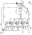
- FIG. 1 a heating system 2 is shown with a power source 4, a pump 6, a main line 8, four valves 10a, 10b, 10c and 10d in a heating circuit 9.
- the main line 8 is, as in FIG. 1 shown, no continuous line.
- the main line is often interrupted by components. These components are, for example, the power source 4, the pump 6, the consumers 10a, 10b, 10c and 10d and the flow collectors 12a, 12b, 12c and 12d.
- Each of these components is respectively connected to the main line 8 in such a way that in each case an interruption point of the main line is connected to a terminal of the component and that the respective other, associated interruption point is connected to another terminal of the component.
- the number of the reference character determines the essential meaning, whereas the subsequent letter assigns to the consumer 14a, then always followed by the letter a, to the consumer 14b, then always followed by the letter b, to the consumer 14c, then always followed by the letter c, to the consumer 14d , then always followed by the letter d. If several similar components addressed, so the letter is omitted.
- the valve 10a is a first component of the load module 52a.
- the consumer module 52a has the consumer supply line 16a, the consumer 14a, the consumer return line 18a and the flow collector 12a, and preferably a part of the main line 8 .
- a consumer module thus characterizes a group of components which are connected in series, in parallel or in another way, in particular several times in succession.
- the consumer module 52b (not labeled) comprises the valve 10b , the consumer feed line 16b, the consumer 14b, the consumer return line 18b and the flow collector 12b, and preferably a part of the main line 8 .
- Analogue consumer modules with the end letters c and d are also provided (and also not marked for reasons of clarity).
- the valves 10 are each connected by signal connections 38 to the controller 20 . Further, the controller is connected to the output sensor 26 through a signal connection 46 . The dispensing sensor measures the temperature of the fluid energy carrier in the main conduit between the solar collector 4 and the valve 10a. In addition, a light sensor 24 is connected by a signal connection 44 to the controller. Further, an environmental temperature sensor 22 is connected to the controller 20 through a signal connection. In addition, the feedback sensor 28 is connected to the regulator 20 through a signal connection 42 . Furthermore, the controller 20 has a memory that stores the respective recording power and consumer pre-set temperature for each consumer 14 .
- the controller 20 determines the current, in particular maximum, output power of the solar collector. This is, for example, 12,000 watts at a maximum discharge temperature of 40 ° C, 10,000 watts at a maximum discharge temperature of 45 ° C and 8,000 watts at a maximum discharge temperature of 60 ° C.
- the following data are further stored: For the consumer 14a is the recording power 500 watts and the consumer preset target temperature 30 ° C, for the consumer 14b , the power consumption is 10,000 watts and the consumer default temperature 40 ° C, for the consumer 14c is the Power consumption 1,000 watts and the consumer default temperature 30 ° C and for the consumer 14d the power consumption is 500 watts and the consumer default temperature is 25 ° C.
- the heating system 2 has a plurality of consumer dispensing sensors 30 for measuring the consumer output power and / or for measuring the consumer dispensing temperature.
- a consumer dispensing sensor 30 is mounted in or on that part of the main line 8 which directly follows a flow collector 12 assigned to the respective consumer.
- the consumer dispensing sensors 30 are each connected by a signal connection 32 to a multiplexer 50 .
- the multiplexer 50 is connected to the regulator 20 through a signal connection 34 .
- the controller 20 is connected by a signal connection 36 to the pump 6 .
- the controller 20 can set one of the valves 10 in such a way that the fluid flow from the main line 8 is directed to the connected feed line 16 .
- the valve 10 can also be provided in such a way that the fluid flow is directed to the main line 8 connected in the following.
- the controller can set the valve 10 in such a way that the incoming fluid flow through the main line 8 is divided into two partial streams. These partial flows can be directed into the corresponding supply line and into the further, corresponding main line.
- the flow collector 12 is basically the counterpart to the valve 10. Fluid streams from a respective main conduit and / or from a corresponding consumer return conduit 18 may be collected in the flow collector, mixed, and / or directed to a fluid flow to the continuing main conduit 8 .
- the regulator to set the valve 10a in such a way that the fluid flow through the valve from the main conduit 8a is directed (fully) to the continuing part of the main conduit 8.
- the flow collector 12a also allows the fluid flow to pass in an analogous manner, so that the fluid flow strikes the valve 12b without flowing through the consumer 14a . If the valve 12b is set by the regulator 20 in such a way that the fluid flow is directed exclusively to the consumer supply line 16b , the fluid flow consequently also completely flows through the consumer 14b and hits the flow collector 12b after flowing through the consumer return line 18a . Through the part of the main line 8a between the valve 10b and 12b then flows no volume flow into the flow collector 12b . From the flow collector 12b , the fluid energy carrier medium flows through another part of the main line 8 to the valve 10c. For the valves 10c and 10d analog positions of the valves are conceivable. The flow of the fluid energy carrier medium would then flow analogously.
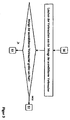
- FIGS. 2 to 6 a total of five parts of a related, preferred flowchart of a method for control are shown.
- the quantities referred to in the flowchart should refer to those already exemplified in the FIG. 1 have been introduced. Unless they have been introduced there, the sizes refer to the previous description.
- Four different elements were used to represent the flowchart.
- a conditional branch is represented by a rhombus.
- An operation is represented by a rectangle.
- An interface is represented by an oval and a data input or output is represented by a parallelogram.
- the interface elements each have the uppercase letter S followed by a number. Figure overlapping those interfaces with the same number, in particular star-shaped, be connected to each other. For example, the interface S1 is off FIG. 2 with the interface S1 off.
- the lines and arrows always indicate a connection and the direction to the next element. In this case, the arrow line leading away from the data input and output forms an exception.
- the data of the data output FIG. 2 namely, the measurement data of the sensors and the data of the memory (in particular of the controller), are preferably of the linked operations FIG. 5 and from the linked branch FIG. 6 readable.
- the controller selects that consumer whose input power is the smallest in terms of the output power of the power source
- the controller checks the condition of the subsequent branching: the condition is "input power less than or equal to the output power?"
- the controller thus checks whether the input power of the selected load is less than or equal to the output power of the power source the condition to ("yes") follows the controller of the connection vertically down to the next branch If the condition does not apply ("no"), the controller follows through the interface 6 to the topmost operation FIG. 3 , It is "Deleting the consumer from the quantity of selectable consumers”.
- the controller deletes the currently selected consumer from the set of selectable consumers. The amount of consumers is thus reduced by one, namely the previously selected, Consumer.
- the controller checks the following condition of the subsequent branch FIG. 3 , The condition is "Amount of selectable consumers greater than 0?". The controller therefore checks whether a consumer can still be selected. If at least one consumer can still be selected, the quantity is greater than 0. The answer to the branching condition would therefore be "yes”. Guided by the interface S3 to the FIG. 2 So the controller would again be the topmost operation out of the FIG. 2 namely, "selection of a selectable consumer whose intake has the smallest difference with respect to the output power". This has already been explained before. If the answer to the branching condition is from the FIG. 3 "No". The controller thus arrives at the branch via the interface S2 FIG. 6 , The branch off FIG.
- the controller 6 has the condition: "Significant and / or prolonged change of at least one value of the (measurement) data?".
- the controller thus continuously and / or at fixed intervals the measured data of the data input and / or data output FIG. 1 , namely: "Measurement data of the sensors and / or data of the memory.”
- the measurement data of the sensors are those data of the sensors which are used, for example, for the FIG. 1 have been introduced and / or have already been mentioned in the previous description. Also data of the memory, in particular that of the controller, were introduced. This data and the measured data are thus monitored by the controller.
- each size of the data may be given a lower threshold, an upper threshold, a lower gradient threshold and / or an upper gradient threshold. If the controller does not detect a significant and / or prolonged change in at least one value of the (measurement) data ("no"), the controller will repeat the test again. This loop of the schedule is also in FIG. 6 shown. Leading away from the right point of the rhombus, the arrow line again points to the upper peak of the rhombus, ie the entrance of the branch. For example, if the controller detects a significant and / or prolonged change in at least one value of the (measurement) data, such as light intensity, the response to the branching condition is "yes".
- the controller then performs the operation of FIG. 6 out.
- This is "reset the amount of selectable consumers to a fixed initial amount". So for the heating system there is a fixed initial amount of selectable consumers. These are preferably all consumers of the heating system. For FIG. 3 has already been introduced that this amount is gradually reduced. Since, after a significant and / or prolonged change in at least one value of the (measurement) data, the heating system may be in a significantly different state, it is necessary that all selectable consumers are initially available to the controller. Is the operation of FIG. 6 executed, the controller changes (through the interface 3) to the topmost operation FIG. 2 that was explained earlier. Also, the top branch was from the FIG. 2 already explained.
- the controller checks out the branching condition of the lower branch FIG. 2 , This is "flow temperature less than or equal to the discharge temperature?". The controller therefore checks whether the flow temperature of the selected consumer (selected by the uppermost operation FIG. 2 ) is less than or equal to the output temperature of the power source. If this condition is not fulfilled and the answer to the branching condition is "no", then the controller executes the uppermost operation from the FIG. 3 out. These and all other related elements have already been explained. If the branch condition of the lower branch is off FIG. 2 fulfilled and the answer is yes. so the controller performs the lowest operation of the FIG. 2 out.
- the controller can separately set the valves.
- the controller generates corresponding manipulated variable for this purpose.
- the regulator 20 sets the valve 10a in such a way that no flow through the consumer 14a is achieved. is guided and the valve 10b in such a way that at least a partial flow is passed through the consumer 14b. If the valve 10b is a switching valve, the full volume flow from the main line 8 will flow through the consumer 14b.
- Valves that are not explicitly set by the controller divert the complete volume flow to the corresponding consumer.
- the controller also checks the consumer output power of the pre-consumer. Then the controller compares this consumer output power with the respective recording powers of the selectable Nachvisorer. The controller then selects that Nachvisorer whose the difference between the respective consumption and the consumer. output power is the smallest. This selected consumer is then the after-consumer. The controller then checks the branch condition of the topmost branch FIG. 5 , It reads: "Recording power less than the consumer output power?". The controller thus checks whether the power consumption of the after-consumption device is less than the consumer output power of the pre-consumer.
- the controller executes the topmost operation from the FIG. 4 out.
- the corresponding subsequent elements as well as the operation FIG. 4 have already been explained.
- the controller checks the branch condition of the middle branch FIG. 5 , Is the flow temperature lower than or equal to the consumer discharge temperature? The controller thus checks whether the, in particular predeterminable, flow temperature of the after-consumer is less than or equal to the consumer output temperature of the pre-consumer. If the condition is not fulfilled and the answer is "no", then the controller executes the uppermost operation from the FIG. 4 out. These and all other related elements have already been explained. If the branch condition of the middle branch is off FIG.
- the controller checks the branching condition of the lower branch FIG. 5 , It reads "Sum of recording powers less than or equal to the output power?". The controller therefore checks whether the sum of the recording powers of the consumers flowing through, in particular including the recording power of the after-consumer, is less than or equal to the output power of the power source. If the branching condition is not fulfilled and the answer is "no", then the uppermost operation becomes out of FIG. 4 executed. If, on the other hand, the branching condition is fulfilled and the answer is yes, the lowest operation becomes the FIG. 5 executed. It is "placing the valve of the corresponding consumer, so that at least a partial flow is directed to this". The controller thus provides the valve of the selected after-consumer, so that at least a partial flow of the pre-consumer is directed to the Nachvisorer. The controller then executes the topmost operation from the FIG. 4 out.
- the flowchart has no start or end point.
- the sequence of the flowchart can therefore be executed "endlessly" by the controller.
Landscapes
- Engineering & Computer Science (AREA)
- Physics & Mathematics (AREA)
- Thermal Sciences (AREA)
- Chemical & Material Sciences (AREA)
- Combustion & Propulsion (AREA)
- Mechanical Engineering (AREA)
- General Engineering & Computer Science (AREA)
- Life Sciences & Earth Sciences (AREA)
- Sustainable Development (AREA)
- Sustainable Energy (AREA)
- Management, Administration, Business Operations System, And Electronic Commerce (AREA)
- Supply And Distribution Of Alternating Current (AREA)
Claims (8)
- Procédé de réglage, qui est réalisé dans une installation qui présente un capteur solaire en tant que source de puissance, une pompe, une conduite principale et au moins une vanne dans un circuit de chauffage ainsi que plusieurs consommateurs,i. la conduite principale étant parcourue au moins partiellement par un milieu vecteur d'énergie fluide,ii. la source de puissance étant aménagée pour transmettre au milieu vecteur d'énergie une puissance produite momentanée définie, en particulier la puissance produite maximale disponible,iii. les consommateurs présentant respectivement un besoin de puissance absorbée momentané, caractérisé en cequ'un régulateur (20), qui règle la vanne (10) au moins au nombre de un de telle sorte qu'au moins un flux partiel du milieu vecteur d'énergie fluide est détourné vers le consommateur, appelé ici premier consommateur, parmi les plusieurs consommateurs (14) desquels la puissance absorbée est inférieure à la puissance produite, duquel la puissance absorbée présente la plus petit différence en valeur par rapport à la puissance produite.
- Procédé selon la revendication précédente, caractérisé en ce que la source de puissance (4) est un capteur à tubes sous vide et/ou un capteur plat ou un capteur cylindro-parabolique.
- Procédé selon l'une des revendications précédentes, caractérisé en ce que plusieurs ou tous les consommateurs (14) présentent respectivement une conduite aller de consommateur (16) et une conduite retour de consommateur (18) et/ou en ce que le milieu vecteur d'énergie quitte la source de puissance avec une température produite, et/ou le régulateur (20) règle, par un réglage de la pompe (6), la température produite à une température de consigne aller de consommateur pouvant être prédéfinie, en particulier la température aller du premier consommateur.
- Procédé selon l'une des revendications précédentes, caractérisé en ce que le régulateur (20) règle la température produite à une température de consigne aller de consommateur qui est inférieure à une température produite maximale ou est égale à la température produite maximale.
- Procédé selon l'une des revendications précédentes, caractérisé en ce que la puissance produite, en particulier maximale, est déterminée à partir d'un champ caractéristique de puissance et/ou en ce que la température produite maximale est déterminée à partir d'un champ caractéristique de température qui dressent respectivement le tableau de températures produites, de températures retour de capteur, de flux volumiques de capteur, d'intensités lumineuses, de températures ambiantes, de surfaces de capteur, d'angles de capteur, d'angles azimutaux de capteur et/ou de rendements de capteur les uns par rapport aux autres.
- Procédé selon l'une des revendications précédentes, caractérisé en ce que la détermination de la puissance produite, en particulier maximale, et/ou de la température produite maximale comprend les étapes suivantes :mesure de la température produite, de la température retour de capteur, du flux volumique de capteur, de l'intensité lumineuse, de la température ambiante, de la surface de capteur, de l'angle de capteur, de l'angle azimutal de capteur et/ou du rendement de capteur ; ensuitedétermination de la puissance produite, en particulier maximale, la température produite, la température retour de capteur, le flux volumique de capteur,l'intensité lumineuse, la température ambiante, la surface de capteur, l'angle de capteur, l'angle azimutal de capteur et/ou le rendement de capteur étant stipulés respectivement par leur valeur mesurée et/ou pouvant être prédéfinie, en particulier de l'extérieur.
- Procédé selon l'une des revendications précédentes, caractérisé en ce que le milieu vecteur d'énergie quitte un consommateur, appelé ici pré-consommateur, parmi les consommateurs (14) et/ou un collecteur d'écoulement (12) affecté au pré-consommateur avec une puissance produite de consommateur et/ou avec une température produite de consommateur, et/ou le régulateur (20) règle une vanne (10) du consommateur (10), appelé ici post-consommateur, parmi les consommateurs suivants dont la puissance absorbée présente en valeur, par rapport à la puissance produite de consommateur du pré-consommateur, la plus petite différence de telle sorte qu'au moins un flux partiel du flux du milieu vecteur d'énergie fluide du pré-consommateur est dévié, en particulier directement, vers le post-consommateur.
- Procédé selon la revendication précédente, caractérisé en ce que la puissance absorbée d'un post-consommateur est inférieure ou égale à la puissance produite de consommateur d'un pré-consommateur direct et/ou en ce que la température aller, en particulier pouvant être prédéfinie, d'un post-consommateur est inférieure ou égale à la température produite de consommateur d'un préconsommateur direct.
Priority Applications (2)
| Application Number | Priority Date | Filing Date | Title |
|---|---|---|---|
| EP10013541.7A EP2442037B1 (fr) | 2010-10-12 | 2010-10-12 | Procédé de réglage d'une installation de chauffage |
| ES10013541.7T ES2588402T3 (es) | 2010-10-12 | 2010-10-12 | Procedimiento para la regulación de una instalación de calefacción |
Applications Claiming Priority (1)
| Application Number | Priority Date | Filing Date | Title |
|---|---|---|---|
| EP10013541.7A EP2442037B1 (fr) | 2010-10-12 | 2010-10-12 | Procédé de réglage d'une installation de chauffage |
Publications (2)
| Publication Number | Publication Date |
|---|---|
| EP2442037A1 EP2442037A1 (fr) | 2012-04-18 |
| EP2442037B1 true EP2442037B1 (fr) | 2016-06-01 |
Family
ID=43533357
Family Applications (1)
| Application Number | Title | Priority Date | Filing Date |
|---|---|---|---|
| EP10013541.7A Active EP2442037B1 (fr) | 2010-10-12 | 2010-10-12 | Procédé de réglage d'une installation de chauffage |
Country Status (2)
| Country | Link |
|---|---|
| EP (1) | EP2442037B1 (fr) |
| ES (1) | ES2588402T3 (fr) |
Families Citing this family (2)
| Publication number | Priority date | Publication date | Assignee | Title |
|---|---|---|---|---|
| CN103256649B (zh) * | 2013-05-20 | 2016-03-16 | 张铸志 | 太阳能光热光电联合采暖系统 |
| US10006642B2 (en) | 2014-05-09 | 2018-06-26 | Jerritt L. Gluck | Systems and methods for controlling conditioned fluid systems in a built environment |
Family Cites Families (5)
| Publication number | Priority date | Publication date | Assignee | Title |
|---|---|---|---|---|
| DE4124304C2 (de) | 1991-07-23 | 1994-11-24 | Heimeier Gmbh Metall Theodor | Thermostatisch betätigbares Dreiwege-Heizkörperventil für Einrohrheizungsanlagen |
| DE19710645A1 (de) * | 1997-03-14 | 1998-09-24 | Bosch Gmbh Robert | Anordnung und Verfahren zur Anpassung der Leistung eines Heizgerätes |
| AT504773B1 (de) * | 2007-01-30 | 2009-02-15 | Logotherm Regelsysteme Gmbh | Solarregelung |
| KR100924466B1 (ko) * | 2007-12-07 | 2009-11-03 | 주식회사 경동네트웍 | 난방환경에 적응하는 각방 실내온도 제어방법 |
| US20100045470A1 (en) * | 2008-07-31 | 2010-02-25 | Araiza Steven P | Steam distribution control system and method for a steam heating system |
-
2010
- 2010-10-12 EP EP10013541.7A patent/EP2442037B1/fr active Active
- 2010-10-12 ES ES10013541.7T patent/ES2588402T3/es active Active
Also Published As
| Publication number | Publication date |
|---|---|
| EP2442037A1 (fr) | 2012-04-18 |
| ES2588402T3 (es) | 2016-11-02 |
Similar Documents
| Publication | Publication Date | Title |
|---|---|---|
| EP2870414B1 (fr) | Procédé pour le fonctionnement d'un échangeur thermique ainsi qu'installation hvac pour la réalisation du procédé | |
| EP2871423B1 (fr) | Procédé de régulation pour un système de chauffage et/ou de refroidissement comprenant au moins un circuit de charge et dispositif de distribution pour un système de chauffage et/ou de refroidissement | |
| DE102008057730A1 (de) | Verfahren zum Betreiben eines Systems zum Transport thermischer Energie über ein flüssiges Medium | |
| EP3270066B1 (fr) | Système d'approvisionnement en énergie pourvu d'un accumulateur de chaleur latente et procédé de fonctionnement d'un système d'approvisionnement en énergie | |
| EP0035085A1 (fr) | Installation pour le transport de chaleur au moyen d'un fluide | |
| DE102015014378A1 (de) | Verfahren zur Regelung einer Kreiselpumpe sowie zugehöriges Pumpensystem | |
| EP2375175A2 (fr) | Dispositif destiné à l'alimentation en chaleur de bâtiments | |
| DE2947618C2 (de) | Regelverfahren für einen mehrstufigen Zentrifugalverdichter | |
| DE102014016791B4 (de) | Verfahren zur hydraulischen Regelung mehrerer Heizkreisläufe am Verteilerbalken | |
| AT521703B1 (de) | Warmwasserbereitungsanlage | |
| DE10218776B3 (de) | Anlage zur Versorgung von Verbrauchern mit Wärmeenergie unterschiedlicher Energieniveaus | |
| EP2442037B1 (fr) | Procédé de réglage d'une installation de chauffage | |
| DE3203832A1 (de) | Verfahren und regelvorrichtung zum regeln eines heizungskreises | |
| EP3431889A1 (fr) | Circuit d'alimentation pour un agent caloporteur pour un consommateur, installation industrielle et procédé de fonctionnement un tel circuit d'alimentation | |
| EP2287547A1 (fr) | Pompe à chaleur et procédé de réglage de la température d'entrée de sources sur une pompe à chaleur | |
| EP0872788B1 (fr) | Régulation pour un système de chauffage ou de réfrigération avec une mémoire de compensation | |
| DE1751724A1 (de) | Mischkondensatorenanlage fuer Dampfturbinenkraftwerke | |
| EP3076110A1 (fr) | Systeme fluidique et procede de commande d'un systeme fluidique | |
| DE10130805C1 (de) | Anordnung zur Warmwasserbereitung von Brauchwasser | |
| DE102014000671B4 (de) | Solaranlage und Verfahren zum Betreiben einer solchen | |
| EP2226500B1 (fr) | Régulateur de parc éolien | |
| DE10244256A1 (de) | Heizanlage und/oder Kühlanlage mit mindestens einer Wärmequelle | |
| CH663268A5 (de) | Heizanlage an einem fernheizsystem. | |
| EP2442052A1 (fr) | Procédé de réglage développé dans une installation de chauffage | |
| DE2116525A1 (de) | Warmwasser-sammelheizungsanlage |
Legal Events
| Date | Code | Title | Description |
|---|---|---|---|
| PUAI | Public reference made under article 153(3) epc to a published international application that has entered the european phase |
Free format text: ORIGINAL CODE: 0009012 |
|
| AK | Designated contracting states |
Kind code of ref document: A1 Designated state(s): AL AT BE BG CH CY CZ DE DK EE ES FI FR GB GR HR HU IE IS IT LI LT LU LV MC MK MT NL NO PL PT RO RS SE SI SK SM TR |
|
| AX | Request for extension of the european patent |
Extension state: BA ME |
|
| 17P | Request for examination filed |
Effective date: 20130124 |
|
| RAP1 | Party data changed (applicant data changed or rights of an application transferred) |
Owner name: ACTIVE BUILDING TECHNOLOGIES INTELLIGENT SYSTEMS, |
|
| GRAP | Despatch of communication of intention to grant a patent |
Free format text: ORIGINAL CODE: EPIDOSNIGR1 |
|
| RIC1 | Information provided on ipc code assigned before grant |
Ipc: F24D 19/00 20060101ALI20150714BHEP Ipc: F24D 19/10 20060101AFI20150714BHEP |
|
| INTG | Intention to grant announced |
Effective date: 20150820 |
|
| INTG | Intention to grant announced |
Effective date: 20151218 |
|
| GRAS | Grant fee paid |
Free format text: ORIGINAL CODE: EPIDOSNIGR3 |
|
| GRAA | (expected) grant |
Free format text: ORIGINAL CODE: 0009210 |
|
| AK | Designated contracting states |
Kind code of ref document: B1 Designated state(s): AL AT BE BG CH CY CZ DE DK EE ES FI FR GB GR HR HU IE IS IT LI LT LU LV MC MK MT NL NO PL PT RO RS SE SI SK SM TR |
|
| REG | Reference to a national code |
Ref country code: GB Ref legal event code: FG4D Free format text: NOT ENGLISH |
|
| REG | Reference to a national code |
Ref country code: CH Ref legal event code: EP Ref country code: AT Ref legal event code: REF Ref document number: 804122 Country of ref document: AT Kind code of ref document: T Effective date: 20160615 |
|
| REG | Reference to a national code |
Ref country code: IE Ref legal event code: FG4D Free format text: LANGUAGE OF EP DOCUMENT: GERMAN |
|
| REG | Reference to a national code |
Ref country code: DE Ref legal event code: R096 Ref document number: 502010011764 Country of ref document: DE |
|
| REG | Reference to a national code |
Ref country code: LT Ref legal event code: MG4D |
|
| REG | Reference to a national code |
Ref country code: NL Ref legal event code: MP Effective date: 20160601 |
|
| REG | Reference to a national code |
Ref country code: FR Ref legal event code: PLFP Year of fee payment: 7 |
|
| PG25 | Lapsed in a contracting state [announced via postgrant information from national office to epo] |
Ref country code: FI Free format text: LAPSE BECAUSE OF FAILURE TO SUBMIT A TRANSLATION OF THE DESCRIPTION OR TO PAY THE FEE WITHIN THE PRESCRIBED TIME-LIMIT Effective date: 20160601 Ref country code: NO Free format text: LAPSE BECAUSE OF FAILURE TO SUBMIT A TRANSLATION OF THE DESCRIPTION OR TO PAY THE FEE WITHIN THE PRESCRIBED TIME-LIMIT Effective date: 20160901 Ref country code: LT Free format text: LAPSE BECAUSE OF FAILURE TO SUBMIT A TRANSLATION OF THE DESCRIPTION OR TO PAY THE FEE WITHIN THE PRESCRIBED TIME-LIMIT Effective date: 20160601 |
|
| REG | Reference to a national code |
Ref country code: ES Ref legal event code: FG2A Ref document number: 2588402 Country of ref document: ES Kind code of ref document: T3 Effective date: 20161102 |
|
| PG25 | Lapsed in a contracting state [announced via postgrant information from national office to epo] |
Ref country code: LV Free format text: LAPSE BECAUSE OF FAILURE TO SUBMIT A TRANSLATION OF THE DESCRIPTION OR TO PAY THE FEE WITHIN THE PRESCRIBED TIME-LIMIT Effective date: 20160601 Ref country code: HR Free format text: LAPSE BECAUSE OF FAILURE TO SUBMIT A TRANSLATION OF THE DESCRIPTION OR TO PAY THE FEE WITHIN THE PRESCRIBED TIME-LIMIT Effective date: 20160601 Ref country code: NL Free format text: LAPSE BECAUSE OF FAILURE TO SUBMIT A TRANSLATION OF THE DESCRIPTION OR TO PAY THE FEE WITHIN THE PRESCRIBED TIME-LIMIT Effective date: 20160601 Ref country code: SE Free format text: LAPSE BECAUSE OF FAILURE TO SUBMIT A TRANSLATION OF THE DESCRIPTION OR TO PAY THE FEE WITHIN THE PRESCRIBED TIME-LIMIT Effective date: 20160601 Ref country code: RS Free format text: LAPSE BECAUSE OF FAILURE TO SUBMIT A TRANSLATION OF THE DESCRIPTION OR TO PAY THE FEE WITHIN THE PRESCRIBED TIME-LIMIT Effective date: 20160601 |
|
| PG25 | Lapsed in a contracting state [announced via postgrant information from national office to epo] |
Ref country code: SK Free format text: LAPSE BECAUSE OF FAILURE TO SUBMIT A TRANSLATION OF THE DESCRIPTION OR TO PAY THE FEE WITHIN THE PRESCRIBED TIME-LIMIT Effective date: 20160601 Ref country code: RO Free format text: LAPSE BECAUSE OF FAILURE TO SUBMIT A TRANSLATION OF THE DESCRIPTION OR TO PAY THE FEE WITHIN THE PRESCRIBED TIME-LIMIT Effective date: 20160601 Ref country code: IT Free format text: LAPSE BECAUSE OF FAILURE TO SUBMIT A TRANSLATION OF THE DESCRIPTION OR TO PAY THE FEE WITHIN THE PRESCRIBED TIME-LIMIT Effective date: 20160601 Ref country code: EE Free format text: LAPSE BECAUSE OF FAILURE TO SUBMIT A TRANSLATION OF THE DESCRIPTION OR TO PAY THE FEE WITHIN THE PRESCRIBED TIME-LIMIT Effective date: 20160601 Ref country code: CZ Free format text: LAPSE BECAUSE OF FAILURE TO SUBMIT A TRANSLATION OF THE DESCRIPTION OR TO PAY THE FEE WITHIN THE PRESCRIBED TIME-LIMIT Effective date: 20160601 Ref country code: IS Free format text: LAPSE BECAUSE OF FAILURE TO SUBMIT A TRANSLATION OF THE DESCRIPTION OR TO PAY THE FEE WITHIN THE PRESCRIBED TIME-LIMIT Effective date: 20161001 |
|
| REG | Reference to a national code |
Ref country code: DE Ref legal event code: R082 Ref document number: 502010011764 Country of ref document: DE Representative=s name: HOFFMANN - EITLE PATENT- UND RECHTSANWAELTE PA, DE Ref country code: DE Ref legal event code: R082 Ref document number: 502010011764 Country of ref document: DE Representative=s name: SASSE, STEFAN, PROF. DR.-ING., DE |
|
| PG25 | Lapsed in a contracting state [announced via postgrant information from national office to epo] |
Ref country code: PT Free format text: LAPSE BECAUSE OF FAILURE TO SUBMIT A TRANSLATION OF THE DESCRIPTION OR TO PAY THE FEE WITHIN THE PRESCRIBED TIME-LIMIT Effective date: 20161003 Ref country code: SM Free format text: LAPSE BECAUSE OF FAILURE TO SUBMIT A TRANSLATION OF THE DESCRIPTION OR TO PAY THE FEE WITHIN THE PRESCRIBED TIME-LIMIT Effective date: 20160601 Ref country code: BE Free format text: LAPSE BECAUSE OF NON-PAYMENT OF DUE FEES Effective date: 20161031 Ref country code: PL Free format text: LAPSE BECAUSE OF FAILURE TO SUBMIT A TRANSLATION OF THE DESCRIPTION OR TO PAY THE FEE WITHIN THE PRESCRIBED TIME-LIMIT Effective date: 20160601 |
|
| REG | Reference to a national code |
Ref country code: DE Ref legal event code: R097 Ref document number: 502010011764 Country of ref document: DE |
|
| PLBE | No opposition filed within time limit |
Free format text: ORIGINAL CODE: 0009261 |
|
| STAA | Information on the status of an ep patent application or granted ep patent |
Free format text: STATUS: NO OPPOSITION FILED WITHIN TIME LIMIT |
|
| 26N | No opposition filed |
Effective date: 20170302 |
|
| PG25 | Lapsed in a contracting state [announced via postgrant information from national office to epo] |
Ref country code: SI Free format text: LAPSE BECAUSE OF FAILURE TO SUBMIT A TRANSLATION OF THE DESCRIPTION OR TO PAY THE FEE WITHIN THE PRESCRIBED TIME-LIMIT Effective date: 20160601 Ref country code: DK Free format text: LAPSE BECAUSE OF FAILURE TO SUBMIT A TRANSLATION OF THE DESCRIPTION OR TO PAY THE FEE WITHIN THE PRESCRIBED TIME-LIMIT Effective date: 20160601 |
|
| REG | Reference to a national code |
Ref country code: CH Ref legal event code: PL |
|
| GBPC | Gb: european patent ceased through non-payment of renewal fee |
Effective date: 20161012 |
|
| REG | Reference to a national code |
Ref country code: IE Ref legal event code: MM4A |
|
| PG25 | Lapsed in a contracting state [announced via postgrant information from national office to epo] |
Ref country code: CH Free format text: LAPSE BECAUSE OF NON-PAYMENT OF DUE FEES Effective date: 20161031 Ref country code: LI Free format text: LAPSE BECAUSE OF NON-PAYMENT OF DUE FEES Effective date: 20161031 Ref country code: GB Free format text: LAPSE BECAUSE OF NON-PAYMENT OF DUE FEES Effective date: 20161012 |
|
| PG25 | Lapsed in a contracting state [announced via postgrant information from national office to epo] |
Ref country code: LU Free format text: LAPSE BECAUSE OF NON-PAYMENT OF DUE FEES Effective date: 20161012 |
|
| REG | Reference to a national code |
Ref country code: FR Ref legal event code: PLFP Year of fee payment: 8 |
|
| PG25 | Lapsed in a contracting state [announced via postgrant information from national office to epo] |
Ref country code: IE Free format text: LAPSE BECAUSE OF NON-PAYMENT OF DUE FEES Effective date: 20161012 |
|
| REG | Reference to a national code |
Ref country code: BE Ref legal event code: MM Effective date: 20161031 |
|
| PG25 | Lapsed in a contracting state [announced via postgrant information from national office to epo] |
Ref country code: CY Free format text: LAPSE BECAUSE OF FAILURE TO SUBMIT A TRANSLATION OF THE DESCRIPTION OR TO PAY THE FEE WITHIN THE PRESCRIBED TIME-LIMIT Effective date: 20160601 Ref country code: HU Free format text: LAPSE BECAUSE OF FAILURE TO SUBMIT A TRANSLATION OF THE DESCRIPTION OR TO PAY THE FEE WITHIN THE PRESCRIBED TIME-LIMIT; INVALID AB INITIO Effective date: 20101012 |
|
| PG25 | Lapsed in a contracting state [announced via postgrant information from national office to epo] |
Ref country code: GR Free format text: LAPSE BECAUSE OF FAILURE TO SUBMIT A TRANSLATION OF THE DESCRIPTION OR TO PAY THE FEE WITHIN THE PRESCRIBED TIME-LIMIT Effective date: 20160601 Ref country code: MT Free format text: LAPSE BECAUSE OF FAILURE TO SUBMIT A TRANSLATION OF THE DESCRIPTION OR TO PAY THE FEE WITHIN THE PRESCRIBED TIME-LIMIT Effective date: 20160601 Ref country code: MC Free format text: LAPSE BECAUSE OF FAILURE TO SUBMIT A TRANSLATION OF THE DESCRIPTION OR TO PAY THE FEE WITHIN THE PRESCRIBED TIME-LIMIT Effective date: 20160601 Ref country code: MK Free format text: LAPSE BECAUSE OF FAILURE TO SUBMIT A TRANSLATION OF THE DESCRIPTION OR TO PAY THE FEE WITHIN THE PRESCRIBED TIME-LIMIT Effective date: 20160601 Ref country code: TR Free format text: LAPSE BECAUSE OF FAILURE TO SUBMIT A TRANSLATION OF THE DESCRIPTION OR TO PAY THE FEE WITHIN THE PRESCRIBED TIME-LIMIT Effective date: 20160601 |
|
| PG25 | Lapsed in a contracting state [announced via postgrant information from national office to epo] |
Ref country code: BG Free format text: LAPSE BECAUSE OF FAILURE TO SUBMIT A TRANSLATION OF THE DESCRIPTION OR TO PAY THE FEE WITHIN THE PRESCRIBED TIME-LIMIT Effective date: 20160601 |
|
| REG | Reference to a national code |
Ref country code: FR Ref legal event code: PLFP Year of fee payment: 9 |
|
| PG25 | Lapsed in a contracting state [announced via postgrant information from national office to epo] |
Ref country code: AL Free format text: LAPSE BECAUSE OF FAILURE TO SUBMIT A TRANSLATION OF THE DESCRIPTION OR TO PAY THE FEE WITHIN THE PRESCRIBED TIME-LIMIT Effective date: 20160601 |
|
| REG | Reference to a national code |
Ref country code: DE Ref legal event code: R082 Ref document number: 502010011764 Country of ref document: DE Representative=s name: SASSE, STEFAN, PROF. DR.-ING., DE Ref country code: DE Ref legal event code: R082 Ref document number: 502010011764 Country of ref document: DE |
|
| REG | Reference to a national code |
Ref country code: DE Ref legal event code: R082 Ref document number: 502010011764 Country of ref document: DE Representative=s name: SASSE, STEFAN, PROF. DR.-ING., DE |
|
| PGFP | Annual fee paid to national office [announced via postgrant information from national office to epo] |
Ref country code: DE Payment date: 20251010 Year of fee payment: 16 |
|
| PGFP | Annual fee paid to national office [announced via postgrant information from national office to epo] |
Ref country code: AT Payment date: 20251013 Year of fee payment: 16 |
|
| PGFP | Annual fee paid to national office [announced via postgrant information from national office to epo] |
Ref country code: FR Payment date: 20251014 Year of fee payment: 16 |
|
| PGFP | Annual fee paid to national office [announced via postgrant information from national office to epo] |
Ref country code: ES Payment date: 20251112 Year of fee payment: 16 |