EP2870414B1 - Procédé pour le fonctionnement d'un échangeur thermique ainsi qu'installation hvac pour la réalisation du procédé - Google Patents
Procédé pour le fonctionnement d'un échangeur thermique ainsi qu'installation hvac pour la réalisation du procédé Download PDFInfo
- Publication number
- EP2870414B1 EP2870414B1 EP13733229.2A EP13733229A EP2870414B1 EP 2870414 B1 EP2870414 B1 EP 2870414B1 EP 13733229 A EP13733229 A EP 13733229A EP 2870414 B1 EP2870414 B1 EP 2870414B1
- Authority
- EP
- European Patent Office
- Prior art keywords
- heat exchanger
- temperature
- max
- heat
- flow
- Prior art date
- Legal status (The legal status is an assumption and is not a legal conclusion. Google has not performed a legal analysis and makes no representation as to the accuracy of the status listed.)
- Active
Links
Images


Classifications
-
- F—MECHANICAL ENGINEERING; LIGHTING; HEATING; WEAPONS; BLASTING
- F24—HEATING; RANGES; VENTILATING
- F24F—AIR-CONDITIONING; AIR-HUMIDIFICATION; VENTILATION; USE OF AIR CURRENTS FOR SCREENING
- F24F11/00—Control or safety arrangements
-
- F—MECHANICAL ENGINEERING; LIGHTING; HEATING; WEAPONS; BLASTING
- F24—HEATING; RANGES; VENTILATING
- F24F—AIR-CONDITIONING; AIR-HUMIDIFICATION; VENTILATION; USE OF AIR CURRENTS FOR SCREENING
- F24F11/00—Control or safety arrangements
- F24F11/70—Control systems characterised by their outputs; Constructional details thereof
- F24F11/80—Control systems characterised by their outputs; Constructional details thereof for controlling the temperature of the supplied air
- F24F11/83—Control systems characterised by their outputs; Constructional details thereof for controlling the temperature of the supplied air by controlling the supply of heat-exchange fluids to heat-exchangers
-
- F—MECHANICAL ENGINEERING; LIGHTING; HEATING; WEAPONS; BLASTING
- F24—HEATING; RANGES; VENTILATING
- F24F—AIR-CONDITIONING; AIR-HUMIDIFICATION; VENTILATION; USE OF AIR CURRENTS FOR SCREENING
- F24F11/00—Control or safety arrangements
- F24F11/30—Control or safety arrangements for purposes related to the operation of the system, e.g. for safety or monitoring
- F24F11/46—Improving electric energy efficiency or saving
-
- F—MECHANICAL ENGINEERING; LIGHTING; HEATING; WEAPONS; BLASTING
- F24—HEATING; RANGES; VENTILATING
- F24F—AIR-CONDITIONING; AIR-HUMIDIFICATION; VENTILATION; USE OF AIR CURRENTS FOR SCREENING
- F24F11/00—Control or safety arrangements
- F24F11/70—Control systems characterised by their outputs; Constructional details thereof
- F24F11/80—Control systems characterised by their outputs; Constructional details thereof for controlling the temperature of the supplied air
- F24F11/83—Control systems characterised by their outputs; Constructional details thereof for controlling the temperature of the supplied air by controlling the supply of heat-exchange fluids to heat-exchangers
- F24F11/84—Control systems characterised by their outputs; Constructional details thereof for controlling the temperature of the supplied air by controlling the supply of heat-exchange fluids to heat-exchangers using valves
-
- G—PHYSICS
- G05—CONTROLLING; REGULATING
- G05D—SYSTEMS FOR CONTROLLING OR REGULATING NON-ELECTRIC VARIABLES
- G05D23/00—Control of temperature
- G05D23/19—Control of temperature characterised by the use of electric means
-
- F—MECHANICAL ENGINEERING; LIGHTING; HEATING; WEAPONS; BLASTING
- F24—HEATING; RANGES; VENTILATING
- F24F—AIR-CONDITIONING; AIR-HUMIDIFICATION; VENTILATION; USE OF AIR CURRENTS FOR SCREENING
- F24F11/00—Control or safety arrangements
- F24F11/30—Control or safety arrangements for purposes related to the operation of the system, e.g. for safety or monitoring
-
- F—MECHANICAL ENGINEERING; LIGHTING; HEATING; WEAPONS; BLASTING
- F24—HEATING; RANGES; VENTILATING
- F24F—AIR-CONDITIONING; AIR-HUMIDIFICATION; VENTILATION; USE OF AIR CURRENTS FOR SCREENING
- F24F2110/00—Control inputs relating to air properties
- F24F2110/10—Temperature
-
- F—MECHANICAL ENGINEERING; LIGHTING; HEATING; WEAPONS; BLASTING
- F24—HEATING; RANGES; VENTILATING
- F24F—AIR-CONDITIONING; AIR-HUMIDIFICATION; VENTILATION; USE OF AIR CURRENTS FOR SCREENING
- F24F2140/00—Control inputs relating to system states
- F24F2140/20—Heat-exchange fluid temperature
-
- F—MECHANICAL ENGINEERING; LIGHTING; HEATING; WEAPONS; BLASTING
- F28—HEAT EXCHANGE IN GENERAL
- F28F—DETAILS OF HEAT-EXCHANGE AND HEAT-TRANSFER APPARATUS, OF GENERAL APPLICATION
- F28F27/00—Control arrangements or safety devices specially adapted for heat-exchange or heat-transfer apparatus
Definitions
- the present invention relates to the field of air conditioning technology. It relates to a method for operating a heat exchanger according to the preamble of claim 1. It also relates to an HVAC system for performing the method.
- HVAC Heating, cooling, air conditioning and ventilation of rooms in buildings.
- HVAC stands eating H, V entilation and A ir C onditioning.
- heat and / or cold is generated centrally and led to the appropriate rooms via a suitable heat transfer medium, usually water, where the heat or cold is given off, for example, to the room air there via local heat exchangers.
- the heat flow required to reach a predetermined room temperature and delivered or received via the local heat exchanger is often regulated by changing the primary-side mass flow of the heat transfer medium accordingly.
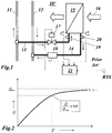
- a section from an exemplary HVAC system is in Fig. 1 shown.
- the HVAC system 10 'of Fig. 1 comprises a local heat exchanger 15 which is connected on the primary side via a flow branch line 13 to a higher-level flow line 11 and via a return branch line 14 to a higher-level return line 12.
- Flow line 11 and return line 12 are with a not shown central facility for heat and / or cold generation connected.
- an air flow 16 flows through the heat exchanger 15, which absorbs heat in the heating case and emits heat to the cooling case.
- To set the mass flow of the heat transfer medium through the primary side of the heat exchanger 15 is in the example Fig. 1 In the flow branch line 13, a control valve 17 is arranged that is controlled by a controller 21.
- the mass flow is determined via the corresponding volume flow V ⁇ , which is measured with a flow meter 18 used, for example, in the return branch line 14.
- the measurement of the two temperatures T a W and T out W takes place by means of two temperature sensors 19 and 20, which are expediently arranged at the primary-side inlet or outlet of the heat exchanger 15.
- a comparable arrangement is, for example, from the publication EP 0 035 085 A1 known where it is used in connection with a consumption measurement.
- a temperature sensor is provided in the room to be heated / air-conditioned, which controls the supply of the heat transfer medium on the primary side of the heat exchanger.
- the room temperature sensor (RTS in Fig. 1 ) an increased heat requirement, the valve on the primary side of the heat exchanger is opened further (with the flow temperature remaining the same) in order to provide more heat.
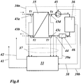
- the heat flow Q transmitted via the heat exchanger shows a course that in Fig. 2 is reproduced.
- the course of the curve depends - as will be explained further below - on the one hand on the design of the heat exchanger (in particular on the heat transfer surface A, the heat transfer coefficient k, a factor F and an exponent n) and on the other hand on the temperature, the mass flow and the heat capacity of the Medium on the secondary side of the heat exchanger.
- the curve which initially rises sharply in the case of small volume flows, flattens out more and more with increasing volume flow and asymptotically approaches a limit value Q S max (saturation).
- Q S max saturation
- the flattening of the curve means that, for the same increases in heat flow, ever greater increases in volume flow and thus more and more pump power must be made available.
- the power to be used for the pump increases with the third power of the volume flow, while the heat transferred increases only slightly. However, this makes little sense from an economic point of view.
- a predetermined value is in the ratio Q ⁇ Q ⁇ Max , the degree of saturation of the heat exchanger.
- a predetermined value can be chosen, for example, at 0.8, as shown in Fig. 2 is entered.
- the pump power to be applied by the system can be limited without having to accept large losses in the amount of heat transferred, which leads to advantages in the design and operation of the system.
- the current heat flow in the heat exchanger and thus the point on the in Fig. 2 shown curve can be determined by measuring the volume flow and the primary temperatures.
- the curve and its asymptote can only be determined by the controller 21 for certain conditions on the secondary side of the heat exchanger by measurements over a longer period of time.
- this requires a flow meter that is comparatively complex and - if it contains moving parts - can also be susceptible to faults.
- the publication US 2009/090498 A1 on the other hand describes a temperature control device which controls the temperature of a first medium by heat exchange between the first medium and a second medium via a heat exchanger, an exposure device for components with this temperature control device and a method for producing components using the exposure device.
- a correction processing unit which, based on temperatures detected by a first temperature sensor, a second temperature sensor, a third temperature sensor and a fourth temperature sensor, calculates a heat exchange quantity of the heat exchanger, calculates a logarithmic mean temperature difference or an average temperature in the heat exchanger, and the flow rate of the second medium is determined to calculate a total heat transfer coefficient of the heat exchanger based on the heat exchange amount logarithmic mean temperature difference or the average temperature and the flow rate of the second medium to determine, and to correct a gain of the control operating unit based on a change in the heat exchange amount with a change in the flow rate of the second medium fed into the heat exchanger.
- the invention is based on a method for operating a heat exchanger, through which a heat transfer medium flows through the heat exchanger on a primary side, which enters the heat exchanger at a first temperature and exits the heat exchanger at a second temperature, and a heat flow on a secondary side in the case of heating emits to a secondary medium flowing through the heat exchanger or, in the case of cooling, absorbs a heat flow from the secondary medium, which enters the heat exchanger at a third temperature and exits the heat exchanger again at a fourth temperature, the heat exchanger being able to transmit a maximum heat flow.
- It is characterized in that at least three of the four temperatures are measured, and from these measured temperatures the respective degree of saturation of the heat exchanger is determined and used to control the operation of the heat exchanger, and that the heat exchanger is part of an HVAC system.
- An embodiment of the method according to the invention is characterized in that the flow of the heat transfer medium on the primary side of the heat exchanger can be controlled and that the flow of the heat transfer medium on the primary side of the heat exchanger is limited when the degree of saturation of the heat exchanger reaches a predetermined value.
- Another embodiment of the method according to the invention is characterized in that the flow of the secondary medium on the secondary side of the heat exchanger can be controlled and that the degree of saturation of the heat exchanger is used to control the flow of the secondary medium.
- the heat transfer medium can be water.
- the secondary medium can be air.
- Q ⁇ Q ⁇ Max f T a W T out W T a L used.
- the heat exchanger can be operated in the context of the invention in cocurrent, crossflow or countercurrent or mixed forms of these types.
- the heat exchanger is operated in counterflow and becomes the function for determining the degree of saturation of the heat exchanger
- Q ⁇ Q ⁇ Max 1 - 1 2nd ⁇ T 1 - T 2nd T 1 - T 3rd respectively.
- Q ⁇ Q ⁇ Max 1 - 1 2nd ⁇ T a W - T out W T a W - T a L used.
- the moisture content of the air when it enters the heat exchanger can also be measured in the case of cooling, with that from the Temperatures determined degree of saturation of the heat exchanger is corrected accordingly to take into account a condensation taking place in the heat exchanger.
- Another embodiment of the method according to the invention is characterized in that the flow temperature of the heat transfer medium is increased when the degree of saturation of the heat exchanger reaches a predetermined value.
- the HVAC system according to the invention for carrying out the method according to the invention comprises a heat exchanger which is connected on the primary side to a flow line and a return line of a central heating / cooling system working with a heat transfer medium and on the secondary side is flowed through by a secondary medium, further comprising a control means for Control of the primary-side mass flow of the heat transfer medium and / or the secondary flow, as well as a first temperature sensor for measuring the inlet temperature of the heat transfer medium entering the heat exchanger, a second temperature sensor for measuring the outlet temperature of the heat transfer medium exiting the heat exchanger, and a controller to which the first side and the second temperature sensor are connected, and the output side is connected to the control means.
- At least one third temperature sensor is provided for measuring the inlet temperature and / or outlet temperature of the secondary medium entering the heat exchanger on the secondary side, that the third temperature sensor is connected to an input of the controller, and that the controller is designed such that it controls the control means in accordance with the temperature values measured by the at least three temperature sensors.
- An embodiment of the HVAC system according to the invention is characterized in that a consumer is connected to the heat exchanger on the secondary side, and that the controller receives demand signals from the consumer via a demand signal line.
- a further embodiment of the HVAC system according to the invention is characterized in that the heat transfer medium is water and the secondary medium is air.
- control means is a control valve which is installed in a flow branch line or return branch line leading to the primary side of the heat exchanger.
- a further embodiment is characterized in that the control means is a blower which is installed in an air duct leading to the secondary side of the heat exchanger.
- a moisture sensor is provided for measuring the moisture content of the air flowing into the heat exchanger, the moisture sensor being connected to an input of the control.
- a further embodiment of the HVAC system according to the invention is characterized in that a flow meter is provided, which is installed in a feed branch line or return branch line leading to the primary side of the heat exchanger, and in that the flow meter is connected to an input of the control.
- Yet another embodiment of the HVAC system according to the invention is characterized in that several heat exchangers are arranged in several consumer groups are that the consumer circuits are supplied with energy from the central heating / cooling system or energy generator via a distributor, that the control comprises a demand control, and that the control is connected to the energy generator and the distributor via control lines.
- the present invention is based on considerations relating to a model heat exchanger as shown in Fig. 5 is shown.
- the heat exchanger 23 of the Fig. 5 transfers a heat flow Q from a hydraulic side with a hydraulic channel 24 to a discharge side 25, which is equipped with ribs, for example, to enlarge the discharge surface, and which is flowed through by a medium, in particular air.
- the water passes through the heat exchanger 23 with a mass flow ⁇ and a volume flow V ⁇ .
- a surface A inside is available to the hydraulic duct 24 for the transition of the heat flow Q.
- the secondary medium air flows with an air inlet temperature on the inlet side T a L and one outlet air outlet temperature T out L past a surface A outside with a mass flow ⁇ outside and a volume flow V ⁇ outside .
- the degree of saturation of the heat exchanger under certain circumstances is a function of three comparatively easy to measure temperatures, in the present case T a W , T out W , T a L , is. Therefore, if the regulation of an HVAC system is to be limited so that the volume flow on the primary side of the heat exchanger is limited when a predetermined degree of saturation Q ⁇ / Q ⁇ max ( e.g. 0.8) is reached, this can - if the functional dependency of the Degree of saturation from the temperatures is known - due to a simple measurement of three temperatures (at the primary-side input and output and at the secondary-side Input) of the heat exchanger. If the degree of saturation is known, a curve can be drawn from a (known) curve Fig. 2 the corresponding volume flow can also be determined. The comparatively complex use and installation of a flow meter on the primary side of the heat exchanger can thus be dispensed with. Nevertheless, such a flow meter can optionally be used for calibration.
- Fig. 3 is in one too Fig. 1 comparable representation an embodiment of an HVAC system according to the invention.
- the HVAC system 10 of the Fig. 3 differs from the HVAC system 10 ' Fig. 1 First of all, essentially in two things: On the one hand, the use of a flow meter 18 is not mandatory, but only optional in order to be able to carry out a calibration if necessary.
- a third temperature sensor 22, which is connected to a further input of the controller 21, is arranged at the secondary-side input of the heat exchanger 15. In contrast to the room temperature sensor 27, the third temperature sensor 22 measures in Fig. 1 not a room temperature, but the air inlet temperature T a L the air flowing into the heat exchanger 15 (air flow 16).
- a controllable pump or - if the heat transfer medium is gaseous - a blower (or an air flap) can of course also be used to influence the volume flow on the primary side.
- a predetermined limit which can be 0.8, for example, the primary-side volume flow V ⁇ of the heat exchanger 15 limited, even if a larger volume flow is requested by the control due to a changing room temperature.
- the degree of saturation is determined in accordance with equation (8) given above. In other cases, equation (9) above may be more appropriate. Other functional dependencies are also conceivable within the scope of the invention.
- Q ⁇ Q ⁇ Max f T a W T out W T a L checked or calibrated.
- the method described determines that the heat exchanger has exceeded a predetermined degree of saturation or is in saturation, that is to say can no longer transfer heat. In this case, the system is informed that the flow temperature should be increased. This can happen by increasing the temperature of the central flow in the flow line 11. In circuits with constant volume flow, a special valve is located at a point where it can regulate the flow temperature of the consumer.
- ⁇ Q ⁇ part of the cold, ⁇ Q ⁇ , which is transferred to the air in the heat exchanger, is not used to cool the air, but to condense the moisture.
- the total cooling flow is thus larger and the limit value for the associated primary-side flow is reached earlier than the value of the cooling flow for cooling the air ( Q ⁇ 1 in Fig. 4 ) can be expected. If this is to be taken into account, a correction can be made which also takes into account the moisture content of the air flowing through the heat exchanger 15.
- a moisture sensor 26 is arranged in the air flow 16, which measures the moisture content of the air and transmits the measured values to the controller 21.
- the controller 21 determines from the measured temperature values and the measured moisture content the cold flow ⁇ Q ⁇ , which is only required for the condensation and the value required for cooling the air ( Q ⁇ 1 in Fig. 4 ) must be added in order to determine the correct associated volume flow according to the curve Fig. 4 to determine. A limit value for the volume flow is thus reached earlier in the case of condensation than without condensation.
- a further possibility of operation is in an HVAC system 30 according to Fig. 6 on the secondary side of the heat exchanger 15 by means of the temperature sensors 22 and 27, the input temperature T a L and outlet temperature T out L to measure the air in the air flow 16 and (in an analogous manner as described above) from these measurements in connection with a primary-side temperature measurement to the degree of saturation of the heat exchanger 15 which is dependent on the secondary-side volume flow and thus to conclude on the secondary volume flow (the heat exchanger 15 is considered to a certain extent in the opposite direction).
- This variable can then be used to intervene in the secondary-side volume flow of the heat exchanger 15 in a regulating or limiting manner.
- This can be done by means of a fan 29 controlled by the controller 21, which is arranged in an air duct 28 which leads to the heat exchanger 15 (or away from the heat exchanger 15).
- a controllable air flap can also be provided as the control means, or - if the secondary medium is liquid, for example - a pump or a control valve.
- Such a control is particularly advantageous if - as is often the case - a temperature sensor 27 is already installed in the HVAC system at the secondary outlet of the heat exchanger 15.
- the present invention can be used with advantage in HVAC systems with a so-called demand control, which are becoming increasingly important with regard to increased energy efficiency.
- Fig. 7 shows a schematic representation of the exemplary structure of an HVAC system 40 with demand control.
- the HVAC system 40 comprises five consumer circuits 34a-e, which are supplied by a central energy generator 31 via a distributor 32 and the corresponding supply lines 47a, b with heating and / or cooling energy be supplied.
- a heat exchanger 35 is arranged in the individual consumer circuits 34a-e, which transfers the energy supplied to a consumer 36.
- the provision of the energy by the energy generator 31 and the distribution of the energy by the distributor 32 is controlled by a demand control 33 via corresponding control lines 41 and 42.
- the demand control 33 can also intervene in the individual consumer circuits 34a-e on the consumer side via corresponding control lines 39 in order to change, for example, the secondary-side volume flow in the heat exchanger 35 concerned.
- the demand control 33 receives demand signals from the consumer circuits 34a-e via demand signal lines 38, which are then evaluated in order to control the energy generation and distribution in such a way that the registered demand is covered in a manner which is based on predetermined criteria, e.g. energy efficiency is optimized.
- this information can be traced back to simple temperature and, if appropriate, moisture measurements, without having to use complex flow meters.
- temperature values from the heat exchanger 35 are transmitted to the demand control 33 via temperature signal lines 37 (a signal line for the moisture measurement is shown in FIG Fig. 7 not shown).
- the structure in the individual consumer circuit 34n is in Fig. 8 shown.
- the inlet and outlet temperatures become primary and secondary T1, T3 and T2, T4 measured, and optionally with a humidity sensor 44, the relative humidity.
- the consumer 36 arranged on the secondary side of the heat exchanger 35 is flowed through by the secondary medium, which is moved in a circuit, for example with a conveying device 45, a pump, a blower or the like.
- the volume flow of the secondary medium can be influenced either via the conveying device 45 or via a separate control means 46, a valve, a flap or the like.
- a demand signal comes from consumer 36 itself and is forwarded to demand control 33 via demand signal line 38.
- the degree of saturation of the heat exchanger 35 and the volume flows can be determined from the measured temperatures T1-T4. If the optimization of the demand control 33 requires intervention on the secondary side, this can be done by means of the control lines 39a, b via the conveying device 45 and / or the control means 46.
- control line 42 An intervention in the energy generator 31 is carried out via the control line 41.
- Such an intervention can consist, for example, of changing the flow temperature.
- HVAC system 11 flow line 12 return line 13 flow branch pipe 14 return branch pipe 15.23 heat exchanger 16 airflow 17 control valve 18 flow meters 19.20 temperature sensor 21 control 22.27 temperature sensor 24 hydraulic channel 25 delivery side 26 humidity sensor 28 air duct 29 blower (fan) 31 energy producers (heating / cooling energy) 32 distributors 33 Requirements regulation 34a-e, n consumer group 35 heat exchangers 36 consumers 37 Temperature signal line 38 Demand signal line 39,41,42 control line 39a, b control line 40 HVAC system 43a-d temperature sensor 44 humidity sensor 45 conveyor (e.g. pump, blower, etc.) 46 control means (e.g. valve, flap etc.) 47a, b supply line RTS room temperature sensor Q heat flow Q ⁇ max max. Heat flow (at saturation) ⁇ Q ⁇ cold condensation flow V ⁇ volume flow (water) T a W Water inlet temperature T out W Water outlet temperature T a L Air inlet temperature T out L Air outlet temperature T1-T4 temperature
Landscapes
- Engineering & Computer Science (AREA)
- Mechanical Engineering (AREA)
- General Engineering & Computer Science (AREA)
- Chemical & Material Sciences (AREA)
- Combustion & Propulsion (AREA)
- Physics & Mathematics (AREA)
- Thermal Sciences (AREA)
- General Physics & Mathematics (AREA)
- Automation & Control Theory (AREA)
- Air Conditioning Control Device (AREA)
Claims (15)
- Procédé de fonctionnement d'un échangeur de chaleur (15), lequel échangeur de chaleur (15) est traversé sur un côté primaire par un milieu caloporteur qui entre dans l'échangeur de chaleur (15) à une première température (T1,


- Procédé selon la revendication 1, caractérisé en ce que le milieu caloporteur est de l'eau.
- Procédé selon l'une des revendications 1 ou 2, caractérisé en ce que le milieu secondaire est de l'air.
- Procédé selon l'une des revendications 1 à 3, caractérisé en ce que les première, deuxième, troisième ou quatrième températures (T1, T2, T3 ou T4 ;


- Procédé selon la revendication 4, caractérisé en ce que l'échangeur de chaleur est utilisé à contre-courant, et en ce que la fonction


- Procédé selon la revendication 4, caractérisé en ce que l'échangeur de chaleur est utilisé à contre-courant, et en ce que la fonction


- Procédé selon la revendication 2, caractérisé en ce que, en cas de refroidissement, la teneur en humidité de l'air est en plus mesurée à l'entrée dans l'échangeur de chaleur (15), et en ce que le degré de saturation


- Installation HVAC (10, 30, 40) destinée à mettre en œuvre le procédé selon l'une des revendications 1 à 7, l'installation comprenant au moins un échangeur de chaleur (15, 35) qui est raccordé du côté primaire à une conduite aller (11) et à une conduite retour (12) d'un système de chauffage/refroidissement central (31) fonctionnant avec un milieu caloporteur et qui est traversé par un milieu secondaire du côté secondaire, comprenant en plus un moyen de commande (17, 29, 45, 46) destiné à commander le débit massique du côté primaire du milieu caloporteur et/ou du flux secondaire, et un premier capteur de température (19, 43a) destiné à mesurer la température aller (T1,


- Installation HVAC selon la revendication 8, caractérisée en ce qu'un consommateur (36) est raccordé à l'échangeur de chaleur (15, 35) du côté secondaire, et en que la commande (33) reçoit des signaux de demande du consommateur (36) par le biais d'une ligne de signal de demande (38).
- Installation HVAC selon la revendication 8 ou 9, caractérisée en ce que le milieu caloporteur est de l'eau et le milieu secondaire est de l'air.
- Installation HVAC selon l'une des revendications 8 à 10, caractérisée en ce que le moyen de commande est une vanne de régulation (17) qui est incorporée dans une ligne de branchement aller (13) ou ligne de branchement retour (14) menant au côté primaire de l'échangeur de chaleur (15).
- Installation HVAC selon la revendication 10, caractérisée en ce que le moyen de commande est un souffleur (29) qui est incorporé dans un conduit d'air (28) menant au côté secondaire de l'échangeur de chaleur (15).
- Installation HVAC selon la revendication 10, caractérisée en ce qu'un capteur d'humidité (26, 44) est prévue pour mesurer la teneur en humidité de l'air entrant dans l'échangeur de chaleur (15, 35), et en ce que le capteur d'humidité (26, 44) est raccordé à une entrée de la commande (21, 33).
- Système HVAC selon l'une des revendications 8 à 13, caractérisé en ce qu'un débitmètre (18) est prévu qui est incorporé dans une ligne de branchement aller (13) ou une ligne de branchement retour (14) menant au côté primaire de l'échangeur de chaleur (15), et en ce que le débitmètre (18) est raccordé à une entrée de la commande (21).
- Installation HVAC (40) selon la revendication 8, caractérisée en ce qu'une pluralité d'échangeurs de chaleur (35) sont disposés dans une pluralité de circuits consommateurs (34a-e), en ce que les circuits consommateurs (34a-e) sont alimentés en énergie par le système de chauffage/refroidissement central ou le générateur d'énergie (31) par le biais d'un distributeur (32), en ce que la commande (33) comprend une régulation de la demande, et en ce que la commande (33) est reliée au générateur d'énergie (31) et au distributeur (32) par le biais de lignes de commande (41, 42).
Applications Claiming Priority (2)
| Application Number | Priority Date | Filing Date | Title |
|---|---|---|---|
| CH01058/12A CH706736A1 (de) | 2012-07-09 | 2012-07-09 | Verfahren zum Betrieb eines Wärmetauschers sowie HVAC-Anlage zur Durchführung des Verfahrens. |
| PCT/EP2013/001934 WO2014008990A1 (fr) | 2012-07-09 | 2013-07-02 | Procédé pour le fonctionnement d'un échangeur thermique ainsi qu'installation hvac pour la réalisation du procédé |
Publications (2)
| Publication Number | Publication Date |
|---|---|
| EP2870414A1 EP2870414A1 (fr) | 2015-05-13 |
| EP2870414B1 true EP2870414B1 (fr) | 2020-06-10 |
Family
ID=48745890
Family Applications (1)
| Application Number | Title | Priority Date | Filing Date |
|---|---|---|---|
| EP13733229.2A Active EP2870414B1 (fr) | 2012-07-09 | 2013-07-02 | Procédé pour le fonctionnement d'un échangeur thermique ainsi qu'installation hvac pour la réalisation du procédé |
Country Status (6)
| Country | Link |
|---|---|
| US (2) | US9982955B2 (fr) |
| EP (1) | EP2870414B1 (fr) |
| CN (1) | CN104641184B (fr) |
| CH (1) | CH706736A1 (fr) |
| RU (1) | RU2632070C2 (fr) |
| WO (1) | WO2014008990A1 (fr) |
Families Citing this family (14)
| Publication number | Priority date | Publication date | Assignee | Title |
|---|---|---|---|---|
| CH706736A1 (de) * | 2012-07-09 | 2014-01-15 | Belimo Holding Ag | Verfahren zum Betrieb eines Wärmetauschers sowie HVAC-Anlage zur Durchführung des Verfahrens. |
| EP3032194A1 (fr) * | 2014-12-12 | 2016-06-15 | Danfoss A/S | Procédé pour commander une alimentation de réfrigérant vers un évaporateur comprenant le calcul d'une température de référence |
| US11060744B2 (en) | 2016-02-22 | 2021-07-13 | Belimo Holding Ag | Method, arrangement, and computer program product for operating an HVAC installation |
| EP3673213A1 (fr) | 2017-08-25 | 2020-07-01 | Johnson Controls Technology Company | Valve de régulation de température |
| TW202004096A (zh) * | 2018-05-25 | 2020-01-16 | 精威機電有限公司 | 應用溫度感應流量控制閥完成冰水回路的節能系統 |
| WO2019238631A1 (fr) | 2018-06-12 | 2019-12-19 | Belimo Holding Ag | Procédé et système de régulation de transfert d'énergie d'échangeur d'énergie thermique |
| SE543008C2 (sv) * | 2018-11-22 | 2020-09-22 | Stockholm Exergi Ab | Förfarande och system för balansering av massflöde under produktionsstörning eller -brist i ett fjärrvärmenät |
| DE102018130192A1 (de) * | 2018-11-28 | 2020-05-28 | Simplex Armaturen & Systeme Gmbh | Verfahren zum Betrieb einer Kontrolleinrichtung und Kontrolleinrichtung |
| EP3706148B1 (fr) * | 2019-03-06 | 2023-08-09 | Hitachi Energy Switzerland AG | Ensemble transformateur electrique, procede de determination d'un etat thermique d'un ensemble transformateur electrique, et dispositif de determination |
| EP3751381B1 (fr) * | 2019-06-13 | 2022-07-27 | Grundfos Holding A/S | Module de commande d'écoulement et procédé pour réguler l'écoulement dans un système hydronique |
| CN110793940B (zh) * | 2019-11-13 | 2022-04-05 | 南京大学 | 一种基于光纤光栅的土体基质吸力准分布式原位测量方法及装置 |
| WO2021148640A1 (fr) * | 2020-01-24 | 2021-07-29 | Belimo Holding Ag | Procédé et système de surveillance de flux d'énergie de système cvc |
| CN113547887B (zh) * | 2020-04-24 | 2024-07-09 | 杭州三花研究院有限公司 | 热管理系统 |
| WO2022029127A1 (fr) | 2020-08-04 | 2022-02-10 | Belimo Holding Ag | Dispositif et procédé pour commander un orifice d'une vanne dans un système de chauffage, de ventilation et de climatisation (cvc) |
Citations (4)
| Publication number | Priority date | Publication date | Assignee | Title |
|---|---|---|---|---|
| EP0035085A1 (fr) * | 1980-02-27 | 1981-09-09 | Aquametro AG | Installation pour le transport de chaleur au moyen d'un fluide |
| US20060005554A1 (en) * | 2004-07-12 | 2006-01-12 | Canon Kabushiki Kaisha | Heat exchange method and heat exchange apparatus |
| US20080041559A1 (en) * | 2006-08-16 | 2008-02-21 | Halla Climate Control Corp. | Heat exchanger for vehicle |
| US20090090498A1 (en) * | 2007-10-04 | 2009-04-09 | Canon Kabushiki Kaisha | Temperature regulating apparatus, exposure apparatus, and device manufacturing method |
Family Cites Families (30)
| Publication number | Priority date | Publication date | Assignee | Title |
|---|---|---|---|---|
| US4034570A (en) * | 1975-12-29 | 1977-07-12 | Heil-Quaker Corporation | Air conditioner control |
| JPS5919273B2 (ja) * | 1979-12-05 | 1984-05-04 | 株式会社日立製作所 | 復水器性能監視方法 |
| US4766553A (en) * | 1984-03-23 | 1988-08-23 | Azmi Kaya | Heat exchanger performance monitor |
| CH670311A5 (fr) * | 1985-06-17 | 1989-05-31 | Bbc Brown Boveri & Cie | |
| JPS62129698A (ja) * | 1985-11-28 | 1987-06-11 | Kansai Electric Power Co Inc:The | 復水器における防食・防汚管理装置 |
| SU1366840A1 (ru) * | 1986-02-10 | 1988-01-15 | Институт ядерной энергетики АН БССР | Конденсатор воздушного охлаждени |
| JP2675684B2 (ja) * | 1990-05-10 | 1997-11-12 | 株式会社東芝 | 熱交換器の異常監視装置 |
| DE4035242A1 (de) * | 1990-11-06 | 1992-05-07 | Siemens Ag | Betriebsueberwachung eines rohre aufweisenden kondensators mit messungen an ausgewaehlten rohren |
| RU2032879C1 (ru) * | 1991-07-22 | 1995-04-10 | Дагестанский Политехнический Институт | Установка для исследования теплового потока |
| US5615733A (en) * | 1996-05-01 | 1997-04-01 | Helio-Compatic Corporation | On-line monitoring system of a simulated heat-exchanger |
| KR100206660B1 (ko) * | 1996-08-13 | 1999-07-01 | 이종훈 | 열교환기 전열면의 부착물 감시장치 및 방법 |
| US6241383B1 (en) * | 1998-03-25 | 2001-06-05 | Murray F. Feller | Heat exchanger maintenance monitor apparatus and method |
| US6369716B1 (en) * | 2000-12-01 | 2002-04-09 | Johnson Controls Technology Company | System and method for controlling air quality in a room |
| US6711907B2 (en) * | 2001-02-28 | 2004-03-30 | Munters Corporation | Desiccant refrigerant dehumidifier systems |
| US6931352B2 (en) * | 2001-10-19 | 2005-08-16 | General Electric Company | System and method for monitoring the condition of a heat exchange unit |
| DE10217975B4 (de) * | 2002-04-22 | 2004-08-19 | Danfoss A/S | Verfahren zum Entdecken von Änderungen in einem ersten Medienstrom eines Wärme- oder Kältetransportmediums in einer Kälteanlage |
| EP1565720B1 (fr) * | 2002-10-15 | 2015-11-18 | Danfoss A/S | Procede pour detecter un defaut d'un echangeur thermique |
| US7455099B2 (en) * | 2003-12-19 | 2008-11-25 | General Electric Company | Heat exchanger performance monitoring and analysis method and system |
| US7377450B2 (en) | 2004-01-20 | 2008-05-27 | Carrier Corporation | Control of multi-zone and multi-stage HVAC system |
| US7178350B2 (en) * | 2004-01-20 | 2007-02-20 | Carrier Corporation | Determination of maximum allowable humidity in indoor space to avoid condensation inside building envelope |
| DE102004021423A1 (de) * | 2004-04-30 | 2005-12-01 | Siemens Ag | Verfahren und Einrichtung zur Ermittlung der Leistungsfähigkeit eines Wärmetauschers |
| US7110906B2 (en) * | 2004-07-22 | 2006-09-19 | Abb Inc. | System and method for monitoring the performance of a heat exchanger |
| US7275377B2 (en) * | 2004-08-11 | 2007-10-02 | Lawrence Kates | Method and apparatus for monitoring refrigerant-cycle systems |
| US8774978B2 (en) * | 2009-07-23 | 2014-07-08 | Siemens Industry, Inc. | Device and method for optimization of chilled water plant system operation |
| WO2011030429A1 (fr) | 2009-09-10 | 2011-03-17 | 三菱電機株式会社 | Dispositif de conditionnement d'air |
| US20110192172A1 (en) * | 2010-01-07 | 2011-08-11 | Moises Aguirre Delacruz | Temperature conditioning system method to optimize vaporization applied to cooling system |
| WO2013106573A1 (fr) * | 2012-01-10 | 2013-07-18 | Enverid Systems, Inc | Procédés et systèmes de gestion de la qualité de l'air et de l'utilisation de l'énergie dans des systèmes de conditionnement d'air |
| CH706736A1 (de) * | 2012-07-09 | 2014-01-15 | Belimo Holding Ag | Verfahren zum Betrieb eines Wärmetauschers sowie HVAC-Anlage zur Durchführung des Verfahrens. |
| US9453693B2 (en) * | 2012-07-10 | 2016-09-27 | Maxi-Therme Inc. | Method of controlling the saturation level of a generated gaseous state fluid |
| US10303131B2 (en) * | 2016-05-13 | 2019-05-28 | Veritone Alpha, Inc. | Using sensor data to assist in controlling a target system by modeling the functionality of the target system |
-
2012
- 2012-07-09 CH CH01058/12A patent/CH706736A1/de not_active Application Discontinuation
-
2013
- 2013-07-02 EP EP13733229.2A patent/EP2870414B1/fr active Active
- 2013-07-02 US US14/407,478 patent/US9982955B2/en active Active
- 2013-07-02 RU RU2015104061A patent/RU2632070C2/ru active
- 2013-07-02 WO PCT/EP2013/001934 patent/WO2014008990A1/fr not_active Ceased
- 2013-07-02 CN CN201380036668.5A patent/CN104641184B/zh not_active Expired - Fee Related
-
2018
- 2018-04-24 US US15/960,891 patent/US10132576B2/en active Active
Patent Citations (4)
| Publication number | Priority date | Publication date | Assignee | Title |
|---|---|---|---|---|
| EP0035085A1 (fr) * | 1980-02-27 | 1981-09-09 | Aquametro AG | Installation pour le transport de chaleur au moyen d'un fluide |
| US20060005554A1 (en) * | 2004-07-12 | 2006-01-12 | Canon Kabushiki Kaisha | Heat exchange method and heat exchange apparatus |
| US20080041559A1 (en) * | 2006-08-16 | 2008-02-21 | Halla Climate Control Corp. | Heat exchanger for vehicle |
| US20090090498A1 (en) * | 2007-10-04 | 2009-04-09 | Canon Kabushiki Kaisha | Temperature regulating apparatus, exposure apparatus, and device manufacturing method |
Also Published As
| Publication number | Publication date |
|---|---|
| CN104641184B (zh) | 2018-04-06 |
| WO2014008990A1 (fr) | 2014-01-16 |
| RU2015104061A (ru) | 2016-08-27 |
| CH706736A1 (de) | 2014-01-15 |
| US20180238645A1 (en) | 2018-08-23 |
| US20150153119A1 (en) | 2015-06-04 |
| RU2632070C2 (ru) | 2017-10-02 |
| EP2870414A1 (fr) | 2015-05-13 |
| CN104641184A (zh) | 2015-05-20 |
| US9982955B2 (en) | 2018-05-29 |
| US10132576B2 (en) | 2018-11-20 |
Similar Documents
| Publication | Publication Date | Title |
|---|---|---|
| EP2870414B1 (fr) | Procédé pour le fonctionnement d'un échangeur thermique ainsi qu'installation hvac pour la réalisation du procédé | |
| EP2753999B1 (fr) | Procédé pour faire fonctionner et/ou surveiller une installation hvac | |
| EP1606564B1 (fr) | Procede et dispositif de recuperation d'energie | |
| EP2372483B1 (fr) | Procédé de régulation d'une grandeur liée au confort dans une pièce | |
| EP2960587A1 (fr) | Procédé de limitation du débit d'alimentation dans un système de transmission de chaleur | |
| DE2149548B2 (de) | Klimaanlage für Eisenbahnfahrzeuge | |
| DE102010054448A1 (de) | Verfahren und Vorrichtung zur Steuerung einer Flugzeugklimaanlage | |
| CH705143A1 (de) | Verfahren und Vorrichtungen zum Abgleichen einer Gruppe von Verbrauchern in einem Fluidtransportsystem. | |
| EP2965161B1 (fr) | Procédé et système de régulation de la température d'éléments structuraux | |
| EP3156302B1 (fr) | Dispositif de climatisation d'un habitacle d'un véhicule ferroviaire | |
| WO2013078570A1 (fr) | Procédé pour la régulation de la température ambiante dans un espace ou un groupe de plusieurs espaces, ainsi que dispositif pour la mise en œuvre du procédé | |
| EP2508811B1 (fr) | Dispositif de détermination d'un débit volumique transporté par un ventilateur | |
| WO2023170138A1 (fr) | Système de pile à combustible, véhicule, procédé de commande d'un ensemble pile à combustible et programme informatique | |
| DE102012023848A1 (de) | Verfahren und Vorrichtung zur Vereinfachung des hydraulischen Abgleichs von fluiddurchströmten Leitungsnetzen | |
| EP3101352A1 (fr) | Procede de fonctionnement d'une installation de chauffage et dispositif de regulation comprenant un capteur de difference de pression | |
| EP3217101A1 (fr) | Procédé de désolidarisation hydraulique de plusieurs circuits de fluides commutés en parallèle | |
| WO2023186783A1 (fr) | Procédé de commande de système de chauffage, système de chauffage et dispositif de commande | |
| EP1158250B1 (fr) | Appareil pour détecter l'émission de chaleur d'un radiateur et régler la température de l'enceinte | |
| EP1191287A2 (fr) | Système de tuyauterie pour l'échange d'énergie thermique | |
| DE19810416A1 (de) | Heiz- bzw. Kühlanlage mit mindestens einer Wärme- bzw. Kältequelle | |
| DE202014011129U1 (de) | Lüftungsgerät und Regelungseinrichtung für ein Lüftungsgerät | |
| DE10259279B3 (de) | Versorgungssystem für Heiz-oder Kühlwasser sowie Verfahren zum Betreiben desselben | |
| DE202019104586U1 (de) | Klimaregelsystem und Energieverteileinheit | |
| DE2712110C2 (de) | Anlage zum Heizen und/oder Kühlen | |
| DE102016213659A1 (de) | Lüftungseinrichtung und Verfahren zum Betrieb einer Lüftungseinrichtung |
Legal Events
| Date | Code | Title | Description |
|---|---|---|---|
| PUAI | Public reference made under article 153(3) epc to a published international application that has entered the european phase |
Free format text: ORIGINAL CODE: 0009012 |
|
| 17P | Request for examination filed |
Effective date: 20141211 |
|
| AK | Designated contracting states |
Kind code of ref document: A1 Designated state(s): AL AT BE BG CH CY CZ DE DK EE ES FI FR GB GR HR HU IE IS IT LI LT LU LV MC MK MT NL NO PL PT RO RS SE SI SK SM TR |
|
| AX | Request for extension of the european patent |
Extension state: BA ME |
|
| RIN1 | Information on inventor provided before grant (corrected) |
Inventor name: THUILLARD, MARC Inventor name: FRIEDL, MARKUS |
|
| DAX | Request for extension of the european patent (deleted) | ||
| REG | Reference to a national code |
Ref country code: DE Ref legal event code: R079 Ref document number: 502013014789 Country of ref document: DE Free format text: PREVIOUS MAIN CLASS: F24F0011000000 Ipc: F24F0011830000 |
|
| RIC1 | Information provided on ipc code assigned before grant |
Ipc: F28F 27/00 20060101ALI20191018BHEP Ipc: G05D 23/19 20060101ALI20191018BHEP Ipc: F24F 110/10 20180101ALI20191018BHEP Ipc: F24F 140/20 20180101ALI20191018BHEP Ipc: F24F 11/83 20180101AFI20191018BHEP Ipc: F24F 11/00 20180101ALI20191018BHEP |
|
| GRAP | Despatch of communication of intention to grant a patent |
Free format text: ORIGINAL CODE: EPIDOSNIGR1 |
|
| STAA | Information on the status of an ep patent application or granted ep patent |
Free format text: STATUS: GRANT OF PATENT IS INTENDED |
|
| INTG | Intention to grant announced |
Effective date: 20191216 |
|
| GRAJ | Information related to disapproval of communication of intention to grant by the applicant or resumption of examination proceedings by the epo deleted |
Free format text: ORIGINAL CODE: EPIDOSDIGR1 |
|
| STAA | Information on the status of an ep patent application or granted ep patent |
Free format text: STATUS: REQUEST FOR EXAMINATION WAS MADE |
|
| GRAP | Despatch of communication of intention to grant a patent |
Free format text: ORIGINAL CODE: EPIDOSNIGR1 |
|
| STAA | Information on the status of an ep patent application or granted ep patent |
Free format text: STATUS: GRANT OF PATENT IS INTENDED |
|
| GRAS | Grant fee paid |
Free format text: ORIGINAL CODE: EPIDOSNIGR3 |
|
| INTC | Intention to grant announced (deleted) | ||
| GRAA | (expected) grant |
Free format text: ORIGINAL CODE: 0009210 |
|
| STAA | Information on the status of an ep patent application or granted ep patent |
Free format text: STATUS: THE PATENT HAS BEEN GRANTED |
|
| INTG | Intention to grant announced |
Effective date: 20200422 |
|
| AK | Designated contracting states |
Kind code of ref document: B1 Designated state(s): AL AT BE BG CH CY CZ DE DK EE ES FI FR GB GR HR HU IE IS IT LI LT LU LV MC MK MT NL NO PL PT RO RS SE SI SK SM TR |
|
| REG | Reference to a national code |
Ref country code: GB Ref legal event code: FG4D Free format text: NOT ENGLISH |
|
| REG | Reference to a national code |
Ref country code: AT Ref legal event code: REF Ref document number: 1279506 Country of ref document: AT Kind code of ref document: T Effective date: 20200615 Ref country code: CH Ref legal event code: NV Representative=s name: RENTSCH PARTNER AG, CH Ref country code: CH Ref legal event code: EP |
|
| REG | Reference to a national code |
Ref country code: DE Ref legal event code: R096 Ref document number: 502013014789 Country of ref document: DE |
|
| REG | Reference to a national code |
Ref country code: IE Ref legal event code: FG4D Free format text: LANGUAGE OF EP DOCUMENT: GERMAN |
|
| REG | Reference to a national code |
Ref country code: LT Ref legal event code: MG4D |
|
| PG25 | Lapsed in a contracting state [announced via postgrant information from national office to epo] |
Ref country code: GR Free format text: LAPSE BECAUSE OF FAILURE TO SUBMIT A TRANSLATION OF THE DESCRIPTION OR TO PAY THE FEE WITHIN THE PRESCRIBED TIME-LIMIT Effective date: 20200911 Ref country code: LT Free format text: LAPSE BECAUSE OF FAILURE TO SUBMIT A TRANSLATION OF THE DESCRIPTION OR TO PAY THE FEE WITHIN THE PRESCRIBED TIME-LIMIT Effective date: 20200610 Ref country code: SE Free format text: LAPSE BECAUSE OF FAILURE TO SUBMIT A TRANSLATION OF THE DESCRIPTION OR TO PAY THE FEE WITHIN THE PRESCRIBED TIME-LIMIT Effective date: 20200610 Ref country code: NO Free format text: LAPSE BECAUSE OF FAILURE TO SUBMIT A TRANSLATION OF THE DESCRIPTION OR TO PAY THE FEE WITHIN THE PRESCRIBED TIME-LIMIT Effective date: 20200910 Ref country code: FI Free format text: LAPSE BECAUSE OF FAILURE TO SUBMIT A TRANSLATION OF THE DESCRIPTION OR TO PAY THE FEE WITHIN THE PRESCRIBED TIME-LIMIT Effective date: 20200610 |
|
| REG | Reference to a national code |
Ref country code: NL Ref legal event code: MP Effective date: 20200610 |
|
| PG25 | Lapsed in a contracting state [announced via postgrant information from national office to epo] |
Ref country code: RS Free format text: LAPSE BECAUSE OF FAILURE TO SUBMIT A TRANSLATION OF THE DESCRIPTION OR TO PAY THE FEE WITHIN THE PRESCRIBED TIME-LIMIT Effective date: 20200610 Ref country code: HR Free format text: LAPSE BECAUSE OF FAILURE TO SUBMIT A TRANSLATION OF THE DESCRIPTION OR TO PAY THE FEE WITHIN THE PRESCRIBED TIME-LIMIT Effective date: 20200610 Ref country code: LV Free format text: LAPSE BECAUSE OF FAILURE TO SUBMIT A TRANSLATION OF THE DESCRIPTION OR TO PAY THE FEE WITHIN THE PRESCRIBED TIME-LIMIT Effective date: 20200610 Ref country code: BG Free format text: LAPSE BECAUSE OF FAILURE TO SUBMIT A TRANSLATION OF THE DESCRIPTION OR TO PAY THE FEE WITHIN THE PRESCRIBED TIME-LIMIT Effective date: 20200910 |
|
| PG25 | Lapsed in a contracting state [announced via postgrant information from national office to epo] |
Ref country code: AL Free format text: LAPSE BECAUSE OF FAILURE TO SUBMIT A TRANSLATION OF THE DESCRIPTION OR TO PAY THE FEE WITHIN THE PRESCRIBED TIME-LIMIT Effective date: 20200610 Ref country code: NL Free format text: LAPSE BECAUSE OF FAILURE TO SUBMIT A TRANSLATION OF THE DESCRIPTION OR TO PAY THE FEE WITHIN THE PRESCRIBED TIME-LIMIT Effective date: 20200610 |
|
| PG25 | Lapsed in a contracting state [announced via postgrant information from national office to epo] |
Ref country code: CZ Free format text: LAPSE BECAUSE OF FAILURE TO SUBMIT A TRANSLATION OF THE DESCRIPTION OR TO PAY THE FEE WITHIN THE PRESCRIBED TIME-LIMIT Effective date: 20200610 Ref country code: ES Free format text: LAPSE BECAUSE OF FAILURE TO SUBMIT A TRANSLATION OF THE DESCRIPTION OR TO PAY THE FEE WITHIN THE PRESCRIBED TIME-LIMIT Effective date: 20200610 Ref country code: RO Free format text: LAPSE BECAUSE OF FAILURE TO SUBMIT A TRANSLATION OF THE DESCRIPTION OR TO PAY THE FEE WITHIN THE PRESCRIBED TIME-LIMIT Effective date: 20200610 Ref country code: PT Free format text: LAPSE BECAUSE OF FAILURE TO SUBMIT A TRANSLATION OF THE DESCRIPTION OR TO PAY THE FEE WITHIN THE PRESCRIBED TIME-LIMIT Effective date: 20201012 Ref country code: IT Free format text: LAPSE BECAUSE OF FAILURE TO SUBMIT A TRANSLATION OF THE DESCRIPTION OR TO PAY THE FEE WITHIN THE PRESCRIBED TIME-LIMIT Effective date: 20200610 Ref country code: EE Free format text: LAPSE BECAUSE OF FAILURE TO SUBMIT A TRANSLATION OF THE DESCRIPTION OR TO PAY THE FEE WITHIN THE PRESCRIBED TIME-LIMIT Effective date: 20200610 Ref country code: SM Free format text: LAPSE BECAUSE OF FAILURE TO SUBMIT A TRANSLATION OF THE DESCRIPTION OR TO PAY THE FEE WITHIN THE PRESCRIBED TIME-LIMIT Effective date: 20200610 |
|
| PG25 | Lapsed in a contracting state [announced via postgrant information from national office to epo] |
Ref country code: IS Free format text: LAPSE BECAUSE OF FAILURE TO SUBMIT A TRANSLATION OF THE DESCRIPTION OR TO PAY THE FEE WITHIN THE PRESCRIBED TIME-LIMIT Effective date: 20201010 Ref country code: SK Free format text: LAPSE BECAUSE OF FAILURE TO SUBMIT A TRANSLATION OF THE DESCRIPTION OR TO PAY THE FEE WITHIN THE PRESCRIBED TIME-LIMIT Effective date: 20200610 Ref country code: PL Free format text: LAPSE BECAUSE OF FAILURE TO SUBMIT A TRANSLATION OF THE DESCRIPTION OR TO PAY THE FEE WITHIN THE PRESCRIBED TIME-LIMIT Effective date: 20200610 |
|
| REG | Reference to a national code |
Ref country code: DE Ref legal event code: R097 Ref document number: 502013014789 Country of ref document: DE |
|
| PG25 | Lapsed in a contracting state [announced via postgrant information from national office to epo] |
Ref country code: MC Free format text: LAPSE BECAUSE OF FAILURE TO SUBMIT A TRANSLATION OF THE DESCRIPTION OR TO PAY THE FEE WITHIN THE PRESCRIBED TIME-LIMIT Effective date: 20200610 |
|
| PLBE | No opposition filed within time limit |
Free format text: ORIGINAL CODE: 0009261 |
|
| STAA | Information on the status of an ep patent application or granted ep patent |
Free format text: STATUS: NO OPPOSITION FILED WITHIN TIME LIMIT |
|
| REG | Reference to a national code |
Ref country code: BE Ref legal event code: MM Effective date: 20200731 |
|
| PG25 | Lapsed in a contracting state [announced via postgrant information from national office to epo] |
Ref country code: LU Free format text: LAPSE BECAUSE OF NON-PAYMENT OF DUE FEES Effective date: 20200702 Ref country code: IE Free format text: LAPSE BECAUSE OF NON-PAYMENT OF DUE FEES Effective date: 20200702 Ref country code: DK Free format text: LAPSE BECAUSE OF FAILURE TO SUBMIT A TRANSLATION OF THE DESCRIPTION OR TO PAY THE FEE WITHIN THE PRESCRIBED TIME-LIMIT Effective date: 20200610 |
|
| 26N | No opposition filed |
Effective date: 20210311 |
|
| GBPC | Gb: european patent ceased through non-payment of renewal fee |
Effective date: 20200910 |
|
| PG25 | Lapsed in a contracting state [announced via postgrant information from national office to epo] |
Ref country code: SI Free format text: LAPSE BECAUSE OF FAILURE TO SUBMIT A TRANSLATION OF THE DESCRIPTION OR TO PAY THE FEE WITHIN THE PRESCRIBED TIME-LIMIT Effective date: 20200610 Ref country code: BE Free format text: LAPSE BECAUSE OF NON-PAYMENT OF DUE FEES Effective date: 20200731 |
|
| PG25 | Lapsed in a contracting state [announced via postgrant information from national office to epo] |
Ref country code: FR Free format text: LAPSE BECAUSE OF NON-PAYMENT OF DUE FEES Effective date: 20200810 |
|
| PG25 | Lapsed in a contracting state [announced via postgrant information from national office to epo] |
Ref country code: GB Free format text: LAPSE BECAUSE OF NON-PAYMENT OF DUE FEES Effective date: 20200910 |
|
| REG | Reference to a national code |
Ref country code: AT Ref legal event code: MM01 Ref document number: 1279506 Country of ref document: AT Kind code of ref document: T Effective date: 20200702 |
|
| PG25 | Lapsed in a contracting state [announced via postgrant information from national office to epo] |
Ref country code: AT Free format text: LAPSE BECAUSE OF NON-PAYMENT OF DUE FEES Effective date: 20200702 |
|
| PG25 | Lapsed in a contracting state [announced via postgrant information from national office to epo] |
Ref country code: TR Free format text: LAPSE BECAUSE OF FAILURE TO SUBMIT A TRANSLATION OF THE DESCRIPTION OR TO PAY THE FEE WITHIN THE PRESCRIBED TIME-LIMIT Effective date: 20200610 Ref country code: MT Free format text: LAPSE BECAUSE OF FAILURE TO SUBMIT A TRANSLATION OF THE DESCRIPTION OR TO PAY THE FEE WITHIN THE PRESCRIBED TIME-LIMIT Effective date: 20200610 Ref country code: CY Free format text: LAPSE BECAUSE OF FAILURE TO SUBMIT A TRANSLATION OF THE DESCRIPTION OR TO PAY THE FEE WITHIN THE PRESCRIBED TIME-LIMIT Effective date: 20200610 |
|
| PG25 | Lapsed in a contracting state [announced via postgrant information from national office to epo] |
Ref country code: MK Free format text: LAPSE BECAUSE OF FAILURE TO SUBMIT A TRANSLATION OF THE DESCRIPTION OR TO PAY THE FEE WITHIN THE PRESCRIBED TIME-LIMIT Effective date: 20200610 |
|
| P01 | Opt-out of the competence of the unified patent court (upc) registered |
Effective date: 20230513 |
|
| PGFP | Annual fee paid to national office [announced via postgrant information from national office to epo] |
Ref country code: CH Payment date: 20230801 Year of fee payment: 11 |
|
| REG | Reference to a national code |
Ref country code: DE Ref legal event code: R084 Ref document number: 502013014789 Country of ref document: DE |
|
| REG | Reference to a national code |
Ref country code: CH Ref legal event code: PL |
|
| PG25 | Lapsed in a contracting state [announced via postgrant information from national office to epo] |
Ref country code: CH Free format text: LAPSE BECAUSE OF NON-PAYMENT OF DUE FEES Effective date: 20240731 |
|
| PGFP | Annual fee paid to national office [announced via postgrant information from national office to epo] |
Ref country code: DE Payment date: 20250722 Year of fee payment: 13 |