EP2442054B1 - Dispositif de réfrigération pour remorque - Google Patents
Dispositif de réfrigération pour remorque Download PDFInfo
- Publication number
- EP2442054B1 EP2442054B1 EP10785923.3A EP10785923A EP2442054B1 EP 2442054 B1 EP2442054 B1 EP 2442054B1 EP 10785923 A EP10785923 A EP 10785923A EP 2442054 B1 EP2442054 B1 EP 2442054B1
- Authority
- EP
- European Patent Office
- Prior art keywords
- engine
- trailer
- compartment
- casing
- engine support
- Prior art date
- Legal status (The legal status is an assumption and is not a legal conclusion. Google has not performed a legal analysis and makes no representation as to the accuracy of the status listed.)
- Not-in-force
Links
- 238000005057 refrigeration Methods 0.000 title description 4
- 238000001816 cooling Methods 0.000 claims description 25
- 239000000463 material Substances 0.000 claims description 12
- 229910052782 aluminium Inorganic materials 0.000 claims description 9
- XAGFODPZIPBFFR-UHFFFAOYSA-N aluminium Chemical compound [Al] XAGFODPZIPBFFR-UHFFFAOYSA-N 0.000 claims description 9
- 239000003507 refrigerant Substances 0.000 description 23
- 238000012423 maintenance Methods 0.000 description 19
- 238000005192 partition Methods 0.000 description 6
- 235000013611 frozen food Nutrition 0.000 description 3
- 230000003014 reinforcing effect Effects 0.000 description 3
- 230000006835 compression Effects 0.000 description 2
- 238000007906 compression Methods 0.000 description 2
- 235000013305 food Nutrition 0.000 description 2
- 239000012212 insulator Substances 0.000 description 2
- 239000011347 resin Substances 0.000 description 2
- 229920005989 resin Polymers 0.000 description 2
- 229920002430 Fibre-reinforced plastic Polymers 0.000 description 1
- 238000005452 bending Methods 0.000 description 1
- 238000010586 diagram Methods 0.000 description 1
- 239000011151 fibre-reinforced plastic Substances 0.000 description 1
- 239000011152 fibreglass Substances 0.000 description 1
- 238000007710 freezing Methods 0.000 description 1
- 230000008014 freezing Effects 0.000 description 1
- 239000007769 metal material Substances 0.000 description 1
Images


Classifications
-
- B—PERFORMING OPERATIONS; TRANSPORTING
- B60—VEHICLES IN GENERAL
- B60P—VEHICLES ADAPTED FOR LOAD TRANSPORTATION OR TO TRANSPORT, TO CARRY, OR TO COMPRISE SPECIAL LOADS OR OBJECTS
- B60P3/00—Vehicles adapted to transport, to carry or to comprise special loads or objects
- B60P3/20—Refrigerated goods vehicles
-
- F—MECHANICAL ENGINEERING; LIGHTING; HEATING; WEAPONS; BLASTING
- F25—REFRIGERATION OR COOLING; COMBINED HEATING AND REFRIGERATION SYSTEMS; HEAT PUMP SYSTEMS; MANUFACTURE OR STORAGE OF ICE; LIQUEFACTION SOLIDIFICATION OF GASES
- F25D—REFRIGERATORS; COLD ROOMS; ICE-BOXES; COOLING OR FREEZING APPARATUS NOT OTHERWISE PROVIDED FOR
- F25D11/00—Self-contained movable devices, e.g. domestic refrigerators
- F25D11/003—Transport containers
-
- F—MECHANICAL ENGINEERING; LIGHTING; HEATING; WEAPONS; BLASTING
- F25—REFRIGERATION OR COOLING; COMBINED HEATING AND REFRIGERATION SYSTEMS; HEAT PUMP SYSTEMS; MANUFACTURE OR STORAGE OF ICE; LIQUEFACTION SOLIDIFICATION OF GASES
- F25B—REFRIGERATION MACHINES, PLANTS OR SYSTEMS; COMBINED HEATING AND REFRIGERATION SYSTEMS; HEAT PUMP SYSTEMS
- F25B2500/00—Problems to be solved
- F25B2500/06—Damage
Definitions
- the present invention relates to a trailer refrigerating apparatus for cooling an in-compartment space of a trailer.
- Patent Document 1 discloses the trailer refrigerating apparatus of this type.
- the trailer refrigerating apparatus includes a casing attached to an opening at a front end of the trailer and a cooling section supported by the casing and cooling the inside of the compartment.
- the cooling section is configured by an evaporator connected to a refrigerant circuit. That is, in the trailer refrigerating apparatus, refrigerant circulates in the refrigerant circuit to perform a vapor compression refrigeration cycle. Thus, refrigerant is evaporated by absorbing heat from in-compartment air in the evaporator provided inside the compartment, and, as a result, the in-compartment air is cooled.
- an engine generator is mounted on a support of the casing.
- a plurality of frame members each extending in the horizontal direction or the vertical direction are provided in a casing body closing the trailer, and the casing is reinforced.
- the engine generator is mounted on the frame-shaped support of the horizontally-extending frame member.
- PATENT DOCUMENT 1 Japanese Patent Publication No. 2009-052833
- the present invention has been made in view of the foregoing, and it is an objective of the present invention to provide a trailer refrigerating apparatus in which maintenance of an engine generator can be easily performed with speed.
- a first aspect of the invention is intended for a trailer refrigerating apparatus including a casing (31) attached to an opening (14) on a front side of a trailer (11); a cooling unit (20a) configured to cool air in an in-compartment space (13) of the trailer (11); and an engine generator (40, 41) configured to supply power to the cooling unit (20a).
- the casing (31) includes an engine support (60) which is fixed to a main body (50) of the casing (31) and on which the engine generator (40, 41) is mounted, and the engine support (60) is drawable from the main body (50) of the casing (31) in a forward direction relative to the front side of the trailer (11).
- the casing unit (31) is attached to the opening (14) on the front side of the trailer (11), thereby closing the trailer (11).
- the engine generator (40, 41) When the engine generator (40, 41) is operated, power is supplied to the cooling unit (20a).
- the cooling unit (20a) is operated to cool the in-compartment space (13) of the trailer (11).
- the engine support (60) on which the engine generator (40, 41) is mounted is drawable toward front from the main body (50) of the casing (31).
- the engine support (60) can be drawn out toward the front together with the engine generator (40, 41). Since the engine generator (40, 41) is in a position protruding toward the front relative to the main body (50), the engine generator (40, 41) is less susceptible to obstacles such as a reinforcing member and other components provided in the main body (50) upon the maintenance of the engine generator (40, 41).
- the engine generator (40, 41) is drawn out toward the front together with the engine support (60), the engine generator (40, 41) having a relatively-high weight can be easily drawn out toward the front.
- a second aspect of the invention is intended for the trailer refrigerating apparatus of the first aspect of the invention, in which a guiding member (70) for guiding the engine support (60) in a front-back direction is provided in the casing (31).
- the guiding member (70) is provided in the casing (31).
- the engine support (60) can be drawn out toward the front. Consequently, the engine generator (40, 41) having the relatively-high weight can be easily drawn out toward the front.
- the engine support (60) can be pushed toward the back.
- the engine generator (40, 41) having the relatively-high weight can be easily returned to an original position.
- a third aspect of the invention is intended for the trailer refrigerating apparatus of the second aspect of the invention, in which a wheel (67) is provided below the engine support (60), and the guiding member is arranged below the engine support (60) and includes a rail groove (70) which extends in the front-back direction and into which the wheel (67) is fitted.
- the wheel (67) provided below the engine support (60) is fitted into the rail groove (70).
- the engine support (60) can be drawn out toward the front. Consequently, the engine generator (40, 41) having the relatively-high weight can be easily and smoothly drawn out toward the front.
- the engine support (60) can be pushed toward the back. Thus, the engine generator (40, 41) having the relatively-high weight can be returned to the original position.
- a fourth aspect of the invention is intended for the trailer refrigerating apparatus of the first aspect of the invention, in which an internal space (83a) extending in a front-back direction and having a substantially rectangular longitudinal section is formed below the engine support (60).
- the internal space (83a) is formed below the engine support (60) of the fourth aspect of the invention.
- the internal space (83a) extends in the front-back direction and is formed so as to have the substantially rectangular longitudinal section.
- a fifth aspect of the invention is intended for the trailer refrigerating apparatus of any one of the first to fourth aspects of the invention, in which the engine support (60) is made of an aluminum material.
- the engine support (60) is made of the aluminum material, the weight of the engine support (60) can be reduced. Thus, in the maintenance of the engine generator (40, 41), the engine support (60) can be more easily drawn out toward the front.
- the engine generator (40, 41) having the relatively-high weight can be drawn out toward the front from the main body (50) of the casing (31) together with the engine support (60).
- the engine generator (40, 41) is less susceptible to the obstacles such as the reinforcing member and the other components arranged in the main body (50) upon the maintenance of the engine generator (40, 41), thereby improving working efficiency for maintenance.
- the wheel (67) is provided below the engine support (60), the wheel (67) can rotate along the rail groove (70).
- the drawing and/or pushing of the engine support (60) can be more easy.
- the fork of the forklift can be inserted to the internal space (83a).
- the engine support (60) can be drawn out toward the front by the forklift.
- the engine support (60) is made of the aluminum material, the weight of the engine support (60) can be reduced. Thus, the more easy drawing and/or pushing of the engine support (60) can be ensured.
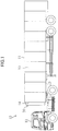
- a trailer refrigerating apparatus (20) of the present embodiment is mounted in a refrigerated vehicle (10) for transporting frozen food, fresh food, etc. by road or rail.
- the refrigerated vehicle (10) includes a trailer (11) in which freight such as frozen food is stored, and a tractor (12) for towing the trailer (11).
- the trailer (11) is formed in an elongated rectangular parallelepiped box shape extending in a front-back direction and opening at a front end.
- An in-compartment space (13) is formed inside the trailer (11), and frozen food, fresh food, etc. are stored in the in-compartment space (13).
- a rectangular frame-shaped opening (14) is formed at the front end of the trailer (11).
- a plurality of screw fixing portions (15) for attaching the trailer refrigerating apparatus (20) are formed in a front end surface of the opening (14). For example, eight of the plurality of screw fixing portions (15) are arranged at equal intervals in each of four sides of the opening (14).
- the trailer refrigerating apparatus (20) serves as a cooling apparatus for cooling air in the in-compartment space (13) of the refrigerated vehicle (10).
- the trailer refrigerating apparatus (20) includes a cooling unit (20a) for cooling the in-compartment space (13) of the trailer (11).
- the cooling unit (20a) includes a refrigerant circuit (21) filled with refrigerant.
- a compressor (22), a condenser (23), an expansion valve (24), and an evaporator (25) are connected together.
- refrigerant In the refrigerant circuit (21), refrigerant circulates to perform a vapor compression refrigeration cycle.
- An outside-compartment fan (26) is provided near the condenser (23).
- the condenser (23) heat is exchanged between outside-compartment (outdoor) air delivered by the outside-compartment fan (26) and refrigerant.
- An in-compartment fan (27) is provided near the evaporator (25). In the evaporator (25), heat is exchanged between in-compartment air delivered by the in-compartment fan (27) and refrigerant.
- the evaporator (25) serves as a cooling section for cooling air in the in-compartment space (13) of the trailer (11).
- the expansion valve (24) is configured so that the degree of opening of the expansion valve (24) is adjustable, and serves as a pressure reduction mechanism for reducing the pressure of refrigerant.
- the trailer refrigerating apparatus (20) includes a casing unit (31) attached to the opening (14) of the trailer (11).
- the casing unit (31) includes a front cover (32), an outside-compartment casing (50), and an in-compartment casing (33).
- the front cover (32) is detachable from a front surface of the outside-compartment casing (50).
- the front cover (32) is an arched-plate-shaped member which is curved so that a middle portion of the front cover (32) in a width direction thereof (right-left direction as viewed in FIG. 3 ) protrudes toward the front.
- Side portions (32a) at both ends of the front cover (32) in the width direction thereof are held by the outside-compartment casing (50).
- This forms machine chambers (35, 36) in each of which various components (details will be described later) are accommodated, between a rear surface of the front cover (32) and the front surface of the outside-compartment casing (50).
- a single middle inlet (32b) and two side inlets (32c) are provided in the front cover (32).
- the middle inlet (32b) is formed in substantially the center of the front cover (32).
- One of the side inlets (32c) is formed closer to a bottom and a left end of the front cover (32), and the other side inlet (32c) is formed closer to the bottom and a right end of the front cover (32).
- the outside-compartment casing (50) is provided outside the trailer (11), and serves as a main body of the casing unit (casing) (31).
- the outside-compartment casing (50) is formed in a substantially planar shape so that the outside-compartment casing (50) closes the opening (14) of the trailer (11) and is fixed to an outer edge of the opening (14).
- the outside-compartment casing (50) is made of an aluminum material.
- the outside-compartment casing (50) includes a square plate-shaped base (51) and a protrusion (52) formed in an upper portion of the base (51) (see, e.g., FIGS. 4-6 ).
- the base (51) is configured by connecting three plate-shaped separate bodies (51a, 51b, 51c) together in the vertical direction. That is, the base (51) includes the lower base portion (51a) provided closer to a bottom of the base (51), the upper base portion (51b) provided closer to a top of the base (51), and the middle base portion (51c) positioned between the lower base portion (51a) and the upper base portion (51b).
- a plurality of bolt holes (53a) into each of which a bolt (16) is inserted are formed in an outer edge portion (53) of the base (51).
- eight of the plurality of bolt holes (53a) are arranged at equal intervals in each of four sides of the outer edge portion (53) of the base (51).
- the bolts (16) each inserted into the bolt hole (53a) are screwed in the screw fixing portions (15) in a state in which the outer edge portion (53) of the base (51) and the opening (14) of the trailer (11) closely contact each other, thereby fixing the outside-compartment casing (50) to the trailer (11).
- the opening (14) of the trailer (11) is closed. That is, the outside-compartment casing (50) functions as a closing member for closing the opening (14) of the trailer (11).
- the opening (14) of the trailer (11) is reinforced by the outer edge portion (53) of the outside-compartment casing (50). That is, the outside-compartment casing (50) also functions as a reinforcing member of the opening (14) of the trailer (11).
- the protrusion (52) is made of an aluminum material so as to be integrally formed with the base (51), and protrudes from the base (51) toward the front.
- the protrusion (52) is formed in a rectangular parallelepiped box shape which has flat front and rear surfaces and opens on a rear surface side (see FIG. 6 ).
- the protrusion (52) may be made of, e.g., a resin material, and may be integrally connected to the base (51).
- the outside-compartment casing (50) includes a lower support member (54) and an upper support member (55).
- the lower support member (54) is provided closer to a lower end of the base (51), and the upper support member (55) is provided in a middle portion of the base (51) in the vertical direction (provided between the lower support member (54) and the protrusion (52)).
- Each of the support members (54, 55) includes an arch-shaped plate (54a, 55a).
- the plate (54a, 55a) defines an arc-shaped surface on a front side, and defines a flat surface along a front surface of the base (51) on a rear side.
- Each of the support members (54, 55) includes a bent portion (54b, 55b) formed by upwardly bending the plate (54a, 55a) at a rear end thereof.
- the bent portion (54b, 55b) is formed in a plate shape extending in the right-left direction.
- the bent portion (54b, 55b) is fixed to the base (51) with rivets, thereby fixing each of the support members (54, 55) to the base (51).
- a communication port (55c) is provided in a middle portion of the plate (55a) of the upper support member (55) in the right-left direction.
- the first machine chamber (35) is defined between the lower support member (54) and the upper support member (55).
- the second machine chamber (36) is defined above the upper support member (55).
- the first machine chamber (35) and the second machine chamber (36) are communicated with each other through the communication port (55c) of the upper support member (55).
- the first machine chamber (35) is communicated with the two side inlets (32c), and the second machine chamber (36) is communicated with the middle inlet (32b).
- the outside-compartment casing (50) includes two lower pillars (56) and two upper pillars (57).
- the lower pillars (56) are interposed between the lower support member (54) and the upper support member (55).
- the upper pillars (57) are interposed between the upper support member (55) and the protrusion (52).
- Each of the pillars (56, 57) is made of an aluminum material, and is formed in a vertically-extending prism shape.
- a generator (40), an engine (41), a battery (42), and a plurality of electric component boxes (43, 44) are provided in the first machine chamber (35).
- an engine support (60) which will be described later is provided, and the generator (40) and the engine (41) are mounted on the engine support (60).
- the engine (41) is for driving the generator (40)
- the generator (40) is for generating power for driving the compressors (22) etc. That is, in the first machine chamber (35), an engine generator is mounted, which is integrally formed by the generator (40) and the engine (41).
- the first electric component box (43) is provided in a space at the left of the generator (40), and the second electric component box (44) is provided in a space at the right of the engine (41).
- the two compressors (22), the condenser (23), a radiator (45), the two outside-compartment fans (26), and an electric component box (46) are provided.
- the two compressors (22) are mounted in a middle position of the upper support member (55) in the right-left direction.
- the radiator (45) and the condenser (23) are arranged in the front of the compressors (22).
- the condenser (23) is arranged so as to extend between the two upper pillars (57).
- the middle inlet (32b) of the front cover (32) is positioned in the front of the condenser (23).
- the radiator (45) is arranged in the rear of the condenser (23), and serves as an air-cooling radiator for dissipating heat from the engine (41).
- the two outside-compartment fans (26) are arranged so as to sandwich the two compressors (22). One of the two outside-compartment fans (26) is arranged closer to a left end of the upper support member (55), and the other outside-compartment fan (26) is arranged closer to a right end of the upper support member (55).
- the outside-compartment fan (26) is a so-called "propeller fan,” and a rotation shaft thereof extends in the right-left direction.
- a propeller is connected to an end portion of the rotation shaft of the outside-compartment fan (26) closer to the compressor (22), and a motor is connected to an opposite end portion.
- the third electric component box (46) is provided in a space closer to an upper right portion of the second machine chamber (36).
- the in-compartment casing (33) is provided on a rear surface side of the outside-compartment casing (50) so as to face the in-compartment space (13) of the trailer (11).
- the in-compartment casing (33) is made of, e.g., a glass fiber reinforced plastic (FRP) material.
- FRP glass fiber reinforced plastic
- the in-compartment casing (33) may be made of, e.g., other rein material or a metal material.
- the in-compartment casing (33) has a shape defined along a rear surface of the outside-compartment casing (50).
- a predetermined clearance is formed between a front surface of the in-compartment casing (33) and the rear surface of the outside-compartment casing (50), and a thermal insulator (34) is formed between the in-compartment casing (33) and the outside-compartment casing (50).
- a thermal insulator (34) is formed between the in-compartment casing (33) and the outside-compartment casing (50).
- a partition (37) is attached on a rear surface side of the in-compartment casing (33).
- the partition (37) is arranged so as to apart from each of a rear surface of the in-compartment casing (33), an upper inner wall of the trailer (11), and a lower inner wall of the trailer (11) with a predetermined distance. This forms an inlet port (37a) below the partition (37), and forms an outlet port (37b) above the partition (37).
- an internal air flow path (38) is formed between the in-compartment casing (33) and the partition (37) so as to extend between the inlet port (37a) and the outlet port (37b).
- the evaporator (25) and the in-compartment fan (27) are provided in the internal air flow path (38).
- the evaporator (25) is arranged so as to extend between the in-compartment casing (33) and the partition (37), and is supported by the in-compartment casing (33).
- the in-compartment fan (27) is provided above the evaporator (25).
- the engine support (60) on which the engine (41) and the generator (40) are mounted is provided. Specifically, the engine support (60) is mounted on an upper surface of the lower support member (54) between the two lower pillars (56) (see FIG. 4 ).
- the engine support (60) of the present embodiment is in a box shape opening on an upper side and an upper front side, and an outer shape of the engine support (60) is a substantially triangular column shape (see FIGS. 4 and 8 ).
- the engine support (60) of the present embodiment is made of an aluminum material.
- the engine support (60) includes a bottom plate (61), a rear plate (62), a pair of side plates (63), a front frame plate (64), and a pair of attachment plates (65).
- the bottom plate (61) is formed in a rectangular shape extending between the pair of lower pillars (56) in the right-left direction.
- a pair of wheel holding plates (66) and wheels (67) each held by the wheel holding plate (66) are provided on a lower surface (i.e., a lower portion of the engine support (60)) of the bottom plate (61).
- the wheel holding plate (66) is formed in, e.g., a plate-like shape extending in the front-back direction, and the wheel holding plates (66) are fixed to the lower surface of the bottom plate (61).
- the two wheel holding plates (66) are arranged parallel to each other at a predetermined interval.
- the wheel (67) is rotatable in a state in which an axial direction of the wheel (67) is along the right-left direction.
- the single wheel (67) is provided in each of the wheel holding plates (66), but two or more wheels (67) may be provided in each of the wheel holding plates (66).
- the rear plate (62) is formed in a substantially rectangular shape.
- part of the base (51) is positioned in the rear of the rear plate (62), and a contact between the rear plate (62) of the engine support (60) and the base (51) is allowed.
- a configuration may be employed, in which an opening into which the rear plate (62) is fitted is formed in part of the base (51) in the rear of the rear plate (62) and such an opening is closed by the rear plate (62).
- Each of the pair of side plates (63) is formed in a substantially right triangular shape so that an upper end portion and part of a front end portion of the side plate (63) are cut off to form flat surfaces.
- the bottom plate (61) is formed so as to extend between lower sides of the side plates (63)
- the rear plate (62) is formed so as to extend between rear sides of the side plates (63).
- the front frame plate (64) is formed so as to extend between front sides of the side plates (63) in the right-left direction.
- Each of the attachment plates (65) is formed in an elongated plate-like shape extending from an upper end to a lower end of the engine support (60), and a contact between a rear surface of the attachment plate (65) and the base (51) is allowed.
- a contact surface between each of the attachment plates (65) and part of the base (51) corresponding to the each of the attachment plates (65) is fixed by fastening members. That is, by fixing each of the attachment plates (65) and the base (51) to each other by the fastening members or canceling the foregoing fixing state, the engine support (60) is attached/detached to/from the outside-compartment casing (50).
- Each of the rail grooves (70) includes two rails (71).
- Each of the rails (71) is in a rod-like shape extending in the front-back direction, and is formed so as to have, e.g., a rectangular longitudinal section.
- a groove into which the wheel (67) is rotatably fitted is formed along the rails (71) between the adjacent two rails (71). That is, the rail grooves (70) are arranged below the engine support (60), and the wheels (67) are fitted into the rail grooves (70) extending in the front-back direction.
- the engine support (60) is drawable from the outside-compartment casing (50) in a forward direction relative a front side of the trailer (11).
- the rail groove (70) serves as a guiding member for guiding the engine support (60) in the front-back direction (described in detail later).
- the generator (40) When the generator (40) is driven by the engine (41), power is generated in the generator (40). Such power is supplied to the compressors (22), the outside-compartment fans (26), and the in-compartment fan (27). In the refrigerant circuit (21), the compressors (22) are operated to perform the refrigeration cycle.
- refrigerant compressed in the compressors (22) flows through the condenser (23).
- the condenser (23) the refrigerant is condensed by dissipating heat to outside-compartment air.
- the pressure of the condensed refrigerant is reduced when the refrigerant passes through the expansion valve (24), and the refrigerant after the pressure reduction flows through the evaporator (25).
- the evaporator (25) the refrigerant is evaporated by absorbing heat from in-compartment air. The evaporated refrigerant is recompressed in the compressors (22).
- in-compartment air of the in-compartment space (13) is sucked into the internal air flow path (38) through the inlet port (37a).
- the air sucked into the internal air flow path (38) upwardly flows and passes through the evaporator (25).
- the in-compartment air is cooled by exchanging heat with refrigerant.
- the in-compartment air cooled in the evaporator (25) flows in an in-compartment space (S) through the outlet port (37b), and is used for refrigerating/freezing freight etc.
- outside-compartment (outdoor) air is sucked into the machine chambers (35, 36). Specifically, the outside-compartment air is sucked through the two side inlets (32c) and the middle inlet (32b) of the front cover (32).
- the air introduced into the first machine chamber (35) through the left one of the two side inlets (32c) passes around the first electric component box (43). Then, the air flows above the engine support (60), and is sent to the vicinity of the generator (40) and the engine (41). Meanwhile, the air introduced into the first machine chamber (35) through the right one of the two side inlets (32c) passes around the second electric component box (44).
- the air flows above the engine support (60), and is sent to the vicinity of the engine (41) and the generator (40).
- the air flows near the engine (41) and the generator (40) the engine (41) and the generator (40) are cooled by the air.
- the air used for cooling the engine (41) and the generator (40) upwardly flows through the communication port (55c), and is sent to the second machine chamber (36).
- the air sucked into the second machine chamber (36) through the middle inlet (32b) passes through the condenser (23).
- refrigerant is condensed by dissipating heat to the outside-compartment air.
- the air passing through the condenser (23) flows around the radiator (45), and is used for cooling the radiator (45). Then, such air joins the air passing through the communication port (55c).
- the air joined together in the second machine chamber (36) is distributed in right and left directions so as to flow around the two compressors (22).
- the air distributed in the left direction passes through an opening at an upper end of the front cover (32), and then is released to an outside of the outside-compartment casing (50).
- the air distributed in the right direction passes through the third electric component box (46). Then, such air passes through the opening at the upper end of the front cover (32), and is released to the outside of the outside-compartment casing (50).
- the front cover (32) illustrated in FIG. 3 is first detached from the outside-compartment casing (50). Next, e.g., the pipes connected to the engine (41) and the generator (40) are removed. Subsequently, the fastening members are released in each of the attachment plates (65) of the engine support (60), and the engine support (60) is detached from the outside-compartment casing (50).
- the wheels (67) rotate to move the engine support (60) toward the front. In such a manner, the engine support (60) is drawn out so that the wheels (67) move along the rail grooves (70), and therefore the engine (41) and the generator (40) having a relatively-high weight can be easily and smoothly drawn out toward the front.
- a predetermined portion e.g., a portion corresponding to an injector
- the engine (41) and the generator (40) are in a position protruding toward the front relative to the outside-compartment casing (50) as illustrated in FIG. 9 .
- a predetermined portion e.g., a portion corresponding to an injector
- the engine (41) and the generator (40) is less susceptible to obstacles such as the upper support member (55) and other components upon maintenance of such a predetermined portion.
- the engine support (60) After completion of the maintenance, the engine support (60) is pushed toward the back. This allows the wheels (67) to rotate, thereby moving the engine support (60) toward the back. In such a manner, the engine support (60) is pushed so that the wheels (67) move along the rail grooves (70), and therefore the engine (41) and the generator (40) having the relatively-high weight can be easily and smoothly pushed toward the back and can be returned to an original position.
- the engine (41) and the generator (40) having the relatively-high weight can be drawn out toward the front from the outside-compartment casing (50) together with the engine support (60).
- the engine (41) and the generator (40) are less susceptible to the obstacles such as the upper support member (55) and the other components of the outside-compartment casing (50) upon the maintenance of the engine (41) and the generator (40), thereby improving working efficiency for maintenance.
- the wheels (67) are provided below the engine support (60), and the wheels (67) are fitted into the rail grooves (70).
- the wheels (67) can rotate along the rail grooves (70), and therefore the engine support (60) can be easily drawn and/or pushed.
- the engine support (60) is made of the aluminum material, the weight of the engine support (60) can be reduced. Thus, the engine support (60) can be more easily drawn and/or pushed.
- the lower support member (54) of the variation is in a shape in which a protrusion (middle portion) of the lower support member (54) is cut off. That is, the lower support member (54) of the variation is formed so as to have a cut-off space (54c) in a middle position of the lower support member (54) in a longitudinal direction.
- a first rib (72) is formed in a left portion below the lower support member (54) of the variation
- a second rib (73) is formed in a right portion below the lower support member (54) of the variation.
- the engine support (60) of the variation has a configuration different from that of the foregoing embodiment.
- the engine support (60) includes a bottom plate (81) and a rear plate (82).
- the bottom plate (81) is formed in a rectangular shape extending between the two lower pillars (56).
- the bottom plate (81) extends between right and left portions of the lower support member (54) so as to close the cut-off space (54c).
- the generator (40) and the engine (41) are mounted on the bottom plate (81).
- the rear plate (82) is configured so that a contact between the rear plate (82) and the base (51) is allowed.
- each of the bottom plate (81) and the rear plate (82) are fixed by fastening members. That is, the bottom plate (81) of the engine support (60) is fastened to the lower support member (54), and the rear plate (82) of the engine support (60) is fastened to the base (51). In such a manner, the engine support (60) is fixed to the outside-compartment casing (50).
- a pair of fork pockets (83) are provided below the engine support (60).
- the fork pocket (83) is formed in a substantially cylindrical shape extending in the front-back direction, and an internal space (83a) is formed inside the fork pocket (83).
- a longitudinal section (cross section perpendicular to an axis) of the internal space (83a) is in a rectangular shape with substantially flat upper and lower surfaces.
- the internal space (83a) serves as an engagement hole to be engaged with a fork of a forklift.
- a middle rib (84) extending in the right-left direction is provided between the fork pockets (83).
- the front cover (32) is first detached, and then, e.g., the pipes connected to the engine (41) and the generator (40) are removed as in the foregoing embodiment. Subsequently, in the engine support (60), the fastening members of the bottom plate (81) and the rear plate (82) are removed, and the engine support (60) is detached from the outside-compartment casing (50).
- each of a pair of forks (90) provided in the forklift is inserted into each of the fork pockets (83) of the engine support (60).
- the engine support (60) can be lifted by the forks (90) of the forklift, and can be drawn out toward the front. Consequently, the engine (41) and the generator (40) can be held in the position protruding toward the front relative to the outside-compartment casing (50), thereby improving the working efficiency for maintenance of the engine (41) and the generator (40).
- the present invention is useful for the trailer refrigerating apparatus for cooling the in-compartment space of the trailer.
Landscapes
- Engineering & Computer Science (AREA)
- Physics & Mathematics (AREA)
- Mechanical Engineering (AREA)
- Thermal Sciences (AREA)
- Chemical & Material Sciences (AREA)
- Combustion & Propulsion (AREA)
- General Engineering & Computer Science (AREA)
- Health & Medical Sciences (AREA)
- Public Health (AREA)
- Transportation (AREA)
- Devices That Are Associated With Refrigeration Equipment (AREA)
Claims (5)
- Appareil de réfrigération pour remorque comprenant :un boîtier (31) attaché à une ouverture (14) sur un côté avant d'une remorque (11) ;une unité de refroidissement (20a) configurée pour refroidir de l'air dans un espace dans un compartiment (13) de la remorque (11) ; etun générateur de moteur (40, 41) configuré pour alimenter en énergie l'unité de refroidissement (20a),caractérisé en ce quele boîtier (31) inclut un support de moteur (60) qui est fixé à un corps principal (50) du boîtier (31) et sur lequel le générateur de moteur (40, 41) est monté, etle support de moteur (60) peut être retiré du corps principal (50) du boîtier (31) dans une direction vers l'avant par rapport au côté avant de la remorque (11).
- Appareil de réfrigération pour remorque selon la revendication 1, dans lequel
un élément de guidage (70) pour le guidage du support de moteur (60) dans une direction avant-arrière est prévu dans le boîtier (31). - Appareil de réfrigération pour remorque selon la revendication 2, dans lequel
une roue (67) est prévue sous le support de moteur (60), et
l'élément de guidage est agencé sous le support de moteur (60) et inclut une rainure de rail (70) qui s'étend dans la direction avant-arrière et dans lequel la roue (67) est installée. - Appareil de réfrigération pour remorque selon la revendication 1, dans lequel
un espace interne (83a) s'étendant dans une direction avant-arrière et présentant une section longitudinale sensiblement rectangulaire est formé sous le support de moteur (60). - Appareil de réfrigération pour remorque selon l'une quelconque des revendications 1 à 4, dans lequel le support de moteur (60) est réalisé en un matériau d'aluminium.
Applications Claiming Priority (2)
| Application Number | Priority Date | Filing Date | Title |
|---|---|---|---|
| JP2009139513A JP5453943B2 (ja) | 2009-06-10 | 2009-06-10 | トレーラ用冷凍装置 |
| PCT/JP2010/003754 WO2010143391A1 (fr) | 2009-06-10 | 2010-06-04 | Dispositif de réfrigération pour remorque |
Publications (3)
| Publication Number | Publication Date |
|---|---|
| EP2442054A1 EP2442054A1 (fr) | 2012-04-18 |
| EP2442054A4 EP2442054A4 (fr) | 2017-11-29 |
| EP2442054B1 true EP2442054B1 (fr) | 2018-11-28 |
Family
ID=43308654
Family Applications (1)
| Application Number | Title | Priority Date | Filing Date |
|---|---|---|---|
| EP10785923.3A Not-in-force EP2442054B1 (fr) | 2009-06-10 | 2010-06-04 | Dispositif de réfrigération pour remorque |
Country Status (5)
| Country | Link |
|---|---|
| US (1) | US9132765B2 (fr) |
| EP (1) | EP2442054B1 (fr) |
| JP (1) | JP5453943B2 (fr) |
| CN (1) | CN102449415A (fr) |
| WO (1) | WO2010143391A1 (fr) |
Families Citing this family (10)
| Publication number | Priority date | Publication date | Assignee | Title |
|---|---|---|---|---|
| JP5936767B2 (ja) * | 2013-03-19 | 2016-06-22 | 三菱電機株式会社 | 車両用空調装置 |
| FR3029485B1 (fr) * | 2014-12-03 | 2018-03-16 | Alstom Transport Technologies | Dispositif aeraulique de refroidissement d'un element d'un vehicule ferroviaire et vehicule ferroviaire correspondant |
| WO2016153841A1 (fr) * | 2015-03-20 | 2016-09-29 | Carrier Corporation | Unité de réfrigération de transport avec compresseurs multiples |
| EP3072740A1 (fr) * | 2015-03-25 | 2016-09-28 | Thermo King Corporation | Unité de transport réfrigérée à profil bas |
| AT516249B1 (de) * | 2015-05-05 | 2016-04-15 | Ge Jenbacher Gmbh & Co Og | Anordnung aus einem Genset und einem Container |
| EP3440418B1 (fr) | 2016-04-05 | 2026-01-07 | Carrier Corporation | Système de tracteur et de remorque |
| JP6953250B2 (ja) * | 2017-09-15 | 2021-10-27 | 三菱重工サーマルシステムズ株式会社 | 輸送用冷凍ユニット及び輸送用冷凍ユニット組立方法 |
| CN108278839A (zh) * | 2018-02-07 | 2018-07-13 | 安徽海博家电科技有限公司 | 一种冰箱用底缸 |
| EP3537068A1 (fr) * | 2018-03-06 | 2019-09-11 | Arkema France | Système de refroidissement et réfrigérateur |
| JP7470581B2 (ja) | 2020-06-26 | 2024-04-18 | 三菱重工業株式会社 | 輸送用冷凍機械、及び輸送機械 |
Family Cites Families (18)
| Publication number | Priority date | Publication date | Assignee | Title |
|---|---|---|---|---|
| US4257240A (en) * | 1979-09-26 | 1981-03-24 | Thermo King Corporation | Container refrigeration unit |
| JPS6065587U (ja) * | 1983-10-11 | 1985-05-09 | 日本建鐵株式会社 | 冷凍冷蔵オ−プンシヨ−ケ−スの台枠 |
| JPS61194174U (fr) * | 1985-05-27 | 1986-12-03 | ||
| JPH0686976B2 (ja) | 1985-10-17 | 1994-11-02 | ダイキン工業株式会社 | コンテナ用冷凍装置 |
| JPH01189482A (ja) * | 1988-01-21 | 1989-07-28 | Mitsubishi Electric Corp | 冷蔵庫 |
| US4787215A (en) * | 1988-03-02 | 1988-11-29 | Thermo King Corporation | Transport refrigeration apparatus |
| US5739675A (en) * | 1995-12-26 | 1998-04-14 | Carrier Corporation | Removable powertray for a self contained motor generator set |
| CN2256329Y (zh) * | 1995-12-28 | 1997-06-18 | 张建明 | 移动式消防空气呼吸器补给机组 |
| US5678512A (en) * | 1996-11-29 | 1997-10-21 | Carrier Corporation | Cooling air flow system for a self contained motor generator set |
| US5927090A (en) * | 1997-10-02 | 1999-07-27 | Thermo King Corporation | Condenser and radiator air outlets |
| JP2001351162A (ja) * | 2000-06-08 | 2001-12-21 | Shibaura Mechatronics Corp | 自動販売機 |
| US6931884B2 (en) * | 2001-03-27 | 2005-08-23 | Thermo King Corporation | Undermount transport temperature control unit |
| JP2006071254A (ja) * | 2004-09-06 | 2006-03-16 | Seirei Ind Co Ltd | コンテナ用冷凍装置 |
| US7578534B2 (en) * | 2005-11-03 | 2009-08-25 | Martin Marietta Materials, Inc. | Structural panel for a refrigerated trailer comprising an integrated bulkhead structure for promoting air flow |
| JP2007309608A (ja) * | 2006-05-19 | 2007-11-29 | Daikin Ind Ltd | トレーラー用冷凍装置 |
| JP2008007136A (ja) * | 2006-06-27 | 2008-01-17 | Yanmar Co Ltd | エンジン駆動式冷凍コンテナ |
| CN101573244B (zh) * | 2006-07-20 | 2013-01-02 | 开利公司 | 在低温环境中运行的运输制冷单元的改进加热 |
| JP2009052833A (ja) * | 2007-08-28 | 2009-03-12 | Daikin Ind Ltd | トレーラ用冷凍装置 |
-
2009
- 2009-06-10 JP JP2009139513A patent/JP5453943B2/ja not_active Expired - Fee Related
-
2010
- 2010-06-04 EP EP10785923.3A patent/EP2442054B1/fr not_active Not-in-force
- 2010-06-04 WO PCT/JP2010/003754 patent/WO2010143391A1/fr not_active Ceased
- 2010-06-04 CN CN2010800250632A patent/CN102449415A/zh active Pending
- 2010-06-04 US US13/377,344 patent/US9132765B2/en not_active Expired - Fee Related
Non-Patent Citations (1)
| Title |
|---|
| None * |
Also Published As
| Publication number | Publication date |
|---|---|
| EP2442054A4 (fr) | 2017-11-29 |
| US20120090342A1 (en) | 2012-04-19 |
| CN102449415A (zh) | 2012-05-09 |
| US9132765B2 (en) | 2015-09-15 |
| EP2442054A1 (fr) | 2012-04-18 |
| JP2010286155A (ja) | 2010-12-24 |
| WO2010143391A1 (fr) | 2010-12-16 |
| JP5453943B2 (ja) | 2014-03-26 |
Similar Documents
| Publication | Publication Date | Title |
|---|---|---|
| EP2442054B1 (fr) | Dispositif de réfrigération pour remorque | |
| EP2436543B1 (fr) | Dispositif de réfrigération pour remorque | |
| EP2019274B1 (fr) | Dispositif de réfrigération pour remorque | |
| EP2439473B1 (fr) | Dispositif de réfrigération pour remorque | |
| JP6445406B2 (ja) | 自動車用の車体下部ユニット | |
| JP2009052833A (ja) | トレーラ用冷凍装置 | |
| KR101317284B1 (ko) | 냉동탑차의 듀얼 압축기 결합 장치 | |
| US9285158B2 (en) | Trailer refrigerating apparatus | |
| WO2014013636A1 (fr) | Réfrigérateur | |
| JP5476805B2 (ja) | トレーラ用冷凍装置 | |
| EP3261866B1 (fr) | Unité de réfrigération de transport | |
| CN202448813U (zh) | 普通冷藏车运输用制冷装置 | |
| JP2009210182A (ja) | 車両用冷凍装置 | |
| JP5476813B2 (ja) | トレーラ用冷凍装置 | |
| JP7668893B2 (ja) | 輸送用冷凍機ユニット | |
| JP5588728B2 (ja) | 車載用冷凍装置のフレーム構造 | |
| US20240369282A1 (en) | Electrical transport refrigeration unit | |
| JP2011011643A (ja) | トレーラ用冷凍装置 | |
| HK1179222A1 (zh) | 车载用制冷装置的框架结构 | |
| JP2019069643A (ja) | 車両 | |
| JP2019069641A (ja) | 車両 | |
| HK1179222B (en) | Frame structure for vehicle-mounted refrigerating device |
Legal Events
| Date | Code | Title | Description |
|---|---|---|---|
| PUAI | Public reference made under article 153(3) epc to a published international application that has entered the european phase |
Free format text: ORIGINAL CODE: 0009012 |
|
| 17P | Request for examination filed |
Effective date: 20111228 |
|
| AK | Designated contracting states |
Kind code of ref document: A1 Designated state(s): AL AT BE BG CH CY CZ DE DK EE ES FI FR GB GR HR HU IE IS IT LI LT LU LV MC MK MT NL NO PL PT RO SE SI SK SM TR |
|
| RAP1 | Party data changed (applicant data changed or rights of an application transferred) |
Owner name: DAIKIN INDUSTRIES, LTD. Owner name: SCHMITZ CARGOBULL AG |
|
| DAX | Request for extension of the european patent (deleted) | ||
| RA4 | Supplementary search report drawn up and despatched (corrected) |
Effective date: 20171026 |
|
| RIC1 | Information provided on ipc code assigned before grant |
Ipc: B60P 3/20 20060101ALI20171020BHEP Ipc: F25D 11/00 20060101ALI20171020BHEP Ipc: F25D 19/00 20060101AFI20171020BHEP |
|
| GRAP | Despatch of communication of intention to grant a patent |
Free format text: ORIGINAL CODE: EPIDOSNIGR1 |
|
| STAA | Information on the status of an ep patent application or granted ep patent |
Free format text: STATUS: GRANT OF PATENT IS INTENDED |
|
| RIC1 | Information provided on ipc code assigned before grant |
Ipc: B60P 3/20 20060101ALI20180618BHEP Ipc: F25D 19/00 20060101AFI20180618BHEP Ipc: F25D 11/00 20060101ALI20180618BHEP |
|
| INTG | Intention to grant announced |
Effective date: 20180703 |
|
| GRAS | Grant fee paid |
Free format text: ORIGINAL CODE: EPIDOSNIGR3 |
|
| GRAA | (expected) grant |
Free format text: ORIGINAL CODE: 0009210 |
|
| STAA | Information on the status of an ep patent application or granted ep patent |
Free format text: STATUS: THE PATENT HAS BEEN GRANTED |
|
| AK | Designated contracting states |
Kind code of ref document: B1 Designated state(s): AL AT BE BG CH CY CZ DE DK EE ES FI FR GB GR HR HU IE IS IT LI LT LU LV MC MK MT NL NO PL PT RO SE SI SK SM TR |
|
| REG | Reference to a national code |
Ref country code: GB Ref legal event code: FG4D |
|
| REG | Reference to a national code |
Ref country code: CH Ref legal event code: EP |
|
| REG | Reference to a national code |
Ref country code: AT Ref legal event code: REF Ref document number: 1070697 Country of ref document: AT Kind code of ref document: T Effective date: 20181215 |
|
| REG | Reference to a national code |
Ref country code: DE Ref legal event code: R096 Ref document number: 602010055476 Country of ref document: DE |
|
| REG | Reference to a national code |
Ref country code: IE Ref legal event code: FG4D |
|
| REG | Reference to a national code |
Ref country code: NL Ref legal event code: MP Effective date: 20181128 |
|
| REG | Reference to a national code |
Ref country code: LT Ref legal event code: MG4D |
|
| REG | Reference to a national code |
Ref country code: AT Ref legal event code: MK05 Ref document number: 1070697 Country of ref document: AT Kind code of ref document: T Effective date: 20181128 |
|
| PG25 | Lapsed in a contracting state [announced via postgrant information from national office to epo] |
Ref country code: FI Free format text: LAPSE BECAUSE OF FAILURE TO SUBMIT A TRANSLATION OF THE DESCRIPTION OR TO PAY THE FEE WITHIN THE PRESCRIBED TIME-LIMIT Effective date: 20181128 Ref country code: AT Free format text: LAPSE BECAUSE OF FAILURE TO SUBMIT A TRANSLATION OF THE DESCRIPTION OR TO PAY THE FEE WITHIN THE PRESCRIBED TIME-LIMIT Effective date: 20181128 Ref country code: LT Free format text: LAPSE BECAUSE OF FAILURE TO SUBMIT A TRANSLATION OF THE DESCRIPTION OR TO PAY THE FEE WITHIN THE PRESCRIBED TIME-LIMIT Effective date: 20181128 Ref country code: HR Free format text: LAPSE BECAUSE OF FAILURE TO SUBMIT A TRANSLATION OF THE DESCRIPTION OR TO PAY THE FEE WITHIN THE PRESCRIBED TIME-LIMIT Effective date: 20181128 Ref country code: LV Free format text: LAPSE BECAUSE OF FAILURE TO SUBMIT A TRANSLATION OF THE DESCRIPTION OR TO PAY THE FEE WITHIN THE PRESCRIBED TIME-LIMIT Effective date: 20181128 Ref country code: NO Free format text: LAPSE BECAUSE OF FAILURE TO SUBMIT A TRANSLATION OF THE DESCRIPTION OR TO PAY THE FEE WITHIN THE PRESCRIBED TIME-LIMIT Effective date: 20190228 Ref country code: IS Free format text: LAPSE BECAUSE OF FAILURE TO SUBMIT A TRANSLATION OF THE DESCRIPTION OR TO PAY THE FEE WITHIN THE PRESCRIBED TIME-LIMIT Effective date: 20190328 Ref country code: ES Free format text: LAPSE BECAUSE OF FAILURE TO SUBMIT A TRANSLATION OF THE DESCRIPTION OR TO PAY THE FEE WITHIN THE PRESCRIBED TIME-LIMIT Effective date: 20181128 Ref country code: BG Free format text: LAPSE BECAUSE OF FAILURE TO SUBMIT A TRANSLATION OF THE DESCRIPTION OR TO PAY THE FEE WITHIN THE PRESCRIBED TIME-LIMIT Effective date: 20190228 |
|
| PG25 | Lapsed in a contracting state [announced via postgrant information from national office to epo] |
Ref country code: AL Free format text: LAPSE BECAUSE OF FAILURE TO SUBMIT A TRANSLATION OF THE DESCRIPTION OR TO PAY THE FEE WITHIN THE PRESCRIBED TIME-LIMIT Effective date: 20181128 Ref country code: SE Free format text: LAPSE BECAUSE OF FAILURE TO SUBMIT A TRANSLATION OF THE DESCRIPTION OR TO PAY THE FEE WITHIN THE PRESCRIBED TIME-LIMIT Effective date: 20181128 Ref country code: PT Free format text: LAPSE BECAUSE OF FAILURE TO SUBMIT A TRANSLATION OF THE DESCRIPTION OR TO PAY THE FEE WITHIN THE PRESCRIBED TIME-LIMIT Effective date: 20190328 Ref country code: GR Free format text: LAPSE BECAUSE OF FAILURE TO SUBMIT A TRANSLATION OF THE DESCRIPTION OR TO PAY THE FEE WITHIN THE PRESCRIBED TIME-LIMIT Effective date: 20190301 |
|
| PG25 | Lapsed in a contracting state [announced via postgrant information from national office to epo] |
Ref country code: NL Free format text: LAPSE BECAUSE OF FAILURE TO SUBMIT A TRANSLATION OF THE DESCRIPTION OR TO PAY THE FEE WITHIN THE PRESCRIBED TIME-LIMIT Effective date: 20181128 |
|
| PG25 | Lapsed in a contracting state [announced via postgrant information from national office to epo] |
Ref country code: CZ Free format text: LAPSE BECAUSE OF FAILURE TO SUBMIT A TRANSLATION OF THE DESCRIPTION OR TO PAY THE FEE WITHIN THE PRESCRIBED TIME-LIMIT Effective date: 20181128 Ref country code: PL Free format text: LAPSE BECAUSE OF FAILURE TO SUBMIT A TRANSLATION OF THE DESCRIPTION OR TO PAY THE FEE WITHIN THE PRESCRIBED TIME-LIMIT Effective date: 20181128 Ref country code: DK Free format text: LAPSE BECAUSE OF FAILURE TO SUBMIT A TRANSLATION OF THE DESCRIPTION OR TO PAY THE FEE WITHIN THE PRESCRIBED TIME-LIMIT Effective date: 20181128 |
|
| REG | Reference to a national code |
Ref country code: DE Ref legal event code: R097 Ref document number: 602010055476 Country of ref document: DE |
|
| PG25 | Lapsed in a contracting state [announced via postgrant information from national office to epo] |
Ref country code: SK Free format text: LAPSE BECAUSE OF FAILURE TO SUBMIT A TRANSLATION OF THE DESCRIPTION OR TO PAY THE FEE WITHIN THE PRESCRIBED TIME-LIMIT Effective date: 20181128 Ref country code: RO Free format text: LAPSE BECAUSE OF FAILURE TO SUBMIT A TRANSLATION OF THE DESCRIPTION OR TO PAY THE FEE WITHIN THE PRESCRIBED TIME-LIMIT Effective date: 20181128 Ref country code: EE Free format text: LAPSE BECAUSE OF FAILURE TO SUBMIT A TRANSLATION OF THE DESCRIPTION OR TO PAY THE FEE WITHIN THE PRESCRIBED TIME-LIMIT Effective date: 20181128 Ref country code: SM Free format text: LAPSE BECAUSE OF FAILURE TO SUBMIT A TRANSLATION OF THE DESCRIPTION OR TO PAY THE FEE WITHIN THE PRESCRIBED TIME-LIMIT Effective date: 20181128 |
|
| PLBE | No opposition filed within time limit |
Free format text: ORIGINAL CODE: 0009261 |
|
| STAA | Information on the status of an ep patent application or granted ep patent |
Free format text: STATUS: NO OPPOSITION FILED WITHIN TIME LIMIT |
|
| PG25 | Lapsed in a contracting state [announced via postgrant information from national office to epo] |
Ref country code: SI Free format text: LAPSE BECAUSE OF FAILURE TO SUBMIT A TRANSLATION OF THE DESCRIPTION OR TO PAY THE FEE WITHIN THE PRESCRIBED TIME-LIMIT Effective date: 20181128 |
|
| 26N | No opposition filed |
Effective date: 20190829 |
|
| PG25 | Lapsed in a contracting state [announced via postgrant information from national office to epo] |
Ref country code: MC Free format text: LAPSE BECAUSE OF FAILURE TO SUBMIT A TRANSLATION OF THE DESCRIPTION OR TO PAY THE FEE WITHIN THE PRESCRIBED TIME-LIMIT Effective date: 20181128 |
|
| REG | Reference to a national code |
Ref country code: CH Ref legal event code: PL |
|
| GBPC | Gb: european patent ceased through non-payment of renewal fee |
Effective date: 20190604 |
|
| REG | Reference to a national code |
Ref country code: BE Ref legal event code: MM Effective date: 20190630 |
|
| PG25 | Lapsed in a contracting state [announced via postgrant information from national office to epo] |
Ref country code: TR Free format text: LAPSE BECAUSE OF FAILURE TO SUBMIT A TRANSLATION OF THE DESCRIPTION OR TO PAY THE FEE WITHIN THE PRESCRIBED TIME-LIMIT Effective date: 20181128 |
|
| PG25 | Lapsed in a contracting state [announced via postgrant information from national office to epo] |
Ref country code: IE Free format text: LAPSE BECAUSE OF NON-PAYMENT OF DUE FEES Effective date: 20190604 Ref country code: GB Free format text: LAPSE BECAUSE OF NON-PAYMENT OF DUE FEES Effective date: 20190604 |
|
| PG25 | Lapsed in a contracting state [announced via postgrant information from national office to epo] |
Ref country code: LI Free format text: LAPSE BECAUSE OF NON-PAYMENT OF DUE FEES Effective date: 20190630 Ref country code: BE Free format text: LAPSE BECAUSE OF NON-PAYMENT OF DUE FEES Effective date: 20190630 Ref country code: CH Free format text: LAPSE BECAUSE OF NON-PAYMENT OF DUE FEES Effective date: 20190630 Ref country code: LU Free format text: LAPSE BECAUSE OF NON-PAYMENT OF DUE FEES Effective date: 20190604 |
|
| PG25 | Lapsed in a contracting state [announced via postgrant information from national office to epo] |
Ref country code: FR Free format text: LAPSE BECAUSE OF NON-PAYMENT OF DUE FEES Effective date: 20190630 |
|
| PG25 | Lapsed in a contracting state [announced via postgrant information from national office to epo] |
Ref country code: CY Free format text: LAPSE BECAUSE OF FAILURE TO SUBMIT A TRANSLATION OF THE DESCRIPTION OR TO PAY THE FEE WITHIN THE PRESCRIBED TIME-LIMIT Effective date: 20181128 |
|
| PG25 | Lapsed in a contracting state [announced via postgrant information from national office to epo] |
Ref country code: HU Free format text: LAPSE BECAUSE OF FAILURE TO SUBMIT A TRANSLATION OF THE DESCRIPTION OR TO PAY THE FEE WITHIN THE PRESCRIBED TIME-LIMIT; INVALID AB INITIO Effective date: 20100604 Ref country code: MT Free format text: LAPSE BECAUSE OF FAILURE TO SUBMIT A TRANSLATION OF THE DESCRIPTION OR TO PAY THE FEE WITHIN THE PRESCRIBED TIME-LIMIT Effective date: 20181128 |
|
| PG25 | Lapsed in a contracting state [announced via postgrant information from national office to epo] |
Ref country code: MK Free format text: LAPSE BECAUSE OF FAILURE TO SUBMIT A TRANSLATION OF THE DESCRIPTION OR TO PAY THE FEE WITHIN THE PRESCRIBED TIME-LIMIT Effective date: 20181128 |
|
| P01 | Opt-out of the competence of the unified patent court (upc) registered |
Effective date: 20230525 |
|
| PGFP | Annual fee paid to national office [announced via postgrant information from national office to epo] |
Ref country code: DE Payment date: 20230620 Year of fee payment: 14 |
|
| PGFP | Annual fee paid to national office [announced via postgrant information from national office to epo] |
Ref country code: IT Payment date: 20230623 Year of fee payment: 14 |
|
| REG | Reference to a national code |
Ref country code: DE Ref legal event code: R119 Ref document number: 602010055476 Country of ref document: DE |
|
| PG25 | Lapsed in a contracting state [announced via postgrant information from national office to epo] |
Ref country code: DE Free format text: LAPSE BECAUSE OF NON-PAYMENT OF DUE FEES Effective date: 20250101 |
|
| PG25 | Lapsed in a contracting state [announced via postgrant information from national office to epo] |
Ref country code: IT Free format text: LAPSE BECAUSE OF NON-PAYMENT OF DUE FEES Effective date: 20240604 |