WO2010143391A1 - Dispositif de réfrigération pour remorque - Google Patents
Dispositif de réfrigération pour remorque Download PDFInfo
- Publication number
- WO2010143391A1 WO2010143391A1 PCT/JP2010/003754 JP2010003754W WO2010143391A1 WO 2010143391 A1 WO2010143391 A1 WO 2010143391A1 JP 2010003754 W JP2010003754 W JP 2010003754W WO 2010143391 A1 WO2010143391 A1 WO 2010143391A1
- Authority
- WO
- WIPO (PCT)
- Prior art keywords
- trailer
- engine
- casing
- engine support
- generator
- Prior art date
- Legal status (The legal status is an assumption and is not a legal conclusion. Google has not performed a legal analysis and makes no representation as to the accuracy of the status listed.)
- Ceased
Links
Images






Classifications
-
- B—PERFORMING OPERATIONS; TRANSPORTING
- B60—VEHICLES IN GENERAL
- B60P—VEHICLES ADAPTED FOR LOAD TRANSPORTATION OR TO TRANSPORT, TO CARRY, OR TO COMPRISE SPECIAL LOADS OR OBJECTS
- B60P3/00—Vehicles adapted to transport, to carry or to comprise special loads or objects
- B60P3/20—Refrigerated goods vehicles
-
- F—MECHANICAL ENGINEERING; LIGHTING; HEATING; WEAPONS; BLASTING
- F25—REFRIGERATION OR COOLING; COMBINED HEATING AND REFRIGERATION SYSTEMS; HEAT PUMP SYSTEMS; MANUFACTURE OR STORAGE OF ICE; LIQUEFACTION SOLIDIFICATION OF GASES
- F25D—REFRIGERATORS; COLD ROOMS; ICE-BOXES; COOLING OR FREEZING APPARATUS NOT OTHERWISE PROVIDED FOR
- F25D11/00—Self-contained movable devices, e.g. domestic refrigerators
- F25D11/003—Transport containers
-
- F—MECHANICAL ENGINEERING; LIGHTING; HEATING; WEAPONS; BLASTING
- F25—REFRIGERATION OR COOLING; COMBINED HEATING AND REFRIGERATION SYSTEMS; HEAT PUMP SYSTEMS; MANUFACTURE OR STORAGE OF ICE; LIQUEFACTION SOLIDIFICATION OF GASES
- F25B—REFRIGERATION MACHINES, PLANTS OR SYSTEMS; COMBINED HEATING AND REFRIGERATION SYSTEMS; HEAT PUMP SYSTEMS
- F25B2500/00—Problems to be solved
- F25B2500/06—Damage
Definitions
- the present invention relates to a trailer refrigeration apparatus that cools the interior space of a trailer.
- Patent Document 1 discloses this type of trailer refrigeration apparatus.
- the trailer refrigeration apparatus has a casing attached to the open portion of the front end of the trailer and a cooling unit that is supported by the casing and cools the inside of the warehouse.
- the cooling unit is composed of an evaporator connected to the refrigerant circuit.
- the refrigerant circulates in the refrigerant circuit to perform a vapor compression refrigeration cycle.
- the refrigerant absorbs heat from the store air and evaporates, and as a result, the store air is cooled.
- an engine generator is installed on the support part of the casing.
- a casing main body portion that closes the trailer is provided with a plurality of frame members extending in the horizontal direction and the vertical direction to reinforce the casing.
- the engine generator is installed in the frame-shaped support part extended horizontally among these frame parts.
- the present invention has been made in view of such a point, and an object thereof is to provide a trailer refrigeration apparatus capable of maintaining an engine generator quickly and easily.
- the first invention comprises a casing (31) attached to the front opening (14) of the trailer (11), a cooling unit (20a) for cooling the air in the interior space (13) of the trailer (11), An engine generator (40, 41) for supplying electric power to the cooling unit (20a), and the casing (31) is fixed to the main body (50) of the casing (31) and the engine A trailer refrigeration system having an engine support (60) on which a generator (40, 41) is installed is targeted.
- the engine support portion (60) is configured to be freely drawn out in the direction toward the front side of the trailer (11) with respect to the main body portion (50) of the casing (31).
- the trailer (11) is closed by attaching the casing (31) to the opening (14) on the front side of the trailer (11).
- the engine generator (40, 41) When the engine generator (40, 41) is operated, electric power is supplied to the cooling unit (20a).
- the cooling unit (20a) By operating the cooling unit (20a), the interior space (13) of the trailer (11) is cooled.
- the engine support (60) on which the engine generator (40, 41) is installed can be drawn forward with respect to the main body (50) of the casing (31). Thereby, when a user etc. maintain an engine generator (40, 41), an engine support part (60) can be pulled ahead with an engine generator (40, 41). For this reason, since the engine generator (40, 41) is positioned in front of the main body (50), the reinforcement provided in the main body (50) during maintenance of the engine generator (40, 41). It is suppressed that a member and other component parts get in the way.
- the engine generator (40, 41) is pulled forward together with the engine support (60), the engine generator (40, 41) having a relatively large weight can be easily pulled forward.
- the second invention is characterized in that, in the first invention, the casing (31) is provided with a guide member (70) for guiding the engine support portion (60) back and forth.
- the guide member (70) is provided in the casing (31).
- this engine support part (60) can be pulled out forward, guiding the engine support part (60) to the guide member (70). Therefore, the engine generator (40, 41) having a relatively large weight can be easily pulled forward.
- the engine support (60) can be pushed backward while the engine support (60) is guided by the guide member (70). Therefore, the engine generator (40, 41) having a relatively large weight can be easily returned to the original position.
- a wheel portion (67) is provided at a lower portion of the engine support portion (60), and the guide member is arranged below the engine support portion (60). It is provided and has a rail groove part (70) extended in the front-back direction and the said wheel part (67) fitting.
- the wheel part (67) provided at the lower part of the engine support part (60) is fitted into the rail groove part (70).
- an engine support part (60) can be pulled out ahead, rolling a wheel part (67) along a rail groove part (70). Therefore, the engine generator (40, 41) having a relatively large weight can be easily and smoothly pulled forward.
- the engine support portion (60) can be pushed rearward while rolling the wheel portion (67) along the rail groove portion (70). Therefore, the engine generator (40, 41) having a relatively large weight can be easily returned to the original position.
- a fourth invention is characterized in that, in the first invention, an internal space (83a) extending in the front-rear direction and having a substantially rectangular cross section is formed in the lower part of the engine support part (60). To do.
- an internal space (83a) is formed in the lower portion thereof.
- the internal space (83a) extends in the front-rear direction, and its longitudinal section is formed in a substantially rectangular shape. For this reason, by inserting a claw such as a forklift into this internal space (83a), the engine support (60) can be pulled forward while being supported by the forklift.
- the fifth invention is characterized in that, in any one of the first to fourth inventions, the engine support portion (60) is made of an aluminum material.
- the engine support portion (60) is made of an aluminum material, whereby the weight of the engine support portion (60) can be reduced. For this reason, at the time of maintenance of an engine generator (40, 41), an engine support part (60) can be pulled out more simply.
- the engine generator (40, 41) having a relatively large weight can be pulled forward together with the engine support (60) with respect to the main body (50) of the casing (31). Therefore, during maintenance of the engine generator (40, 41), it is possible to suppress the obstruction of the reinforcing member and other components arranged in the main body (50), and the maintenance work efficiency can be improved.
- the engine support portion (60) can be guided back and forth by the guide member (70), so that the engine support portion (60) can be pulled out and pushed in easily and reliably. .
- the wheel portion (67) is provided at the lower portion of the engine support portion (60), and the wheel portion (67) can be rotated along the rail groove portion (70). For this reason, the operation of pulling out / pushing in the engine support portion (60) is further facilitated.
- the forklift pawl can be inserted into the internal space (83a). Therefore, the engine support portion (60) can be pulled forward by the forklift.
- the engine support portion (60) is made of an aluminum material, the weight of the engine support portion (60) can be reduced. Accordingly, the pulling / pushing-in operation of the engine support part (60) can be performed more easily and reliably.
- FIG. 1 is an overall configuration diagram of a refrigeration vehicle and a trailer refrigeration apparatus.
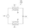
- FIG. 2 is a schematic configuration diagram of a refrigerant circuit of the trailer refrigeration apparatus.
- FIG. 3 is a perspective view showing the entire configuration of the trailer opening and the trailer refrigeration apparatus.
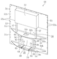
- FIG. 4 is a perspective view of the outer casing.
- FIG. 5 is a perspective view showing the trailer refrigeration apparatus with the front cover removed.
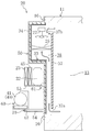
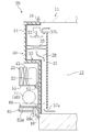
- FIG. 6 is a longitudinal sectional view showing a schematic configuration of the trailer refrigeration apparatus.
- FIG. 7 is a perspective view illustrating the trailer refrigeration apparatus with the front cover removed, and illustrates the flow of outdoor air.
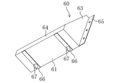
- FIG. 8 is a perspective view of the engine support portion according to the embodiment.
- FIG. 8 is a perspective view of the engine support portion according to the embodiment.
- FIG. 9 is a longitudinal sectional view showing a schematic configuration of the trailer refrigeration apparatus, and shows a state in which the engine support portion is pulled out to the front side.
- FIG. 10 is a perspective view of a modified external casing.
- FIG. 11 is a longitudinal sectional view showing a schematic configuration of a trailer refrigeration apparatus according to a modification.
- FIG. 12 is a longitudinal sectional view showing a schematic configuration of a trailer refrigeration apparatus according to a modified example, and shows a state in which the engine support portion is pulled out to the front side.
- the trailer refrigeration apparatus (20) of this embodiment is mounted on a refrigeration vehicle (10) for transporting frozen foods, fresh foods, and the like on land.
- the refrigeration vehicle (10) includes a trailer (11) that stores cargo such as frozen food, and a tractor (12) that pulls the trailer (11).
- the trailer (11) is formed in a box shape having a vertically long rectangular parallelepiped shape in the front-rear direction and an open front end.
- An interior space (13) is formed inside the trailer (11), and frozen food, fresh food, and the like are stored in the interior space (13).
- a rectangular frame-shaped opening (14) is formed at the front end of the trailer (11).
- a plurality of screwing portions (15, 15,%) are formed on the front end surface of the opening portion (14).
- the plurality of screwing portions (15, 15,...) Are arranged at regular intervals, for example, at 8 locations on each of the four sides of the opening portion (14).
- the trailer refrigeration apparatus (20) constitutes a cooling apparatus for cooling the air in the internal space (13) of the refrigeration vehicle (10).
- the trailer refrigeration apparatus (20) includes a cooling unit (20a) for cooling the internal space (13) of the trailer (11).
- the cooling unit (20a) includes a refrigerant circuit (21) filled with a refrigerant.
- a compressor (22), a condenser (23), an expansion valve (24), and an evaporator (25) are connected to the refrigerant circuit (21).
- a refrigerant is circulated to perform a vapor compression refrigeration cycle.
- An outside fan (26) is provided in the vicinity of the condenser (23).
- An internal fan (27) is provided in the vicinity of the evaporator (25). In the evaporator (25), the internal air conveyed by the internal fan (27) and the refrigerant exchange heat.
- the evaporator (25) constitutes a cooling unit for cooling the air in the interior space (13) of the trailer (11).
- the expansion valve (24) is configured such that the opening degree can be adjusted, and constitutes a decompression mechanism for decompressing the refrigerant.
- the trailer refrigerating apparatus (20) has a casing unit (31) attached to the open portion (14) of the trailer (11).
- the casing unit (31) includes a front cover (32), an external casing (50), and an internal casing (33).
- the front cover (32) is configured to be detachable from the front surface of the external casing (50).
- the front cover (32) is configured by an arcuate plate-like member in which an intermediate portion in the width direction (left-right direction in FIG. 3) bulges forward.
- the side part (32a, 32a) of the width direction both ends is hold
- the front cover (32) is provided with one central inlet (32b) and two side inlets (32c, 32c).
- the central introduction port (32b) is formed in the approximate center of the front cover (32).
- the side introduction ports (32c, 32c) are formed on the lower side of the front cover (32) and on the left and right ends, respectively.
- the outside casing (50) is provided outside the trailer (11) and constitutes a main body of the casing unit (casing) (31).
- the outside-compartment casing (50) is formed in a substantially planar shape that closes the open portion (14) of the trailer (11) and is fixed to the outer edge of the open portion (14).
- the outside casing (50) is made of an aluminum material.
- the outside casing (50) has a square plate-shaped base portion (51) and a bulging portion (52) formed in an upper portion of the base portion (51) (for example, FIG. 4 to FIG. 6).
- the base part (51) is configured by connecting three plate-like divided bodies (51a, 51b, 51c) in the vertical direction. That is, the base part (51) is located between the lower base part (51a) near the lower part, the upper base part (51b) near the upper part, and the lower base part (51a) and the upper base part (51b). It is comprised by the intermediate base part (51c) located.
- a plurality of bolt holes (53a, 53a,%) Through which the bolts (16) are inserted are formed in the outer edge portion (53) of the base portion (51).
- the plurality of bolt holes (53a, 53a,...) are arranged at equal intervals, for example, at eight locations on each of the four sides of the outer edge portion (53) of the base portion (51).
- the outer casing (50) is a bolt (16) that penetrates the bolt hole (53a) with the outer edge (53) of the base part (51) and the open part (14) of the trailer (11) in close contact with each other. Is fixed to the trailer (11) by fastening it to the screwing portion (15).
- the open part (14) of the trailer (11) is closed. That is, the outside casing (50) functions as a closing member that closes the opening (14) of the trailer (11). Moreover, in the state which fixed the outer casing (50) to the trailer (11), the open part (14) of the trailer (11) is reinforced by the outer edge part (53) of the outer casing (50). That is, the outside casing (50) also functions as a reinforcing member for the open portion (14) of the trailer (11).
- the bulging portion (52) is made of an aluminum material that is integral with the base portion (51), and bulges forward from the base portion (51).
- the bulging portion (52) is formed in a box shape having a rectangular parallelepiped shape that is flat in the front-rear direction and opened on the rear surface side (see FIG. 6).
- the bulging portion (52) may be made of, for example, a resin material and integrally connected to the base portion (51).
- the outer casing (50) includes a lower support member (54) and an upper support member (55).
- the lower support member (54) is provided near the lower end of the base portion (51), and the upper support member (55) is swelled with an intermediate portion (lower support member (54) in the vertical direction of the base portion (51). (Between the outlet (52)).
- Each support member (54, 55) has an arcuate plate-like plate portion (54a, 55a).
- the plate portions (54a, 55a) are formed in a circular arc shape on the front side and linearly on the rear side along the front surface of the base portion (51).
- Each support member (54, 55) has a bent portion (54b, 55b) bent upward from the rear end of the plate portion (54a, 55a).
- the bent portions (54b, 55b) are formed in a plate shape extending in the left-right direction.
- Each support member (54, 55) is fixed to the base portion (51) by the bent portions (54b, 55b) being fixed to the base portion (51) by rivets.
- the plate portion (55a) of the upper support member (55) is provided with a communication port (55c) at an intermediate portion in the left-right direction.
- the first machine chamber (35) is partitioned between the lower support member (54) and the upper support member (55).
- a second machine chamber (36) is defined above the upper support member (55).
- the first machine chamber (35) and the second machine chamber (36) communicate with each other via the communication port (55c) of the upper support member (55).
- the first machine room (35) communicates with the two side introduction ports (32c, 32c) described above, and the second machine room (36) communicates with the center introduction port (32b) described above. .
- the outer casing (50) includes two lower pillars (56) and two upper pillars (57).
- the lower column portion (56) is interposed between the lower support member (54) and the upper support member (55).
- the upper column part (57) is interposed between the upper support member (55) and the bulging part (52).
- Each column portion (56, 57) is made of an aluminum material and is formed in a prismatic shape extending vertically.
- a generator (40), an engine (41), a battery (42), and a plurality of electrical component boxes (43, 44) are provided in the first machine room (35) described above. Yes.
- the first machine room (35) is provided with an engine support part (60), which will be described in detail later.
- a generator (40) and an engine (41) are installed on the engine support part (60). Yes.
- the engine (41) drives the generator (40), and the generator (40) generates electric power for driving the above-described compressor (22) and the like. That is, an engine generator in which the generator (40) and the engine (41) are integrally formed is mounted in the first machine room (35).
- the first electrical component box (43) is provided in the left space of the generator (40), and the second electrical component box (in the right space of the engine (41) ( 44) is provided.
- the second machine room (36) is provided with two compressors (22), a condenser (23), a radiator (45), two external fans (26), and an electrical component box (46).
- two compressors (22) are installed at an intermediate position in the left-right direction of the upper support member (55).
- a radiator (45) and a condenser (23) are disposed in front of the compressor (22).
- the condenser (23) is disposed so as to straddle the two upper pillars (57).
- the central inlet (32b) of the front cover (32) is located in front of the condenser (23).
- the radiator (45) is disposed on the rear side of the condenser (23), and constitutes an air-cooled radiator for radiating heat from the engine (41).
- the two external fans (26, 26) are arranged near the left and right ends of the upper support member (55) so as to sandwich the two compressors (22).
- the external fan (2) is a so-called propeller fan, and its rotation shaft extends to the left and right.
- a propeller is connected to the end near the compressor (22) and a motor is connected to the opposite end of the rotating shaft of the external fan (26).
- a third electrical component box (46) is provided in the space on the upper right side.
- the internal casing (33) is provided on the back side of the external casing (50) so as to face the internal space (13) of the trailer (11).
- the internal casing (33) is made of, for example, an FRP (glass fiber reinforced plastic) material. Note that the internal casing (33) can be made of other resin material, metal material, or the like.
- the internal casing (33) has a shape along the back surface of the external casing (50).
- the front surface of the inner casing (33) is spaced a predetermined distance from the rear surface of the outer casing (50), and a heat insulating member (34) is provided between the inner casing (33) and the outer casing (50). Is formed.
- the heat insulating member (34) is integrated with the casing unit (31) by forming a sealed space between the outer casing (50) and the inner casing (33) and then filling the sealed space with foamed resin. Formed.
- a partition member (37) is attached to the back side of the internal casing (33).
- the partition member (37) is disposed so as to have a predetermined distance from each of the back surface of the internal casing (33), the upper inner wall of the trailer (11), and the lower inner wall of the trailer (11).
- the inflow port (37a) is formed below the partition member (37)
- the outflow port (37b) is formed above the partition member (37).
- an internal air flow path (38) is formed between the internal casing (33) and the partition member (37) so as to straddle the inflow port (37a) and the outflow port (37b).
- the inside air flow path (38) is provided with the evaporator (25) and the internal fan (27) described above.
- the evaporator (25) is disposed on the back side of the bulging portion (52) so as to straddle between the inner casing (33) and the partition member (37) and supported by the inner casing (33). ing.
- the internal fan (27) is provided above the evaporator (25).
- the outer casing (50) is provided with the engine support (60) on which the engine (41) and the generator (40) are installed.
- the engine support part (60) is installed on the upper surface of the lower support member (54) between the two lower support members (54, 54) (see FIG. 4).
- the engine support portion (60) of the present embodiment has a box shape in which the upper side and the oblique front side are opened, and the outer shape is generally formed in a triangular column shape (see FIGS. 4 and 8). Moreover, the engine support part (60) of this embodiment is comprised with the aluminum material.
- the engine support portion (60) includes a bottom plate portion (61), a back plate portion (62), a pair of side plate portions (63, 63), a front frame plate portion (64), and a pair of mounting plate portions (65, 65). have.
- the bottom plate portion (61) is formed in a rectangular shape extending left and right so as to straddle the pair of lower column portions (56, 56).
- a pair of wheel holding plates (66, 66) and wheel portions held by the wheel holding portions (66, 66), respectively. (67, 67) are provided on the lower surface of the bottom plate portion (61) (that is, the lower portion of the engine support portion (60)).
- the wheel holding plates (66, 66) are formed in, for example, a plate shape extending in the front-rear direction, and are fixed to the lower surface of the bottom plate portion (61).
- the two wheel holding portions (66, 66) are arranged in parallel so as to have a predetermined interval.
- the wheel portion (67) is configured to be rotatable with the left-right direction as an axial direction.
- one wheel holding part (66) is provided with one wheel part (67), but one wheel holding part (66) is provided with two or more wheel parts (67).
- the back plate portion (62) is formed in a substantially rectangular shape.
- a part of the base part (51) described above is located on the back side of the back plate part (62), and the back plate part (62) and the base part (51) of the engine support part (60) Can be contacted.
- an opening for fitting the back plate portion (62) is formed in the back portion of the back plate portion (62) in the base portion (51), and this opening is formed by the back plate portion (62). You may employ
- the pair of side plate portions (63, 63) are formed in a substantially right triangle shape in which the upper end portion and the front end portion are notched flat. Then, the bottom plate portion (61) is formed so as to straddle the lower side of both side plate portions (63, 63), and the back plate portion ( 62) is formed. Furthermore, the said front frame board part (64) is extended and formed so that it may straddle the edge of the front end of both side board parts (63,63).
- the pair of mounting plate portions (65, 65) protrude from the side plate portions (63, 63) to the left and right outer sides of the engine support portion (60), respectively.
- Each of the mounting plate portions (65, 65) is formed in a long plate shape extending from the upper end to the lower end of the engine support portion (60), and the back surface thereof can come into contact with the base portion (51).
- the contact surfaces of the mounting plate portions (65, 65) and the base portion (51) corresponding to the mounting plate portions (65, 65) are fixed by fastening members. That is, the engine support part (60) can be attached to and detached from the external casing (50) by fixing each mounting plate part (65, 65) and the base part (51) with a fastening member or releasing the fixing. It has become.
- Each rail groove (70) has two rails (71, 71).
- Each rail (71, 71) has a rod shape extending in the front-rear direction, and has a longitudinal section formed in a rectangular shape, for example. Between the two adjacent rails (71, 71), a groove is formed along the rails (71, 71) so that the wheel portion (67) can be rotatably fitted. That is, the rail groove portion (70) is disposed below the engine support portion (60) and extends in the front-rear direction so as to be fitted with the wheel portions (67, 67).
- the engine support part (60) can be pulled out in the direction of the front side of the trailer (11) with respect to the outer casing (50).
- the rail groove part (70) comprises the guide member for guiding an engine support part (60) back and forth (it mentions later for details).
- the refrigerant compressed by the compressor (22) flows through the condenser (23).
- the condenser (23) the refrigerant dissipates heat to the outside air and condenses.
- the condensed refrigerant is decompressed by passing through the expansion valve (24), and the decompressed refrigerant flows through the evaporator (25).
- the evaporator (25) the refrigerant absorbs heat from the internal air and evaporates.
- the evaporated refrigerant is compressed again by the compressor (22).
- the internal air in the internal space (13) is sucked into the internal air flow path (38) from the inlet (37a).
- the air sucked into the inside air flow path (38) flows upward and passes through the evaporator (25).
- the internal air is cooled by exchanging heat with the refrigerant.
- the internal air cooled by the evaporator (25) flows out from the outlet (37b) into the internal space (S) and is used for refrigeration / freezing of cargo and the like.
- outside (outdoor) air is sucked into the machine room (35.36). Specifically, the outside air is sucked into the two side introduction ports (32c, 32c) and the central introduction port (32b) of the front cover (32).
- the air introduced into the first machine room (35) from the left side inlet (32c) passes around the first electrical component box (43). Then, it flows over the engine support (60) and is sent to the vicinity of the generator (40) and the engine (41). Also, the air introduced into the first machine room (35) from the right side inlet (32c) out of the two side inlets (32c, 32c) flows around the second electrical component box (44).
- the air sucked into the second machine room (36) from the central inlet (32b) passes through the condenser (23).
- the refrigerant dissipates heat to the outside air and condenses.
- the air that has passed through the condenser (23) flows around the radiator (45), is used for cooling the radiator (45), and merges with the air that has passed through the communication port (55c).
- the air after merging in the second machine room (36) is diverted in the left-right direction so as to flow around the two compressors (22, 22).
- the air diverted to the left side passes through the upper end opening in the front cover (32) and is discharged to the outside of the external casing (50).
- the air divided to the right side passes through the third electrical component box (46), then passes through the upper end opening in the front cover (32) and is discharged to the outside of the external casing (50).
- the engine (41) and the generator (40) which are relatively heavy, can be pulled forward together with the engine support (60) with respect to the external casing (50). Therefore, during maintenance of the engine (41) and generator (40), the upper support member (55) and other components of the outer casing (50) can be prevented from becoming an obstacle, improving the maintenance work efficiency. it can.
- the wheel portion (67) is provided at the lower portion of the engine support portion (60), and the wheel portion (67) is fitted into the rail groove portion (70). For this reason, a wheel part (67) can be rotated so that a rail groove part (70) may be followed, and a drawer / push-in operation
- the engine support part (60) is made of an aluminum material, the engine support part (60) can be reduced in weight. Therefore, the pulling out / pushing-in operation of the engine support part (60) can be performed more easily.
- the lower support member (54) of this modification has a shape in which the bulge portion (central portion) is cut off. That is, the lower support member (54) of the modified example forms an excision space (54c) at the center position in the longitudinal direction. Further, on the lower side of the lower support member (54) of the modified example, a first rib (72) is formed in the left part, and a second rib (73) is formed in the right part.
- the engine support portion (60) of the modified example has a different configuration from the above embodiment.
- the engine support part (60) has a bottom plate part (81) and a back plate part (82).
- the bottom plate portion (81) is formed in a rectangular shape extending over the two lower column portions (56, 56).
- the bottom plate portion (81) straddles the left and right portions of the lower support member (54) so as to close the excision space (54c).
- the generator (40) and the engine (41) are installed on the bottom plate (81).
- the back plate portion (82) is configured to be able to contact the base portion (51).
- the left and right end portions of the bottom plate portion (81) and the back plate portion (82) are respectively fixed by fastening members.
- the engine support portion (60) is configured such that the bottom plate portion (81) is fastened to the lower support member (54) and the back plate portion (82) is fastened to the base portion (51). Fixed to 50).
- a pair of fork pocket portions (83, 83) are provided below the engine support portion (60).
- the fork pocket portion (83) is formed in a substantially cylindrical shape extending in the front-rear direction, and an internal space (83a) is formed inside thereof.
- the longitudinal cross-sectional shape (cross-sectional shape perpendicular to the axis) of the internal space (83a) is a rectangular shape that is slightly flat in the vertical direction.
- This internal space (83a) constitutes an engagement hole with which a forklift pawl is engaged.
- An intermediate rib (84) extending in the left-right direction is provided between the fork pocket portions (83, 83).
- the front cover (32) is first removed, and then the engine (41) and the generator (40) are mounted, as in the above embodiment. Remove the pipes to be connected. Thereafter, in the engine support portion (60), the fastening members of the bottom plate portion (81) and the back plate portion (82) are removed, and the engine support portion (60) is detached from the external casing (50).
- the pair of claws (90) provided on the forklift are inserted into the fork pockets (83, 83) of the engine support (60).
- the engine support (60) can be pulled forward by lifting the engine support (60) with the claws (90) of the forklift. Therefore, the engine (41) and the generator (40) can be held in a position protruding forward with respect to the outer casing (50), and the work efficiency of maintenance of the engine (41) and the generator (40) can be improved.
- the present invention is useful for a trailer refrigeration apparatus that cools the interior space of a trailer.
Landscapes
- Engineering & Computer Science (AREA)
- Physics & Mathematics (AREA)
- Mechanical Engineering (AREA)
- Thermal Sciences (AREA)
- Chemical & Material Sciences (AREA)
- Combustion & Propulsion (AREA)
- General Engineering & Computer Science (AREA)
- Health & Medical Sciences (AREA)
- Public Health (AREA)
- Transportation (AREA)
- Devices That Are Associated With Refrigeration Equipment (AREA)
Abstract
L'invention concerne un logement (31) doté d'une section de support de moteur (60) fixée à la section de corps (50) du logement (31) et sur lequel est monté un moteur-générateur (40, 41). La section de support du moteur (60) est configurée de sorte à pouvoir être tirée vers le côté avant de la remorque (11) par rapport à la section de corps (50) du logement (31).
Priority Applications (3)
| Application Number | Priority Date | Filing Date | Title |
|---|---|---|---|
| US13/377,344 US9132765B2 (en) | 2009-06-10 | 2010-06-04 | Trailer refrigerating apparatus |
| EP10785923.3A EP2442054B1 (fr) | 2009-06-10 | 2010-06-04 | Dispositif de réfrigération pour remorque |
| CN2010800250632A CN102449415A (zh) | 2009-06-10 | 2010-06-04 | 拖车用制冷装置 |
Applications Claiming Priority (2)
| Application Number | Priority Date | Filing Date | Title |
|---|---|---|---|
| JP2009-139513 | 2009-06-10 | ||
| JP2009139513A JP5453943B2 (ja) | 2009-06-10 | 2009-06-10 | トレーラ用冷凍装置 |
Publications (1)
| Publication Number | Publication Date |
|---|---|
| WO2010143391A1 true WO2010143391A1 (fr) | 2010-12-16 |
Family
ID=43308654
Family Applications (1)
| Application Number | Title | Priority Date | Filing Date |
|---|---|---|---|
| PCT/JP2010/003754 Ceased WO2010143391A1 (fr) | 2009-06-10 | 2010-06-04 | Dispositif de réfrigération pour remorque |
Country Status (5)
| Country | Link |
|---|---|
| US (1) | US9132765B2 (fr) |
| EP (1) | EP2442054B1 (fr) |
| JP (1) | JP5453943B2 (fr) |
| CN (1) | CN102449415A (fr) |
| WO (1) | WO2010143391A1 (fr) |
Families Citing this family (10)
| Publication number | Priority date | Publication date | Assignee | Title |
|---|---|---|---|---|
| JP5936767B2 (ja) * | 2013-03-19 | 2016-06-22 | 三菱電機株式会社 | 車両用空調装置 |
| FR3029485B1 (fr) * | 2014-12-03 | 2018-03-16 | Alstom Transport Technologies | Dispositif aeraulique de refroidissement d'un element d'un vehicule ferroviaire et vehicule ferroviaire correspondant |
| WO2016153841A1 (fr) * | 2015-03-20 | 2016-09-29 | Carrier Corporation | Unité de réfrigération de transport avec compresseurs multiples |
| EP3072740A1 (fr) * | 2015-03-25 | 2016-09-28 | Thermo King Corporation | Unité de transport réfrigérée à profil bas |
| AT516249B1 (de) * | 2015-05-05 | 2016-04-15 | Ge Jenbacher Gmbh & Co Og | Anordnung aus einem Genset und einem Container |
| EP3440418B1 (fr) | 2016-04-05 | 2026-01-07 | Carrier Corporation | Système de tracteur et de remorque |
| JP6953250B2 (ja) * | 2017-09-15 | 2021-10-27 | 三菱重工サーマルシステムズ株式会社 | 輸送用冷凍ユニット及び輸送用冷凍ユニット組立方法 |
| CN108278839A (zh) * | 2018-02-07 | 2018-07-13 | 安徽海博家电科技有限公司 | 一种冰箱用底缸 |
| EP3537068A1 (fr) * | 2018-03-06 | 2019-09-11 | Arkema France | Système de refroidissement et réfrigérateur |
| JP7470581B2 (ja) | 2020-06-26 | 2024-04-18 | 三菱重工業株式会社 | 輸送用冷凍機械、及び輸送機械 |
Citations (6)
| Publication number | Priority date | Publication date | Assignee | Title |
|---|---|---|---|---|
| JPS6065587U (ja) * | 1983-10-11 | 1985-05-09 | 日本建鐵株式会社 | 冷凍冷蔵オ−プンシヨ−ケ−スの台枠 |
| JPS61194174U (fr) * | 1985-05-27 | 1986-12-03 | ||
| JPS6291773A (ja) * | 1985-10-17 | 1987-04-27 | ダイキン工業株式会社 | コンテナ用冷凍装置 |
| JPH01189482A (ja) * | 1988-01-21 | 1989-07-28 | Mitsubishi Electric Corp | 冷蔵庫 |
| JP2001351162A (ja) * | 2000-06-08 | 2001-12-21 | Shibaura Mechatronics Corp | 自動販売機 |
| JP2009052833A (ja) | 2007-08-28 | 2009-03-12 | Daikin Ind Ltd | トレーラ用冷凍装置 |
Family Cites Families (12)
| Publication number | Priority date | Publication date | Assignee | Title |
|---|---|---|---|---|
| US4257240A (en) * | 1979-09-26 | 1981-03-24 | Thermo King Corporation | Container refrigeration unit |
| US4787215A (en) * | 1988-03-02 | 1988-11-29 | Thermo King Corporation | Transport refrigeration apparatus |
| US5739675A (en) * | 1995-12-26 | 1998-04-14 | Carrier Corporation | Removable powertray for a self contained motor generator set |
| CN2256329Y (zh) * | 1995-12-28 | 1997-06-18 | 张建明 | 移动式消防空气呼吸器补给机组 |
| US5678512A (en) * | 1996-11-29 | 1997-10-21 | Carrier Corporation | Cooling air flow system for a self contained motor generator set |
| US5927090A (en) * | 1997-10-02 | 1999-07-27 | Thermo King Corporation | Condenser and radiator air outlets |
| US6931884B2 (en) * | 2001-03-27 | 2005-08-23 | Thermo King Corporation | Undermount transport temperature control unit |
| JP2006071254A (ja) * | 2004-09-06 | 2006-03-16 | Seirei Ind Co Ltd | コンテナ用冷凍装置 |
| US7578534B2 (en) * | 2005-11-03 | 2009-08-25 | Martin Marietta Materials, Inc. | Structural panel for a refrigerated trailer comprising an integrated bulkhead structure for promoting air flow |
| JP2007309608A (ja) * | 2006-05-19 | 2007-11-29 | Daikin Ind Ltd | トレーラー用冷凍装置 |
| JP2008007136A (ja) * | 2006-06-27 | 2008-01-17 | Yanmar Co Ltd | エンジン駆動式冷凍コンテナ |
| CN101573244B (zh) * | 2006-07-20 | 2013-01-02 | 开利公司 | 在低温环境中运行的运输制冷单元的改进加热 |
-
2009
- 2009-06-10 JP JP2009139513A patent/JP5453943B2/ja not_active Expired - Fee Related
-
2010
- 2010-06-04 EP EP10785923.3A patent/EP2442054B1/fr not_active Not-in-force
- 2010-06-04 WO PCT/JP2010/003754 patent/WO2010143391A1/fr not_active Ceased
- 2010-06-04 CN CN2010800250632A patent/CN102449415A/zh active Pending
- 2010-06-04 US US13/377,344 patent/US9132765B2/en not_active Expired - Fee Related
Patent Citations (6)
| Publication number | Priority date | Publication date | Assignee | Title |
|---|---|---|---|---|
| JPS6065587U (ja) * | 1983-10-11 | 1985-05-09 | 日本建鐵株式会社 | 冷凍冷蔵オ−プンシヨ−ケ−スの台枠 |
| JPS61194174U (fr) * | 1985-05-27 | 1986-12-03 | ||
| JPS6291773A (ja) * | 1985-10-17 | 1987-04-27 | ダイキン工業株式会社 | コンテナ用冷凍装置 |
| JPH01189482A (ja) * | 1988-01-21 | 1989-07-28 | Mitsubishi Electric Corp | 冷蔵庫 |
| JP2001351162A (ja) * | 2000-06-08 | 2001-12-21 | Shibaura Mechatronics Corp | 自動販売機 |
| JP2009052833A (ja) | 2007-08-28 | 2009-03-12 | Daikin Ind Ltd | トレーラ用冷凍装置 |
Also Published As
| Publication number | Publication date |
|---|---|
| EP2442054A4 (fr) | 2017-11-29 |
| US20120090342A1 (en) | 2012-04-19 |
| CN102449415A (zh) | 2012-05-09 |
| US9132765B2 (en) | 2015-09-15 |
| EP2442054A1 (fr) | 2012-04-18 |
| JP2010286155A (ja) | 2010-12-24 |
| EP2442054B1 (fr) | 2018-11-28 |
| JP5453943B2 (ja) | 2014-03-26 |
Similar Documents
| Publication | Publication Date | Title |
|---|---|---|
| JP5453943B2 (ja) | トレーラ用冷凍装置 | |
| JP6445406B2 (ja) | 自動車用の車体下部ユニット | |
| JP2011007480A (ja) | トレーラ用冷凍装置 | |
| JP6092957B2 (ja) | 自動車用の車体下部ユニット | |
| JP2009052833A (ja) | トレーラ用冷凍装置 | |
| JP2010281532A (ja) | トレーラ用冷凍装置 | |
| JP2007309608A (ja) | トレーラー用冷凍装置 | |
| JP5706819B2 (ja) | トレーラ用冷凍装置 | |
| JP5476805B2 (ja) | トレーラ用冷凍装置 | |
| JP6458320B2 (ja) | 輸送用冷凍機、及びトレーラ | |
| JP4916464B2 (ja) | 車両用冷凍装置 | |
| JP5476813B2 (ja) | トレーラ用冷凍装置 | |
| JP7668893B2 (ja) | 輸送用冷凍機ユニット | |
| KR100613051B1 (ko) | 패널 보강구조를 갖는 진공 냉동탑차 | |
| JP5521410B2 (ja) | トレーラ用冷凍装置 | |
| JP2014052137A (ja) | 冷却庫 | |
| JP5588728B2 (ja) | 車載用冷凍装置のフレーム構造 | |
| JP2007064593A (ja) | 冷蔵庫 | |
| JP2012207854A (ja) | 車両用冷凍装置 | |
| TWI542500B (zh) | Frame construction of refrigeration device for vehicle | |
| JP2019069642A (ja) | 車両 | |
| JP2009041811A (ja) | コンテナ用冷凍装置 | |
| JP2019069643A (ja) | 車両 | |
| HK1179222A1 (zh) | 车载用制冷装置的框架结构 | |
| HK1179222B (en) | Frame structure for vehicle-mounted refrigerating device |
Legal Events
| Date | Code | Title | Description |
|---|---|---|---|
| WWE | Wipo information: entry into national phase |
Ref document number: 201080025063.2 Country of ref document: CN |
|
| 121 | Ep: the epo has been informed by wipo that ep was designated in this application |
Ref document number: 10785923 Country of ref document: EP Kind code of ref document: A1 |
|
| WWE | Wipo information: entry into national phase |
Ref document number: 13377344 Country of ref document: US |
|
| NENP | Non-entry into the national phase |
Ref country code: DE |
|
| WWE | Wipo information: entry into national phase |
Ref document number: 2010785923 Country of ref document: EP |