EP3301807B1 - Entraînement synchronisé à deux brins - Google Patents
Entraînement synchronisé à deux brins Download PDFInfo
- Publication number
- EP3301807B1 EP3301807B1 EP17188253.3A EP17188253A EP3301807B1 EP 3301807 B1 EP3301807 B1 EP 3301807B1 EP 17188253 A EP17188253 A EP 17188253A EP 3301807 B1 EP3301807 B1 EP 3301807B1
- Authority
- EP
- European Patent Office
- Prior art keywords
- winding
- strand
- phase
- switch
- rotor
- Prior art date
- Legal status (The legal status is an assumption and is not a legal conclusion. Google has not performed a legal analysis and makes no representation as to the accuracy of the status listed.)
- Active
Links
Images


Classifications
-
- H—ELECTRICITY
- H02—GENERATION; CONVERSION OR DISTRIBUTION OF ELECTRIC POWER
- H02P—CONTROL OR REGULATION OF ELECTRIC MOTORS, ELECTRIC GENERATORS OR DYNAMO-ELECTRIC CONVERTERS; CONTROLLING TRANSFORMERS, REACTORS OR CHOKE COILS
- H02P29/00—Arrangements for regulating or controlling electric motors, appropriate for both AC and DC motors
- H02P29/60—Controlling or determining the temperature of the motor or of the drive
- H02P29/64—Controlling or determining the temperature of the winding
-
- H—ELECTRICITY
- H02—GENERATION; CONVERSION OR DISTRIBUTION OF ELECTRIC POWER
- H02P—CONTROL OR REGULATION OF ELECTRIC MOTORS, ELECTRIC GENERATORS OR DYNAMO-ELECTRIC CONVERTERS; CONTROLLING TRANSFORMERS, REACTORS OR CHOKE COILS
- H02P25/00—Arrangements or methods for the control of AC motors characterised by the kind of AC motor or by structural details
- H02P25/02—Arrangements or methods for the control of AC motors characterised by the kind of AC motor or by structural details characterised by the kind of motor
- H02P25/022—Synchronous motors
- H02P25/024—Synchronous motors controlled by supply frequency
-
- H—ELECTRICITY
- H02—GENERATION; CONVERSION OR DISTRIBUTION OF ELECTRIC POWER
- H02P—CONTROL OR REGULATION OF ELECTRIC MOTORS, ELECTRIC GENERATORS OR DYNAMO-ELECTRIC CONVERTERS; CONTROLLING TRANSFORMERS, REACTORS OR CHOKE COILS
- H02P6/00—Arrangements for controlling synchronous motors or other dynamo-electric motors using electronic commutation dependent on the rotor position; Electronic commutators therefor
- H02P6/20—Arrangements for starting
- H02P6/22—Arrangements for starting in a selected direction of rotation
Definitions
- the present invention relates to a two-strand synchronous drive according to the preamble of claim 1, and an electrical device according to claim 3 with such a two-strand synchronous drive.
- the known electric motors include the multi-strand permanent magnet synchronous motors.
- a frequency converter is required.
- the frequency converter can be operated regulated, i.
- the direction of rotation, speed and torque of the synchronous motor can be set via the frequency and amplitude of the AC output voltage of the frequency converter.
- the rotational behavior of the synchronous motor e.g. be specifically influenced during startup and depending on the load to be driven.
- shaded pole motors which can also be operated with single-phase alternating current, but have a defined direction of rotation.
- shaded pole motors can be mechanically very simple. All this can keep the cost of split motors low, making them very cost effective for simple applications.
- shaded-pole motors are defined direction of rotation and therefore can not be changed electrically.
- shaded pole motors have a comparatively poor efficiency of about 20%, which can lead to a comparatively high energy consumption. Furthermore, it can be due to the corresponding current heat losses to an undesirably high heating of the electric motor and thus the entire pump, for example, which may not be desired for many applications.
- the European application EP 0 872 949 A2 discloses a two-strand synchronous drive with a two-strand synchronous motor with two winding strands, a control electronics with two switches for switching the two winding strands and a mains voltage connection for tapping a mains voltage.
- the invention thus raises the problem of providing a two-strand synchronous drive of the type described above, which can be regulated and yet operated directly on the grid.
- a two-strand synchronous drive is to be operated simply and, in particular, can be started simply from standstill.
- this problem is solved by a two-strand synchronous drive with the features of claim 1, and by an electrical device having the features of claim 3.
- the present invention relates to a two-strand synchronous drive with a two-strand synchronous motor with a first winding strand and a second winding strand, with a control electronics with a first switch for switching the first winding strand and with a second switch for switching the second winding strand and with a mains voltage connection for tapping a mains voltage.
- the two winding strands are components of the stator.
- the mains voltage may be supplied by an electrical energy source, e.g. via a socket or by an accumulator or the like.
- the switches are designed so that they can pass or block the mains voltage. These two states can be switched independently of each other by the control electronics for both switches.
- the first winding strand is designed such that when the first switch is switched on, the rated current in the first winding strand can flow at full line voltage.
- both a start of the synchronous motor from standstill and a rated operation can be realized by the first strand can be switched by switching on / off by means of the first switch between de-energized at standstill and energized in nominal operation.
- the start can be done by the targeted switching of the second switch and thus energizing the second winding strand.
- a two-strand synchronous drive can be created with simple electronics, which can be easily operated and easily started.
- the advantage here is that waived by the operation of the two-phase synchronous drive directly on the grid or mains voltage to a frequency converter and the associated costs, in particular the corresponding costs, can be saved. It is also advantageous that by using a synchronous motor in comparison to eg a gap motor, a significantly higher efficiency of eg 50% can be achieved. This may be due to the comparatively low consumption of electrical energy an important purchase criterion for the user of a corresponding electrical device.
- the second winding strand is designed with respect to its winding, so that when turning on the second switch at full line voltage, a higher torque of the second winding strand than with the rated current can be generated.
- the startup of the two-phase synchronous drive according to the invention can be supported.
- the second winding strand can be operated differently than during start-up by switching the second switch, so that overheating of the second winding strand due to overexcitation of the two-strand synchronous motor can be avoided.
- the start can be limited to only a short moment of usually about one second.
- the first winding strand has for this purpose a higher number of turns than the second winding strand, so that this effect can be easily achieved.
- the first switch is a triac switch and / or the second switch is a triac switch.
- This is understood to mean a "triode for alternating current" or a bidirectional thyristor triode.
- This is an electronic component with a semiconductor layer structure, which in principle represents an anti-parallel connection of two thyristors. In this way, it is possible to switch AC, whereas a single thyristor can switch only in one direction and thus acts when switched on as a diode.
- a triac switch is ignited via the gate and remains conductive until the holding current is undershot.
- the advantage here is that by means of a triac switch or by means of two triac switch the desired function of switching on / off of AC or AC voltage of the two winding strands of the two-strand synchronous motor can be realized easily, reliably and inexpensively.
- the present invention two-strand synchronous drive can be implemented by means of a comparatively simple and inexpensive electronics, yet a simple start is possible.
- the two-strand synchronous drive further comprises a temperature sensor for detecting a temperature of the second winding strand.
- a temperature sensor for detecting a temperature of the first winding strand can be dispensed with according to the invention. This is due to the fact that the first winding strand can not be thermally overloaded by design, because the first Winding line can always be charged only with the mains voltage as the maximum voltage, ie can always be operated only in rated operation.
- the second winding strand can be operated at least briefly when starting with overload. This can be done for a short period of time, e.g. for about 0.5 seconds without thermal overloading of the windings of the second winding strand, however, a thermal monitoring by means of temperature sensor is required for safety reasons in the second winding strand, because this can theoretically occur.
- one and the same two-strand synchronous motor can be combined with various control electronics in order to provide various two-phase synchronous drives according to the invention.
- the two-strand synchronous drive modular and configured depending on the application. In other words, a platform strategy can be implemented in this way.
- the present invention also relates to an electrical appliance, preferably a household electric appliance, preferably a washing machine, a tumble dryer, a stove or a dishwasher, with a synchronous drive as described above.
- an electrical appliance preferably a household electric appliance, preferably a washing machine, a tumble dryer, a stove or a dishwasher
- a synchronous drive as described above. It is advantageous here that in such applications a simple and cost-effective two-strand synchronous drive can be completely sufficient to achieve the desired effect, such as, for example, to realize the pumping out of the liquor.
- the cost of the electrical device can be kept low, which for many users can be an essential purchase criterion.
- the advantages described above, e.g. a simple and quiet start of the two-strand synchronous drive can be provided.
- the complete mains voltage is switched to both winding phases of the synchronous motor for the start of the two-strand synchronous drive.
- the synchronous motor is deliberately over-excited due to the design of the second winding strand to produce a strong starting torque and a rapid start-up of e.g. allow about 0.5 seconds.
- the case occurring high thermal heating of the second winding strand can be taken to achieve these advantages in purchasing, because the tarnishing occurs only very briefly.
- the first winding strand are operated with a phase angle of about 60 ° and the second winding strand with a phase angle of about 90 °.
- the two-strand synchronous motor would behave like a "fidget motor", i. like a single-stranded synchronous motor, and initially experienced a pendulum moment until the two-phase synchronous motor would fall on the fixed speed of the mains frequency in step.
- activation of the two switches can be provided such that the rotor is first set into an initial position via DC pulses. This can be done by using only the positive wave of the alternating current to generate the direct current. This can be done by a corresponding circuit or control of the two switches.
- the alignment can be carried out as described above, by first in a first substep both winding strands are energized with DC and then in a second substep, only one winding strand, preferably the first winding strand, is energized with DC.
- the inertia of the stationary rotor can be overcome faster, so that the start-up phase or the previous alignment can be shortened. Once this is done, the alignment of the Rotor under the poles of the stator with only one winding strand done to save electrical energy.
- first winding strand can not be overheated due to the design, the second winding strand already, which can also happen in the start-up phase. Therefore, if the second winding strand is energized as little as possible during alignment prior to the start-up phase, then its heating during alignment can be kept as low as possible in order to avoid overheating in the over-excited operation of startup or at least to delay as long as possible.
- the rotor can be transferred to its rated operation.
- the rotor of the two-phase synchronous motor undergoes a targeted torque pulse, which can be realized by a phase control of both winding strands.
- This pulse is also determined by the mechanics, by the inertia to be overcome, by the design of the rotor or other mechanical resistances.
- a phase angle can be realized by a dead time after the mains voltage zero crossing. As a result, one obtains at the same time a phase shift of the currents of the two winding phases, which provide for a rotating field and thus can lead to an efficient running of a direction of rotation with it.
- the choice of a phase angle of 90 ° and more can be done depending on the winding design of the two winding strands.
- the voltages of the two winding strands are set approximately equal by the circuit of the two switches.
- the effective current of the second winding strand is set slightly lower than the effective current of the first winding strand.
- the rotor is operated in nominal operation in the present step, which can also be referred to as full-wave operation. This can also be done the adjustment of the load point.
- This state of rated operation is usually reached after a few grid periods.
- the effective voltage of the second winding strand is reduced by means of the selection of the phase angle.
- the current of the second winding strand decreases from the over-excitation to the rated current in order to realize the corresponding load point. Different load points are possible.
- the two-phase synchronous drive it is possible to measure the induced voltage on the second winding strand, because this winding strand is not fully controlled in nominal operation.
- the induced voltage can be detected at the moments when the second switch locks, i. when no electricity is flowing. This results in the phase control.
- the load of the rotor can be determined because the phase angle of the EMF changes depending on the load. This also changes the measured amplitude at the time when the second switch locks.
- the start-up, matching or operation of the rotor of the two-strand synchronous motor can be carried out in the opposite direction to the constructionally preferred direction of rotation of the two-strand synchronous motor.
- This aspect is based on the finding that the direction of rotation of the rotor of the two-strand synchronous motor is fixed, since the winding strands differ and in the rated operation the second winding strand lags the first winding strand through the phase gating.
- This is advantageous because, due to the fixed or preferred direction of rotation of the rotor, improved hydraulic efficiency e.g. When operating a drain pump of a washing machine may result, which may be much desired by the user due to the more efficient energy consumption. Thus, a mechanical exchange of the two winding strands would be required for a change of direction.
- phase control it is still possible via the phase control to start the rotor from standstill in the non-suitable direction of rotation and to operate with this direction of rotation. Although this is only possible for small loads and / or a short-term operation. However, this may be sufficient to achieve e.g. to allow a cleaning process of the impeller in a drain pump of a washing machine.
- a temperature monitoring or protection against thermal overload of the two-strand synchronous motor can take place.
- This monitoring can be done all the time in parallel with the steps described above after the step of aligning the rotor as a safety measure to ensure safe operation of the two-phase synchronous drive.
- the switching off of the two-stranded synchronous motor may e.g. done by locking both switches.
- FIG. 1 shows a schematic representation of a two-phase synchronous drive according to the invention 1.
- the two-strand synchronous drive 1 has a two-strand synchronous motor 2 and a control electronics 3.
- the control electronics 3 has a pair of contacts which form the mains voltage connection 33 of the two-strand synchronous drive 1.
- About the mains voltage connection 33 of the two-strand synchronous drive 1 is connected to a supply network, which provides a mains voltage U N.
- the two-strand synchronous motor 2 has a stator 23 and a rotor 24.
- the stator 23 has a first winding strand 21 and a second winding strand 22, wherein the first winding strand 21 has a higher number of windings than the second winding strand 22.
- the two winding strands 21, 22 are each electrically conductively connected on the one side to a switch 31, 32 of the control electronics 3, see below.
- the two winding phases 21, 22 are electrically conductively connected to a reference potential 20 of the control electronics 2.
- the second winding strand 22 has a thermal monitoring element 25 in the form of a temperature sensor 25.
- the control electronics 3 has a control unit 30 in the form of a microcontroller 30.
- the control electronics 3 also has a first switch 31 in the form of a first triac switch 31 and a second switch 32 in the form of a second triac switch 32.
- the two triac switches 31, 32 are electrically conductively connected on one side to a contact of the mains voltage connection 33.
- the two triac switches 31, 32 are electrically conductively connected to the two winding phases 21, 22 of the two-strand synchronous motor 2.
- the two triac switches 31, 32 can be switched back and forth by the microcontroller 30 between two circuit states, so that they can each produce or block an electrically conductive contact between the respective phase winding 31, 32 and the one contact of the mains voltage connection 33.
- the two triac switches 31, 32 can be switched out of phase by the control electronics 3.
- the control electronics 3 also has a voltage measuring unit 34, which can detect a voltage U between the two triac switches 31, 32 and the reference potential 20.
- the microcontroller 30 can be provided by the voltage measuring unit 34, the detected value of the voltage U available. Furthermore, the microcontroller 30 can receive the detected temperature value from the temperature sensor 25.
- FIG. 2 shows a flowchart of a method for operating the two-phase synchronous drive 1 according to the invention.
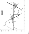
- FIG. 3 shows a profile of the voltages U 1 , U 2 and currents I 1 , I 2 for both winding phases 21, 22 of the two-strand synchronous motor. 2
- an alignment 100 of the rotor 24 of the two-strand synchronous motor 2 takes place under a pole pair of a winding strand 21, 22 of the stator 23, to assume a defined starting position of the rotor 24, which can lead to a rotation of the rotor 2 in a defined predetermined direction of rotation.
- the rotor 24 is energized by a plurality of DC pulses first of both winding strands 21, 22 in a first sub-step 110 and then only the first winding strand 21 in a second sub-step 120. Is a defined position of the rotor 24 taken under the poles of the stator 23, the energization can be omitted, since this defined position can be automatically held by the reluctance.
- the starting 200 of the rotor 24 of the two-strand synchronous motor 2 in the predetermined direction of rotation by substantially simultaneous energization of both winding strands 21, 22 with AC voltage U with full line voltage U N done. Since the first winding strand 21 is designed for the rated operation or the mains voltage U N , the mains voltage U N can be switched through directly by switching the first triac switch 31 to the first winding strand 21, thus dispensing with a frequency converter and the first winding strand 21 can be operated directly on the mains voltage U N. This also applies to the start-up 200 of the rotor 24 for the second winding section 22, which, however, is switched with a slight phase offset. For example, the first winding strand 21 are operated with a phase angle ⁇ of about 60 ° and the second winding strand 22 with a phase angle ⁇ of about 90 °.
- the second winding strand 22 is designed such that the second winding strand 22 is overexcited when supplied with the mains voltage U N.
- the start-up step 200 can only be carried out for a short time, for example 0.5 seconds, in order to avoid thermal overloading of the second winding strand 22. This can be monitored by the temperature sensor 25, see below.
- the first winding strand 21 no temperature monitoring is required, since the first phase winding 21 can only be operated with the mains voltage U N and not over-excited.
- This can be transferred from the start 100 in the rated operation 400.
- a step of determining 500 a load of the rotor 24 of the two-strand synchronous motor 2 in nominal operation may be performed by the induced voltage of the second winding strand 22 in nominal operation during a period during which the second triac Switch 32 locks, is detected.
- the mains voltage U N is not applied to the second winding strand 22 but the induced voltage resulting from the preceding energization, which voltage can be detected by the voltage measuring unit 34 and evaluated by the microcontroller 30 during this period. From this voltage, the load can be determined.
- From the load can be e.g. determine the direction of rotation, so that a successful start 200 detected in the wrong direction, the two-strand synchronous motor 2 can be stopped and restarted. Also can be read from the load, if no rotation of the rotor 24 has occurred, e.g. because the rotor 24 is blocked. Also in this case, a restart 200 of the rotor 24 can be made.
- a start-up 200 or operation 400 opposite to the structurally preferred direction of rotation of the two-strand synchronous motor can take place selectively, e.g. as a cleaning operation of a drain pump of a washing machine.
- a continuous repetitive detection 600 of a temperature of the second winding strand 22 of the rotor 24 of the two-strand synchronous motor 2 can be carried out by means of the temperature sensor 25 in order to monitor the temperature of the second winding strand 22 this second winding strand 22 can be over-excited by design. If it is detected that a predetermined temperature is exceeded by the detected temperature, switching off 700 of the two-strand synchronous motor 2, for example by blocking both triac switches 31, 32 done to terminate the energization of the winding strands 21, 22 and another Avoid heating by energizing.
- a two-phase synchronous drive 1 can be provided, which can be regulated and nevertheless operated directly at the mains voltage U N. Furthermore, this two-strand synchronous drive 1 can be easily operated and, in particular, simply started from standstill.
Landscapes
- Engineering & Computer Science (AREA)
- Power Engineering (AREA)
- Control Of Ac Motors In General (AREA)
- Motor And Converter Starters (AREA)
Claims (3)
- Entraînement synchrone à double brin (1), comportant un moteur synchrone à double brin (2) présentant un premier brin d'enroulement (21) et un second brin d'enroulement (22), un système électronique de commande (3) présentant un premier commutateur (31) destiné à commuter le premier brin d'enroulement (21) et un second commutateur (32) destiné à commuter le second brin d'enroulement (22), une borne de tension de secteur (33) destinée à prélever une tension de secteur (UN), caractérisé en ce que le premier brin d'enroulement (21) par rapport à son enroulement est réalisé de sorte que, lorsque le premier commutateur (31) est activé à pleine tension de secteur (UN), le courant nominal dans le premier brin d'enroulement (21) circule, en ce que le second brin d'enroulement (22) est réalisé par rapport à son enroulement, de sorte que, lorsque le second commutateur (32) est activé à pleine tension de secteur (UN), un couple du second brin d'enroulement (22) supérieur à celui du courant nominal est produit, le premier brin d'enroulement (21) présente un nombre de spires supérieur à celui du second brin d'enroulement (22), un capteur de température (25) destiné à détecter une température du second brin d'enroulement (22) étant prévu, et aucun capteur de température (25) destiné à détecter une température du premier brin d'enroulement (21) n'étant prévu.
- Entraînement synchrone à double brin (1) selon la revendication 1, dans lequel le premier commutateur (31) est un commutateur Triac (31) et/ou dans lequel le second commutateur (32) est un commutateur Triac (32).
- Appareil électrique, de préférence appareil électroménager, de préférence machine à laver, lavante-séchante, cuisinière ou lave-vaisselle, à entraînement synchrone (1) selon l'une des revendications 1 à 2.
Applications Claiming Priority (1)
| Application Number | Priority Date | Filing Date | Title |
|---|---|---|---|
| DE102016118493.4A DE102016118493A1 (de) | 2016-09-29 | 2016-09-29 | Zwei-strängiger Synchronantrieb |
Publications (2)
| Publication Number | Publication Date |
|---|---|
| EP3301807A1 EP3301807A1 (fr) | 2018-04-04 |
| EP3301807B1 true EP3301807B1 (fr) | 2019-11-13 |
Family
ID=59738245
Family Applications (1)
| Application Number | Title | Priority Date | Filing Date |
|---|---|---|---|
| EP17188253.3A Active EP3301807B1 (fr) | 2016-09-29 | 2017-08-29 | Entraînement synchronisé à deux brins |
Country Status (2)
| Country | Link |
|---|---|
| EP (1) | EP3301807B1 (fr) |
| DE (1) | DE102016118493A1 (fr) |
Families Citing this family (1)
| Publication number | Priority date | Publication date | Assignee | Title |
|---|---|---|---|---|
| CN117614354B (zh) * | 2024-01-22 | 2024-03-29 | 四川通安航天科技有限公司 | 一种双绕组电机的检测控制方法 |
Family Cites Families (5)
| Publication number | Priority date | Publication date | Assignee | Title |
|---|---|---|---|---|
| IT1291608B1 (it) | 1997-04-18 | 1999-01-11 | Sisme Immobiliare S P A | Disposizione a motore sincrono monofase a magneti permanenti |
| DE19820929A1 (de) | 1998-05-09 | 1999-11-11 | Ako Werke Gmbh & Co | Vorrichtung zum Steuern eines Einphasen-Synchronmotors |
| DE10045291A1 (de) | 2000-09-13 | 2002-03-21 | Ebm Werke Gmbh & Co Kg | Verfahren und Schaltungsanordnung für den Anlauf eines permanenterregten Elektromotors |
| DE102006058179A1 (de) | 2006-11-30 | 2008-06-05 | Alfred Kärcher Gmbh & Co. Kg | Hochdruckreinigungsgerät und Verfahren zur Änderung von dessen Motorleistung |
| DE102013107819A1 (de) * | 2013-07-22 | 2015-01-22 | Ebm-Papst Mulfingen Gmbh & Co. Kg | "Schaltung zum thermischen Schutz und zur Leistungsregelung von Elektromotoren" |
-
2016
- 2016-09-29 DE DE102016118493.4A patent/DE102016118493A1/de not_active Withdrawn
-
2017
- 2017-08-29 EP EP17188253.3A patent/EP3301807B1/fr active Active
Non-Patent Citations (1)
| Title |
|---|
| None * |
Also Published As
| Publication number | Publication date |
|---|---|
| DE102016118493A1 (de) | 2018-03-29 |
| EP3301807A1 (fr) | 2018-04-04 |
Similar Documents
| Publication | Publication Date | Title |
|---|---|---|
| EP0945973B1 (fr) | Dispositif de commande pour un moteur synchrone monophase | |
| EP1076408B1 (fr) | Procédé de démarrage d'un moteur à courant continu sans balais | |
| EP1284540A2 (fr) | Entraínement de pompe pour lave-vaiselle | |
| EP2918721B1 (fr) | Dispositif de pompage pour un appareil aquifère et appareil aquifère | |
| EP2744095B1 (fr) | Système mécatronique pour appareil électrique | |
| EP3301807B1 (fr) | Entraînement synchronisé à deux brins | |
| EP4372977A1 (fr) | Système d'entraînement | |
| EP0957570B1 (fr) | Dispositif pour commander un moteur synchrone monophasé | |
| EP2442438A2 (fr) | Dispositif de pompe pour un appareil ménager, appareil ménager et procédé de fonctionnement d'un dispositif d'entraînement | |
| DE102019110045A1 (de) | Verfahren zum Betrieb eines Antriebssystems mit einem Einphasen-Synchronmotor | |
| WO2012049042A2 (fr) | Procédé pour commander un processus de freinage d'un moteur d'entraînement de lave-linge, dispositif d'entraînement et lave-linge associés | |
| BE1030973B1 (de) | Antriebssystem | |
| DE102006004313A1 (de) | Verfahren zur Steuerung eines Gleichspannungs-Elektromotors | |
| EP3905512A1 (fr) | Appareil électroménager doté d'un moteur pouvant être connecté à un réseau à tension alternative | |
| BE1031352B1 (de) | Antriebssystem | |
| DE102016118501A1 (de) | Zweisträngiger Einphasen-Synchronantrieb | |
| EP4593281A1 (fr) | Système d'entraînement | |
| WO2014001545A2 (fr) | Procédé pour commander un moteur pas à pas | |
| BE1029011B1 (de) | Verfahren zur thermischen Überwachung eines bürstenlosen Motors | |
| BE1029062B1 (de) | Verfahren zum Ansteuern eines mindestens zweiphasigen bürstenlosen Motors | |
| BE1029031A1 (de) | Verfahren zur thermischen Überwachung eines mindestens zweiphasigen bürstenlosen Motors | |
| EP3337032B1 (fr) | Procédé de fonctionnement d'un moteur à réluctance | |
| EP4184782A1 (fr) | Procédé de fonctionnement d'un système d'entraînement comprenant un moteur synchrone monophasé | |
| DE102009046681A1 (de) | Antriebsmotor zum Antreiben einer Komponente eines Hausgeräts, Antriebseinrichtung und Hausgerät | |
| DE102013213565B4 (de) | Verfahren zum Bestimmen einer Drehrichtung einer Pumpe |
Legal Events
| Date | Code | Title | Description |
|---|---|---|---|
| PUAI | Public reference made under article 153(3) epc to a published international application that has entered the european phase |
Free format text: ORIGINAL CODE: 0009012 |
|
| STAA | Information on the status of an ep patent application or granted ep patent |
Free format text: STATUS: THE APPLICATION HAS BEEN PUBLISHED |
|
| AK | Designated contracting states |
Kind code of ref document: A1 Designated state(s): AL AT BE BG CH CY CZ DE DK EE ES FI FR GB GR HR HU IE IS IT LI LT LU LV MC MK MT NL NO PL PT RO RS SE SI SK SM TR |
|
| AX | Request for extension of the european patent |
Extension state: BA ME |
|
| STAA | Information on the status of an ep patent application or granted ep patent |
Free format text: STATUS: REQUEST FOR EXAMINATION WAS MADE |
|
| 17P | Request for examination filed |
Effective date: 20180810 |
|
| RBV | Designated contracting states (corrected) |
Designated state(s): AL AT BE BG CH CY CZ DE DK EE ES FI FR GB GR HR HU IE IS IT LI LT LU LV MC MK MT NL NO PL PT RO RS SE SI SK SM TR |
|
| RIN1 | Information on inventor provided before grant (corrected) |
Inventor name: RECH, THOMAS |
|
| GRAP | Despatch of communication of intention to grant a patent |
Free format text: ORIGINAL CODE: EPIDOSNIGR1 |
|
| STAA | Information on the status of an ep patent application or granted ep patent |
Free format text: STATUS: GRANT OF PATENT IS INTENDED |
|
| GRAJ | Information related to disapproval of communication of intention to grant by the applicant or resumption of examination proceedings by the epo deleted |
Free format text: ORIGINAL CODE: EPIDOSDIGR1 |
|
| STAA | Information on the status of an ep patent application or granted ep patent |
Free format text: STATUS: REQUEST FOR EXAMINATION WAS MADE |
|
| INTG | Intention to grant announced |
Effective date: 20190521 |
|
| INTC | Intention to grant announced (deleted) | ||
| GRAP | Despatch of communication of intention to grant a patent |
Free format text: ORIGINAL CODE: EPIDOSNIGR1 |
|
| STAA | Information on the status of an ep patent application or granted ep patent |
Free format text: STATUS: GRANT OF PATENT IS INTENDED |
|
| INTG | Intention to grant announced |
Effective date: 20190702 |
|
| GRAS | Grant fee paid |
Free format text: ORIGINAL CODE: EPIDOSNIGR3 |
|
| GRAA | (expected) grant |
Free format text: ORIGINAL CODE: 0009210 |
|
| STAA | Information on the status of an ep patent application or granted ep patent |
Free format text: STATUS: THE PATENT HAS BEEN GRANTED |
|
| AK | Designated contracting states |
Kind code of ref document: B1 Designated state(s): AL AT BE BG CH CY CZ DE DK EE ES FI FR GB GR HR HU IE IS IT LI LT LU LV MC MK MT NL NO PL PT RO RS SE SI SK SM TR |
|
| REG | Reference to a national code |
Ref country code: CH Ref legal event code: EP Ref country code: AT Ref legal event code: REF Ref document number: 1202726 Country of ref document: AT Kind code of ref document: T Effective date: 20191115 |
|
| REG | Reference to a national code |
Ref country code: DE Ref legal event code: R084 Ref document number: 502017002849 Country of ref document: DE |
|
| REG | Reference to a national code |
Ref country code: DE Ref legal event code: R096 Ref document number: 502017002849 Country of ref document: DE |
|
| REG | Reference to a national code |
Ref country code: IE Ref legal event code: FG4D Free format text: LANGUAGE OF EP DOCUMENT: GERMAN |
|
| REG | Reference to a national code |
Ref country code: GB Ref legal event code: 746 Effective date: 20200211 |
|
| REG | Reference to a national code |
Ref country code: NL Ref legal event code: MP Effective date: 20191113 |
|
| REG | Reference to a national code |
Ref country code: LT Ref legal event code: MG4D |
|
| PG25 | Lapsed in a contracting state [announced via postgrant information from national office to epo] |
Ref country code: PT Free format text: LAPSE BECAUSE OF FAILURE TO SUBMIT A TRANSLATION OF THE DESCRIPTION OR TO PAY THE FEE WITHIN THE PRESCRIBED TIME-LIMIT Effective date: 20200313 Ref country code: LT Free format text: LAPSE BECAUSE OF FAILURE TO SUBMIT A TRANSLATION OF THE DESCRIPTION OR TO PAY THE FEE WITHIN THE PRESCRIBED TIME-LIMIT Effective date: 20191113 Ref country code: NL Free format text: LAPSE BECAUSE OF FAILURE TO SUBMIT A TRANSLATION OF THE DESCRIPTION OR TO PAY THE FEE WITHIN THE PRESCRIBED TIME-LIMIT Effective date: 20191113 Ref country code: FI Free format text: LAPSE BECAUSE OF FAILURE TO SUBMIT A TRANSLATION OF THE DESCRIPTION OR TO PAY THE FEE WITHIN THE PRESCRIBED TIME-LIMIT Effective date: 20191113 Ref country code: NO Free format text: LAPSE BECAUSE OF FAILURE TO SUBMIT A TRANSLATION OF THE DESCRIPTION OR TO PAY THE FEE WITHIN THE PRESCRIBED TIME-LIMIT Effective date: 20200213 Ref country code: GR Free format text: LAPSE BECAUSE OF FAILURE TO SUBMIT A TRANSLATION OF THE DESCRIPTION OR TO PAY THE FEE WITHIN THE PRESCRIBED TIME-LIMIT Effective date: 20200214 Ref country code: PL Free format text: LAPSE BECAUSE OF FAILURE TO SUBMIT A TRANSLATION OF THE DESCRIPTION OR TO PAY THE FEE WITHIN THE PRESCRIBED TIME-LIMIT Effective date: 20191113 Ref country code: LV Free format text: LAPSE BECAUSE OF FAILURE TO SUBMIT A TRANSLATION OF THE DESCRIPTION OR TO PAY THE FEE WITHIN THE PRESCRIBED TIME-LIMIT Effective date: 20191113 Ref country code: BG Free format text: LAPSE BECAUSE OF FAILURE TO SUBMIT A TRANSLATION OF THE DESCRIPTION OR TO PAY THE FEE WITHIN THE PRESCRIBED TIME-LIMIT Effective date: 20200213 Ref country code: SE Free format text: LAPSE BECAUSE OF FAILURE TO SUBMIT A TRANSLATION OF THE DESCRIPTION OR TO PAY THE FEE WITHIN THE PRESCRIBED TIME-LIMIT Effective date: 20191113 |
|
| PG25 | Lapsed in a contracting state [announced via postgrant information from national office to epo] |
Ref country code: HR Free format text: LAPSE BECAUSE OF FAILURE TO SUBMIT A TRANSLATION OF THE DESCRIPTION OR TO PAY THE FEE WITHIN THE PRESCRIBED TIME-LIMIT Effective date: 20191113 Ref country code: RS Free format text: LAPSE BECAUSE OF FAILURE TO SUBMIT A TRANSLATION OF THE DESCRIPTION OR TO PAY THE FEE WITHIN THE PRESCRIBED TIME-LIMIT Effective date: 20191113 Ref country code: IS Free format text: LAPSE BECAUSE OF FAILURE TO SUBMIT A TRANSLATION OF THE DESCRIPTION OR TO PAY THE FEE WITHIN THE PRESCRIBED TIME-LIMIT Effective date: 20200313 |
|
| PG25 | Lapsed in a contracting state [announced via postgrant information from national office to epo] |
Ref country code: AL Free format text: LAPSE BECAUSE OF FAILURE TO SUBMIT A TRANSLATION OF THE DESCRIPTION OR TO PAY THE FEE WITHIN THE PRESCRIBED TIME-LIMIT Effective date: 20191113 |
|
| PG25 | Lapsed in a contracting state [announced via postgrant information from national office to epo] |
Ref country code: RO Free format text: LAPSE BECAUSE OF FAILURE TO SUBMIT A TRANSLATION OF THE DESCRIPTION OR TO PAY THE FEE WITHIN THE PRESCRIBED TIME-LIMIT Effective date: 20191113 Ref country code: CZ Free format text: LAPSE BECAUSE OF FAILURE TO SUBMIT A TRANSLATION OF THE DESCRIPTION OR TO PAY THE FEE WITHIN THE PRESCRIBED TIME-LIMIT Effective date: 20191113 Ref country code: DK Free format text: LAPSE BECAUSE OF FAILURE TO SUBMIT A TRANSLATION OF THE DESCRIPTION OR TO PAY THE FEE WITHIN THE PRESCRIBED TIME-LIMIT Effective date: 20191113 Ref country code: ES Free format text: LAPSE BECAUSE OF FAILURE TO SUBMIT A TRANSLATION OF THE DESCRIPTION OR TO PAY THE FEE WITHIN THE PRESCRIBED TIME-LIMIT Effective date: 20191113 Ref country code: EE Free format text: LAPSE BECAUSE OF FAILURE TO SUBMIT A TRANSLATION OF THE DESCRIPTION OR TO PAY THE FEE WITHIN THE PRESCRIBED TIME-LIMIT Effective date: 20191113 |
|
| REG | Reference to a national code |
Ref country code: DE Ref legal event code: R097 Ref document number: 502017002849 Country of ref document: DE |
|
| PG25 | Lapsed in a contracting state [announced via postgrant information from national office to epo] |
Ref country code: SM Free format text: LAPSE BECAUSE OF FAILURE TO SUBMIT A TRANSLATION OF THE DESCRIPTION OR TO PAY THE FEE WITHIN THE PRESCRIBED TIME-LIMIT Effective date: 20191113 Ref country code: SK Free format text: LAPSE BECAUSE OF FAILURE TO SUBMIT A TRANSLATION OF THE DESCRIPTION OR TO PAY THE FEE WITHIN THE PRESCRIBED TIME-LIMIT Effective date: 20191113 |
|
| PLBE | No opposition filed within time limit |
Free format text: ORIGINAL CODE: 0009261 |
|
| STAA | Information on the status of an ep patent application or granted ep patent |
Free format text: STATUS: NO OPPOSITION FILED WITHIN TIME LIMIT |
|
| 26N | No opposition filed |
Effective date: 20200814 |
|
| PG25 | Lapsed in a contracting state [announced via postgrant information from national office to epo] |
Ref country code: SI Free format text: LAPSE BECAUSE OF FAILURE TO SUBMIT A TRANSLATION OF THE DESCRIPTION OR TO PAY THE FEE WITHIN THE PRESCRIBED TIME-LIMIT Effective date: 20191113 |
|
| PG25 | Lapsed in a contracting state [announced via postgrant information from national office to epo] |
Ref country code: IT Free format text: LAPSE BECAUSE OF FAILURE TO SUBMIT A TRANSLATION OF THE DESCRIPTION OR TO PAY THE FEE WITHIN THE PRESCRIBED TIME-LIMIT Effective date: 20191113 |
|
| PG25 | Lapsed in a contracting state [announced via postgrant information from national office to epo] |
Ref country code: MC Free format text: LAPSE BECAUSE OF FAILURE TO SUBMIT A TRANSLATION OF THE DESCRIPTION OR TO PAY THE FEE WITHIN THE PRESCRIBED TIME-LIMIT Effective date: 20191113 |
|
| REG | Reference to a national code |
Ref country code: CH Ref legal event code: PL |
|
| PG25 | Lapsed in a contracting state [announced via postgrant information from national office to epo] |
Ref country code: CH Free format text: LAPSE BECAUSE OF NON-PAYMENT OF DUE FEES Effective date: 20200831 Ref country code: LI Free format text: LAPSE BECAUSE OF NON-PAYMENT OF DUE FEES Effective date: 20200831 Ref country code: LU Free format text: LAPSE BECAUSE OF NON-PAYMENT OF DUE FEES Effective date: 20200829 |
|
| REG | Reference to a national code |
Ref country code: BE Ref legal event code: MM Effective date: 20200831 |
|
| PG25 | Lapsed in a contracting state [announced via postgrant information from national office to epo] |
Ref country code: IE Free format text: LAPSE BECAUSE OF NON-PAYMENT OF DUE FEES Effective date: 20200829 Ref country code: BE Free format text: LAPSE BECAUSE OF NON-PAYMENT OF DUE FEES Effective date: 20200831 |
|
| PG25 | Lapsed in a contracting state [announced via postgrant information from national office to epo] |
Ref country code: TR Free format text: LAPSE BECAUSE OF FAILURE TO SUBMIT A TRANSLATION OF THE DESCRIPTION OR TO PAY THE FEE WITHIN THE PRESCRIBED TIME-LIMIT Effective date: 20191113 Ref country code: MT Free format text: LAPSE BECAUSE OF FAILURE TO SUBMIT A TRANSLATION OF THE DESCRIPTION OR TO PAY THE FEE WITHIN THE PRESCRIBED TIME-LIMIT Effective date: 20191113 Ref country code: CY Free format text: LAPSE BECAUSE OF FAILURE TO SUBMIT A TRANSLATION OF THE DESCRIPTION OR TO PAY THE FEE WITHIN THE PRESCRIBED TIME-LIMIT Effective date: 20191113 |
|
| PG25 | Lapsed in a contracting state [announced via postgrant information from national office to epo] |
Ref country code: MK Free format text: LAPSE BECAUSE OF FAILURE TO SUBMIT A TRANSLATION OF THE DESCRIPTION OR TO PAY THE FEE WITHIN THE PRESCRIBED TIME-LIMIT Effective date: 20191113 |
|
| P01 | Opt-out of the competence of the unified patent court (upc) registered |
Effective date: 20230528 |
|
| REG | Reference to a national code |
Ref country code: AT Ref legal event code: MM01 Ref document number: 1202726 Country of ref document: AT Kind code of ref document: T Effective date: 20220829 |
|
| PG25 | Lapsed in a contracting state [announced via postgrant information from national office to epo] |
Ref country code: AT Free format text: LAPSE BECAUSE OF NON-PAYMENT OF DUE FEES Effective date: 20220829 |
|
| PGFP | Annual fee paid to national office [announced via postgrant information from national office to epo] |
Ref country code: DE Payment date: 20250831 Year of fee payment: 9 |
|
| PGFP | Annual fee paid to national office [announced via postgrant information from national office to epo] |
Ref country code: GB Payment date: 20250826 Year of fee payment: 9 |
|
| PGFP | Annual fee paid to national office [announced via postgrant information from national office to epo] |
Ref country code: FR Payment date: 20250825 Year of fee payment: 9 |