EP2443706B1 - Generator und lasersystem mit gekoppelten subkavitäten - Google Patents
Generator und lasersystem mit gekoppelten subkavitäten Download PDFInfo
- Publication number
- EP2443706B1 EP2443706B1 EP10734262.8A EP10734262A EP2443706B1 EP 2443706 B1 EP2443706 B1 EP 2443706B1 EP 10734262 A EP10734262 A EP 10734262A EP 2443706 B1 EP2443706 B1 EP 2443706B1
- Authority
- EP
- European Patent Office
- Prior art keywords
- sub
- laser
- cavity
- cavities
- laser system
- Prior art date
- Legal status (The legal status is an assumption and is not a legal conclusion. Google has not performed a legal analysis and makes no representation as to the accuracy of the status listed.)
- Active
Links
Images


Classifications
-
- H—ELECTRICITY
- H01—ELECTRIC ELEMENTS
- H01S—DEVICES USING THE PROCESS OF LIGHT AMPLIFICATION BY STIMULATED EMISSION OF RADIATION [LASER] TO AMPLIFY OR GENERATE LIGHT; DEVICES USING STIMULATED EMISSION OF ELECTROMAGNETIC RADIATION IN WAVE RANGES OTHER THAN OPTICAL
- H01S3/00—Lasers, i.e. devices using stimulated emission of electromagnetic radiation in the infrared, visible or ultraviolet wave range
- H01S3/05—Construction or shape of optical resonators; Accommodation of active medium therein; Shape of active medium
- H01S3/08—Construction or shape of optical resonators or components thereof
- H01S3/081—Construction or shape of optical resonators or components thereof comprising three or more reflectors
- H01S3/082—Construction or shape of optical resonators or components thereof comprising three or more reflectors defining a plurality of resonators, e.g. for mode selection or suppression
-
- H—ELECTRICITY
- H01—ELECTRIC ELEMENTS
- H01S—DEVICES USING THE PROCESS OF LIGHT AMPLIFICATION BY STIMULATED EMISSION OF RADIATION [LASER] TO AMPLIFY OR GENERATE LIGHT; DEVICES USING STIMULATED EMISSION OF ELECTROMAGNETIC RADIATION IN WAVE RANGES OTHER THAN OPTICAL
- H01S3/00—Lasers, i.e. devices using stimulated emission of electromagnetic radiation in the infrared, visible or ultraviolet wave range
- H01S3/05—Construction or shape of optical resonators; Accommodation of active medium therein; Shape of active medium
- H01S3/06—Construction or shape of active medium
- H01S3/0627—Construction or shape of active medium the resonator being monolithic, e.g. microlaser
-
- H—ELECTRICITY
- H01—ELECTRIC ELEMENTS
- H01S—DEVICES USING THE PROCESS OF LIGHT AMPLIFICATION BY STIMULATED EMISSION OF RADIATION [LASER] TO AMPLIFY OR GENERATE LIGHT; DEVICES USING STIMULATED EMISSION OF ELECTROMAGNETIC RADIATION IN WAVE RANGES OTHER THAN OPTICAL
- H01S3/00—Lasers, i.e. devices using stimulated emission of electromagnetic radiation in the infrared, visible or ultraviolet wave range
- H01S3/05—Construction or shape of optical resonators; Accommodation of active medium therein; Shape of active medium
- H01S3/08—Construction or shape of optical resonators or components thereof
- H01S3/08013—Resonator comprising a fibre, e.g. for modifying dispersion or repetition rate
-
- H—ELECTRICITY
- H01—ELECTRIC ELEMENTS
- H01S—DEVICES USING THE PROCESS OF LIGHT AMPLIFICATION BY STIMULATED EMISSION OF RADIATION [LASER] TO AMPLIFY OR GENERATE LIGHT; DEVICES USING STIMULATED EMISSION OF ELECTROMAGNETIC RADIATION IN WAVE RANGES OTHER THAN OPTICAL
- H01S3/00—Lasers, i.e. devices using stimulated emission of electromagnetic radiation in the infrared, visible or ultraviolet wave range
- H01S3/10—Controlling the intensity, frequency, phase, polarisation or direction of the emitted radiation, e.g. switching, gating, modulating or demodulating
- H01S3/106—Controlling the intensity, frequency, phase, polarisation or direction of the emitted radiation, e.g. switching, gating, modulating or demodulating by controlling devices placed within the cavity
- H01S3/108—Controlling the intensity, frequency, phase, polarisation or direction of the emitted radiation, e.g. switching, gating, modulating or demodulating by controlling devices placed within the cavity using non-linear optical devices, e.g. exhibiting Brillouin or Raman scattering
-
- H—ELECTRICITY
- H01—ELECTRIC ELEMENTS
- H01S—DEVICES USING THE PROCESS OF LIGHT AMPLIFICATION BY STIMULATED EMISSION OF RADIATION [LASER] TO AMPLIFY OR GENERATE LIGHT; DEVICES USING STIMULATED EMISSION OF ELECTROMAGNETIC RADIATION IN WAVE RANGES OTHER THAN OPTICAL
- H01S3/00—Lasers, i.e. devices using stimulated emission of electromagnetic radiation in the infrared, visible or ultraviolet wave range
- H01S3/10—Controlling the intensity, frequency, phase, polarisation or direction of the emitted radiation, e.g. switching, gating, modulating or demodulating
- H01S3/11—Mode locking; Q-switching; Other giant-pulse techniques, e.g. cavity dumping
- H01S3/1123—Q-switching
- H01S3/113—Q-switching using intracavity saturable absorbers
-
- H—ELECTRICITY
- H01—ELECTRIC ELEMENTS
- H01S—DEVICES USING THE PROCESS OF LIGHT AMPLIFICATION BY STIMULATED EMISSION OF RADIATION [LASER] TO AMPLIFY OR GENERATE LIGHT; DEVICES USING STIMULATED EMISSION OF ELECTROMAGNETIC RADIATION IN WAVE RANGES OTHER THAN OPTICAL
- H01S3/00—Lasers, i.e. devices using stimulated emission of electromagnetic radiation in the infrared, visible or ultraviolet wave range
- H01S3/10—Controlling the intensity, frequency, phase, polarisation or direction of the emitted radiation, e.g. switching, gating, modulating or demodulating
- H01S3/11—Mode locking; Q-switching; Other giant-pulse techniques, e.g. cavity dumping
- H01S3/1123—Q-switching
- H01S3/117—Q-switching using intracavity acousto-optic devices
-
- H—ELECTRICITY
- H01—ELECTRIC ELEMENTS
- H01S—DEVICES USING THE PROCESS OF LIGHT AMPLIFICATION BY STIMULATED EMISSION OF RADIATION [LASER] TO AMPLIFY OR GENERATE LIGHT; DEVICES USING STIMULATED EMISSION OF ELECTROMAGNETIC RADIATION IN WAVE RANGES OTHER THAN OPTICAL
- H01S3/00—Lasers, i.e. devices using stimulated emission of electromagnetic radiation in the infrared, visible or ultraviolet wave range
- H01S3/23—Arrangements of two or more lasers not provided for in groups H01S3/02 - H01S3/22, e.g. tandem arrangements of separate active media
- H01S3/2383—Parallel arrangements
Definitions
- the present invention relates to the field of laser sources producing pulses of sub-nanosecond duration.
- It relates more particularly to a laser system comprising a cavity formed of at least two sub-cavities as well as optical pumping means of a first of these at least two sub-cavities. It also relates to a laser generator comprising at least two of these laser systems.
- the state of the art in this field comprises laser sources capable of producing generally monochromatic or quasi-monochromatic radiation. Such sources use cavities operating in a passive trip mode, called "Q-SWITCH”.
- a passively triggered monolithic microlaser includes a laser cavity formed of a gain medium and a saturable absorber disposed between two dielectric layers.
- a pump beam illuminates the gain medium through a first dielectric layer, which causes an excitation of the ions and energy stored in the gain medium. Since the energy inside the gain medium increases and the intracavity intensity at the wavelength of the microlaser also increases, the absorbent becomes saturated, resulting in rapid extraction of a portion of the microlaser. stored energy in pulse form.
- the absorbent After the emission of the pulse, the absorbent is no longer saturated for a certain period of time, before becoming it again and causing the emission a new impulse.
- the frequency of recurrence of the pulses is thus determined by the physical properties of the saturable absorber and the gain medium.
- a trigger laser and double cavity is proposed in the patent document US 4,982,405 , which describes a laser comprising a cavity formed of two resonant sub-cavities.
- the first sub-cavity includes a gain medium and is illuminated by a pump beam.
- the second sub-cavity includes a non-linear medium and is illuminated by a second incident laser beam. These two sub-cavities are adjacent and are coupled by the constitution of a partially reflecting mirror in common. The length of the optical path of the second sub-cavity is adjusted to influence the Q-factor of the first sub-cavity containing the gain medium.
- Triggered lasers are also known from EP 0 742 613 and of " G-switched microchip laser with 65 ps jitter timing ", B. Hansson and M. Anvidsson, Electronics Letters, Vol 36, No. 13, June 22, 2000 .
- the object of the present invention is to overcome this technical problem, by arranging two of the sub-cavities so as to form a passive sub-cavity incorporating a passive trigger, insufficiently pumped to generate a light pulse, and a sub-cavity active integrating an active trigger coupled to the passive sub-cavity to cause the triggering of the light pulse.
- the approach of the solution consisted of seeking to combine the advantages of passive type triggers (short pulse generation) and active type triggers (low temporal jitter) in order to solve the problem of time jitter of microlasers producing pulses of subnanosecond duration.
- the initially targeted application initially concerned the cellular diagnosis by flow cytometry, for which it is necessary to temporally synchronize a test laser pulse with a cell propagating in front of an analysis window.
- Passive triggers of the saturable absorber type have the particularity of generating short pulses when they are introduced into very short cavities (microlaser cavity with sub-centimeter dimensions). Unfortunately, their trigger time jitter is large. Active triggers are cumbersome and, unlike passive triggers, generate longer pulses but have low temporal jitter.
- One of the aims of the invention is therefore to simultaneously use these two systems while preserving their characteristics and their environment.
- This implementation results in their integration in a very short cavity, which is currently impossible because of their size.
- the use of two coupled cavities solves this problem. Nevertheless, the characteristics of the laser system must be such that the active cavity has the potential to trigger the passive cavity. The passive cavity then forms the short pulse without significant influence of the first cavity after triggering. For this, it is recommended to have a very short passive cavity and a very long active cavity so that at least one longitudinal mode of the active cavity can oscillate within the passive cavity.
- the present invention relates to a laser system comprising a cavity formed of at least two sub-cavities and optical pumping means of a first of the at least two sub-cavities.
- the optical pumping means are arranged so as not to reach the laser emission threshold of the first sub-cavity.
- This first sub-cavity comprises means for generating a short pulse.
- a second sub-cavity comprises external triggering means. These first and second sub-cavities are coupled so that the triggering of this second sub-cavity causes the start of the short pulse generated by this first sub-cavity.
- the first and second sub-cavities act as modules coupled to each other in a predetermined manner to dissociate the formation of a high energy pulse by a microcavity and the amplification of this pulse.
- These two modules being integrated within a single resonator, their cascading favors the generation sub-nanosecond laser pulses and high energy without temporal jitter with respect to an external trigger signal.
- the first sub-cavity is not optically pumped sufficiently to reach on its own the laser emission threshold of the cavity.
- the second sub-cavity comprises, in turn, an external triggering means which, because of the coupling between the two sub-cavities, makes it possible to trigger a short-duration light pulse.
- This both active and passive triggering of the laser cavity makes it possible to reach recurrence frequencies between 0 and 150 kHz and to obtain sub-nanosecond pulse durations without time jitter.
- the first sub-cavity comprises a gain medium, in order to amplify the light emitted by the pumping means of this sub-cavity, without however reaching the laser emission threshold of the cavity.
- the means for generating a short pulse comprise a saturable absorber.
- This type of element is indeed particularly suited to the accumulation of light energy for a given period of time, and then release it after a trigger to generate pulses of short duration.
- the second (active) sub-cavity comprises a gain medium in order to amplify the light signal coming from the first sub-cavity.
- the external triggering means comprise an acousto-optic modulator.
- the two sub-cavities of the system comprise at each of their ends a means of partial reflection of the light.
- a variant Particularly advantageous is to use Bragg mirrors as partial reflection means.
- the coupling of the two sub-cavities is effected by the provision of a partial reflection means common to said two sub-cavities.
- the optical pumping means are arranged to be substantially close to the laser emission threshold of said first sub-cavity without reaching it.
- the temporal jitter is in fact even lower than one is far from the threshold of emission and that one has the capacity to pass largely above this threshold with the action of the second active cavity.
- the external triggering means are able to be controlled by a synchronization signal.
- the laser system comprises frequency conversion means.
- Such a system makes it possible to generate other frequencies than that fixed by the nature of the laser medium.
- the frequency conversion means are in the form of a non-linear optical fiber.
- the second sub-cavity has a greater longitudinal dimension than that of the first sub-cavity, and preferably much larger (for example by a factor of 10), which makes it possible to have at least a longitudinal mode oscillating in the second sub-cavity which is also capable of oscillating in the first sub-cavity.
- the present invention also relates to a laser generator comprising at least two laser systems as described above.
- the second sub-cavities of at least two laser systems have a partial reflection means in common, which allows to couple them.
- the generator may comprise means for synchronizing the pumping means of at least two laser systems.
- a first variant consists of arranging the synchronization means to temporally synchronize the light pulses from the corresponding pumping means, which makes it possible to increase the light power of the generator.
- a second variant consists in arranging the synchronization means to temporally desynchronize the light pulses from the corresponding pumping means, which makes it possible to increase the frequency of recurrence of the generator.
- the second sub-cavities of at least two laser systems have an external triggering means in common.
- a laser system 1 according to a first embodiment of the invention comprises a cavity formed of two sub-cavities 2 and 3 coupled to each other. It may be disposed in this cavity a number of sub-cavities greater than 2 without departing from the scope of this patent.
- the coupling between cavities is of the interferometric type in the sense that, as will be clear from reading the description which follows, the coupling plays on the same wavelength and may give rise to losses related to the superposition in phase or no different components of the laser radiation. Thus, the modification of a parameter of one of the cavities imposes a change in the other cavities.
- the first sub-cavity 2 comprises a gain medium 20 and a passive saturable absorber 21. According to an alternative embodiment, these two elements 20 and 21 can be included in a single component.
- the microchip 20 may be a 1,1% YAG microlaser and the saturable absorbent 21 of CR4 + (absorbent) abs 3 cm -1 .
- This first sub-cavity 2 also comprises two Bragg mirrors 10 and 11, disposed at each end of the sub-cavity.
- the second sub-cavity 3 comprises an external trigger 30 surrounded by two Bragg mirrors 11 and 12.
- the coupling of the two sub-cavities 2 and 3 is effected by the common arrangement of the Bragg mirror 11, the latter being at one end of the first sub-cavity 2 and at the other end of the second sub-cavity 3.
- the Bragg mirrors 10 and 12 - at the other two ends of the two sub-cavities - then constitute the two mirrors surrounding the main cavity.
- the laser system 1 finally comprises an optical pumping means 4 of the first sub-cavity 2. It is disposed vis-à-vis this sub-cavity so as not to reach the laser emission threshold of the cavity, while being substantially close.
- the saturable absorber 21 of the first sub-cavity 2 can store the pumped light energy and release it only under the effect of the external trigger operated by the trigger 30 of the second sub-cavity 3, so as to reach the laser threshold of the cavity.
- the operating frequency of the trigger 30 determines the transmission frequency of the light pulses from the laser system 1.
- the duration of the optical pulse generated is determined by the length of the cavity 1 and the type of saturable absorber positioned at inside.
- the active triggering of the second cavity, by the trigger 30, thus causes the passive triggering, by saturation of the saturable absorber 21, of the first sub-cavity.
- a pump diode 4 having a maximum emission at a wavelength of 808 nanometers and an average power of 3 watts, it may for example be used a mirror 10 whose maximum reflection is at 1064 nanometers and the at 808 nanometers, a mirror 11 with a reflection coefficient 87% and a mirror 12 with a reflection coefficient of 95%.
- a temporal jitter of the order of one hundred picoseconds can then be obtained.
- the second sub-cavity 3 may also include a gain medium in order to amplify the light signal and thus obtain a higher light energy density.
- the second sub-cavity has a longitudinal dimension larger than that of the first sub-cavity, and preferably much larger (for example by a factor greater than or equal to 10), which makes it possible to have at least one oscillating longitudinal mode in the second sub-cavity which is also capable of oscillating in the first sub-cavity.
- a second embodiment of the invention is now described, with the addition of a non-linear medium for the purpose of producing a spectral broadband light emission system, with reference to FIG. figure 2 .
- the laser system here comprises two sub-cavities 3 and 2.
- the coupling between the latter is no longer ensured by the arrangement of a mirror common to the two sub-cavities, but by the arrangement in the same axis of their mirrors 11a and 11b.
- the system also comprises, in the second sub-cavity 3, a non-linear element 31, a polarizer 40, a deflection element 41 (optional, in order to send the beam back to a light power meter) and a half-wave plate 42.
- the non-linear element 31 makes it possible to spread the spectrum of the oscillating central light pulse in the cavity, without affecting the formation of the pulse.
- This element may consist of fibers or crystals. It makes it possible to provide a broad spectrum in the infrared or visible range while maintaining a pulse duration of a few hundred picoseconds.
- This embodiment incorporating a second laser formed by the elements 11b, 30 and 12 improves the tripping of the first cavity by more easily saturating its gain medium with the contribution of external optical energy. This makes it easier to control the temporal jitter of the first cavity.
- the elements 40 and 42 together make a power controller for dosing the amount of energy sent to the cavity 1.
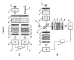
- a laser generator comprises two laser systems 1a and 1b, adjacent to each other.
- the last mirror 12 is common to both laser systems 1a and 1b.
- the gain media 20a and 20b, as well as the saturable absorbers 21a and 21b, have identical physical properties. In another variant embodiment, their physical properties may be different.
- Each of the two laser systems delivers pulses with a certain recurrence period.
- the durations of the pulses, as well as their periods of recurrence and their powers are identical.
- the two output beams 50 and 51 are then superimposed.
- a laser generator comprises two laser systems 1a and 1b, adjacent to each other, and operating in parallel.
- the optical pumping means 4a and 4b, the mirrors 10a, 11a and 10b, 11b, the gain media 20a and 20b and the saturable absorbers 21a and 21b are identical to those of the embodiment illustrated by FIG. figure 3A .
- the two laser systems 1a and 1b have an external trigger 30 and a last mirror 12 in common.
- a synchronization means 5 is also connected to the two pumping means 4a and 4b, in order to synchronize the pump beams that are derived therefrom.
- a non-linear element 31 In the path of the output laser beam from the first laser system 1a is disposed a non-linear element 31 as described in the embodiment illustrated by FIG. figure 2 .
- This element 31 makes it possible to widen the spectrum of the output laser beam, in order to obtain an output beam 52 that is pulsed and has a broad spectral range.
- the output laser beam 53 from the second laser system 1b is not changed.
- Two output beams 52 and 53 are thus obtained, one of which is broad spectrum and the other quasi-monochromatic, these two beams being synchronized with respect to each other, which have advantages for applications for example, for the detection of spectral signatures of particles of the CARS type (coherent anti-Stokes Raman scattering, or in the English language “Coherent Anti-Stokes Raman Scattering").
- a laser generator comprises two laser systems, adjacent to each other, and operating in cascade.
- the constituent elements of the two laser systems used are identical to those described in the previous embodiment with reference to the Figure 4A .
- the two laser systems have an external trigger 30 and a last mirror 12 in common.
- the other elements are located at 90 ° relative to each other, and on the same side of a semi-reflecting plate 45, each at 45 ° thereof.
- a synchronization means 5 is also connected to the two pumping means 4a and 4b.
- the external trigger 30, the nonlinear element 31 and the common mirror 12 are located on the other side of the blade 45, at 45 ° thereof. Finally, a last part, at 90 ° of the elements 30, 31 and 12, and 45 ° of the blade 45, does not include any element.
- various embodiments can be implemented depending on the application envisaged, for example laser sources with a wide spectral range for biophotonic experiments, spectroscopy, material characterization applications in terms of transparency or dispersion, etc.
Landscapes
- Physics & Mathematics (AREA)
- Electromagnetism (AREA)
- Engineering & Computer Science (AREA)
- Plasma & Fusion (AREA)
- Optics & Photonics (AREA)
- Lasers (AREA)
- Laser Surgery Devices (AREA)
Claims (18)
- Lasersystem, umfassend einen Hohlraum (1), der aus mindestens zwei Unterhohlräumen (2, 3) sowie Mitteln (4) zum optischen Pumpen eines ersten (2) von den mindestens zwei Unterhohlräumen (2, 3) gebildet ist, dadurch gekennzeichnet, dass die Mittel (4) zum optischen Pumpen derart angeordnet sind, dass sie die Laseremissionsschwelle des ersten Unterhohlraums (2) nicht erreichen, wobei der erste Unterhohlraum (2) Mittel (21) zur Erzeugung eines kurzen Impulses umfasst, wobei ein zweiter Unterhohlraum (3) Mittel (30) zur aktiven externen Auslösung umfasst, und dadurch, dass der erste und der zweite Unterhohlraum (2, 3) auf interferometrische Weise gekoppelt sind, so dass die aktive externe Auslösung des zweiten Unterhohlraums (3) den Start des kurzen Impulses hervorruft, der vom ersten Unterhohlraum (2) erzeugt wurde.
- Lasersystem nach Anspruch 1, wobei die Mittel (21) zur Erzeugung eines kurzen Impulses einen sättigbaren Absorber (21) umfassen.
- Lasersystem nach einem der Ansprüche 1 bis 3, wobei der zweite Unterhohlraum (3) ein Verstärkungsmedium umfasst.
- Lasersystem nach einem der vorhergehenden Ansprüche, wobei die Mittel (30) zur externen Auslösung einen akusto-optischen Modulator (30) umfassen.
- Lasersystem nach einem der vorhergehenden Ansprüche, wobei die zwei Unterhohlräume (2, 3) an jedem ihrer Enden ein Mittel (10, 11, 12) zur teilweisen Reflexion des Lichts umfassen.
- Lasersystem nach dem vorhergehenden Anspruch, wobei die Mittel (10, 11, 12) zur teilweisen Reflexion Bragg-Spiegel sind.
- Lasersystem nach einem der Ansprüche 6 oder 7, wobei die Kopplung der zwei Unterhohlräume (2, 3) durch die Positionierung eines Mittels (11) zur teilweisen Reflexion erfolgt, das den zwei Unterhohlräumen (2, 3) gemeinsam ist.
- Lasersystem nach einem der vorhergehenden Ansprüche, wobei die Mittel (4) zum optischen Pumpen derart angeordnet sind, dass sie im Wesentlichen nahe der Laseremissionsschwelle des ersten Unterhohlraums (2) sind, ohne sie zu erreichen.
- Lasersystem nach einem der vorhergehenden Ansprüche, wobei die Mittel (30) zur externen Auslösung dazu ausgelegt sind, um durch ein Synchronisierungssignal gesteuert zu werden.
- Lasersystem nach einem der vorhergehenden Ansprüche, umfassend Mittel (31) zur Frequenzkonversion.
- Lasersystem nach dem vorhergehenden Anspruch, wobei die Mittel (31) zur Frequenzkonversion die Form einer nicht linearen optischen Faser (31) aufweisen.
- Lasersystem nach einem der vorhergehenden Ansprüche, wobei der zweite Unterhohlraum (3) eine Längsabmessung aufweist, die größer als diejenige des ersten Unterhohlraums (2) ist.
- Lasergenerator, umfassend mindestens zwei Lasersysteme (1a, 1b) nach einem der vorhergehenden Ansprüche.
- Lasergenerator nach dem vorhergehenden Anspruch, wobei die zweiten Unterhohlräume von mindestens zwei Lasersystemen (1a, 1b) ein Mittel (12) zur gemeinsamen teilweisen Reflexion aufweisen.
- Lasergenerator nach Anspruch 14 oder 15, umfassend ein Mittel (5) zur Synchronisierung der Pumpmittel (4a, 4b) von mindestens zwei Lasersystemen (1a, 1b).
- Lasergenerator nach Anspruch 15, wobei das Synchronisierungsmittel (5) angeordnet ist, um vorübergehend die Lichtimpulse zu synchronisieren, die aus entsprechenden Pumpmitteln (4a, 4b) stammen.
- Lasergenerator nach Anspruch 15, wobei das Synchronisierungsmittel (5) angeordnet ist, um vorübergehend die Lichtimpulse zu desynchronisieren, die aus entsprechenden Pumpmitteln (4a, 4b) stammen.
- Lasergenerator nach einem der Ansprüche 14 bis 18, wobei die zweiten Unterhohlräume von mindestens zwei Lasersystemen (1a, 1b) ein Mittel (30) zur gemeinsamen externen Auslösung aufweisen.
Applications Claiming Priority (2)
| Application Number | Priority Date | Filing Date | Title |
|---|---|---|---|
| FR0902987A FR2947108B1 (fr) | 2009-06-19 | 2009-06-19 | Generateur et systeme laser a sous-cavites couplees |
| PCT/FR2010/051216 WO2010146316A1 (fr) | 2009-06-19 | 2010-06-17 | Générateur et système laser a sous cavités couplées |
Publications (2)
| Publication Number | Publication Date |
|---|---|
| EP2443706A1 EP2443706A1 (de) | 2012-04-25 |
| EP2443706B1 true EP2443706B1 (de) | 2014-12-24 |
Family
ID=41800814
Family Applications (1)
| Application Number | Title | Priority Date | Filing Date |
|---|---|---|---|
| EP10734262.8A Active EP2443706B1 (de) | 2009-06-19 | 2010-06-17 | Generator und lasersystem mit gekoppelten subkavitäten |
Country Status (5)
| Country | Link |
|---|---|
| US (1) | US8867576B2 (de) |
| EP (1) | EP2443706B1 (de) |
| DK (1) | DK2443706T3 (de) |
| FR (1) | FR2947108B1 (de) |
| WO (1) | WO2010146316A1 (de) |
Families Citing this family (2)
| Publication number | Priority date | Publication date | Assignee | Title |
|---|---|---|---|---|
| FR3034578B1 (fr) | 2015-03-30 | 2018-04-27 | Horiba Abx Sas | Procede et dispositif de declenchement de sources lumineuses impulsionnelles |
| WO2021106757A1 (ja) * | 2019-11-28 | 2021-06-03 | ソニー株式会社 | レーザ素子、レーザ素子の製造方法、レーザ装置およびレーザ増幅素子 |
Family Cites Families (8)
| Publication number | Priority date | Publication date | Assignee | Title |
|---|---|---|---|---|
| US4019156A (en) * | 1975-12-02 | 1977-04-19 | The United States Of America As Represented By The United States Energy Research And Development Administration | Active/passive mode-locked laser oscillator |
| US4982405A (en) * | 1989-09-07 | 1991-01-01 | Massachusette Institute Of Technology | Coupled-cavity Q-switched laser |
| JP2895204B2 (ja) * | 1990-10-22 | 1999-05-24 | パイオニア株式会社 | 光波長変換素子及びその製造方法 |
| US5381431A (en) * | 1993-08-13 | 1995-01-10 | Massachusetts Institute Of Technology | Picosecond Q-switched microlasers |
| FR2734092B1 (fr) * | 1995-05-12 | 1997-06-06 | Commissariat Energie Atomique | Microlaser monolithique declenche et materiau non lineaire intracavite |
| FR2734096B1 (fr) * | 1995-05-12 | 1997-06-06 | Commissariat Energie Atomique | Cavite microlaser et microlaser solide impulsionnel a declenchement passif et a commande externe |
| KR0149127B1 (ko) * | 1995-10-31 | 1998-12-01 | 양승택 | 수동과 능동의 혼합형으로 모드로킹 된 레이저 구도 |
| US7649920B2 (en) | 2007-04-03 | 2010-01-19 | Topcon Corporation | Q-switched microlaser apparatus and method for use |
-
2009
- 2009-06-19 FR FR0902987A patent/FR2947108B1/fr active Active
-
2010
- 2010-06-17 WO PCT/FR2010/051216 patent/WO2010146316A1/fr not_active Ceased
- 2010-06-17 DK DK10734262T patent/DK2443706T3/en active
- 2010-06-17 EP EP10734262.8A patent/EP2443706B1/de active Active
- 2010-06-17 US US13/378,774 patent/US8867576B2/en active Active
Also Published As
| Publication number | Publication date |
|---|---|
| EP2443706A1 (de) | 2012-04-25 |
| US8867576B2 (en) | 2014-10-21 |
| WO2010146316A9 (fr) | 2012-03-01 |
| WO2010146316A1 (fr) | 2010-12-23 |
| FR2947108A1 (fr) | 2010-12-24 |
| US20120170606A1 (en) | 2012-07-05 |
| DK2443706T3 (en) | 2015-03-30 |
| FR2947108B1 (fr) | 2011-12-02 |
Similar Documents
| Publication | Publication Date | Title |
|---|---|---|
| EP3738180B1 (de) | Lasersystem und verfahren zur erzeugung von laserpulsen mit sehr hoher wiederholungsrate | |
| EP3488290B1 (de) | System zum erzeugen von kurzen oder ultrakurzen lichtimpulsen | |
| EP3241259B1 (de) | System und verfahren zur erzeugung wellenlängenabstimmbarer, ultrakurzer lichtpulse mit hoher leistungsspektraldichte | |
| EP3365951B1 (de) | Pulslasersystem mit zeitlich veränderlicher wiederholrate und/oder amplitude | |
| EP1125347B1 (de) | Auto-adaptierte filter zur verfeinerung der laseremission | |
| EP2443706B1 (de) | Generator und lasersystem mit gekoppelten subkavitäten | |
| EP4291949A1 (de) | System und verfahren zur erzeugung eines lichtimpulses mit subpikosekundendauer, die eine dauer und/oder eine wiederholungsfrequenz einstellbar ist | |
| CA3026312C (fr) | Module d'affinement spectral, dispositif a raie spectrale affinee et procede afferent | |
| EP4348776B1 (de) | Mamychev-laseroszillator zur erzeugung ultrakurzer impulse und vorrichtung zum starten davon | |
| EP0303667A1 (de) | Phasenzwangsgekoppelter laser | |
| EP3406006B1 (de) | Vorrichtung zur erzeugung eines polychromatischen photonenstrahls mit im wesentlichen konstanter energie | |
| EP2021827A1 (de) | Laserquelle für lidar-anwendung | |
| WO2015079187A1 (fr) | Systeme pour generer des impulsions optiques courtes de duree inferieure a la periode de la porteuse optique utilisant le principe de l'amplification parametrique | |
| EP2443705B1 (de) | System zur ausstrahlung von polychromatischem licht mit gekoppelten subkavitäten | |
| EP3320586B1 (de) | Injizierter laser und verfahren zur erzeugung longitudinaler multimoden-laserpulse | |
| FR3014604A1 (fr) | Amplificateur a fibre optique double passage pour faisceau lumineux polarise | |
| FR3014605A1 (fr) | Amplificateur a fibre optique double passage multi-etage | |
| FR3018144A1 (fr) | Dispositif d'amplification optique hybride |
Legal Events
| Date | Code | Title | Description |
|---|---|---|---|
| PUAI | Public reference made under article 153(3) epc to a published international application that has entered the european phase |
Free format text: ORIGINAL CODE: 0009012 |
|
| 17P | Request for examination filed |
Effective date: 20111213 |
|
| AK | Designated contracting states |
Kind code of ref document: A1 Designated state(s): AL AT BE BG CH CY CZ DE DK EE ES FI FR GB GR HR HU IE IS IT LI LT LU LV MC MK MT NL NO PL PT RO SE SI SK SM TR |
|
| RIN1 | Information on inventor provided before grant (corrected) |
Inventor name: COUDERC, VINCENT Inventor name: LEPROUX, PHILIPPE, PAUL Inventor name: PAGNOUX, DOMINIQUE Inventor name: DOUTRE, FLORENT |
|
| DAX | Request for extension of the european patent (deleted) | ||
| REG | Reference to a national code |
Ref country code: DE Ref legal event code: R079 Ref document number: 602010021256 Country of ref document: DE Free format text: PREVIOUS MAIN CLASS: H01S0003082000 Ipc: H01S0003080000 |
|
| GRAP | Despatch of communication of intention to grant a patent |
Free format text: ORIGINAL CODE: EPIDOSNIGR1 |
|
| RIC1 | Information provided on ipc code assigned before grant |
Ipc: H01S 3/113 20060101ALI20140723BHEP Ipc: H01S 3/08 20060101AFI20140723BHEP Ipc: H01S 3/108 20060101ALI20140723BHEP Ipc: H01S 3/23 20060101ALI20140723BHEP Ipc: H01S 3/117 20060101ALI20140723BHEP Ipc: H01S 3/082 20060101ALI20140723BHEP Ipc: H01S 3/06 20060101ALI20140723BHEP |
|
| INTG | Intention to grant announced |
Effective date: 20140818 |
|
| GRAS | Grant fee paid |
Free format text: ORIGINAL CODE: EPIDOSNIGR3 |
|
| GRAA | (expected) grant |
Free format text: ORIGINAL CODE: 0009210 |
|
| AK | Designated contracting states |
Kind code of ref document: B1 Designated state(s): AL AT BE BG CH CY CZ DE DK EE ES FI FR GB GR HR HU IE IS IT LI LT LU LV MC MK MT NL NO PL PT RO SE SI SK SM TR |
|
| REG | Reference to a national code |
Ref country code: GB Ref legal event code: FG4D Free format text: NOT ENGLISH |
|
| REG | Reference to a national code |
Ref country code: CH Ref legal event code: EP |
|
| REG | Reference to a national code |
Ref country code: IE Ref legal event code: FG4D Free format text: LANGUAGE OF EP DOCUMENT: FRENCH |
|
| REG | Reference to a national code |
Ref country code: AT Ref legal event code: REF Ref document number: 703559 Country of ref document: AT Kind code of ref document: T Effective date: 20150115 |
|
| REG | Reference to a national code |
Ref country code: DE Ref legal event code: R096 Ref document number: 602010021256 Country of ref document: DE Effective date: 20150226 |
|
| REG | Reference to a national code |
Ref country code: DK Ref legal event code: T3 Effective date: 20150326 |
|
| REG | Reference to a national code |
Ref country code: NL Ref legal event code: VDEP Effective date: 20141224 |
|
| PG25 | Lapsed in a contracting state [announced via postgrant information from national office to epo] |
Ref country code: LT Free format text: LAPSE BECAUSE OF FAILURE TO SUBMIT A TRANSLATION OF THE DESCRIPTION OR TO PAY THE FEE WITHIN THE PRESCRIBED TIME-LIMIT Effective date: 20141224 Ref country code: NO Free format text: LAPSE BECAUSE OF FAILURE TO SUBMIT A TRANSLATION OF THE DESCRIPTION OR TO PAY THE FEE WITHIN THE PRESCRIBED TIME-LIMIT Effective date: 20150324 Ref country code: FI Free format text: LAPSE BECAUSE OF FAILURE TO SUBMIT A TRANSLATION OF THE DESCRIPTION OR TO PAY THE FEE WITHIN THE PRESCRIBED TIME-LIMIT Effective date: 20141224 |
|
| REG | Reference to a national code |
Ref country code: LT Ref legal event code: MG4D |
|
| PG25 | Lapsed in a contracting state [announced via postgrant information from national office to epo] |
Ref country code: SE Free format text: LAPSE BECAUSE OF FAILURE TO SUBMIT A TRANSLATION OF THE DESCRIPTION OR TO PAY THE FEE WITHIN THE PRESCRIBED TIME-LIMIT Effective date: 20141224 Ref country code: LV Free format text: LAPSE BECAUSE OF FAILURE TO SUBMIT A TRANSLATION OF THE DESCRIPTION OR TO PAY THE FEE WITHIN THE PRESCRIBED TIME-LIMIT Effective date: 20141224 Ref country code: HR Free format text: LAPSE BECAUSE OF FAILURE TO SUBMIT A TRANSLATION OF THE DESCRIPTION OR TO PAY THE FEE WITHIN THE PRESCRIBED TIME-LIMIT Effective date: 20141224 Ref country code: GR Free format text: LAPSE BECAUSE OF FAILURE TO SUBMIT A TRANSLATION OF THE DESCRIPTION OR TO PAY THE FEE WITHIN THE PRESCRIBED TIME-LIMIT Effective date: 20150325 |
|
| REG | Reference to a national code |
Ref country code: AT Ref legal event code: MK05 Ref document number: 703559 Country of ref document: AT Kind code of ref document: T Effective date: 20141224 |
|
| PG25 | Lapsed in a contracting state [announced via postgrant information from national office to epo] |
Ref country code: NL Free format text: LAPSE BECAUSE OF FAILURE TO SUBMIT A TRANSLATION OF THE DESCRIPTION OR TO PAY THE FEE WITHIN THE PRESCRIBED TIME-LIMIT Effective date: 20141224 |
|
| PG25 | Lapsed in a contracting state [announced via postgrant information from national office to epo] |
Ref country code: EE Free format text: LAPSE BECAUSE OF FAILURE TO SUBMIT A TRANSLATION OF THE DESCRIPTION OR TO PAY THE FEE WITHIN THE PRESCRIBED TIME-LIMIT Effective date: 20141224 Ref country code: SK Free format text: LAPSE BECAUSE OF FAILURE TO SUBMIT A TRANSLATION OF THE DESCRIPTION OR TO PAY THE FEE WITHIN THE PRESCRIBED TIME-LIMIT Effective date: 20141224 Ref country code: RO Free format text: LAPSE BECAUSE OF FAILURE TO SUBMIT A TRANSLATION OF THE DESCRIPTION OR TO PAY THE FEE WITHIN THE PRESCRIBED TIME-LIMIT Effective date: 20141224 Ref country code: CZ Free format text: LAPSE BECAUSE OF FAILURE TO SUBMIT A TRANSLATION OF THE DESCRIPTION OR TO PAY THE FEE WITHIN THE PRESCRIBED TIME-LIMIT Effective date: 20141224 Ref country code: ES Free format text: LAPSE BECAUSE OF FAILURE TO SUBMIT A TRANSLATION OF THE DESCRIPTION OR TO PAY THE FEE WITHIN THE PRESCRIBED TIME-LIMIT Effective date: 20141224 |
|
| PG25 | Lapsed in a contracting state [announced via postgrant information from national office to epo] |
Ref country code: IS Free format text: LAPSE BECAUSE OF FAILURE TO SUBMIT A TRANSLATION OF THE DESCRIPTION OR TO PAY THE FEE WITHIN THE PRESCRIBED TIME-LIMIT Effective date: 20150424 Ref country code: AT Free format text: LAPSE BECAUSE OF FAILURE TO SUBMIT A TRANSLATION OF THE DESCRIPTION OR TO PAY THE FEE WITHIN THE PRESCRIBED TIME-LIMIT Effective date: 20141224 Ref country code: PL Free format text: LAPSE BECAUSE OF FAILURE TO SUBMIT A TRANSLATION OF THE DESCRIPTION OR TO PAY THE FEE WITHIN THE PRESCRIBED TIME-LIMIT Effective date: 20141224 |
|
| REG | Reference to a national code |
Ref country code: DE Ref legal event code: R097 Ref document number: 602010021256 Country of ref document: DE |
|
| PLBE | No opposition filed within time limit |
Free format text: ORIGINAL CODE: 0009261 |
|
| STAA | Information on the status of an ep patent application or granted ep patent |
Free format text: STATUS: NO OPPOSITION FILED WITHIN TIME LIMIT |
|
| 26N | No opposition filed |
Effective date: 20150925 |
|
| PG25 | Lapsed in a contracting state [announced via postgrant information from national office to epo] |
Ref country code: IT Free format text: LAPSE BECAUSE OF FAILURE TO SUBMIT A TRANSLATION OF THE DESCRIPTION OR TO PAY THE FEE WITHIN THE PRESCRIBED TIME-LIMIT Effective date: 20141224 |
|
| PG25 | Lapsed in a contracting state [announced via postgrant information from national office to epo] |
Ref country code: MC Free format text: LAPSE BECAUSE OF FAILURE TO SUBMIT A TRANSLATION OF THE DESCRIPTION OR TO PAY THE FEE WITHIN THE PRESCRIBED TIME-LIMIT Effective date: 20141224 |
|
| REG | Reference to a national code |
Ref country code: CH Ref legal event code: PL |
|
| PG25 | Lapsed in a contracting state [announced via postgrant information from national office to epo] |
Ref country code: SI Free format text: LAPSE BECAUSE OF FAILURE TO SUBMIT A TRANSLATION OF THE DESCRIPTION OR TO PAY THE FEE WITHIN THE PRESCRIBED TIME-LIMIT Effective date: 20141224 Ref country code: LU Free format text: LAPSE BECAUSE OF FAILURE TO SUBMIT A TRANSLATION OF THE DESCRIPTION OR TO PAY THE FEE WITHIN THE PRESCRIBED TIME-LIMIT Effective date: 20150617 |
|
| REG | Reference to a national code |
Ref country code: IE Ref legal event code: MM4A |
|
| PG25 | Lapsed in a contracting state [announced via postgrant information from national office to epo] |
Ref country code: LI Free format text: LAPSE BECAUSE OF NON-PAYMENT OF DUE FEES Effective date: 20150630 Ref country code: IE Free format text: LAPSE BECAUSE OF NON-PAYMENT OF DUE FEES Effective date: 20150617 Ref country code: CH Free format text: LAPSE BECAUSE OF NON-PAYMENT OF DUE FEES Effective date: 20150630 |
|
| REG | Reference to a national code |
Ref country code: FR Ref legal event code: PLFP Year of fee payment: 7 |
|
| PG25 | Lapsed in a contracting state [announced via postgrant information from national office to epo] |
Ref country code: MT Free format text: LAPSE BECAUSE OF FAILURE TO SUBMIT A TRANSLATION OF THE DESCRIPTION OR TO PAY THE FEE WITHIN THE PRESCRIBED TIME-LIMIT Effective date: 20141224 |
|
| REG | Reference to a national code |
Ref country code: FR Ref legal event code: PLFP Year of fee payment: 8 |
|
| PG25 | Lapsed in a contracting state [announced via postgrant information from national office to epo] |
Ref country code: SM Free format text: LAPSE BECAUSE OF FAILURE TO SUBMIT A TRANSLATION OF THE DESCRIPTION OR TO PAY THE FEE WITHIN THE PRESCRIBED TIME-LIMIT Effective date: 20141224 Ref country code: BG Free format text: LAPSE BECAUSE OF FAILURE TO SUBMIT A TRANSLATION OF THE DESCRIPTION OR TO PAY THE FEE WITHIN THE PRESCRIBED TIME-LIMIT Effective date: 20141224 Ref country code: HU Free format text: LAPSE BECAUSE OF FAILURE TO SUBMIT A TRANSLATION OF THE DESCRIPTION OR TO PAY THE FEE WITHIN THE PRESCRIBED TIME-LIMIT; INVALID AB INITIO Effective date: 20100617 |
|
| PG25 | Lapsed in a contracting state [announced via postgrant information from national office to epo] |
Ref country code: CY Free format text: LAPSE BECAUSE OF FAILURE TO SUBMIT A TRANSLATION OF THE DESCRIPTION OR TO PAY THE FEE WITHIN THE PRESCRIBED TIME-LIMIT Effective date: 20141224 |
|
| PG25 | Lapsed in a contracting state [announced via postgrant information from national office to epo] |
Ref country code: BE Free format text: LAPSE BECAUSE OF NON-PAYMENT OF DUE FEES Effective date: 20150630 |
|
| PG25 | Lapsed in a contracting state [announced via postgrant information from national office to epo] |
Ref country code: TR Free format text: LAPSE BECAUSE OF FAILURE TO SUBMIT A TRANSLATION OF THE DESCRIPTION OR TO PAY THE FEE WITHIN THE PRESCRIBED TIME-LIMIT Effective date: 20141224 |
|
| REG | Reference to a national code |
Ref country code: FR Ref legal event code: PLFP Year of fee payment: 9 |
|
| PG25 | Lapsed in a contracting state [announced via postgrant information from national office to epo] |
Ref country code: MK Free format text: LAPSE BECAUSE OF FAILURE TO SUBMIT A TRANSLATION OF THE DESCRIPTION OR TO PAY THE FEE WITHIN THE PRESCRIBED TIME-LIMIT Effective date: 20141224 |
|
| PG25 | Lapsed in a contracting state [announced via postgrant information from national office to epo] |
Ref country code: PT Free format text: LAPSE BECAUSE OF FAILURE TO SUBMIT A TRANSLATION OF THE DESCRIPTION OR TO PAY THE FEE WITHIN THE PRESCRIBED TIME-LIMIT Effective date: 20141224 |
|
| PG25 | Lapsed in a contracting state [announced via postgrant information from national office to epo] |
Ref country code: AL Free format text: LAPSE BECAUSE OF FAILURE TO SUBMIT A TRANSLATION OF THE DESCRIPTION OR TO PAY THE FEE WITHIN THE PRESCRIBED TIME-LIMIT Effective date: 20141224 |
|
| PGFP | Annual fee paid to national office [announced via postgrant information from national office to epo] |
Ref country code: GB Payment date: 20250626 Year of fee payment: 16 Ref country code: DK Payment date: 20250627 Year of fee payment: 16 |
|
| PGFP | Annual fee paid to national office [announced via postgrant information from national office to epo] |
Ref country code: FR Payment date: 20250626 Year of fee payment: 16 |
|
| PGFP | Annual fee paid to national office [announced via postgrant information from national office to epo] |
Ref country code: DE Payment date: 20250725 Year of fee payment: 16 |