EP3241259B1 - System und verfahren zur erzeugung wellenlängenabstimmbarer, ultrakurzer lichtpulse mit hoher leistungsspektraldichte - Google Patents
System und verfahren zur erzeugung wellenlängenabstimmbarer, ultrakurzer lichtpulse mit hoher leistungsspektraldichte Download PDFInfo
- Publication number
- EP3241259B1 EP3241259B1 EP15823717.2A EP15823717A EP3241259B1 EP 3241259 B1 EP3241259 B1 EP 3241259B1 EP 15823717 A EP15823717 A EP 15823717A EP 3241259 B1 EP3241259 B1 EP 3241259B1
- Authority
- EP
- European Patent Office
- Prior art keywords
- spectral
- wavelength
- filter
- optical
- tunable
- Prior art date
- Legal status (The legal status is an assumption and is not a legal conclusion. Google has not performed a legal analysis and makes no representation as to the accuracy of the status listed.)
- Active
Links
Images


Classifications
-
- H—ELECTRICITY
- H01—ELECTRIC ELEMENTS
- H01S—DEVICES USING THE PROCESS OF LIGHT AMPLIFICATION BY STIMULATED EMISSION OF RADIATION [LASER] TO AMPLIFY OR GENERATE LIGHT; DEVICES USING STIMULATED EMISSION OF ELECTROMAGNETIC RADIATION IN WAVE RANGES OTHER THAN OPTICAL
- H01S3/00—Lasers, i.e. devices using stimulated emission of electromagnetic radiation in the infrared, visible or ultraviolet wave range
- H01S3/005—Optical devices external to the laser cavity, specially adapted for lasers, e.g. for homogenisation of the beam or for manipulating laser pulses, e.g. pulse shaping
- H01S3/0078—Frequency filtering
-
- G—PHYSICS
- G02—OPTICS
- G02B—OPTICAL ELEMENTS, SYSTEMS OR APPARATUS
- G02B26/00—Optical devices or arrangements for the control of light using movable or deformable optical elements
- G02B26/001—Optical devices or arrangements for the control of light using movable or deformable optical elements based on interference in an adjustable optical cavity
-
- G—PHYSICS
- G02—OPTICS
- G02F—OPTICAL DEVICES OR ARRANGEMENTS FOR THE CONTROL OF LIGHT BY MODIFICATION OF THE OPTICAL PROPERTIES OF THE MEDIA OF THE ELEMENTS INVOLVED THEREIN; NON-LINEAR OPTICS; FREQUENCY-CHANGING OF LIGHT; OPTICAL LOGIC ELEMENTS; OPTICAL ANALOGUE/DIGITAL CONVERTERS
- G02F1/00—Devices or arrangements for the control of the intensity, colour, phase, polarisation or direction of light arriving from an independent light source, e.g. switching, gating or modulating; Non-linear optics
- G02F1/01—Devices or arrangements for the control of the intensity, colour, phase, polarisation or direction of light arriving from an independent light source, e.g. switching, gating or modulating; Non-linear optics for the control of the intensity, phase, polarisation or colour
- G02F1/11—Devices or arrangements for the control of the intensity, colour, phase, polarisation or direction of light arriving from an independent light source, e.g. switching, gating or modulating; Non-linear optics for the control of the intensity, phase, polarisation or colour based on acousto-optical elements, e.g. using variable diffraction by sound or like mechanical waves
-
- G—PHYSICS
- G02—OPTICS
- G02F—OPTICAL DEVICES OR ARRANGEMENTS FOR THE CONTROL OF LIGHT BY MODIFICATION OF THE OPTICAL PROPERTIES OF THE MEDIA OF THE ELEMENTS INVOLVED THEREIN; NON-LINEAR OPTICS; FREQUENCY-CHANGING OF LIGHT; OPTICAL LOGIC ELEMENTS; OPTICAL ANALOGUE/DIGITAL CONVERTERS
- G02F1/00—Devices or arrangements for the control of the intensity, colour, phase, polarisation or direction of light arriving from an independent light source, e.g. switching, gating or modulating; Non-linear optics
- G02F1/35—Non-linear optics
- G02F1/39—Non-linear optics for parametric generation or amplification of light, infrared or ultraviolet waves
-
- H—ELECTRICITY
- H01—ELECTRIC ELEMENTS
- H01S—DEVICES USING THE PROCESS OF LIGHT AMPLIFICATION BY STIMULATED EMISSION OF RADIATION [LASER] TO AMPLIFY OR GENERATE LIGHT; DEVICES USING STIMULATED EMISSION OF ELECTROMAGNETIC RADIATION IN WAVE RANGES OTHER THAN OPTICAL
- H01S3/00—Lasers, i.e. devices using stimulated emission of electromagnetic radiation in the infrared, visible or ultraviolet wave range
- H01S3/005—Optical devices external to the laser cavity, specially adapted for lasers, e.g. for homogenisation of the beam or for manipulating laser pulses, e.g. pulse shaping
- H01S3/0057—Temporal shaping, e.g. pulse compression, frequency chirping
-
- H—ELECTRICITY
- H01—ELECTRIC ELEMENTS
- H01S—DEVICES USING THE PROCESS OF LIGHT AMPLIFICATION BY STIMULATED EMISSION OF RADIATION [LASER] TO AMPLIFY OR GENERATE LIGHT; DEVICES USING STIMULATED EMISSION OF ELECTROMAGNETIC RADIATION IN WAVE RANGES OTHER THAN OPTICAL
- H01S3/00—Lasers, i.e. devices using stimulated emission of electromagnetic radiation in the infrared, visible or ultraviolet wave range
- H01S3/005—Optical devices external to the laser cavity, specially adapted for lasers, e.g. for homogenisation of the beam or for manipulating laser pulses, e.g. pulse shaping
- H01S3/0092—Nonlinear frequency conversion, e.g. second harmonic generation [SHG] or sum- or difference-frequency generation outside the laser cavity
-
- H—ELECTRICITY
- H01—ELECTRIC ELEMENTS
- H01S—DEVICES USING THE PROCESS OF LIGHT AMPLIFICATION BY STIMULATED EMISSION OF RADIATION [LASER] TO AMPLIFY OR GENERATE LIGHT; DEVICES USING STIMULATED EMISSION OF ELECTROMAGNETIC RADIATION IN WAVE RANGES OTHER THAN OPTICAL
- H01S3/00—Lasers, i.e. devices using stimulated emission of electromagnetic radiation in the infrared, visible or ultraviolet wave range
- H01S3/05—Construction or shape of optical resonators; Accommodation of active medium therein; Shape of active medium
- H01S3/06—Construction or shape of active medium
- H01S3/063—Waveguide lasers, i.e. whereby the dimensions of the waveguide are of the order of the light wavelength
- H01S3/067—Fibre lasers
- H01S3/06754—Fibre amplifiers
-
- G—PHYSICS
- G02—OPTICS
- G02F—OPTICAL DEVICES OR ARRANGEMENTS FOR THE CONTROL OF LIGHT BY MODIFICATION OF THE OPTICAL PROPERTIES OF THE MEDIA OF THE ELEMENTS INVOLVED THEREIN; NON-LINEAR OPTICS; FREQUENCY-CHANGING OF LIGHT; OPTICAL LOGIC ELEMENTS; OPTICAL ANALOGUE/DIGITAL CONVERTERS
- G02F1/00—Devices or arrangements for the control of the intensity, colour, phase, polarisation or direction of light arriving from an independent light source, e.g. switching, gating or modulating; Non-linear optics
- G02F1/35—Non-linear optics
- G02F1/3528—Non-linear optics for producing a supercontinuum
-
- G—PHYSICS
- G02—OPTICS
- G02F—OPTICAL DEVICES OR ARRANGEMENTS FOR THE CONTROL OF LIGHT BY MODIFICATION OF THE OPTICAL PROPERTIES OF THE MEDIA OF THE ELEMENTS INVOLVED THEREIN; NON-LINEAR OPTICS; FREQUENCY-CHANGING OF LIGHT; OPTICAL LOGIC ELEMENTS; OPTICAL ANALOGUE/DIGITAL CONVERTERS
- G02F2201/00—Constructional arrangements not provided for in groups G02F1/00 - G02F7/00
- G02F2201/34—Constructional arrangements not provided for in groups G02F1/00 - G02F7/00 reflector
-
- H—ELECTRICITY
- H01—ELECTRIC ELEMENTS
- H01S—DEVICES USING THE PROCESS OF LIGHT AMPLIFICATION BY STIMULATED EMISSION OF RADIATION [LASER] TO AMPLIFY OR GENERATE LIGHT; DEVICES USING STIMULATED EMISSION OF ELECTROMAGNETIC RADIATION IN WAVE RANGES OTHER THAN OPTICAL
- H01S2301/00—Functional characteristics
- H01S2301/08—Generation of pulses with special temporal shape or frequency spectrum
-
- H—ELECTRICITY
- H01—ELECTRIC ELEMENTS
- H01S—DEVICES USING THE PROCESS OF LIGHT AMPLIFICATION BY STIMULATED EMISSION OF RADIATION [LASER] TO AMPLIFY OR GENERATE LIGHT; DEVICES USING STIMULATED EMISSION OF ELECTROMAGNETIC RADIATION IN WAVE RANGES OTHER THAN OPTICAL
- H01S3/00—Lasers, i.e. devices using stimulated emission of electromagnetic radiation in the infrared, visible or ultraviolet wave range
- H01S3/05—Construction or shape of optical resonators; Accommodation of active medium therein; Shape of active medium
- H01S3/06—Construction or shape of active medium
- H01S3/063—Waveguide lasers, i.e. whereby the dimensions of the waveguide are of the order of the light wavelength
- H01S3/067—Fibre lasers
- H01S3/06708—Constructional details of the fibre, e.g. compositions, cross-section, shape or tapering
- H01S3/06725—Fibre characterized by a specific dispersion, e.g. for pulse shaping in soliton lasers or for dispersion compensating [DCF]
-
- H—ELECTRICITY
- H01—ELECTRIC ELEMENTS
- H01S—DEVICES USING THE PROCESS OF LIGHT AMPLIFICATION BY STIMULATED EMISSION OF RADIATION [LASER] TO AMPLIFY OR GENERATE LIGHT; DEVICES USING STIMULATED EMISSION OF ELECTROMAGNETIC RADIATION IN WAVE RANGES OTHER THAN OPTICAL
- H01S3/00—Lasers, i.e. devices using stimulated emission of electromagnetic radiation in the infrared, visible or ultraviolet wave range
- H01S3/05—Construction or shape of optical resonators; Accommodation of active medium therein; Shape of active medium
- H01S3/06—Construction or shape of active medium
- H01S3/063—Waveguide lasers, i.e. whereby the dimensions of the waveguide are of the order of the light wavelength
- H01S3/067—Fibre lasers
- H01S3/06754—Fibre amplifiers
- H01S3/06758—Tandem amplifiers
-
- H—ELECTRICITY
- H01—ELECTRIC ELEMENTS
- H01S—DEVICES USING THE PROCESS OF LIGHT AMPLIFICATION BY STIMULATED EMISSION OF RADIATION [LASER] TO AMPLIFY OR GENERATE LIGHT; DEVICES USING STIMULATED EMISSION OF ELECTROMAGNETIC RADIATION IN WAVE RANGES OTHER THAN OPTICAL
- H01S3/00—Lasers, i.e. devices using stimulated emission of electromagnetic radiation in the infrared, visible or ultraviolet wave range
- H01S3/05—Construction or shape of optical resonators; Accommodation of active medium therein; Shape of active medium
- H01S3/06—Construction or shape of active medium
- H01S3/063—Waveguide lasers, i.e. whereby the dimensions of the waveguide are of the order of the light wavelength
- H01S3/067—Fibre lasers
- H01S3/06791—Fibre ring lasers
-
- H—ELECTRICITY
- H01—ELECTRIC ELEMENTS
- H01S—DEVICES USING THE PROCESS OF LIGHT AMPLIFICATION BY STIMULATED EMISSION OF RADIATION [LASER] TO AMPLIFY OR GENERATE LIGHT; DEVICES USING STIMULATED EMISSION OF ELECTROMAGNETIC RADIATION IN WAVE RANGES OTHER THAN OPTICAL
- H01S3/00—Lasers, i.e. devices using stimulated emission of electromagnetic radiation in the infrared, visible or ultraviolet wave range
- H01S3/05—Construction or shape of optical resonators; Accommodation of active medium therein; Shape of active medium
- H01S3/08—Construction or shape of optical resonators or components thereof
- H01S3/08018—Mode suppression
- H01S3/08022—Longitudinal modes
- H01S3/08027—Longitudinal modes by a filter, e.g. a Fabry-Perot filter is used for wavelength setting
-
- H—ELECTRICITY
- H01—ELECTRIC ELEMENTS
- H01S—DEVICES USING THE PROCESS OF LIGHT AMPLIFICATION BY STIMULATED EMISSION OF RADIATION [LASER] TO AMPLIFY OR GENERATE LIGHT; DEVICES USING STIMULATED EMISSION OF ELECTROMAGNETIC RADIATION IN WAVE RANGES OTHER THAN OPTICAL
- H01S3/00—Lasers, i.e. devices using stimulated emission of electromagnetic radiation in the infrared, visible or ultraviolet wave range
- H01S3/10—Controlling the intensity, frequency, phase, polarisation or direction of the emitted radiation, e.g. switching, gating, modulating or demodulating
- H01S3/11—Mode locking; Q-switching; Other giant-pulse techniques, e.g. cavity dumping
- H01S3/1106—Mode locking
- H01S3/1112—Passive mode locking
-
- H—ELECTRICITY
- H01—ELECTRIC ELEMENTS
- H01S—DEVICES USING THE PROCESS OF LIGHT AMPLIFICATION BY STIMULATED EMISSION OF RADIATION [LASER] TO AMPLIFY OR GENERATE LIGHT; DEVICES USING STIMULATED EMISSION OF ELECTROMAGNETIC RADIATION IN WAVE RANGES OTHER THAN OPTICAL
- H01S3/00—Lasers, i.e. devices using stimulated emission of electromagnetic radiation in the infrared, visible or ultraviolet wave range
- H01S3/14—Lasers, i.e. devices using stimulated emission of electromagnetic radiation in the infrared, visible or ultraviolet wave range characterised by the material used as the active medium
- H01S3/16—Solid materials
- H01S3/1601—Solid materials characterised by an active (lasing) ion
- H01S3/1603—Solid materials characterised by an active (lasing) ion rare earth
- H01S3/1618—Solid materials characterised by an active (lasing) ion rare earth ytterbium
Definitions
- the present invention relates generally to lasers. More specifically, the invention relates to a system according to claim 1 and a method according to claim 11 for generating light pulses of picosecond (ps) or sub-picosecond (sub-ps) duration tunable in wavelength.
- ps picosecond
- sub-ps sub-picosecond
- the invention relates to a system and method for generating continuously tunable ps or sub-ps pulses in the visible, near infrared and / or mid-infrared wavelength range.
- ultra-short pulse is understood to mean a pulse of duration of the order of a picosecond, between 0.1 ps and approximately 200 ps.
- short pulse is understood to mean a pulse with a duration of the order of one nanosecond or sub-nanosecond, between approximately 200 ps and 100 ns.
- the spectral range of electromagnetic radiation extends in the visible from 400 to 800 nm, the ultraviolet from 300 to 400 nm, the near infrared from 800 nm to 1.5 microns, l 'mid infrared 1.5 to 10 microns and far infrared 10 to 20 microns.
- the operating range of a laser source is defined by a set of specific parameters including in particular the range of accessible wavelength, the time regime and the level of energy and / or power delivered.
- the wavelength range of a laser can be in the ultra-violet, visible, or infrared.
- the temporal regime of a laser may be continuous or pulsed, the pulses may be of nanosecond, picosecond or femtosecond duration.
- the energy and power delivered by a laser can also vary by several orders of magnitude depending on the type of laser.
- each laser source being dedicated to a specific application.
- a dye laser emitting at a wavelength in the red ( ⁇ about 800 nm) in continuous mode is used.
- a neodymium-YAG (Nd-YAG) laser operates in pulsed or continuous mode in the near infrared ( ⁇ 1 ⁇ m).
- a frequency doubled Nd-YAG laser in a KTP crystal operates in pulsed or continuous mode for emission at wavelength in the green (0.5 ⁇ m) and an erbium-YAG (Er-YAG) laser for infrared emission at 3 ⁇ m.
- the range of treatments is generally limited, in particular by the reduced choice in the accessible wavelengths.
- pulses of shorter and shorter duration More precisely, it is desirable to switch from the regime of nanosecond or sub-nanosecond pulses, that is to say of at least several hundred picoseconds, to a regime of picosecond pulses.
- wavelength tunable dye lasers that generate a laser beam with a power of 1 mW to 10W.
- the wavelength tunability of a dye laser relies on the use of different dyes in the liquid phase.
- One drawback is that each dye has a limited shelf life.
- dye lasers impose severe maintenance constraints. This path has long been abandoned and the only dye lasers still on the market have a very small wavelength range, most of the time mono-color.
- Laser systems are also known based on the combination of a near infrared laser source and a non-linear optical crystal to produce, by second harmonic generation, visible radiation tunable over a range of 40 nm in the blue (between 450 and 490 nm) and over a range of 60 nm in the green (between 500 and 560 nm), with pulse durations from 0.1 ps to 100 ns.
- Other light sources are based on a solid non-linear optical component placed in an optical cavity.
- phase tuning conditions from a pump wave, an OPO generates a signal wave and a complementary wave (idler), the sum of the optical frequencies of the signal wave and the complementary wave being equal to the optical frequency of the pump wave.
- the wavelength tunability of an OPO is achieved by changing the orientation and / or temperature of the non-linear optical component. Nevertheless, the OPO sources did not give rise to any industrial development.
- ROYON ROMAIN ET AL "MW peak power infrared source for tunable visible light generation by Four-Wave Mixing", 2014 CONFERENCE ON LASERS AND ELECTRO-OPTICS (CLEO) - LASER SCIENCE TO PHOTONIC APPLICATIONS, THE OPTICAL SOCIETY, June 8, 2014, pages 1-2 , describes a system for generating ultrashort light pulses tunable in wavelength in a spectral range between ultraviolet and infrared, said system comprising an injection module comprising a supercontinuum light source and a spectral filter tunable in wavelength ("Acousto-Optic Tunable Filter” AOTF) arranged on an optical path downstream of the supercontinuum source, two optical fiber amplifiers being arranged in series at the output of the injection module.
- AOTF spectral filter tunable in wavelength
- the system for generating light pulses prefferably, it is desirable for the system for generating light pulses to be fiber-bundled at the output.
- One of the aims of the invention is to propose a system for generating ultrashort light pulses which can be continuously tuned in wavelength over a wide spectral range.
- the object of the present invention is to remedy the drawbacks of the prior systems and relates more particularly to a system for generating ultrashort light pulses tunable in wavelength in a spectral range comprised between the ultraviolet and the infrared.
- the system comprises an injection module comprising a light source and a spectral filter tunable in wavelength, the light source being adapted to generate short light pulses, with a duration between several hundred picoseconds and a hundred nanoseconds, said brief light pulses extending over an emission spectral band in the near infrared domain, the emission spectral band having a spectral width of several tens of nanometers to several hundreds of nanometers, the spectral filter having at least one spectral bandwidth defined by a spectral width comprised between 10 ⁇ m and 10 nm, preferably from 250 ⁇ m to 1 nm, and a central wavelength, said spectral bandwidth being tunable in a spectral range [Lambda1; Lambda2] included within the spectral emission band of the source, the spectral filter being adapted to spectrally filter and to temporally shape said short light pulses, so that the injection module generates pulses ultra-short light, of duration of the order
- the invention makes it possible to generate pulses that are both ultrashort (from 1 ps to about 20 ps), spectrally filtered with a spectral width of between a few hundred pm and a few nm, and tunable in wavelength over a wide spectral range, for example over a spectral range of at least 50nm to 300 nm wide, for example in the near infrared domain, the central wavelength being about 1 micron.
- the injection module is tunable in wavelength over the spectral range [Lambda1; Lambda2] filter while generating ultrashort pulses of narrow spectral width.
- This injection module makes it possible to inject pulses into different optical amplifiers, and thus obtain ultra-short amplified pulses tunable in wavelength over a wide spectral range, each pulse having a small spectral width (of the order of nanometer). These amplified pulses thus have a high power spectral density.
- the power spectral density is defined here as the ratio between the power of a pulse and the spectral width of this pulse.
- the pulse generation system does not use a pulse compressor, but simply a broadband spectral source combined with a filter having a wavelength tunable bandwidth and an optical amplifier.
- the wavelength tuning of the amplified pulses is very easy to control by the wavelength tuning of the filter.
- the light source comprises a supercontinuum source and the spectral filter is placed on an optical path downstream from the supercontinuum source.
- the light source comprises an amplifying nonlinear loop mirror, the amplifying nonlinear loop mirror comprising another optical amplifier disposed on the optical path of the nonlinear loop mirror and the spectral filter being disposed on the optical path of the nonlinear loop mirror.
- the amplifying nonlinear loop mirror is 8-shaped and comprises a first bidirectional amplifying nonlinear loop and a second unidirectional nonlinear loop, the spectral filter being arranged in the first non-linear loop. linear.
- the spectral filter comprises a prism-based filter, a diffraction grating-based filter, an interference filter, a birefringent filter, a Bragg mirror diffractive filter, a resonant mirror diffractive filter, an acousto filter. -optical or acousto-optical thin film filter.
- the spectral filter is an interference filter or an acousto-optical filter configured to simultaneously filter a plurality of spectral passbands spectrally spaced from one another, each spectral passband being defined by a central wavelength and a spectral width comprised between 10 ⁇ m and 10 nm, and each central wavelength of the spectral filter being tunable in a spectral range comprised within the spectral emission band of the light source.
- the spectral filter has a spectral width of less than 1 nm.
- said at least one optical amplifier comprises a plurality of optical amplifiers arranged in a star around the injection module.
- said at least one optical amplifier comprises an optical fiber preamplifier and a power optical fiber amplifier arranged in series.
- the light source, the spectral filter and / or the at least one optical amplifier comprise optical fiber components.
- said at least one optical amplifier comprises a rare earth doped optical fiber.
- the system for generating ultrashort light pulses further comprises a dispersive optical component with negative dispersion disposed at the output of the at least one optical amplifier, the dispersive optical component being adapted to simultaneously receive a pulse. pump and an ultrashort amplified pulse and for generating, by non-linear optical effect of four-wave mixing, a first optical signal and a second optical signal, the first or the second optical signal comprising an output light pulse of duration of the picosecond to hundred picoseconds at a predetermined wavelength in the ultraviolet, visible or infrared range and having a spectral width less than 10 nm, the predetermined wavelength of the output light pulse being tunable in function of the central wavelength of the spectral filter.
- the dispersive optical component comprises a section of photonic optical fiber.
- the invention will find a particularly advantageous application in systems for generating light pulses for application to imaging in bio-imaging and / or in medicine.
- the invention advantageously makes it possible to provide a system for generating ultrashort light pulses tunable in wavelength over a wide spectral range.
- the laser system makes it possible to generate pulses of continuously tunable wavelength in the visible range from 550 nm to 750 nm or 850 nm and / or in the infrared range from 1.3 to 3 microns. .
- the figure 1 schematically represents the general architecture of a system for generating ultrashort light pulses tunable in wavelength. This system is based on the combination of different modules.
- the system for generating ultrashort light pulses tunable in wavelength comprises an injection module 10, a preamplification module 20 and a power amplification module 30.
- the injection module 10, the preamplification module 20 and the power amplification module 30 are arranged in series.
- the preamplification module 20 comprises for example a first optical preamplifier 21 arranged in series with a second optical preamplifier 22, and separated by a spectral filter 28 preferably bandpass.
- the injection module 10 generates ultrashort light pulses 110 with a duration of the order of a picosecond, spectrally filtered over a narrow pass band of between a few hundred picometers and a few nanometers and tunable in wavelength.
- ultrashort light pulses 110 can then be amplified, to form amplified light pulses 120, 130 tunable in wavelength and of high power spectral density.
- the preamplifier module 20 receives the ultrashort light pulses 110.
- the first optical preamplifier 21 generates preamplified light pulses 121.
- the optical component 28 receives the preamplified light pulses 121 and generates filtered light pulses 128.
- the optical component 28 receives the preamplified light pulses 121 and generates filtered light pulses 128.
- the optical component 28 receives the preamplified light pulses 121.
- second Optical preamplifier 22 receives light pulses 128 and generates pre-amplified light pulses 120.
- the optical power amplifier 30 receives the pre-amplified light pulses 120 and generates amplified light pulses 130. These amplified light pulses 130 are ultrashort, of duration between 0.1 and 30 picoseconds, spectrally filtered over a narrow bandwidth (between 250 ⁇ m and 1.5 nm) and tunable in wavelength according to the wavelength of the injection module 10.
- the amplified light pulses 120, 130 can also be frequency converted so as to generate wavelength tunable light pulses 140, 141 in wavelength domains other than the spectral domain of the injection module.
- the injection module 10 is based on the combination of a light source of the supercontinuum type 9 and a tunable spectral filter 8.
- a supercontinuum source 9 generally comprises a laser source 91 and a dispersive optical component 92, having an anomalous or preferably normal dispersion.
- the laser source 91 emits pulsed radiation, the source pulses having a duration of 800 ps, at a single determined wavelength, for example of 1064 nm, with a spectral width of 0.06 nm.
- a dispersive optical component 92 is used, for example with an optical fiber, and more particularly based on a photonic optical fiber or a microstructured fiber.
- the dispersive optical component 92 spectrally broadens the laser radiation to form supercontinuum-type radiation (SC) extending continuously over a wide spectral band.
- SC supercontinuum-type radiation
- the processes at the origin of the formation of supercontinuum radiation in a photonic or microstructured fiber are in particular phase self-modulation, the Raman effect and / or else four-wave mixing. These physical processes are complex and vary with fiber length, pump pulse duration, and pump wavelength from a wavelength where dispersion is zero, also called zero dispersion.
- the choice of these parameters and of the dispersive optical component 92 determines the spectral width and the spectral shape of the supercontinuum radiation.
- a microstructured fiber 92 is chosen having a zero dispersion wavelength less than 1064 nm (eg 1060 nm) which is optically pumped by a pump diode having a pump wavelength of 1064 nm.
- the zero dispersion wavelength of the microstructured fiber 92 is 1300 nm and the pump wavelength is 1550 nm.
- a dispersive optical component 92 is used.
- the fiber intrinsically produces linearly chirped light pulses 100.
- chirped pulses means time-stretched light pulses
- linearly chirped pulses means pulses having an instantaneous frequency which varies linearly as a function of time.
- the operation of the supercontinuum source 9 in pulsed mode is obtained by controlling a pump of the laser 91.
- the supercontinuum source 9 thus delivers short pulses 100, having a duration of between 0.1 ps and 100 ps, low in energy, having an energy per pulse of the order of 10 nJ to 1 microjoule, depending on the duration of the pulses, and which extend over a wide spectral band.
- the short pulses 100 have a duration of between 800 ps and 100 ns and a spectrum that ranges from 400 to 2000 nm.
- a laser 9 generates pulsed supercontinuum radiation with short pulses 100 having a duration of about ten nanoseconds (10 ns) and a repetition frequency between 10 kHz and 100 MHz.
- the wavelength of this laser 9 varies depending on the dispersive optical fiber 92 used (of the single cladding, double cladding, LMA or PCF type), the core diameter of which is between 2 ⁇ m and 10 ⁇ m.
- short pulses 100 spectrally extended over a hundred nanometers to several hundred nanometers, for example from 600 nm to 900 nm or from 976 nm to 1100 nm or from 1400 nm to 1600 nm or even from 1800 to 2100 nm.
- the spectrum of the supercontinuum radiation thus generated can extend in a spectral range going from the ultraviolet (wavelength of 300 nm) to the infrared (wavelength of 10 ⁇ m).
- the spectral band of the injection module 10 based on a supercontinuum source is preferably limited, so that the emission spectrum extends over a hundred nanometers, for example of 980 nm to 1100 nm. Indeed, the emission of the supercontinuum source outside this spectral band is not used in the rest of the system.
- the supercontinuum source 9 is coupled to an output optical fiber 19.
- An optical system 39 for example with a lens, spatially shapes the short pulses 100 emitted by the supercontinuum source 9 at the output of the optical fiber 19.
- An optical isolator 49 placed between two half-wave plates 39, 59, is placed between the supercontinuum source 9 and a spectral filter 8 tunable in wavelength.
- the spectral filter 8 is an optical filter having at least one spectral bandwidth tunable in wavelength over a broad spectral band in the infrared.
- the spectral filter 8 is tunable in wavelength over a wide spectral range within the spectral band of the supercontinuum source 9. More specifically, the central wavelength of the spectral filter 8 is tunable. in wavelength over a spectral range of at least a hundred nanometers, and possibly several hundred nanometers. When tuning the wavelength of the spectral filter, the bandwidth of the spectral filter generally remains constant.
- the bandwidth of the spectral filter 8 is limited, for example less than 3 nm, preferably less than 1 nm, or 500 ⁇ m, or 250 ⁇ m.
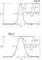
- the spectral filter has a spectral width of 1.5 nm respectively ( Fig. 9 ), 475 pm ( Fig. 10 ) or 250 pm ( Fig. 11 ).
- the spectral filter 8 can be passive or active. In the case of a passive filter, the spectral selection is fixed. In the case of an active filter, the transmission peak can be shifted by acting on an external control parameter such as the displacement or the rotation of a component, the change in temperature or the applied voltage.
- a passive spectral filter thus makes it possible to filter a single wavelength.
- An active spectral filter makes it possible to tune the wavelength, continuously or in steps, over several hundred nanometers included in the emission range of the supercontinuum.
- the spectral filters that can be inserted into the injection module can be classified into different categories.
- the first category includes spatial filters which provide spatial dispersion as a function of wavelength or optical frequency.
- the filters based on a prism or on a diffraction grating provide an angular dispersion as a function of the optical frequency which makes it possible to select the useful wavelength.
- the second category concerns interference filters.
- An interference filter has a maximum transmission for optical frequencies which generate constructive interference. The principle is then to use the interaction with two waves (Fabry-Perot standard) or with multiple waves (multilayer mirrors) to create effects of modulation of the transmission or of the reflectivity of the component. These interference filters use multiple reflections on a number of surfaces. If all the reflected or transmitted waves are in phase, the transmission (or reflection) is maximum. The constructive interference effect being by nature dependent on the wavelength, one obtains variations of the transmission (or of the reflection) as a function of the optical frequency or of the wavelength.
- the third category concerns birefringent filters.
- a birefringent filter is based on interference phenomena by polarization between the waves propagating in a birefringent material respectively along the ordinary axis and the extraordinary axis of this birefringent material.
- the principle of spectral filtering consists in using the extraordinary index which depends on the direction of propagation with respect to the optical axis in a birefringent medium.
- diffractive spectral filter lies between spatial filters and interference filters.
- a diffractive filter uses multiple wave interference typically through periodic variation of the index of the solid material.
- Bragg mirrors and acousto-optical filters Mention may also be made of resonant mirrors, combining a diffraction grating with a dielectric mirror. These diffractive filters have multiple adjustment possibilities to discriminate the output wavelength.
- certain filters can be configured to simultaneously generate several distinct and tunable coherent wavelengths.
- an interference or acousto-optical type filter can be used for this purpose.
- the wavelengths are passively filtered by the interference filter which allows spectral bands regularly spaced apart in wavelength to pass, in the known form of a comb of lines.
- an acousto-optical filter an acoustic wave is generally applied to a crystal to generate a diffracted wavelength. The simultaneous application of several acoustic waves, of different phases, to the crystal of the acousto-optic filter, allows the superposition of different diffracted wavelengths.
- the spacing between these different wavelengths may extend from 0.01 nm up to 100 nm and the number of wavelengths available simultaneously may be between 2 and up to 30. This number of wavelengths can be variable and be modified by controlling certain parameters of the filter.
- the spectral width of each spectral band is generally between 0.01 nm up to 5 nm, and preferably 0.1 nm.
- the wavelength tuning band can be carried out over wide spectral bands ranging from 400 to 700 nm or from 700 to 1200 nm or from 1300 to 1700 or even from 1800 to 2200nm.
- acousto-optical tunable filter it is possible by means of a controller to diffract from one to sixteen wavelengths, with a spectral width of 0.6 nm and separated by at least 1 nm.
- an acousto-optical filter made it possible to simultaneously filter pulses at three distinct wavelengths equal to 1000 nm, 1030 nm and 1100 nm.
- the injection module 10 comprises a supercontinuum source and a spectral filter, as described above.
- the spectral filter 8 not only filters light pulses spectrally over a narrow spectral band (from 250 ⁇ m to 1.5 nm in spectral width), but that this spectral filter 8 also filters temporally. light pulses.
- the light pulses 110 have a duration of the order of a picosecond, for example between 0.1 ps and 100 ps, and preferably from 20 to 50 ps, for 100 pulses emitted by the supercontinuum source with a duration of the order of one nanosecond (between 800ps and 100 ns).
- the duration of the light pulses 110 is inversely proportional to the spectral width of the spectral filter 8.
- This temporal filtering effect has not yet been fully explained.
- a light pulse duration of 3 ps is measured (see Fig. 9 )
- a light pulse duration of 7 ⁇ s is measured (see Fig. 10 )
- a light pulse duration of 11 ⁇ s is measured ( Fig. 11 ).
- the filtering of this supercontinuum radiation results in the reduction of the pulse duration from nanosecond pulses to picosecond pulses, the duration of 110 pulses to output of the spectral filter varying inversely with the spectral width of the spectral filter 8.
- An injection module 10 is thus produced from a supercontinuum source 9, based on a laser 91 emitting pulses at a single wavelength, which are then spectrally extended and linearly chirped, then filtered by means of a spectral filter 8.
- This injection module 10 generates ultrashort light pulses 110 of duration of the order of a picosecond (from 1 to 20 ps approximately), linearly chirped and spectrally filtered over a narrow spectral bandwidth (from 250 ⁇ m to a few nanometers).
- this first example of injection module 10 makes it possible to tune the wavelength of ultrashort light pulses 110 over a wide spectral band of at least a hundred nanometers, up to several hundred nm, in a relatively simple and inexpensive manner.
- the ultrashort light pulses 110 generated by the injection module 10 based on a supercontinuum source 9 and a spectral filter 8 have a power of approximately 20 microwatt to 1 milliwatt.
- the injection module 10 is based on a mode-locking laser tunable in wavelength over a wide spectral range in the infrared, which extends for example from 976 nm to 1030 nm.
- the injection module 10 is based on a mode-locked laser comprising an amplifying non-linear loop mirror (also called NALM for Non Linear Amplifying Loop Mirror).
- an amplifying non-linear loop mirror also called NALM for Non Linear Amplifying Loop Mirror
- the injection module 10 comprises an amplifier nonlinear loop mirror 99.
- the amplifier nonlinear loop mirror 99 is 8-shaped and comprises a first amplifying nonlinear loop 11 and a second amplifying nonlinear loop 12, connected between them by a coupler 5.
- the first amplifying non-linear loop 11 comprises a first optical amplifier 1, for example a section of Ytterbium-doped optical fiber, of single-mode type, of length 10 cm to 1 m, core diameter 6 to 10 microns, a coupler optical multiplexer 6, a spectral filter 8 tunable in wavelength, an optical isolator 4 and an output coupler 15.
- a pump 3 is injected at the input of the optical coupler-multiplexer 6 in the first non-linear loop 11 , so as to optically pump the first optical amplifier 1.
- the second amplifying non-linear loop 12 comprises a second optical amplifier 2, for example a section of Ytterbium-doped optical fiber, of single-mode type, of length 10 cm to 1 m, core diameter 6 to 10 microns, an optical coupler-multiplexer 16 and a passive optical fiber 7, for example a silica fiber having a core diameter of 6 to 10 microns and a length of 10 cm to 20 m.
- a second optical amplifier 2 for example a section of Ytterbium-doped optical fiber, of single-mode type, of length 10 cm to 1 m, core diameter 6 to 10 microns, an optical coupler-multiplexer 16 and a passive optical fiber 7, for example a silica fiber having a core diameter of 6 to 10 microns and a length of 10 cm to 20 m.
- a pump 13 is injected at the input of the optical coupler-multiplexer 16 into the second amplifying non-linear loop 12, so as to optically pump the second optical amplifier 2.
- the pumps 3, 13 are, for example, single-mode fiber diodes.
- a spectral filter 8 has been placed inside the cavity of the mode-locked laser.
- the spectral filter 8 is an optical filter having a passband tunable in wavelength over a wide spectral range in the infrared. , as described in connection with the first example.
- the passband of the spectral filter is limited, for example less than 3 nm or 1 nm or even 0.5 nm, or even 250 ⁇ m.
- the spectral filter 8 tunable in wavelength comprises an interference filter, an acousto-optical filter or an acousto-optical filter in thin layers.
- the spectral filter 8 can be tunable in wavelength by electronic and / or mechanical control means over a wide spectral band of at least a hundred nanometers, up to several hundreds of nm.
- the first optical amplifier 1 and / or the second optical amplifier 2 are optical amplifiers with a wide spectral band. More precisely, instead of using an amplifying fiber of the alumino-silicate type, an optical fiber doped with erbium and codoped phosphorus is selected so that the amplification spectral band of this optical fiber extends over at least a wide range. near infrared spectral band from 976 nm to 1030 nm.
- broad spectral band is meant here a spectral band extending over at least a hundred nanometers and being able to extend over several hundreds of nanometers.
- the first optical amplifier 1, the second optical amplifier 2 and the optical fiber 7 have a normal dispersion, that is to say a negative dispersion, for example between -100 to 0 ps / km / nm for silica.
- an injection module 10 based on a mode-locked laser comprising an amplifying nonlinear loop mirror 99 and a spectral filter 8 delivers ultrashort light pulses 110, of duration less than about 10 ps, linearly chirped, at a a rate of a few MHz, spectrally filtered with a spectral width of the order of a nanometer and tunable in wavelength between 976 nm and 1030 nm, and having a power of about a few milliwatts.
- the injection module 10 is based on a mode-locked laser comprising a nonlinear loop mirror (also called NOLM for Non Linear Amplifying Loop Mirror) comprising only the first amplifying loop 11.
- NOLM Non Linear Amplifying Loop Mirror
- the dispersive component 7 is placed in loop 11.
- An injection module 10 was thus produced, based on a supercontinuum source, as illustrated in figure 2 , or according to the invention on a mirror with a nonlinear loop, as illustrated on figure 3 .
- the injection module 10 generates ultrashort light pulses 110, of duration less than about 10 ps, linearly chirped, spectrally filtered, the ultrashort pulses having a spectral width of the order of a nanometer, and tunable in wavelength over a spectral band of several tens of nanometers, for example between 976 nm and 1030 nm, by means of the tunable spectral filter 8.
- the injection module 10 delivers ultrashort light pulses 110 of low spectral width (having a spectral width of about 1 nm), which can then be injected into an amplification module.
- the preamplification module comprises an optical isolator 14, a multiplexer coupler 26, a pump 23, an optical amplifier 21 and another optical isolator 24.
- the preamplification module receives the ultrashort light pulses 110 from the injection module 10 and generates, by optical amplification, pre-amplified ultrashort light pulses 120.
- the optical amplifier 21 is an optical fiber amplifier, for example with a rare earth doped optical fiber.
- the same injection module 10 can inject ultrashort light pulses to different optical amplifiers associated respectively with different emission bands. To do this, it suffices to tune the wavelength of the spectral filter 8 of the injection module as a function of the gain band of the optical amplifier selected.
- MOPA Master-Oscillator-Power-Amplifier
- the power amplification module which can be placed at the output of an injection module 10 or at the output of a preamplification module.
- the power amplification module comprises an optical isolator 34, a multiplexer coupler 36, a pump 33, an optical amplifier 31 and another optical isolator 44.
- the power amplification module receives for example the pre-amplified ultrashort light pulses 120 of the preamplification module and generates, by optical amplification, amplified ultrashort light pulses 130.
- the optical amplifier 31 is an optical fiber amplifier, for example a rare earth doped optical fiber.
- a Ytterbium-doped fiber amplifier is used allowing amplification at a wavelength around 1 ⁇ m.
- a wavelength tuning range of the order of 100 nm ranging from 1020 nm to 1120 nm
- pulses of variable duration between 3 ps and 20 ps.
- the duration of the pulses is limited by the filter used.
- Another solid amplifying medium is in particular based on a neodymium crystal: YAG (Nd: YAG) for the spectral range around 1064 ⁇ m (doubled in frequency to obtain a wavelength of 532 nm).
- YAG neodymium crystal
- an amplifying medium based on fosterite (emission wavelength at 1200 nm, then doubled in frequency at 600 nm), or erbium: YAG (Er: YAG) emitting around 3 ⁇ m or the alexandrite emitting at 755 nm and doubled in frequency to 380nm or the ruby emitting at 694 and doubled in frequency at 350 nm.
- fosterite emission wavelength at 1200 nm, then doubled in frequency at 600 nm
- Another operating mode can also be based on different optical fiber amplifiers doped respectively with different rare earths to cover different spectral ranges: in particular a praseodymium doped fiber: emitting in the 488-900 mn and 1300nm range, a neodymium codoped fiber -ytterbium emitting in the 890-940 nm and / or 976-1200nm range, a holmium doped fiber emitting in the 2100-2200nm range, an Erbium doped fiber emitting in the 1460-1600nm range and / or a thulium doped fiber emitting in the 1600-2200 nm range.
- a praseodymium doped fiber emitting in the 488-900 mn and 1300nm range
- the injection module 10 can deliver pulses 110 at a very high rate from 20 kHz to 50 MHz.
- pulses 110 at a very high rate from 20 kHz to 50 MHz.
- intense and ultrashort pulse trains are produced inside an envelope controlled by the duration and rate of the pump flash of the amplifier.
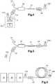
- One represented on the figure 8 a system for generating ultrashort light pulses tunable in wavelength according to another exemplary embodiment of the invention.
- the system has several different optical amplifiers 31, 32, 33, 34 (based on solid glass or crystal media) arranged in a star around a flash lamp in most likely multi-pass arrangements.
- This set of optical amplifiers 31, 32, 33, 34 is injected by a single injection module 10 which is wavelength tunable and selectively routed to one or the other of the optical amplifiers 31, 32, 33 , 34.
- a filtering-routing can be achieved by means of prisms 60-66 or suitable diffractive elements and / or semi-reflecting blades 50, 51, 52.
- Other semi-reflecting blades 54, 55 and mirrors 53, 56 make it possible to recombine the different amplified beams towards the same output.
- a non-linear optical medium 41 can be inserted at the output of the device to achieve the frequency conversion required for the delivery of the appropriate wavelength according to the desired application.
- the figure 6 schematically represents another embodiment of a system for generating ultra-short light pulses tunable in wavelength.
- the system for generating wavelength tunable ultrashort light pulses comprises an injection module 10, a pre-amplification module 20 and / or a power amplification module 30 and a module frequency converter 40.
- the injection module 10, the pre-amplification module 20, the power amplification module 30 and the frequency converter module 40 are arranged in series.
- An optical isolator 44 is disposed between the power amplification module 30 and the frequency converter module 40.
- ultrashort amplified pulses 130 are obtained, with a duration of between approximately 1 ps and 20 ps, tunable in wavelength over a hundred nanometers up to approximately 300 nm and intense at 1 kW. at 1 MW in peak power.
- the frequency converter module 40 is based on a non-linear optical component arranged downstream of the optical amplification module 30.
- a non-linear four-wave degenerate mixing effect DFWM for Degenerated Four Wave Mixing
- the non-linear optical component 40 produces a signal 140 at the double frequency of the amplified pulses 130.
- the non-linear optical component 40 also produces a complementary wave 141 (also called idler ) .
- the signal 140 is emitted at a wavelength included in the visible range and which can range from yellow to red over a spectral range of 550 to 700 nm until now inaccessible.
- the amplified pulses 130 have sufficient intensity for the frequency conversion by four-wave mixing to be highly efficient.
- FWM Four Wave Mixing
- DFWM Degenerate Four-Wave Mixing
- PCF photonic crystal fibers
- the FWM is capable of delivering a power greater than ten Watts at a specific wavelength.
- very high power spectral densities of the order of W / nm, can be obtained through this process.
- the figure 7 illustrates an example of an ultrashort and spectrally filtered pulse generation system combined with a frequency converter module.
- the system of figure 7 is based primarily on fiber optic components. More precisely, the system of figure 7 comprises a supercontinuum source 9 and a spectral filter 8 tunable in wavelength, as described in connection with the figure 2 .
- the system comprises in series a first optical preamplifier 21, a second optical preamplifier 22, an optical power amplifier 30, and a non-linear optical component 40.
- the optical component 40 is for example a photonic crystal fiber (PCF).
- Optical isolators 14, 24, 34, 44 are arranged between the different modules of the system.
- the non-linear optical component 40 receives the ultrashort, spectrally filtered and amplified light pulses and generates a signal wave 140 and a complementary wave 141 (also called idler ), the sum of the optical frequencies of the signal wave 140 and of the complementary wave 141 being equal to the optical frequency of the pump wave.
- a signal is obtained comprising light pulses 140 in the visible range from 510 to 620 nm and / or a complementary one comprising light pulses 141 in the infrared range from 1.8 to 5 microns.
- the pulse generation system shown in figure 7 has the advantage of being robust and compact. The applications of this system are very varied.
- the pulse generation system is of particular interest for medical applications.
- this system makes it possible to deliver energy radiation with pulses that are both ultrashort (of the order of a picosecond), having a low spectral width (of the order of 1 nm) and a tunable central wavelength. over a very wide spectral range (from UV close to ⁇ 300nnm to several microns).
- the architecture of the tunable injection module makes it possible to envisage numerous medical applications, particularly in dermatology, where the adjustment of the wavelength is necessary for the optimization of the treatment.
- This wavelength tunability over a wide spectral range makes it possible to adapt the parameters of the ultrashort light pulses delivered as a function of the operating conditions, for example to treat a stain or a skin defect.
- Different optical amplifiers suitable for amplifying pulses in different ranges of wavelengths can be assembled around common pumping means (flash lamp, diodes or the like). This amplification system is injected by a single injection module which has a broadband spectrum. The tunability of the assembly is based on the extremely wide spectrum of this injector and the average power on the use of high gain amplifying media.
- the ultrashort pulse duration allows the pulse generation system to be combined with a non-linear optical frequency conversion component. This frequency conversion thus allows the spectrum generated by the complete system to be extended very significantly.
- the figures 9 to 11 represent spectral profile measurements of ultrashort light pulses tunable in wavelength, obtained using an optical spectrum analyzer and respectively temporal profile measurements of these pulses, obtained by autocorrelator, for different spectral widths of the tunable filter 8.
- amplified pulses are measured at the output of a pulse generation system as detailed in connection with the figure 1 .
- the spectral width of the pulses is determined by the spectral width of the tunable filter 8.
- the system thus makes it possible to generate pulses having both an ultrashort duration (of about 1 picosecond at 11 ps) and a very narrow spectral width of 1.5 nm, 475 pm and 250 pm, respectively, at a central wavelength of about 1030 nm.
- the system makes it possible to generate ultrashort laser pulses of picosecond duration, of very narrow spectral width. These pulses are tunable in wavelength over a range of several tens to hundreds of nanometers. These pulses can be amplified so that we obtain picosecond pulses with very high power spectral density tunable in wavelength over a wide spectral range from ultraviolet (300 nm) to infrared (up to 10 microns) ).
Landscapes
- Physics & Mathematics (AREA)
- Electromagnetism (AREA)
- Optics & Photonics (AREA)
- Nonlinear Science (AREA)
- Engineering & Computer Science (AREA)
- Plasma & Fusion (AREA)
- General Physics & Mathematics (AREA)
- Spectroscopy & Molecular Physics (AREA)
- Optical Modulation, Optical Deflection, Nonlinear Optics, Optical Demodulation, Optical Logic Elements (AREA)
- Lasers (AREA)
Claims (12)
- System zur Erzeugung wellenlängenabstimmbarer, ultrakurzer Lichtimpulse in einem Spektralbereich zwischen Ultraviolett und Infrarot, dadurch gekennzeichnet, daß das System folgendes aufweist:- ein Einkopplungsmodul (10) mit einer Lichtquelle (9, 99) und einem wellenlängenabstimmbaren Spektralfilter (8),- wobei die Lichtquelle (9, 99) dazu ausgelegt ist, kurze Lichtimpulse (100) mit einer Dauer zwischen mehreren Hundert Pikosekunden und etwa Hundert Nanosekunden zu erzeugen, wobei sich die kurzen Lichtimpulse (100) über ein spektrales Ausstrahlungsband mit einer spektralen Breite von mehreren Zehnereinheiten von Nanometern bis mehrere Hundert Nanometer erstrecken,- wobei der Spektralfilter (8) wenigstens ein durch eine zentrale Wellenlänge und eine spektrale Breite zwischen 10 pm und 10 nm definiertes spektrales Durchlaßband aufweist und die zentrale Wellenlänge des spektralen Durchlaßbands in einem im spektralen Ausstrahlungsband der Lichtquelle (9, 99) liegenden spektralen Bereich abstimmbar ist, wobei der Spektralfilter (8) dazu ausgelegt ist, die kurzen Lichtimpulse (100) spektral zu filtern und in ein Zeitformat zu bringen, damit das Einkopplungsmodul (10) spektral gefilterte und in Abhängigkeit von der zentralen Wellenlänge des spektralen Durchlaßbands wellenlängenabstimmbare ultrakurze Lichtimpulse (110) mit einer Dauer in der Größenordnung einer Pikosekunde erzeugt; und- wenigstens einen am Ausgang des Einkopplungsmoduls (10) angeordneten optischen Verstärker (20, 21, 22, 30, 31, 32, 33, 34), wobei der wenigstens eine optische Verstärker dazu ausgelegt ist, die spektral gefilterten und wellenlängenabstimmbaren ultrakurzen Lichtimpulse (110) zu empfangen und durch optische Verstärkung spektral gefilterte und in Abhängigkeit von der zentralen Wellenlänge des spektralen Durchlaßbands des Spektralfilters (8) wellenlängenabstimmbare ultrakurze verstärkte Impulse (120, 130) zu erzeugen,- wobei die Lichtquelle (9, 99) einen Verstärkerspiegel mit nichtlinearer Schleife (99) aufweist, wobei der Verstärkerspiegel mit nichtlinearer Schleife (99) einen auf der optischen Strecke des Spiegels mit nichtlinearer Schleife angeordneten weiteren optischen Verstärker (1) aufweist und der Spektralfilter (8) auf der Strecke des Spiegels mit nichtlinearer Schleife (99) angeordnet ist.
- System zur Erzeugung ultrakurzer Lichtimpulse gemäß Anspruch 1, bei dem der Verstärkerspiegel mit nicht linearer Schleife (99) die Form einer Acht aufweist und eine erste bidirektionale nichtlineare Verstärkerschleife (11) und eine zweite unidirektionale nichtlineare Schleife (12) aufweist, wobei der Spektralfilter (8) in der ersten nichtlinearen Schleife (11) angeordnet ist.
- System zur Erzeugung ultrakurzer Lichtimpulse gemäß einem der Ansprüche 1 bis 2, bei dem der Spektralfilter (8) einen Filter auf der Basis eines Prismas, einen Filter auf der Basis eines Beugungsgitters, einen Interferenzfilter, einen doppelbrechenden Filter, einen Beugungsfilter mit Bragg-Spiegel, einen Beugungsfilter mit Resonanzspiegel, einen akusto-optischen Filter oder einen akusto-optischen Dünnschichtfilter aufweist.
- System zur Erzeugung ultrakurzer Lichtimpulse gemäß Anspruch 3, bei dem der Spektralfilter (8) ein Interferenzfilter oder ein akusto-optischer Filter ist, der dazu ausgelegt ist, eine Anzahl von spektral voneinander beabstandeten spektralen Duchlaßbändern gleichzeitig zu filtern, wobei jedes spektrale Durchlaßband durch eine zentrale Wellenlänge und eine spektrale Breite zwischen 10 pm und 10 nm definiert ist und wobei jede zentrale Wellenlänge des Spektralfilters (8) in einem innerhalb des spektralen Ausstrahlungsbands der Lichtquelle (9, 99) liegenden Spektralbereich abstimmbar ist.
- System zur Erzeugung ultrakurzer Lichtimpulse gemäß Anspruch 3 oder 4, bei dem der Spektralfilter (8) eine spektrale Breite von weniger als 1 nm aufweist.
- System zur Erzeugung ultrakurzer Lichtimpulse gemäß einem der Ansprüche 1 bis 5, bei dem der wenigstens eine optische Verstärker eine Anzahl von sternförmig angeordneten optischen Verstärkern (31, 32, 33, 34) und/oder einen mit einem Glasfaserleistungsverstärker (30) in Reihe angeordneten Glasfaservorverstärker (20, 21, 22) aufweist.
- System zur Erzeugung ultrakurzer Lichtimpulse gemäß einem der Ansprüche 1 bis 6, bei dem die Lichtquelle (9, 99), der Spektralfilter (8) und/oder der wenigstens eine optische Verstärker (20, 30) Glasfaserbauelemente aufweisen.
- System zur Erzeugung ultrakurzer Lichtimpulse gemäß einem der Ansprüche 1 bis 7, bei dem der wenigstens eine optische Verstärker (20, 30) eine mit Seltenerdmaterial dotierte Glasfaser aufweist.
- System zur Erzeugung ultrakurzer Lichtimpulse gemäß einem der Ansprüche 1 bis 8, das außerdem
ein am Ausgang des wenigstens einen optischen Verstärkers (20, 30) angeordnetes optisches Streuelement (40) mit negativer Streuung aufweist,
wobei das optische Streuelement (40) dazu ausgelegt ist, einen Pumpimpuls und einen ultrakurzen verstärkten Impuls (120, 130) gleichzeitig zu empfangen und durch einen nichtlinearen optischen Effekt einer Vierwellenmischung ein erstes optisches Signal und ein zweites optisches Signal zu erzeugen, wobei das erste optische Signal oder das zweite optische Signal einen Ausgangslichtimpuls (140, 141) mit einer Dauer in der Größenordnung von einer Pikosekunde bis etwa 100 Pikosekunden und mit einer vorbestimmten Wellenlänge im Bereich des Ultraviolett, des sichtbaren Lichts oder des Infrarot und mit einer spektralen Breite von weniger als 10 nm aufweist, wobei die vorbestimmte Wellenlänge des Ausgangslichtimpulses (140, 141) in Abhängigkeit von der zentralen Wellenlänge des Spektralfilters (8) abstimmbar ist. - System zur Erzeugung ultrakurzer Lichtimpulse gemäß Anspruch 9, bei dem das optische Streuelement (40) einen Abschnitt mit photonischer optischer Faser aufweist.
- Verfahren zur Erzeugung wellenlängenabstimmbarer, ultrakurzer Lichtimpulse in einem Spektralbereich zwischen Ultraviolett und Infrarot mit den folgenden Schritten:- Erzeugen von kurzen Lichtimpulsen (100) mit einer Dauer zwischen mehreren Hundert Pikosekunden und etwa Hundert Nanosekunden mittels einer Lichtquelle (99), wobei sich die kurzen Lichtimpulse (100) über ein spektrales Ausstrahlungsband mit einer spektralen Breite von mehreren Zehnereinheiten von Nanometern bis mehrere Hundert Nanometer erstrecken,- spektrales Filtern der kurzen Impulse (100) in wenigstens einem durch eine zentrale Wellenlänge und eine spektrale Breite zwischen 10 pm und 10 nm definierten spektralen Durchlaßband mittels eines wellenlängenabstimmbaren und auf der optischen Strecke eines Verstärkerspiegels mit nicht linearer Schleife (99) angeordneten Spektralfilters (8), wobei die zentrale Wellenlänge des spektralen Durchlaßbands innerhalb eines innerhalb des spektralen Ausstrahlungsbands liegenden Spektralbereichs abstimmbar ist, wobei das spektrale Filtern dazu ausgelegt ist, die kurzen Lichtimpulse (100) spektral zu filtern und zeitmäßig in eine Form zu bringen, um spektral gefilterte und in Abhängigkeit von der zentralen Wellenlänge des spektralen Durchlaßbands wellenlängenabstimmbare ultrakurze Lichtimpulse (110) von einer Dauer in der Größenordnung der Pikosekunde zu erzeugen, und- eine erste optische Verstärkung der spektral gefilterten ultrakurzen Impulse (110) mittels eines auf der optischen Strecke eines Verstärkerspiegels mit nicht linearer Schleife (99) angeordneten optischen Verstärkers, um spektral gefilterte und in Abhängigkeit von der zentralen Wellenlänge des spektralen Durchlaßbands des Spektralfilters wellenlängenabstimmbare, verstärkte ultrakurze Lichtimpulse (120, 130) zu erzeugen, und- eine weitere optische Verstärkung mittels wenigstens eines weiteren, auf einer optischen Strecke am Ausgang des Verstärkerspiegels mit nicht linearer Schleife (99) angeordneten optischen Verstärkers (20, 21, 22, 30, 31, 32, 33, 34).
- System zur Erzeugung wellenlängenabstimmbarer, ultrakurzer Lichtimpulse gemäß Anspruch 11, das außerdem folgenden Schritt aufweist:
Erzeugen eines ersten optischen Signals und eines zweiten optischen Signals aus einem Pumpimpuls und einem verstärkten ultrakurzen Impuls (120, 130) durch einen nichtlinearen optischen Effekt mit Vierwellenmischung in einem am Ausgang des wenigstens einen weiteren optischen Verstärkers angeordneten optischen Streuelement (40) mit negativer Streuung, wobei das erste und das zweite optische Signal einen ultrakurzen Ausgangslichtimpuls (140, 141) mit einer Dauer in der Größenordnung von einer Pikosekunde bis etwa 100 Pikosekunden und mit einer vorbestimmten Wellenlänge im Bereich des Ultraviolett, des sichtbaren Lichts oder des Infrarot und mit einer spektralen Breite von weniger als 10 nm aufweisen, wobei die vorbestimmte Wellenlänge des ultrakurzen Ausgangslichtimpulses (140, 141) in Abhängigkeit von der zentralen Wellenlänge des Spektralfilters (8) abstimmbar ist.
Applications Claiming Priority (2)
| Application Number | Priority Date | Filing Date | Title |
|---|---|---|---|
| FR1463399A FR3031246B1 (fr) | 2014-12-29 | 2014-12-29 | Systeme et procede de generation d'impulsions lumineuses ultrabreves a forte densite spectrale de puissance et accordables en longueur d'onde |
| PCT/FR2015/053751 WO2016108020A1 (fr) | 2014-12-29 | 2015-12-24 | Système et procédé de génération d'impulsions lumineuses ultrabrèves à forte densité spectrale de puissance et accordables en longueur d'onde |
Publications (2)
| Publication Number | Publication Date |
|---|---|
| EP3241259A1 EP3241259A1 (de) | 2017-11-08 |
| EP3241259B1 true EP3241259B1 (de) | 2020-11-11 |
Family
ID=53758250
Family Applications (1)
| Application Number | Title | Priority Date | Filing Date |
|---|---|---|---|
| EP15823717.2A Active EP3241259B1 (de) | 2014-12-29 | 2015-12-24 | System und verfahren zur erzeugung wellenlängenabstimmbarer, ultrakurzer lichtpulse mit hoher leistungsspektraldichte |
Country Status (5)
| Country | Link |
|---|---|
| US (1) | US10250006B2 (de) |
| EP (1) | EP3241259B1 (de) |
| CA (1) | CA2972572A1 (de) |
| FR (1) | FR3031246B1 (de) |
| WO (1) | WO2016108020A1 (de) |
Cited By (1)
| Publication number | Priority date | Publication date | Assignee | Title |
|---|---|---|---|---|
| EP4459371A1 (de) * | 2023-05-05 | 2024-11-06 | Instytut Chemii Fizycznej PAN | Weitreichend abstimmbare laserquelle, die den parametrischen, nichtlinearen effekt der wellenmischung mit gechirpten impulsen nutzt, und verfahren zur breitbandigen, abstimmbaren laserquelle, die den parametrischen, nichtlinearen effekt der wellenmischung mit gechirpten impulsen nutzt |
Families Citing this family (13)
| Publication number | Priority date | Publication date | Assignee | Title |
|---|---|---|---|---|
| JP6839787B2 (ja) | 2017-09-29 | 2021-03-10 | エーエスエムエル ネザーランズ ビー.ブイ. | 放射源 |
| US11777610B2 (en) * | 2018-02-07 | 2023-10-03 | Attochron, Llc | Method and apparatus for ultra-short pulsed laser communication through a lossy medium |
| US11009455B2 (en) * | 2018-07-31 | 2021-05-18 | Applied Materials, Inc. | Precursor delivery system and methods related thereto |
| WO2020092707A2 (en) * | 2018-11-01 | 2020-05-07 | Ofs Fitel, Llc | Wavelength-swept light source |
| ES2968458T3 (es) * | 2019-04-25 | 2024-05-09 | Fyla Laser S L | Un sistema y método de configuración de todo fibras para generar una emisión pulsada de supercontinuo temporalmente coherente |
| US11276982B2 (en) * | 2020-01-22 | 2022-03-15 | Cybel, LLC. | Optical fiber amplifier for operation in two micron wavelength region |
| JP7372190B2 (ja) * | 2020-03-27 | 2023-10-31 | 株式会社アドバンテスト | レーザ光出力装置 |
| CN112751257A (zh) * | 2020-12-31 | 2021-05-04 | 杭州谱育科技发展有限公司 | 激光晶体、固体激光器及其应用 |
| US12548971B2 (en) * | 2021-01-25 | 2026-02-10 | Applied Energetics, Inc. | Selectable wavelength cascading coherent optical pump sources |
| CN113725705B (zh) * | 2021-08-25 | 2022-07-08 | 吉林大学 | 一种基于光谱整形的绿光脉冲源 |
| CN115224578B (zh) * | 2022-07-20 | 2025-07-11 | 北京维快光子科技有限公司 | 光纤锁模激光器和激光设备 |
| US20250147382A1 (en) * | 2023-11-07 | 2025-05-08 | Iism Inc. | Tunable duv laser system using angle-dependent wavelength selector |
| CN117471720B (zh) * | 2023-12-27 | 2024-04-09 | 武汉中科锐择光电科技有限公司 | 一种基于声光延时线的超短脉冲整形装置 |
Family Cites Families (3)
| Publication number | Priority date | Publication date | Assignee | Title |
|---|---|---|---|---|
| KR100205052B1 (ko) * | 1996-07-12 | 1999-06-15 | 정선종 | 파장 가변형 모드록킹 광섬유 레이저 |
| US7804864B2 (en) * | 2004-03-31 | 2010-09-28 | Imra America, Inc. | High power short pulse fiber laser |
| US9240663B2 (en) * | 2013-11-14 | 2016-01-19 | Coherent, Inc. | Tunable femtosecond laser-pulse source including a super-continuum generator |
-
2014
- 2014-12-29 FR FR1463399A patent/FR3031246B1/fr active Active
-
2015
- 2015-12-24 CA CA2972572A patent/CA2972572A1/fr not_active Abandoned
- 2015-12-24 US US15/540,734 patent/US10250006B2/en active Active
- 2015-12-24 EP EP15823717.2A patent/EP3241259B1/de active Active
- 2015-12-24 WO PCT/FR2015/053751 patent/WO2016108020A1/fr not_active Ceased
Non-Patent Citations (1)
| Title |
|---|
| None * |
Cited By (1)
| Publication number | Priority date | Publication date | Assignee | Title |
|---|---|---|---|---|
| EP4459371A1 (de) * | 2023-05-05 | 2024-11-06 | Instytut Chemii Fizycznej PAN | Weitreichend abstimmbare laserquelle, die den parametrischen, nichtlinearen effekt der wellenmischung mit gechirpten impulsen nutzt, und verfahren zur breitbandigen, abstimmbaren laserquelle, die den parametrischen, nichtlinearen effekt der wellenmischung mit gechirpten impulsen nutzt |
Also Published As
| Publication number | Publication date |
|---|---|
| FR3031246A1 (fr) | 2016-07-01 |
| WO2016108020A1 (fr) | 2016-07-07 |
| US20170352999A1 (en) | 2017-12-07 |
| FR3031246B1 (fr) | 2018-02-09 |
| CA2972572A1 (fr) | 2016-07-07 |
| EP3241259A1 (de) | 2017-11-08 |
| US10250006B2 (en) | 2019-04-02 |
Similar Documents
| Publication | Publication Date | Title |
|---|---|---|
| EP3241259B1 (de) | System und verfahren zur erzeugung wellenlängenabstimmbarer, ultrakurzer lichtpulse mit hoher leistungsspektraldichte | |
| EP3488290B1 (de) | System zum erzeugen von kurzen oder ultrakurzen lichtimpulsen | |
| EP2630705B1 (de) | Laseremissionsvorrichtung und verfahren zur spektroskopischen analyse einer probe | |
| FR3076959A1 (fr) | Systeme laser et procede de generation d'impulsions laser de tres haute cadence | |
| EP2929603B1 (de) | System und verfahren zur erzeugung einer folge von ultrakurzen hochleistungslaserimpulsen | |
| EP2837071B1 (de) | System und verfahren zur optischen verstärkung von ultrakurzen lichtimpulsen jenseits der grenze des spektralen verstärkungsbandes | |
| EP1766735B1 (de) | Verstärkerkette zum erzeugen ultrakurzer lichtimpulse verschiedener breite | |
| EP2311158B1 (de) | Vorrichtung zur erzeugung eines laserimpulses von kurzer dauer | |
| EP2695253B1 (de) | Optischer faserlaser | |
| EP4291949A1 (de) | System und verfahren zur erzeugung eines lichtimpulses mit subpikosekundendauer, die eine dauer und/oder eine wiederholungsfrequenz einstellbar ist | |
| FR2611320A1 (fr) | Generateur laser a modes verrouilles en phase | |
| EP4348776B1 (de) | Mamychev-laseroszillator zur erzeugung ultrakurzer impulse und vorrichtung zum starten davon | |
| EP2443706B1 (de) | Generator und lasersystem mit gekoppelten subkavitäten | |
| EP3100113B1 (de) | Optischer parametrischer ultrakurzer impulsverstärker | |
| EP1474849A1 (de) | Verstärkerkette zur erzeugung von ultrakurzen hochleistungsimpulsen | |
| FR2965674A1 (fr) | Procede de generation d'un rayonnement laser de courte duree (<100ns) de puissance moyenne p et a une cadence elevee (>50khz) | |
| WO2021009323A1 (fr) | Système de génération d'impulsion lumineuse ultra-courte de forte énergie avec module de mise en forme spectrale | |
| FR2903819A1 (fr) | Dispositif d'etirement et de controle spectral pour lasers impulsionnels a forte puissance crete |
Legal Events
| Date | Code | Title | Description |
|---|---|---|---|
| STAA | Information on the status of an ep patent application or granted ep patent |
Free format text: STATUS: THE INTERNATIONAL PUBLICATION HAS BEEN MADE |
|
| PUAI | Public reference made under article 153(3) epc to a published international application that has entered the european phase |
Free format text: ORIGINAL CODE: 0009012 |
|
| STAA | Information on the status of an ep patent application or granted ep patent |
Free format text: STATUS: REQUEST FOR EXAMINATION WAS MADE |
|
| 17P | Request for examination filed |
Effective date: 20170629 |
|
| AK | Designated contracting states |
Kind code of ref document: A1 Designated state(s): AL AT BE BG CH CY CZ DE DK EE ES FI FR GB GR HR HU IE IS IT LI LT LU LV MC MK MT NL NO PL PT RO RS SE SI SK SM TR |
|
| AX | Request for extension of the european patent |
Extension state: BA ME |
|
| DAV | Request for validation of the european patent (deleted) | ||
| DAX | Request for extension of the european patent (deleted) | ||
| GRAP | Despatch of communication of intention to grant a patent |
Free format text: ORIGINAL CODE: EPIDOSNIGR1 |
|
| STAA | Information on the status of an ep patent application or granted ep patent |
Free format text: STATUS: GRANT OF PATENT IS INTENDED |
|
| RIC1 | Information provided on ipc code assigned before grant |
Ipc: G02F 1/35 20060101ALN20200529BHEP Ipc: H01S 3/11 20060101ALN20200529BHEP Ipc: H01S 3/00 20060101AFI20200529BHEP Ipc: H01S 3/08 20060101ALN20200529BHEP Ipc: G02F 1/11 20060101ALI20200529BHEP Ipc: G02F 1/39 20060101ALI20200529BHEP Ipc: H01S 3/067 20060101ALN20200529BHEP Ipc: H01S 3/16 20060101ALN20200529BHEP |
|
| RIC1 | Information provided on ipc code assigned before grant |
Ipc: G02F 1/39 20060101ALI20200608BHEP Ipc: H01S 3/11 20060101ALN20200608BHEP Ipc: G02F 1/11 20060101ALI20200608BHEP Ipc: H01S 3/08 20060101ALN20200608BHEP Ipc: G02F 1/35 20060101ALN20200608BHEP Ipc: H01S 3/16 20060101ALN20200608BHEP Ipc: H01S 3/067 20060101ALN20200608BHEP Ipc: H01S 3/00 20060101AFI20200608BHEP |
|
| INTG | Intention to grant announced |
Effective date: 20200626 |
|
| RAP1 | Party data changed (applicant data changed or rights of an application transferred) |
Owner name: CENTRE NATIONAL DE LA RECHERCHE SCIENTIFIQUE Owner name: UNIVERSITE DE BORDEAUX |
|
| GRAS | Grant fee paid |
Free format text: ORIGINAL CODE: EPIDOSNIGR3 |
|
| GRAA | (expected) grant |
Free format text: ORIGINAL CODE: 0009210 |
|
| STAA | Information on the status of an ep patent application or granted ep patent |
Free format text: STATUS: THE PATENT HAS BEEN GRANTED |
|
| AK | Designated contracting states |
Kind code of ref document: B1 Designated state(s): AL AT BE BG CH CY CZ DE DK EE ES FI FR GB GR HR HU IE IS IT LI LT LU LV MC MK MT NL NO PL PT RO RS SE SI SK SM TR |
|
| REG | Reference to a national code |
Ref country code: GB Ref legal event code: FG4D Free format text: NOT ENGLISH |
|
| REG | Reference to a national code |
Ref country code: CH Ref legal event code: EP |
|
| REG | Reference to a national code |
Ref country code: AT Ref legal event code: REF Ref document number: 1334348 Country of ref document: AT Kind code of ref document: T Effective date: 20201115 |
|
| REG | Reference to a national code |
Ref country code: DE Ref legal event code: R096 Ref document number: 602015061949 Country of ref document: DE |
|
| REG | Reference to a national code |
Ref country code: IE Ref legal event code: FG4D Free format text: LANGUAGE OF EP DOCUMENT: FRENCH |
|
| REG | Reference to a national code |
Ref country code: NL Ref legal event code: MP Effective date: 20201111 |
|
| REG | Reference to a national code |
Ref country code: AT Ref legal event code: MK05 Ref document number: 1334348 Country of ref document: AT Kind code of ref document: T Effective date: 20201111 |
|
| PG25 | Lapsed in a contracting state [announced via postgrant information from national office to epo] |
Ref country code: PT Free format text: LAPSE BECAUSE OF FAILURE TO SUBMIT A TRANSLATION OF THE DESCRIPTION OR TO PAY THE FEE WITHIN THE PRESCRIBED TIME-LIMIT Effective date: 20210311 Ref country code: RS Free format text: LAPSE BECAUSE OF FAILURE TO SUBMIT A TRANSLATION OF THE DESCRIPTION OR TO PAY THE FEE WITHIN THE PRESCRIBED TIME-LIMIT Effective date: 20201111 Ref country code: FI Free format text: LAPSE BECAUSE OF FAILURE TO SUBMIT A TRANSLATION OF THE DESCRIPTION OR TO PAY THE FEE WITHIN THE PRESCRIBED TIME-LIMIT Effective date: 20201111 Ref country code: NO Free format text: LAPSE BECAUSE OF FAILURE TO SUBMIT A TRANSLATION OF THE DESCRIPTION OR TO PAY THE FEE WITHIN THE PRESCRIBED TIME-LIMIT Effective date: 20210211 Ref country code: GR Free format text: LAPSE BECAUSE OF FAILURE TO SUBMIT A TRANSLATION OF THE DESCRIPTION OR TO PAY THE FEE WITHIN THE PRESCRIBED TIME-LIMIT Effective date: 20210212 |
|
| PG25 | Lapsed in a contracting state [announced via postgrant information from national office to epo] |
Ref country code: AT Free format text: LAPSE BECAUSE OF FAILURE TO SUBMIT A TRANSLATION OF THE DESCRIPTION OR TO PAY THE FEE WITHIN THE PRESCRIBED TIME-LIMIT Effective date: 20201111 Ref country code: BG Free format text: LAPSE BECAUSE OF FAILURE TO SUBMIT A TRANSLATION OF THE DESCRIPTION OR TO PAY THE FEE WITHIN THE PRESCRIBED TIME-LIMIT Effective date: 20210211 Ref country code: PL Free format text: LAPSE BECAUSE OF FAILURE TO SUBMIT A TRANSLATION OF THE DESCRIPTION OR TO PAY THE FEE WITHIN THE PRESCRIBED TIME-LIMIT Effective date: 20201111 Ref country code: SE Free format text: LAPSE BECAUSE OF FAILURE TO SUBMIT A TRANSLATION OF THE DESCRIPTION OR TO PAY THE FEE WITHIN THE PRESCRIBED TIME-LIMIT Effective date: 20201111 Ref country code: IS Free format text: LAPSE BECAUSE OF FAILURE TO SUBMIT A TRANSLATION OF THE DESCRIPTION OR TO PAY THE FEE WITHIN THE PRESCRIBED TIME-LIMIT Effective date: 20210311 Ref country code: LV Free format text: LAPSE BECAUSE OF FAILURE TO SUBMIT A TRANSLATION OF THE DESCRIPTION OR TO PAY THE FEE WITHIN THE PRESCRIBED TIME-LIMIT Effective date: 20201111 |
|
| REG | Reference to a national code |
Ref country code: LT Ref legal event code: MG9D |
|
| PG25 | Lapsed in a contracting state [announced via postgrant information from national office to epo] |
Ref country code: HR Free format text: LAPSE BECAUSE OF FAILURE TO SUBMIT A TRANSLATION OF THE DESCRIPTION OR TO PAY THE FEE WITHIN THE PRESCRIBED TIME-LIMIT Effective date: 20201111 |
|
| PG25 | Lapsed in a contracting state [announced via postgrant information from national office to epo] |
Ref country code: CZ Free format text: LAPSE BECAUSE OF FAILURE TO SUBMIT A TRANSLATION OF THE DESCRIPTION OR TO PAY THE FEE WITHIN THE PRESCRIBED TIME-LIMIT Effective date: 20201111 Ref country code: EE Free format text: LAPSE BECAUSE OF FAILURE TO SUBMIT A TRANSLATION OF THE DESCRIPTION OR TO PAY THE FEE WITHIN THE PRESCRIBED TIME-LIMIT Effective date: 20201111 Ref country code: SM Free format text: LAPSE BECAUSE OF FAILURE TO SUBMIT A TRANSLATION OF THE DESCRIPTION OR TO PAY THE FEE WITHIN THE PRESCRIBED TIME-LIMIT Effective date: 20201111 Ref country code: SK Free format text: LAPSE BECAUSE OF FAILURE TO SUBMIT A TRANSLATION OF THE DESCRIPTION OR TO PAY THE FEE WITHIN THE PRESCRIBED TIME-LIMIT Effective date: 20201111 Ref country code: RO Free format text: LAPSE BECAUSE OF FAILURE TO SUBMIT A TRANSLATION OF THE DESCRIPTION OR TO PAY THE FEE WITHIN THE PRESCRIBED TIME-LIMIT Effective date: 20201111 Ref country code: LT Free format text: LAPSE BECAUSE OF FAILURE TO SUBMIT A TRANSLATION OF THE DESCRIPTION OR TO PAY THE FEE WITHIN THE PRESCRIBED TIME-LIMIT Effective date: 20201111 |
|
| REG | Reference to a national code |
Ref country code: CH Ref legal event code: PL |
|
| REG | Reference to a national code |
Ref country code: DE Ref legal event code: R097 Ref document number: 602015061949 Country of ref document: DE |
|
| PG25 | Lapsed in a contracting state [announced via postgrant information from national office to epo] |
Ref country code: DK Free format text: LAPSE BECAUSE OF FAILURE TO SUBMIT A TRANSLATION OF THE DESCRIPTION OR TO PAY THE FEE WITHIN THE PRESCRIBED TIME-LIMIT Effective date: 20201111 |
|
| PLBE | No opposition filed within time limit |
Free format text: ORIGINAL CODE: 0009261 |
|
| STAA | Information on the status of an ep patent application or granted ep patent |
Free format text: STATUS: NO OPPOSITION FILED WITHIN TIME LIMIT |
|
| 26N | No opposition filed |
Effective date: 20210812 |
|
| PG25 | Lapsed in a contracting state [announced via postgrant information from national office to epo] |
Ref country code: IE Free format text: LAPSE BECAUSE OF NON-PAYMENT OF DUE FEES Effective date: 20201224 Ref country code: IT Free format text: LAPSE BECAUSE OF FAILURE TO SUBMIT A TRANSLATION OF THE DESCRIPTION OR TO PAY THE FEE WITHIN THE PRESCRIBED TIME-LIMIT Effective date: 20201111 Ref country code: AL Free format text: LAPSE BECAUSE OF FAILURE TO SUBMIT A TRANSLATION OF THE DESCRIPTION OR TO PAY THE FEE WITHIN THE PRESCRIBED TIME-LIMIT Effective date: 20201111 Ref country code: NL Free format text: LAPSE BECAUSE OF FAILURE TO SUBMIT A TRANSLATION OF THE DESCRIPTION OR TO PAY THE FEE WITHIN THE PRESCRIBED TIME-LIMIT Effective date: 20201111 Ref country code: LU Free format text: LAPSE BECAUSE OF NON-PAYMENT OF DUE FEES Effective date: 20201224 |
|
| PG25 | Lapsed in a contracting state [announced via postgrant information from national office to epo] |
Ref country code: LI Free format text: LAPSE BECAUSE OF NON-PAYMENT OF DUE FEES Effective date: 20201231 Ref country code: CH Free format text: LAPSE BECAUSE OF NON-PAYMENT OF DUE FEES Effective date: 20201231 Ref country code: SI Free format text: LAPSE BECAUSE OF FAILURE TO SUBMIT A TRANSLATION OF THE DESCRIPTION OR TO PAY THE FEE WITHIN THE PRESCRIBED TIME-LIMIT Effective date: 20201111 |
|
| PG25 | Lapsed in a contracting state [announced via postgrant information from national office to epo] |
Ref country code: ES Free format text: LAPSE BECAUSE OF FAILURE TO SUBMIT A TRANSLATION OF THE DESCRIPTION OR TO PAY THE FEE WITHIN THE PRESCRIBED TIME-LIMIT Effective date: 20201111 |
|
| PG25 | Lapsed in a contracting state [announced via postgrant information from national office to epo] |
Ref country code: IS Free format text: LAPSE BECAUSE OF FAILURE TO SUBMIT A TRANSLATION OF THE DESCRIPTION OR TO PAY THE FEE WITHIN THE PRESCRIBED TIME-LIMIT Effective date: 20210311 Ref country code: TR Free format text: LAPSE BECAUSE OF FAILURE TO SUBMIT A TRANSLATION OF THE DESCRIPTION OR TO PAY THE FEE WITHIN THE PRESCRIBED TIME-LIMIT Effective date: 20201111 Ref country code: MT Free format text: LAPSE BECAUSE OF FAILURE TO SUBMIT A TRANSLATION OF THE DESCRIPTION OR TO PAY THE FEE WITHIN THE PRESCRIBED TIME-LIMIT Effective date: 20201111 Ref country code: CY Free format text: LAPSE BECAUSE OF FAILURE TO SUBMIT A TRANSLATION OF THE DESCRIPTION OR TO PAY THE FEE WITHIN THE PRESCRIBED TIME-LIMIT Effective date: 20201111 |
|
| PG25 | Lapsed in a contracting state [announced via postgrant information from national office to epo] |
Ref country code: MK Free format text: LAPSE BECAUSE OF FAILURE TO SUBMIT A TRANSLATION OF THE DESCRIPTION OR TO PAY THE FEE WITHIN THE PRESCRIBED TIME-LIMIT Effective date: 20201111 |
|
| PGFP | Annual fee paid to national office [announced via postgrant information from national office to epo] |
Ref country code: MC Payment date: 20230928 Year of fee payment: 9 |
|
| PGFP | Annual fee paid to national office [announced via postgrant information from national office to epo] |
Ref country code: FR Payment date: 20230912 Year of fee payment: 9 Ref country code: BE Payment date: 20230912 Year of fee payment: 9 |
|
| PGFP | Annual fee paid to national office [announced via postgrant information from national office to epo] |
Ref country code: GB Payment date: 20231002 Year of fee payment: 9 |
|
| PGFP | Annual fee paid to national office [announced via postgrant information from national office to epo] |
Ref country code: DE Payment date: 20230913 Year of fee payment: 9 |
|
| REG | Reference to a national code |
Ref country code: DE Ref legal event code: R119 Ref document number: 602015061949 Country of ref document: DE |
|
| PG25 | Lapsed in a contracting state [announced via postgrant information from national office to epo] |
Ref country code: MC Free format text: LAPSE BECAUSE OF NON-PAYMENT OF DUE FEES Effective date: 20241231 |
|
| GBPC | Gb: european patent ceased through non-payment of renewal fee |
Effective date: 20241224 |
|
| REG | Reference to a national code |
Ref country code: BE Ref legal event code: MM Effective date: 20241231 |
|
| PG25 | Lapsed in a contracting state [announced via postgrant information from national office to epo] |
Ref country code: DE Free format text: LAPSE BECAUSE OF NON-PAYMENT OF DUE FEES Effective date: 20250701 |
|
| PG25 | Lapsed in a contracting state [announced via postgrant information from national office to epo] |
Ref country code: BE Free format text: LAPSE BECAUSE OF NON-PAYMENT OF DUE FEES Effective date: 20241231 Ref country code: GB Free format text: LAPSE BECAUSE OF NON-PAYMENT OF DUE FEES Effective date: 20241224 |
|
| PG25 | Lapsed in a contracting state [announced via postgrant information from national office to epo] |
Ref country code: FR Free format text: LAPSE BECAUSE OF NON-PAYMENT OF DUE FEES Effective date: 20241231 |