EP2444192A2 - Stützbandgeometrie für lineares Reibschweißen - Google Patents
Stützbandgeometrie für lineares Reibschweißen Download PDFInfo
- Publication number
- EP2444192A2 EP2444192A2 EP11186120A EP11186120A EP2444192A2 EP 2444192 A2 EP2444192 A2 EP 2444192A2 EP 11186120 A EP11186120 A EP 11186120A EP 11186120 A EP11186120 A EP 11186120A EP 2444192 A2 EP2444192 A2 EP 2444192A2
- Authority
- EP
- European Patent Office
- Prior art keywords
- airfoil
- stub
- collar
- airfoil stub
- friction welding
- Prior art date
- Legal status (The legal status is an assumption and is not a legal conclusion. Google has not performed a legal analysis and makes no representation as to the accuracy of the status listed.)
- Withdrawn
Links
- 238000003466 welding Methods 0.000 title claims abstract description 30
- 238000000034 method Methods 0.000 claims abstract description 26
- 239000000463 material Substances 0.000 claims description 21
- 229910001069 Ti alloy Inorganic materials 0.000 claims description 3
- 229910000990 Ni alloy Inorganic materials 0.000 claims description 2
- 238000003754 machining Methods 0.000 claims description 2
- RTAQQCXQSZGOHL-UHFFFAOYSA-N Titanium Chemical compound [Ti] RTAQQCXQSZGOHL-UHFFFAOYSA-N 0.000 claims 1
- 239000010936 titanium Substances 0.000 claims 1
- 229910052719 titanium Inorganic materials 0.000 claims 1
- 239000007789 gas Substances 0.000 description 8
- 238000003491 array Methods 0.000 description 6
- 239000000567 combustion gas Substances 0.000 description 3
- 239000000446 fuel Substances 0.000 description 2
- 238000002485 combustion reaction Methods 0.000 description 1
- 238000004891 communication Methods 0.000 description 1
- 238000012986 modification Methods 0.000 description 1
- 230000004048 modification Effects 0.000 description 1
Images

Classifications
-
- B—PERFORMING OPERATIONS; TRANSPORTING
- B23—MACHINE TOOLS; METAL-WORKING NOT OTHERWISE PROVIDED FOR
- B23K—SOLDERING OR UNSOLDERING; WELDING; CLADDING OR PLATING BY SOLDERING OR WELDING; CUTTING BY APPLYING HEAT LOCALLY, e.g. FLAME CUTTING; WORKING BY LASER BEAM
- B23K20/00—Non-electric welding by applying impact or other pressure, with or without the application of heat, e.g. cladding or plating
- B23K20/12—Non-electric welding by applying impact or other pressure, with or without the application of heat, e.g. cladding or plating the heat being generated by friction; Friction welding
- B23K20/1205—Non-electric welding by applying impact or other pressure, with or without the application of heat, e.g. cladding or plating the heat being generated by friction; Friction welding using translation movement
-
- F—MECHANICAL ENGINEERING; LIGHTING; HEATING; WEAPONS; BLASTING
- F01—MACHINES OR ENGINES IN GENERAL; ENGINE PLANTS IN GENERAL; STEAM ENGINES
- F01D—NON-POSITIVE DISPLACEMENT MACHINES OR ENGINES, e.g. STEAM TURBINES
- F01D25/00—Component parts, details, or accessories, not provided for in, or of interest apart from, other groups
- F01D25/28—Supporting or mounting arrangements, e.g. for turbine casing
- F01D25/285—Temporary support structures, e.g. for testing, assembling, installing, repairing; Assembly methods using such structures
-
- F—MECHANICAL ENGINEERING; LIGHTING; HEATING; WEAPONS; BLASTING
- F01—MACHINES OR ENGINES IN GENERAL; ENGINE PLANTS IN GENERAL; STEAM ENGINES
- F01D—NON-POSITIVE DISPLACEMENT MACHINES OR ENGINES, e.g. STEAM TURBINES
- F01D5/00—Blades; Blade-carrying members; Heating, heat-insulating, cooling or antivibration means on the blades or the members
- F01D5/30—Fixing blades to rotors; Blade roots ; Blade spacers
- F01D5/3061—Fixing blades to rotors; Blade roots ; Blade spacers by welding, brazing
-
- F—MECHANICAL ENGINEERING; LIGHTING; HEATING; WEAPONS; BLASTING
- F01—MACHINES OR ENGINES IN GENERAL; ENGINE PLANTS IN GENERAL; STEAM ENGINES
- F01D—NON-POSITIVE DISPLACEMENT MACHINES OR ENGINES, e.g. STEAM TURBINES
- F01D5/00—Blades; Blade-carrying members; Heating, heat-insulating, cooling or antivibration means on the blades or the members
- F01D5/34—Rotor-blade aggregates of unitary construction, e.g. formed of sheet laminae
-
- B—PERFORMING OPERATIONS; TRANSPORTING
- B23—MACHINE TOOLS; METAL-WORKING NOT OTHERWISE PROVIDED FOR
- B23K—SOLDERING OR UNSOLDERING; WELDING; CLADDING OR PLATING BY SOLDERING OR WELDING; CUTTING BY APPLYING HEAT LOCALLY, e.g. FLAME CUTTING; WORKING BY LASER BEAM
- B23K2101/00—Articles made by soldering, welding or cutting
- B23K2101/001—Turbines
-
- F—MECHANICAL ENGINEERING; LIGHTING; HEATING; WEAPONS; BLASTING
- F05—INDEXING SCHEMES RELATING TO ENGINES OR PUMPS IN VARIOUS SUBCLASSES OF CLASSES F01-F04
- F05D—INDEXING SCHEME FOR ASPECTS RELATING TO NON-POSITIVE-DISPLACEMENT MACHINES OR ENGINES, GAS-TURBINES OR JET-PROPULSION PLANTS
- F05D2230/00—Manufacture
- F05D2230/20—Manufacture essentially without removing material
- F05D2230/23—Manufacture essentially without removing material by permanently joining parts together
- F05D2230/232—Manufacture essentially without removing material by permanently joining parts together by welding
- F05D2230/239—Inertia or friction welding
-
- F—MECHANICAL ENGINEERING; LIGHTING; HEATING; WEAPONS; BLASTING
- F05—INDEXING SCHEMES RELATING TO ENGINES OR PUMPS IN VARIOUS SUBCLASSES OF CLASSES F01-F04
- F05D—INDEXING SCHEME FOR ASPECTS RELATING TO NON-POSITIVE-DISPLACEMENT MACHINES OR ENGINES, GAS-TURBINES OR JET-PROPULSION PLANTS
- F05D2230/00—Manufacture
- F05D2230/80—Repairing, retrofitting or upgrading methods
-
- Y—GENERAL TAGGING OF NEW TECHNOLOGICAL DEVELOPMENTS; GENERAL TAGGING OF CROSS-SECTIONAL TECHNOLOGIES SPANNING OVER SEVERAL SECTIONS OF THE IPC; TECHNICAL SUBJECTS COVERED BY FORMER USPC CROSS-REFERENCE ART COLLECTIONS [XRACs] AND DIGESTS
- Y10—TECHNICAL SUBJECTS COVERED BY FORMER USPC
- Y10T—TECHNICAL SUBJECTS COVERED BY FORMER US CLASSIFICATION
- Y10T29/00—Metal working
- Y10T29/49—Method of mechanical manufacture
- Y10T29/49316—Impeller making
- Y10T29/4932—Turbomachine making
- Y10T29/49321—Assembling individual fluid flow interacting members, e.g., blades, vanes, buckets, on rotary support member
Definitions
- This disclosure relates generally to turbomachine airfoils and, more particularly, to repairing or replacing airfoils using linear friction welding techniques.
- gas turbine engines and other turbomachines, include multiple sections, such as a fan section, a compressor section, a combustor section, a turbine section, and an exhaust section.
- the compressor section and the turbine section include airfoil arrays mounted for rotation about an engine axis.
- the airfoil arrays include multiple individual airfoils (i.e., blades) that extend radially from a mounting platform to an airfoil tip.
- the blade arrays and mounting platform may form a one piece, integrally bladed rotor or bladed disk/blisk.
- An example method of attaching an airfoil for an integrally bladed rotor includes placing a support collar in an installed position around at least a leading edge and trailing edge of an airfoil stub to be repaired in an integrally bladed rotor.
- the support collar and the airfoil stub together have a midline that is positioned between opposing, laterally outer surfaces of the airfoil stub when the support collar is in the installed position.
- the method performs linear friction welding to add an airfoil to the airfoil stub.
- Another example method of attaching an airfoil for an integrally bladed rotor includes placing a support collar in an installed position around at least a leading edge and a trailing edge of an airfoil stub to be repaired in an integrally bladed rotor.
- the support collar and the airfoil stub together have a midline that does not extend laterally past a laterally outer surface of the blade stub.
- the method includes performing linear friction welding to add an airfoil to the airfoil stub.
- An example integrally bladed rotor includes a rotor hub and a plurality of blades extending radially outwardly of the rotor hub. At least one of the blades is attached by a linear friction welding operation.
- the blade includes an airfoil stub portion that was associated with the rotor hub prior to the attachment and an airfoil portion that has been linear friction welded to the airfoil stub as part of the attachment.
- a collar supported the airfoil stub during the linear friction welding and is then machined away.
- the collar includes a consumable portion that is consumed during the linear friction welding.
- the consumable portion and the blade stub have a midline that is bounded by opposing laterally outer surfaces of the blade stub during the linear friction welding.
- Figure 1 schematically illustrates an example gas turbine engine 10 including (in serial flow communication) a fan 14, a low pressure compressor 18, a high pressure compressor 22, a combustor 26, a high pressure turbine 30, and a low pressure turbine 34.
- the gas turbine engine 10 is circumferentially disposed about an engine axis X.
- the gas turbine engine is an example turbomachine.
- the turbines 30 and 34 extract energy from the hot combustion gases flowing from the combustor 26.
- the high pressure turbine 30 utilizes the extracted energy from the hot combustion gases to power the high pressure compressor 22 through a high speed shaft 38.
- the low pressure turbine 34 utilizes the extracted energy from the hot combustion gases to power the low pressure compressor 18 and the fan 14 through a low speed shaft 42.
- the examples described in this disclosure are not limited to the two-spool engine architecture described and may be used in other architectures, such as a single spool axial design, a three-spool axial design, and still other architectures. That is, there are various types of engines, and other turbomachines, that can benefit from the examples disclosed herein.
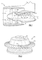
- an example integrally bladed rotor 50 includes a plurality of airfoils 52 extending radially away from a rotor hub.
- the example integrally bladed rotor 50 includes a damaged airfoil stub 56.
- the integrally bladed rotor 50 typically forms part of the low pressure compressor 18 and/or high pressure compressor 22 of the gas turbine engine 10.
- the integrally bladed rotor 50 is made of a titanium alloy, in this example, but may be made of nickel alloy or other materials.
- the damaged airfoil stub 56 is to be repaired.
- the integrally bladed rotor 50 is mounted within a linear friction welding machine incorporating a fixture 54.
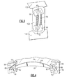
- the airfoil stub 56 is supported by a collar assembly 100.
- the collar 100 includes a sub-collar 64 associated with a leading edge 40 of the airfoil stub 56 and a sub-collar 68 associated with a trailing edge 41 of the airfoil stub 56.
- the sub-collars 64 and 68 each include a base portion 90 and a consumable portion 86.
- the consumable portion 86 is consumed during the linear friction welding.
- another example may include attaching an airfoil during initial assembly of the rotor 50.
- the example airfoil stub 56 includes a convex (or suction) side 74 and a concave (or pressure) side 78.
- the consumable portion 86 is defined by a surface 75 that is typically aligned with the convex side 74, and a surface 79 that is typically aligned with the concave side 78.
- the consumable portion 86 of the sub-collar 68 thus has a lateral profile that matches the geometry of an airfoil stub 56.
- a midline 82 of the consumable portion 86 and the portion of the airfoil stub 56 within the sub-collar 68 is centered between the surface 75 and the surface 79. That is, at a given chord position X, the distance D1 between the surface of the surface 75 and the midline 82 is the same as the distance D2 between the surface of the concave side surface 79 and the midline 82. In this example, the midline 82 is positioned between (or bounded by) the surface 74 and the surface 78.
- the consumable portion 86 is consumed while the base portion 90 remains.
- the sub-collars 64 and 68 are the same material as the airfoil stub 56 and the replacement airfoil 94 in this example. In another example, one or both of the sub-collars 64 and 68 is a different material than the airfoil stub 56, the replacement airfoil 94, or both.
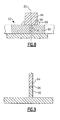
- a replacement airfoil 94 is positioned against the airfoil stub 56 and the consumable portion 86 of the sub-collar 64 at an interface 96.
- the replacement airfoil 94 oscillates back and forth in a weld direction D that is generally parallel to a chord of the airfoil stub 56.
- the consumable portion 86 and a portion of the airfoil stub 56 are consumed during the linear friction welding.
- the consumable portion 86 is sized such that the midline 82 is positioned between the surface 74 and the surface 78. This arrangement causes material in the consumable portion 86 to flow away from, rather than toward, the airfoil stub 56 as the material in the consumable portion 86 is consumed.
- the midline is radially extending relative to the engine axis X, in this example.
- the midline 82 represents the circumferential center of the section of the consumable portion 86 and the blade stub 56. That is, the midline is centered between the surface 74 and the surface 78, and the distance D1 is about the same as the distance D2.
- the consumable portion 86 includes substantially the same amount of material (within 5%, for example) on either side of the midline.
- the midline 82 is not centered between the surface 74 and the surface 78. However, in such examples, the midline still does not extend laterally past the surface 74 or the surface 78. Thus, it is possible that the distance D1 is not the same as the distance D2 After securing the airfoil 94 to the airfoil stub 56 and the consumable portion 86, the consumable portion 86 is machined away along with a portion of the replacement airfoil 94 and some of the airfoil stub 56.
- the disclosed examples include laterally balancing the amount of consumable material during a linear friction weld to avoid polluting desired welds with the material that would otherwise be expelled from the resultant linear friction weld joint.
- the consumable portion may contain more material on the concave side than on the convex side, or vice versa. Significantly more material on one of the sides could cause material intended for expulsion from the consumable portion to flow back toward the airfoil stub during the linear friction welding, which can pollute or otherwise foul the weld bond.
- the surface of the consumable portion of the collar in contact with the airfoil matches with the profile of the airfoil to provide intimate structural support during welding.
- the size of the airfoil is used to determine the size of the convex side of the collar and the size of the concave side of the collar resulting the flow of material away from the airfoil during the linear friction welding.
Landscapes
- Engineering & Computer Science (AREA)
- Mechanical Engineering (AREA)
- General Engineering & Computer Science (AREA)
- Ceramic Engineering (AREA)
- Pressure Welding/Diffusion-Bonding (AREA)
Applications Claiming Priority (1)
| Application Number | Priority Date | Filing Date | Title |
|---|---|---|---|
| US12/909,928 US9694440B2 (en) | 2010-10-22 | 2010-10-22 | Support collar geometry for linear friction welding |
Publications (2)
| Publication Number | Publication Date |
|---|---|
| EP2444192A2 true EP2444192A2 (de) | 2012-04-25 |
| EP2444192A3 EP2444192A3 (de) | 2015-04-01 |
Family
ID=44862626
Family Applications (1)
| Application Number | Title | Priority Date | Filing Date |
|---|---|---|---|
| EP11186120.9A Withdrawn EP2444192A3 (de) | 2010-10-22 | 2011-10-21 | Stützbandgeometrie für lineares Reibschweißen |
Country Status (3)
| Country | Link |
|---|---|
| US (1) | US9694440B2 (de) |
| EP (1) | EP2444192A3 (de) |
| SG (1) | SG180088A1 (de) |
Cited By (6)
| Publication number | Priority date | Publication date | Assignee | Title |
|---|---|---|---|---|
| WO2014130149A1 (en) * | 2013-02-25 | 2014-08-28 | Rolls-Royce Corporation | Disk and blade stalk bounded by motion weld and methods for motion welding |
| CN104822483A (zh) * | 2012-11-28 | 2015-08-05 | 斯奈克玛 | 用于摩擦焊接叶片到涡轮发动机转子盘上的方法;相应的一体的叶片盘 |
| US20160076376A1 (en) * | 2014-09-16 | 2016-03-17 | Rolls-Royce Plc | Method of replacing damaged aerofoil |
| US20170314401A1 (en) * | 2016-04-27 | 2017-11-02 | MTU Aero Engines AG | Method for producing a blade for a turbomachine |
| US10384302B2 (en) * | 2017-02-24 | 2019-08-20 | Rolls-Royce Plc | Weld stub arrangement and a method of using the arrangement to make an article |
| EP3808936A1 (de) * | 2019-10-18 | 2021-04-21 | Raytheon Technologies Corporation | Verfahren zur wartung eines gasturbinenmotors oder von komponenten |
Families Citing this family (4)
| Publication number | Priority date | Publication date | Assignee | Title |
|---|---|---|---|---|
| US9551230B2 (en) * | 2015-02-13 | 2017-01-24 | United Technologies Corporation | Friction welding rotor blades to a rotor disk |
| GB201519805D0 (en) * | 2015-11-10 | 2015-12-23 | Rolls Royce Plc | Rotary friction welding |
| US10260362B2 (en) * | 2017-05-30 | 2019-04-16 | Rolls-Royce Corporation | Turbine vane assembly with ceramic matrix composite airfoil and friction fit metallic attachment features |
| BE1031531B1 (fr) * | 2023-04-21 | 2024-11-28 | Safran Aero Boosters | Procédé de dimensionnement de moignons d'un disque aubagé de turbomachine destinés au soudage orbital |
Family Cites Families (37)
| Publication number | Priority date | Publication date | Assignee | Title |
|---|---|---|---|---|
| DE1963546C3 (de) | 1969-12-18 | 1974-03-07 | Steigerwald, Karl-Heinz, Dipl.Phys., 8130 Starnberg | Verfahren und Vorrichtung zum Reibungsschweißen |
| AT302789B (de) | 1970-04-07 | 1972-10-25 | Evg Entwicklung Verwert Ges | Verfahren und Maschine zum Herstellen von geschweißten Gittern nach der Reibschweißmethode |
| US4462849A (en) | 1982-04-23 | 1984-07-31 | Cosden Technology, Inc. | Method of oscillatory bonding |
| US4515651A (en) | 1982-04-23 | 1985-05-07 | Vercon Inc. | Apparatus for oscillatory bonding of dissimilar thermoplastic materials |
| US4934583A (en) * | 1988-03-28 | 1990-06-19 | General Electric Company | Apparatus for bonding an article projection |
| US4883216A (en) | 1988-03-28 | 1989-11-28 | General Electric Company | Method for bonding an article projection |
| US4873751A (en) | 1988-12-27 | 1989-10-17 | United Technologies Corporation | Fabrication or repair technique for integrally bladed rotor assembly |
| GB8914273D0 (en) | 1989-06-21 | 1989-08-09 | Rolls Royce Plc | Friction bonding apparatus |
| GB2237758B (en) | 1989-11-07 | 1992-10-21 | Rolls Royce Plc | Rotor assembly and method of manufacture |
| US5188275A (en) | 1990-05-24 | 1993-02-23 | Rolls-Royce Plc | Friction bonding clamp for a rotor blade |
| DE4023816A1 (de) | 1990-07-27 | 1992-02-06 | Deutsche Forsch Luft Raumfahrt | Thermomechanisches verfahren zur behandlung von titanaluminiden auf der basis ti(pfeil abwaerts)3(pfeil abwaerts)al |
| US5489194A (en) | 1990-09-14 | 1996-02-06 | Hitachi, Ltd. | Gas turbine, gas turbine blade used therefor and manufacturing method for gas turbine blade |
| US5109606A (en) | 1991-03-04 | 1992-05-05 | United Technologies Corporation | Integrally bladed rotor fabrication or repair |
| US5197190A (en) | 1991-03-04 | 1993-03-30 | United Technologies Corporation | Fabrication of repair method for an integrally bladed rotor |
| GB2257340B (en) | 1991-06-25 | 1995-05-10 | Turbine Blading Ltd | Heat treatment apparatus and methods of repair of turbine blades |
| US5484983A (en) | 1991-09-11 | 1996-01-16 | Tecnit-Techische Textilien Und Systeme Gmbh | Electric heating element in knitted fabric |
| US5248077A (en) | 1992-11-03 | 1993-09-28 | Extrude Hone Corporation | Friction welding and welds made by friction |
| DE69404738T2 (de) | 1993-05-13 | 1998-02-19 | Rolls Royce Plc | Reibschweissen |
| GB9309822D0 (en) | 1993-05-13 | 1993-06-23 | Allwood Searle & Timney | Improvements relating to friction welding |
| GB9309819D0 (en) | 1993-05-13 | 1993-06-23 | Allwood Searle & Timney | Imprivements relating to friction welding |
| FR2716397B1 (fr) | 1994-02-23 | 1996-04-05 | Snecma | Procédé de soudage de deux parties d'aube. |
| US5609471A (en) | 1995-12-07 | 1997-03-11 | Allison Advanced Development Company, Inc. | Multiproperty rotor disk and method of manufacture |
| US5611479A (en) | 1996-02-20 | 1997-03-18 | Rockwell International Corporation | Friction stir welding total penetration technique |
| US5755031A (en) * | 1996-11-12 | 1998-05-26 | United Technologies Corporation | Method for attaching a rotor blade to an integrally bladed rotor |
| US5813593A (en) * | 1996-11-15 | 1998-09-29 | General Electric Company | Translational friction welding apparatus and method |
| GB2320451A (en) | 1996-12-20 | 1998-06-24 | Rolls Royce Plc | Friction welding apparatus |
| US5865364A (en) * | 1996-12-24 | 1999-02-02 | United Technologies Corporation | Process for linear friction welding |
| US6478545B2 (en) * | 2001-03-07 | 2002-11-12 | General Electric Company | Fluted blisk |
| US6536110B2 (en) | 2001-04-17 | 2003-03-25 | United Technologies Corporation | Integrally bladed rotor airfoil fabrication and repair techniques |
| US6688512B2 (en) | 2001-12-20 | 2004-02-10 | United Technologies Corporation | Apparatus and method for friction welding |
| US6598489B1 (en) | 2002-03-29 | 2003-07-29 | Micro Motion, Inc. | Balance bar having a reduced axial thermal stress resulting from high temperature manufacturing methods |
| US8516674B2 (en) * | 2003-11-14 | 2013-08-27 | General Electric Company | Solid state resistance welding for airfoil repair and manufacture |
| GB0412775D0 (en) * | 2004-06-09 | 2004-07-07 | Rolls Royce Plc | Method of replacing damaged aerofoil |
| US20080235946A1 (en) | 2007-03-29 | 2008-10-02 | Yamashita Rubber Kabushiki Kaisha | Link rod manufacturing method |
| DE102008017495B8 (de) | 2008-04-04 | 2015-01-15 | Rolls-Royce Deutschland Ltd & Co Kg | Verfahren zur Herstellung oder Reparatur von integral beschaufelten Rotoren |
| DE102008057160A1 (de) * | 2008-11-13 | 2010-05-20 | Mtu Aero Engines Gmbh | Verfahren zum Austausch eines inneren Scheibenelements einer integral beschaufelten Scheibe |
| DE102009033835B4 (de) * | 2009-07-18 | 2012-01-19 | Mtu Aero Engines Gmbh | Verfahren zum Austauschen einer Schaufel eines Rotors mit integrierter Beschaufelung und ein derartiger Rotor |
-
2010
- 2010-10-22 US US12/909,928 patent/US9694440B2/en active Active
-
2011
- 2011-10-05 SG SG2011072790A patent/SG180088A1/en unknown
- 2011-10-21 EP EP11186120.9A patent/EP2444192A3/de not_active Withdrawn
Non-Patent Citations (1)
| Title |
|---|
| None |
Cited By (11)
| Publication number | Priority date | Publication date | Assignee | Title |
|---|---|---|---|---|
| CN104822483A (zh) * | 2012-11-28 | 2015-08-05 | 斯奈克玛 | 用于摩擦焊接叶片到涡轮发动机转子盘上的方法;相应的一体的叶片盘 |
| CN104822483B (zh) * | 2012-11-28 | 2017-04-26 | 斯奈克玛 | 用于摩擦焊接叶片到涡轮发动机转子盘上的方法及其用于制造或修复叶盘的用途 |
| WO2014130149A1 (en) * | 2013-02-25 | 2014-08-28 | Rolls-Royce Corporation | Disk and blade stalk bounded by motion weld and methods for motion welding |
| US9896948B2 (en) | 2013-02-25 | 2018-02-20 | Rolls-Royce Corporation | Gas turbine engine blade and disk |
| US20160076376A1 (en) * | 2014-09-16 | 2016-03-17 | Rolls-Royce Plc | Method of replacing damaged aerofoil |
| US9500080B2 (en) * | 2014-09-16 | 2016-11-22 | Rolls-Royce Plc | Method of replacing damaged aerofoil |
| US20170314401A1 (en) * | 2016-04-27 | 2017-11-02 | MTU Aero Engines AG | Method for producing a blade for a turbomachine |
| US10526902B2 (en) * | 2016-04-27 | 2020-01-07 | MTU Aero Engines AG | Method for producing a blade for a turbomachine |
| US10384302B2 (en) * | 2017-02-24 | 2019-08-20 | Rolls-Royce Plc | Weld stub arrangement and a method of using the arrangement to make an article |
| EP3808936A1 (de) * | 2019-10-18 | 2021-04-21 | Raytheon Technologies Corporation | Verfahren zur wartung eines gasturbinenmotors oder von komponenten |
| US11725516B2 (en) | 2019-10-18 | 2023-08-15 | Raytheon Technologies Corporation | Method of servicing a gas turbine engine or components |
Also Published As
| Publication number | Publication date |
|---|---|
| SG180088A1 (en) | 2012-05-30 |
| US9694440B2 (en) | 2017-07-04 |
| EP2444192A3 (de) | 2015-04-01 |
| US20120099998A1 (en) | 2012-04-26 |
Similar Documents
| Publication | Publication Date | Title |
|---|---|---|
| US9694440B2 (en) | Support collar geometry for linear friction welding | |
| CN103084780B (zh) | 用于维修涡轮叶片顶部的方法 | |
| EP3115147A1 (de) | Systeme und verfahren zur reparatur von turbinenschaufeln | |
| CN110131209B (zh) | 带有叶片的涡轮发动机 | |
| EP1657405B1 (de) | Leitschaufelanordnung für eine Gasturbine | |
| EP1967693A2 (de) | Teilerverkleidungsreparatur | |
| CN101311497B (zh) | 在带冠涡轮机叶片上中心定位切齿的方法 | |
| US8479391B2 (en) | Consumable collar for linear friction welding of blade replacement for damaged integrally bladed rotors | |
| US20170167263A1 (en) | Systems and methods for deep tip crack repair | |
| US8177502B2 (en) | Vane with reduced stress | |
| US12497898B2 (en) | Turbine blade tip shroud with axially offset cutter teeth, and related surface profiles and method | |
| JP2013256961A (ja) | ロータブレード | |
| US9567860B2 (en) | Fixture for an airfoil shroud and method for modifying an airfoil shroud | |
| JP2005201242A (ja) | ガスタービンロータブレードを修理する方法 | |
| EP2735704A2 (de) | Verfahren zur Modifizierung eines Schaufeldeckbandes und Schaufel | |
| EP2189662A2 (de) | Schaufel mit reduzierter Spannung | |
| US20100126018A1 (en) | Method of manufacturing a vane with reduced stress | |
| US9828857B2 (en) | Repaired or remanufactured blade platform for a gas turbine engine | |
| CN208106502U (zh) | 叶片及涡轮机 | |
| NL2002340C2 (en) | Method for repairing a cooled turbine nozzle segment. | |
| US20160362988A1 (en) | Method for modifying an airfoil shroud and airfoil | |
| US20170198584A1 (en) | Systems and methods for repairing a component of a rotary machine | |
| US20140147284A1 (en) | Method for modifying an airfoil shroud |
Legal Events
| Date | Code | Title | Description |
|---|---|---|---|
| AK | Designated contracting states |
Kind code of ref document: A2 Designated state(s): AL AT BE BG CH CY CZ DE DK EE ES FI FR GB GR HR HU IE IS IT LI LT LU LV MC MK MT NL NO PL PT RO RS SE SI SK SM TR |
|
| AX | Request for extension of the european patent |
Extension state: BA ME |
|
| PUAI | Public reference made under article 153(3) epc to a published international application that has entered the european phase |
Free format text: ORIGINAL CODE: 0009012 |
|
| PUAL | Search report despatched |
Free format text: ORIGINAL CODE: 0009013 |
|
| AK | Designated contracting states |
Kind code of ref document: A3 Designated state(s): AL AT BE BG CH CY CZ DE DK EE ES FI FR GB GR HR HU IE IS IT LI LT LU LV MC MK MT NL NO PL PT RO RS SE SI SK SM TR |
|
| AX | Request for extension of the european patent |
Extension state: BA ME |
|
| RIC1 | Information provided on ipc code assigned before grant |
Ipc: B23K 20/12 20060101AFI20150224BHEP Ipc: F01D 25/28 20060101ALI20150224BHEP Ipc: F01D 5/34 20060101ALI20150224BHEP |
|
| 17P | Request for examination filed |
Effective date: 20150930 |
|
| RBV | Designated contracting states (corrected) |
Designated state(s): AL AT BE BG CH CY CZ DE DK EE ES FI FR GB GR HR HU IE IS IT LI LT LU LV MC MK MT NL NO PL PT RO RS SE SI SK SM TR |
|
| 17Q | First examination report despatched |
Effective date: 20160407 |
|
| RAP1 | Party data changed (applicant data changed or rights of an application transferred) |
Owner name: UNITED TECHNOLOGIES CORPORATION |
|
| STAA | Information on the status of an ep patent application or granted ep patent |
Free format text: STATUS: THE APPLICATION HAS BEEN WITHDRAWN |
|
| 18W | Application withdrawn |
Effective date: 20170612 |