EP2444206B1 - Outil de travail - Google Patents
Outil de travail Download PDFInfo
- Publication number
- EP2444206B1 EP2444206B1 EP10789527.8A EP10789527A EP2444206B1 EP 2444206 B1 EP2444206 B1 EP 2444206B1 EP 10789527 A EP10789527 A EP 10789527A EP 2444206 B1 EP2444206 B1 EP 2444206B1
- Authority
- EP
- European Patent Office
- Prior art keywords
- housing
- motor
- air
- cylindrical portion
- power tool
- Prior art date
- Legal status (The legal status is an assumption and is not a legal conclusion. Google has not performed a legal analysis and makes no representation as to the accuracy of the status listed.)
- Active
Links
Images
Classifications
-
- B—PERFORMING OPERATIONS; TRANSPORTING
- B25—HAND TOOLS; PORTABLE POWER-DRIVEN TOOLS; MANIPULATORS
- B25F—COMBINATION OR MULTI-PURPOSE TOOLS NOT OTHERWISE PROVIDED FOR; DETAILS OR COMPONENTS OF PORTABLE POWER-DRIVEN TOOLS NOT PARTICULARLY RELATED TO THE OPERATIONS PERFORMED AND NOT OTHERWISE PROVIDED FOR
- B25F5/00—Details or components of portable power-driven tools not particularly related to the operations performed and not otherwise provided for
- B25F5/006—Vibration damping means
-
- B—PERFORMING OPERATIONS; TRANSPORTING
- B25—HAND TOOLS; PORTABLE POWER-DRIVEN TOOLS; MANIPULATORS
- B25D—PERCUSSIVE TOOLS
- B25D17/00—Details of, or accessories for, portable power-driven percussive tools
- B25D17/20—Devices for cleaning or cooling tool or work
-
- B—PERFORMING OPERATIONS; TRANSPORTING
- B25—HAND TOOLS; PORTABLE POWER-DRIVEN TOOLS; MANIPULATORS
- B25D—PERCUSSIVE TOOLS
- B25D17/00—Details of, or accessories for, portable power-driven percussive tools
- B25D17/24—Damping the reaction force
-
- B—PERFORMING OPERATIONS; TRANSPORTING
- B25—HAND TOOLS; PORTABLE POWER-DRIVEN TOOLS; MANIPULATORS
- B25D—PERCUSSIVE TOOLS
- B25D2211/00—Details of portable percussive tools with electromotor or other motor drive
- B25D2211/06—Means for driving the impulse member
- B25D2211/061—Swash-plate actuated impulse-driving mechanisms
-
- B—PERFORMING OPERATIONS; TRANSPORTING
- B25—HAND TOOLS; PORTABLE POWER-DRIVEN TOOLS; MANIPULATORS
- B25D—PERCUSSIVE TOOLS
- B25D2217/00—Details of, or accessories for, portable power-driven percussive tools
- B25D2217/0057—Details related to cleaning or cooling the tool or workpiece
- B25D2217/0061—Details related to cleaning or cooling the tool or workpiece related to cooling
-
- B—PERFORMING OPERATIONS; TRANSPORTING
- B25—HAND TOOLS; PORTABLE POWER-DRIVEN TOOLS; MANIPULATORS
- B25D—PERCUSSIVE TOOLS
- B25D2222/00—Materials of the tool or the workpiece
- B25D2222/54—Plastics
- B25D2222/57—Elastomers, e.g. rubber
-
- B—PERFORMING OPERATIONS; TRANSPORTING
- B25—HAND TOOLS; PORTABLE POWER-DRIVEN TOOLS; MANIPULATORS
- B25D—PERCUSSIVE TOOLS
- B25D2250/00—General details of portable percussive tools; Components used in portable percussive tools
- B25D2250/121—Housing details
-
- B—PERFORMING OPERATIONS; TRANSPORTING
- B25—HAND TOOLS; PORTABLE POWER-DRIVEN TOOLS; MANIPULATORS
- B25D—PERCUSSIVE TOOLS
- B25D2250/00—General details of portable percussive tools; Components used in portable percussive tools
- B25D2250/371—Use of springs
Definitions
- the invention relates to a technique to reduce a vibration of a power tool which performs a predetermined operation by using a tool driven by a motor.
- EP 1 832 395 A1 discloses a disc grinder comprising a vibration reducing mechanism.
- DE 10 2005 016 453 A1 discloses a power tool comprising a vibration reducing mechanism.
- DE 42 11 316 A1 discloses a housing for a power tool.
- Japanese Examined Utility Model Application Publication No. H01-018306 discloses a vibration reducing mechanism of an electric hammer.
- the electric hammer connects a handle to a body via an elastic rubber to reduce transmission of vibration occurred on the body to the handle, when the electric hammer is driven.
- An object is, in consideration of the above described problem, to provide a technique which further improves a vibration reducing effect of a power tool.
- a representative power tool is provided to perform a predetermined operation by using a tool driven by a motor.
- the power tool including: a first housing to which the tool is attached at an end of the first housing and which has a first cylindrical portion at the other end; a second housing which has a second cylindrical portion covering the first cylindrical portion, wherein the second cylindrical portion is adapted relatively movable to the first cylindrical portion; and a vibration reduction member which is provided between the first cylindrical portion and the second cylindrical portion and which reduces transmission of vibration between the first housing and the second housing via elastic shearing deformation of the vibration reduction member. Then, a direction of the shearing deformation of the vibration reduction member corresponds to a direction of a rotation axis of the motor. Further, typically the motor is preferable entirely or partially housed in the first housing.
- the power tool preferably includes that typically not only a hammer tool, such as a hammer which performs a hammer operation to a workpiece by making a hammer bit as a tool a hammering action along a longitudinal direction of the hammer bit or a hammer drill which performs a hammer-drill operation to a workpiece by making a hammer bit a hammering action and a drill action or like this, but also, aside from the hammer tool, a disk grinder or a disk sander which performs a grind operation to a workpiece by making a grinding wheel or a sanding wheel as a tool a grind action.
- a hammer tool such as a hammer which performs a hammer operation to a workpiece by making a hammer bit as a tool hammering action along a longitudinal direction of the hammer bit or a hammer drill which performs a hammer-drill operation to a
- the first housing typically corresponds to a housing which houses a motor, a driving mechanism which drives the tool by transmitting rotation force of the motor and so on
- the second housing corresponds to a handle which is held by a user to operate the power tool.
- the vibration reduction member typically corresponds to a rubber.
- the power tool when the power tool is in an operation, transmission of vibration between the first housing and the second housing via a damping effect of a shearing deformation of the vibration reduction member is reduced.
- a shearing stiffness of the vibration reduction member is lower than an axial stiffness. That is, by utilizing a feature which an effect of reducing vibration via the shearing deformation is higher than an effect of reducing vibration via the axial deformation, according to the power tool having the second cylindrical portion which covers the first cylindrical portion, the power tool is arranged and adapted to reduce transmission of vibration between the first housing and the second housing via the damping effect of the shearing deformation, in this way, an effect of reducing vibration is further improved.
- a cooling air passage is formed by means of a gap between the first cylindrical portion and the second cylindrical portion, wherein the vibration reduction member is located at the cooling air passage and cooled by an air flowing through the cooling air passage, which flowed by means of a cooling motor fan to cool the motor, wherein the cooling motor fan is housed in the first housing together with the motor.
- a rubber as a vibration reduction member has both effects of reducing vibration by means of spring action and damping action. In damping action, vibration is changed into heat so that the rubber itself adversely generates heat.
- the vibration reduction member when the rubber is utilized as the vibration reduction member, because the vibration reduction member is located at the cooling air passage and is cooled by means of a cooling air forcibly flowed by the cooling motor fan, thermal degradation is reduced and endurance of the vibration reduction member is improved.
- the first cylindrical portion is covered by the second cylindrical portion, the gap of both of housings is rationally useful as the cooling air passage.
- the second housing has a grip portion held by a user of the power tool, wherein the grip portion extends in a direction crossing a longitudinal direction of the second housing from one end of the second cylindrical portion opposite to the end where the tool is attached and wherein a distal end of the grip portion is defined as a free end.
- the cooling motor fan is provided closer to the tool than the motor, and the vibration reduction member is provided between the motor and the cooling motor fan.
- the grip portion is also called a pistol-formed grip, which the grip portion extends in a direction crossing a longitudinal direction of the second housing from the one end of the second cylindrical portion and the distal end of the grip portion is defined as a free end.
- the grip portion when the power tool performs an operation to a workpiece, aside from gripping the grip portion by a hand and fingers, there is other way of gripping the grip portion by putting a palm on an end (rear end) which is in vicinity of a connection area of the cylindrical portion and the grip portion, and putting fingers on side surface of the cylindrical portion, in the latter way of gripping, tip of the fingers extend forward along the side surface of the cylindrical portion, that is, the tip of fingers extend toward a side of the tool attached.
- a part of the second housing corresponding to where the vibration reduction member is provided may protrude toward outside, when a protruding part exists, because the tip of fingers may touch the protruding part by means of the latter way of gripping the grip portion, easiness of gripping performance may be harmed.
- the vibration reduction member is provided between the motor and the cooling motor fan described above, that is, the vibration reduction member is provided more forward than the motor.
- a length between an end of the grip portion opposed to the tool and the protruding part is set to at least a length corresponding to a length of a motor shaft. Accordingly, harming easiness of gripping grip by means of the latter way of gripping the grip portion is avoided.
- the power tool further comprising; an air inlet which leads an air from outside to the cooling air passage, and an air outlet which exhausts the air to outside wherein the motor is cooled by the air, wherein the air outlet is provided closer to the tool than the air inlet.
- the air outlet of the aspect is typically defined by a singular slit or plurality of slits which extends for a predetermined length along a circumference direction or a longitudinal direction of a housing, and provided at the first housing.
- the air inlet is typically provided at a front side of the second cylindrical portion which covers the first housing.
- the dust may be carried into the cooling air passage by the air led from the air inlet.
- the air inlet is located backward with respect to the air outlet so that a protection wall (air barrier) is formed by flowing air exhausted from the air outlet, in this way, the dust and things like that are prevented from entering into the air inlet and the motor and so on provided in the housing are protected against the dust.
- a distance between the air outlet and the air inlet may be decided accordingly to get an effect of dust protection with respect to the air inlet by taking into consideration about amount of the air, strength (velocity) of the air and so on exhausted from the air outlet.
- the air outlet and the air inlet are arranged in conformity with each other with respect to a circumference direction of the first housing. Further, the air outlet and the air inlet may be arranged at a region where an air flow exhausted from the air outlet hardly gives bad effect to a user holding the power tool, that is, if the power tool is adapted for a right-hander, the region corresponds to a right side surface or an under surface of the first housing or the second housing.
- the air inlet has a dust prevention portion to prevent dust from entering into the air inlet.
- the dust prevention portion is preferably adapted by a labyrinth seal or an air filter and so on. Accordingly, dust is prevented from entering from the air inlet and the motor and so on provided in the housing are protected against the dust.
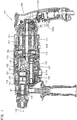
- a hammer drill 101 of this embodiment is provided mainly with a body 103 which forms an outer shell of the power tool 101, a hammer bit 119 which is detachably attached to a front side (a left side of Fig. 1 ) of the body 103 via a tool holder 137, and a handle 109 which connects to the body 103 opposed to the hammer bit 119.
- the body 103 corresponds to a first housing.
- the handle 109 corresponds to a second housing.
- the hammer bit 119 corresponds to a tool.
- the body 103 is provided mainly with a motor housing 105 which houses a driving motor 111, and a gear housing 107 which houses a motion conversion mechanism 113, a hammering element 115 and a power transmission mechanism 117.
- the driving motor 111 corresponds to a motor.
- the motion conversion mechanism 113, the hammering element 115 and the power transmission mechanism 117 define a driving mechanism.
- the driving motor 111 is provided as a rotational axis of the driving motor 111 is arranged in parallel with a longitudinal direction of the body 103 (a longitudinal direction of the hammer bit 119). That is, a direction of the rotational axis of the driving motor 111 is arranged in conformity with a direction of the hammer bit 119 to hammer.
- a rotation output of the driving motor 111 is converted as needed to a linear motion by the motion conversion mechanism 113, and then transmitted to the hammering element 115, therefore the rotation output makes an impact force via the hammering element 115 along the longitudinal direction (a lateral direction in Fig. 1 ) of the hammer bit 119.
- the rotation output of the driving motor 111 is decelerated as needed by the motion transmission mechanism 117, and then transmitted to the hammer bit 119, therefore the hammer bit 119 rotates in a circumference direction.
- the driving motor 111 is turned on and driven by pulling a trigger 109a which is provided on the handle 109.
- a side where the hammer bit 119 is provided is called front and the other side where the handle 109 is provided is called rear.
- the motion conversion mechanism 113 is provide mainly with an intermediate shaft 125 which is rotated by the driving motor 111, a swinging ring 129 which is defined as a swinging member swung along the longitudinal direction of the hammer bit 119 accompanied by a rotation of the intermediate shaft 125 via a rotating member 127, and a cylindrical piston 131 which moves linearly along the longitudinal direction of the hammer bit 119 with a swing of the swing ring 129.
- the power transmission mechanism 117 is provided mainly with a decelerating gear mechanism which is defined by a plurality of gears such as a small diameter gear 133 which rotates at unity with the intermediate shaft 125, and a large diameter gear 135 which engages with the small diameter gear 133, and so on. Therefore the power transmission mechanism 117 transmits torque to the tool holder 137. In this way, the tool holder 137 rotates in a vertical plane, with accompanying a rotation of the tool holder 137, the hammer bit 119 rotates which is held by the tool holder 137. Concerning compositions of the power conversion mechanism 113 and the power transmission mechanism 117, the compositions are well known, therefore a detail description of those compositions is omitted.
- the hammering element 115 is provided mainly with a striker 143 as a hammer element which is slidably arranged in a cylindrical piston 131, and an impact bolt 145 as an intermediate element which is slidably arranged against the tool holder 137.
- the striker 143 is moved via an air spring (pressure fluctuation) of an air space 131a accompanied with a sliding motion of the cylindrical piston 131, and the striker 143 impacts (hammers) the impact bolt 145, therefore an impact force is transmitted to the hammer bit 119 via the impact bolt 145.
- the rotation output is transmitted as the linear motion to the hammer bit 119 in the longitudinal direction of the hammer bit 119 via the hammering element 115. That is, the hammer bit 119 performs a hammering action.
- the rotation is transmitted to the hammer bit 119 via the motion transmission mechanism 117 driven by the rotation output of the driving motor 111, therefore the hammer bit 119 performs a rotation action in a circumference direction. That is, the hammer bit 119 acts the hammering action along the longitudinal direction and the rotation action in the circumference direction, therefore the hammer bit 119 performs a hammer-drill operation to a workpiece.
- the hammer drill 101 has a dial to change modes of operation to perform. By a user operates the dial as needed, the modes may be changed between a drill mode which the hammer drill 101 performs a drill operation to the workpiece by giving the hammer bit 119 the impact force in the longitudinal direction and the rotation in the circumference direction, and a hammer-drill mode which the hammer drill 101 performs the hammer-drill operation to the workpiece by giving the hammer bit 119 only the rotation in the circumference direction. Because a mode changing mechanism mentioned above is well known and is not directly concerned with the invitation, a detail description of the mode changing mechanism is omitted.
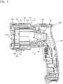
- the handle 109 has a cylindrical housing portion 151 formed approximately as a cylinder which has an opening toward the front, and a grip portion 153 held by a user which is fixed to a rear end of the cylindrical housing portion 151 via a plurality of screws.
- the cylindrical housing portion 151 of the grip 109 covers over almost all regions except a region of a front part within the motor housing 105 formed approximately as a cylinder.
- the cylindrical housing portion 151 corresponds to a second cylindrical portion
- the motor housing 105 corresponds to a first cylindrical portion.
- the motor housing 105 is formed as a cylindrical member which extends in parallel with the longitudinal direction of the hammer bit 119, and houses the driving motor 111 and a cooling motor fan 112 which is driven by the driving motor 111 (refer to Fig. 1 ).
- the cooling motor fan 112 is arranged forward against the driving motor 111.
- the grip portion 153 of the handle 109 is formed as a rod-shaped member which extends in a direction (down ward) crossing a longitudinal direction of the cylindrical housing portion 151 (the longitudinal direction of the hammer bit 119) from a rear end of the cylindrical housing portion 151 and a distal end of the grip portion 153 is defined as a free end.
- the handle 109 having the grip portion 153 described above is called generally a pistol-shaped handle.
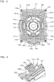
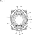
- a plurality of elastic rubbers 155 in this embodiment, four elastic rubbers 155 to reduce vibration are arranged between an outside surface of the motor housing 105 and an inside surface of the cylindrical housing portion 151 of the handle 109 which covers the motor housing 105, and each of the four elastic rubbers 155 is arranged at certain interval around the rotational axis of the driving motor 111 (along a circumference direction of the cylindrical housing portion 151). That is, the cylindrical housing portion 151 is relatively movable to the motor housing 105 and connects the motor housing 105 via the four elastic rubbers 155 arranged around the rotational axis of the driving motor 111.
- the elastic rubber 155 corresponds to a vibration reduction member.
- the four elastic rubbers 155 are arranged symmetry with respect to a vertical line crossing the rotational axis of the driving motor 111.
- Each of the elastic rubbers 155 is clamped by an outside rubber receiving portion 151a which has a semispherical depressed surface formed on the cylindrical housing portion 151, and an inside rubber receiving portion 105a which has a semispherical depressed surface formed on the motor housing 105.
- the outside rubber receiving portion 151a of the cylindrical housing portion 151 consists of the cylindrical housing portion 151 and the a ring-shaped cover 152 fixed in front of the cylindrical housing portion 151 via a plurality of screws 156.
- the outside rubber receiving portion 151a is formed across both of divided the housing portion and the cover portion. Therefore, the elastic rubber 155 is assembled between the motor housing 105 and the cylindrical housing portion 151.
- facing surfaces of the outside rubber receiving portion 151a and the inside rubber receiving portion 105a facing each other in each parts forms approximately inversed V-formation when viewed from a side of the handle 109 (a rear side).
- facing surfaces of the outside rubber receiving portion 151a and the inside rubber receiving portion 105a facing each other in each parts forms approximately V-formation when viewed from the side of the handle 109.
- the facing surfaces of the outside rubber receiving portion 151a and the inside rubber receiving portion 105a are arranged in parallel with the longitudinal direction of the hammer bit 119 and inclined at an angle of approximately 45 degrees with respect to horizontal direction (a direction of right and left) and vertical direction (a direction of top and bottom) crossing the longitudinal direction respectively.
- shearing force acts on each of the elastic rubbers 155 mainly in the longitudinal direction
- axial compression force acts on each of the elastic rubbers 155 mainly in a direction crossing the longitudinal direction.
- the ring-shaped gap is formed between the inside surface of the cylindrical housing portion 151 (including an inside surface of the cover 152) and the outside surface of the motor housing 105 connected each other via the elastic rubber 155, and the elastic rubber 155 is provide at the gap.
- the gap forms a cooling air passage 157 to cool the driving motor 111, and further the driving motor 111 and the elastic rubber 155 are cooled by an air flowing through the cooling air passage 157 flowed forcibly by means of the cooling motor fan 112.
- the motor housing 105 has an air inlet 159 which leads an air from outside into a front side of the cooling air passage 157.
- the air outlet 163 is provided more forward than the air inlet 159, and the air outlet 163 is arranged at right side and underside surface totally two points of the motor housing 105, when viewed from the side of the handle (for convenience, only the air inlet 163 arranged at right side is shown).
- the hammer drill 101 is intended to a right-handed user who grips the grip portion 153 of the handle 109 by right hand of the user, therefore a location of the air outlet 163 is defined at where the air which is exhausted from the air outlet 153 does not give a bad effect to the user.
- the air outlet 153 is composed of a slit (pore) which extends in the circumference direction of the motor housing 105.
- the air inlet 159 is arranged at right side and underside surface totally two points of the motor housing 105 corresponding to the air outlet 163. That is, the air inlet 159 is provided in conformity with the air outlet 163 with respect to the circumference direction of the motor housing 105.
- the motor housing 105 has cover portions 165 at right side and underside surface of the motor housing 105, which protrude toward rear side from where the motor housing 105 is not covered by the cylindrical housing portion 151 respectively.
- the cover portion 165 extends toward the rear side along an outside surface of the cylindrical housing portion 151, therefore the air inlet 159 is formed between an inside surface of the cover portion 165 and the outside surface of the cylindrical housing portion 151, and the air inlet 159 is only opened toward the rear side. That is, the air inlet 159, is defined as an inner space through which the outside air flows, after the outside air inflows from an opening of the rear side of the cover portion 165, the outside air changes the direction of flowing at the inner part (the front side) of the cover portion 165 and flows into the cooling air passage 157. In this way, the air inlet 159 has a labyrinth seal composed of a passage formed U-formation.
- the region is formed as a tightened passage arranged between the outside surface of the cylindrical housing portion 151 and the inside surface of the motor housing 105, or the region has a seal portion on the cover 152 which seals a gap, therefore dust is hardly allowed to enter from the air inlet 159.
- a slide guide 167 which guides the cylindrical housing portion 167 is provided.
- the slide guide 167 is provided together with the motor housing 105 in some region with respect to the longitudinal direction of the motor housing 105, an outside surface of the slide guide 167 slidably contacts to the inside surface of the cylindrical housing portion 151, therefore the cylindrical housing portion 151 is relatively movable in the longitudinal direction steadily with respect to the motor housing 105.
- the hammer drill 101 is comprised described above. Accordingly, when the hammer drill 101 is in an operation, impactive and cyclic vibration along the longitudinal direction of the hammer bit 119 is occurred on the body 103, but transmission of the vibration from the motor housing 105 which is a component of the body 103 to the cylindrical housing portion 151 which is a component of the handle 109 is restricted by means of an elastic deformation of the elastic rubber 155.
- the spherical elastic rubber 155 is held by fitting in a spherical depressed surface of the inside rubber receiving portion 105a and a spherical depressed surface of the outside rubber receiving portion 151a. In this way, the elastic rubber 155 deforms in shearing direction due to the vibration described above.
- the cylindrical housing portion 151 of the handle 109 is guided in the longitudinal direction of the hammer bit 119 by the slide guide 167 provided on the motor housing 105. Therefore, when added a pushing power in the longitudinal direction onto the body 103 of the hammer drill 101 to perform a operation, a pushing operation against the workpiece is performed under stable condition.
- a vibration reducing handle is provided by arranging the cylindrical housing portion 151 of the handle 109 on which the cylindrical housing portion 151 covers the motor housing 105 via the elastic rubber 155, and the gap between the motor housing 105 and the cylindrical housing portion 151 is defined as the cooling air passage 157 through which an air flows forcibly by means of the cooling motor fan 112, therefore the elastic rubber 155 is actively cooled.
- the elastic rubber 155 When the elastic rubber 155 reduces the vibration by means of its damping effect, the vibration is changed into heat so that the elastic rubber 155 itself adversely generates heat, but according to this embodiment, the elastic rubber 155 located at the cooling air passage 157 is cooled by the air flowing through the cooling air passage 157, therefore it is possible thermal degradation of the elastic rubber 155 is reduced and endurance of the elastic rubber 155 is improved.
- the gap between the motor housing 105 and cylindrical housing portion 151 is defined as the cooling air passage 157 of flowing air, so that a ready-made air inlet may be eliminated or reduced, and greater design flexibility is offered.
- the elastic rubber 155 is provided between the motor housing 105 and the cylindrical housing portion 151 covering the motor housing 105, as shown in Fig. 3 and Fig. 4 , concerning the cylindrical housing portion 151 located outside, a part of the cylindrical housing portion 151 which receiving the elastic rubber 155, that is the outside rubber receiving portion 151a, inevitably protrudes toward outside.
- the elastic rubber 155 is provided in vicinity of a front of the driving motor 111. Whatever the hammer drill 101 is small, a longitudinal length of the driving motor 111 which is arranged and adapted to the hammer drill 101 is longer than a finger.
- the elastic rubber 155 is explained as a sphere, but instead of a sphere it may be formed as a cylinder. Further, the elastic rubber 155 may be provided at two parts with respect to the longitudinal direction of the cylindrical housing portion 151. Further, the cylindrical housing portion 151 may be provided to contact both of the motor housing 105 and the gear housing 107, in this case, it is preferred that the cylindrical housing portion 151 connects respectively the motor housing 105 and the gear housing 107 via the elastic rubber 155. Further, concerning a dust protection mechanism to prevent dust from entering into the air inlet 159, a breathable air filter may be utilized instead of the labyrinth seal.
- a power tool may be adapted to a hammer which only performs the hammering action along the longitudinal direction of the hammer bit 119, or a power tool may be adapted to a grind tool which performs a grinding action to a workpiece.
- a handle is not formed as a pistol-shaped handle but approximately a cylinder-shaped housing directly gripped by hand and finger, or a handle extends rearward of the driving motor.
- the tool is defined as a hammer bit which performs a hammer action at least along a longitudinal direction against a workpiece, wherein the first housing has a slide guide which guides the second housing slidably in the longitudinal direction of the hammer bit.
Landscapes
- Engineering & Computer Science (AREA)
- Mechanical Engineering (AREA)
- Percussive Tools And Related Accessories (AREA)
- Portable Power Tools In General (AREA)
Claims (7)
- Appareil électrique comprenant :un moteur (111) qui entraîne un outil attaché de manière détachable (119) pour effectuer une opération prédéterminée ;un premier logement (103) auquel l'outil (119) est attaché de manière détachable à une extrémité du premier logement (103) et qui comporte une première portion cylindrique (105) à l'autre extrémité ;un deuxième logement (109) qui comporte une deuxième portion cylindrique (151) recouvrant la première portion cylindrique (105), dans lequel la deuxième portion cylindrique (151) est apte à pouvoir se déplacer par rapport à la première portion cylindrique (105) ; etun organe de réduction de vibration (155) qui est prévu entre la première portion cylindrique (105) et la deuxième portion cylindrique (151), caractérisé en ce quel'organe de réduction de vibration (155) réduit la transmission de vibration entre le premier logement (103) et le deuxième logement (109) par l'intermédiaire d'une déformation de cisaillement élastique de l'organe de réduction de vibration (155),un sens de la déformation de cisaillement de l'organe de réduction de vibration correspond à un sens d'un axe de rotation du moteur (111), etle premier logement (103) comprend un guide de coulissement (167) qui guide le deuxième logement (109) pour qu'il coulisse dans le sens longitudinal de l'outil (119).
- Outil électrique selon la revendication 1, dans lequel le moteur (111) est entièrement ou partiellement logé dans le premier logement (103).
- Outil électrique selon la revendication 1 ou 2,
dans lequel un passage d'air de refroidissement (157) est formé au moyen d'un espacement entre la première portion cylindrique (105) et la deuxième portion cylindrique (151),
dans lequel l'organe de réduction de vibration (155) est situé au passage d'air de refroidissement (157) et est refroidi par un écoulement d'air à travers le passage d'air de refroidissement (157), l'écoulement d'air étant généré au moyen d'un ventilateur de refroidissement de moteur (112) pour refroidir le moteur (111),
dans lequel le ventilateur de refroidissement de moteur (112) est logé dans le premier logement (103) avec le moteur (111). - Outil électrique selon la revendication 3,
dans lequel le deuxième logement (109) comporte une portion de préhension (153) tenue par un utilisateur de l'outil électrique,
dans lequel la portion de préhension (153) s'étend dans un sens croisant un sens longitudinal du deuxième logement (109) depuis une extrémité de la deuxième portion cylindrique (151) opposée à l'extrémité à laquelle l'outil (119) est attaché de manière détachable et dans lequel une extrémité distale de la portion de préhension (153) est définie en tant qu'une extrémité libre,
dans lequel le ventilateur de refroidissement de moteur (112) est prévu plus près de l'outil (119) que du moteur (111),
dans lequel l'organe de réduction de vibration (155) est prévu entre le moteur (111) et le ventilateur de refroidissement de moteur (112). - Outil électrique selon la revendication 3 ou 4, comprenant en outre :une entrée d'air (159) qui conduit de l'air de l'extérieur vers le passage d'air de refroidissement (157) ; etune sortie d'air (163) qui évacue l'air vers l'extérieur, dans lequel le moteur (111) est refroidi par l'air,dans lequel la sortie d'air (163) est prévue plus près de l'outil (119) que de l'entrée d'air (159).
- Outil électrique selon la revendication 5,
dans lequel la sortie d'air (163) et l'entrée d'air (159) sont agencées en conformité l'une avec l'autre par rapport à un sens de circonférence du premier logement (103). - Outil électrique selon la revendication 5 ou 6,
dans lequel l'entrée d'air (159) comporte une portion anti-poussière pour empêcher toute pénétration de poussière dans l'entrée d'air (159).
Applications Claiming Priority (2)
| Application Number | Priority Date | Filing Date | Title |
|---|---|---|---|
| JP2009146311A JP5395531B2 (ja) | 2009-06-19 | 2009-06-19 | 作業工具 |
| PCT/JP2010/060221 WO2010147153A1 (fr) | 2009-06-19 | 2010-06-16 | Outil de travail |
Publications (3)
| Publication Number | Publication Date |
|---|---|
| EP2444206A1 EP2444206A1 (fr) | 2012-04-25 |
| EP2444206A4 EP2444206A4 (fr) | 2015-04-01 |
| EP2444206B1 true EP2444206B1 (fr) | 2016-12-14 |
Family
ID=43356469
Family Applications (1)
| Application Number | Title | Priority Date | Filing Date |
|---|---|---|---|
| EP10789527.8A Active EP2444206B1 (fr) | 2009-06-19 | 2010-06-16 | Outil de travail |
Country Status (6)
| Country | Link |
|---|---|
| US (1) | US9434062B2 (fr) |
| EP (1) | EP2444206B1 (fr) |
| JP (1) | JP5395531B2 (fr) |
| CN (1) | CN102458777B (fr) |
| RU (1) | RU2551743C2 (fr) |
| WO (1) | WO2010147153A1 (fr) |
Families Citing this family (44)
| Publication number | Priority date | Publication date | Assignee | Title |
|---|---|---|---|---|
| DE102010030494A1 (de) * | 2010-06-24 | 2011-12-29 | Robert Bosch Gmbh | Ankerwellenlagereinheit |
| JP2012223870A (ja) * | 2011-04-21 | 2012-11-15 | Makita Corp | 打撃工具 |
| JP5728338B2 (ja) | 2011-09-07 | 2015-06-03 | 株式会社マキタ | 電動工具用集塵装置及び電動工具 |
| JP5811496B2 (ja) * | 2011-09-15 | 2015-11-11 | 日立工機株式会社 | 往復運動工具 |
| JP5783119B2 (ja) * | 2012-03-30 | 2015-09-24 | 日立工機株式会社 | 打撃工具 |
| DE102012103604A1 (de) * | 2012-04-24 | 2013-10-24 | C. & E. Fein Gmbh | Handführbare Werkzeugmaschine mit Gehäuse |
| DE102012103587A1 (de) * | 2012-04-24 | 2013-10-24 | C. & E. Fein Gmbh | Handführbare Werkzeugmaschine mit Außengehäuse |
| DE102012209446A1 (de) * | 2012-06-05 | 2013-12-05 | Robert Bosch Gmbh | Handwerkzeugmaschinenvorrichtung |
| JP5989452B2 (ja) * | 2012-08-17 | 2016-09-07 | 株式会社マキタ | 電動工具 |
| EP3189940B1 (fr) * | 2012-12-25 | 2018-01-31 | Makita Corporation | Outil à impact |
| JP6095460B2 (ja) * | 2013-04-17 | 2017-03-15 | 株式会社マキタ | ハンドルおよび動力工具 |
| JP6070945B2 (ja) * | 2013-05-28 | 2017-02-01 | 日立工機株式会社 | 携帯型作業機 |
| JP6096593B2 (ja) * | 2013-05-29 | 2017-03-15 | 株式会社マキタ | 往復動式作業工具 |
| JP5991439B2 (ja) * | 2013-08-22 | 2016-09-14 | 日立工機株式会社 | 電動工具およびそれを用いたポリッシャ |
| JP6334144B2 (ja) * | 2013-11-26 | 2018-05-30 | 株式会社マキタ | 往復動式作業工具 |
| JP6278830B2 (ja) * | 2014-05-16 | 2018-02-14 | 株式会社マキタ | 打撃工具 |
| US11759929B2 (en) * | 2014-07-28 | 2023-09-19 | Black & Decker Inc. | Power tool sound damping |
| JP6403589B2 (ja) * | 2015-02-02 | 2018-10-10 | 株式会社マキタ | 作業工具 |
| CN105835012B (zh) * | 2015-02-02 | 2020-08-21 | 株式会社牧田 | 作业工具 |
| CN105881461B (zh) | 2015-02-15 | 2021-11-16 | 苏州宝时得电动工具有限公司 | 动力工具 |
| JP6646373B2 (ja) * | 2015-07-23 | 2020-02-14 | 京セラインダストリアルツールズ株式会社 | 手持ち式電動工具 |
| JP6478409B2 (ja) * | 2015-08-18 | 2019-03-06 | 株式会社マキタ | 作業工具 |
| JP6703417B2 (ja) * | 2016-02-19 | 2020-06-03 | 株式会社マキタ | 作業工具 |
| US10875168B2 (en) | 2016-10-07 | 2020-12-29 | Makita Corporation | Power tool |
| JP6863704B2 (ja) | 2016-10-07 | 2021-04-21 | 株式会社マキタ | 打撃工具 |
| CN111065491B (zh) * | 2017-09-29 | 2022-10-18 | 工机控股株式会社 | 电气设备 |
| US11554476B2 (en) * | 2017-12-28 | 2023-01-17 | Koki Holdings Co., Ltd. | Power tool |
| JP7077922B2 (ja) * | 2018-11-21 | 2022-05-31 | 工機ホールディングス株式会社 | 電気機器システム |
| JP7246202B2 (ja) | 2019-02-19 | 2023-03-27 | 株式会社マキタ | 震動機構付き電動工具 |
| JP7229807B2 (ja) | 2019-02-21 | 2023-02-28 | 株式会社マキタ | 電動工具 |
| JP7193412B2 (ja) * | 2019-04-22 | 2022-12-20 | 株式会社マキタ | 作業工具 |
| US12021437B2 (en) | 2019-06-12 | 2024-06-25 | Milwaukee Electric Tool Corporation | Rotary power tool |
| DE212020000707U1 (de) * | 2019-12-01 | 2022-04-06 | Nanjing Chervon Industry Co., Ltd. | Elektrowerkzeugsystem |
| CN113809868A (zh) * | 2020-06-11 | 2021-12-17 | 工机控股株式会社 | 作业机 |
| US12029437B1 (en) | 2020-08-14 | 2024-07-09 | Henry Schein, Inc. | Hand piece for powered osteotome |
| US11642769B2 (en) * | 2021-02-22 | 2023-05-09 | Makita Corporation | Power tool having a hammer mechanism |
| JP7598259B2 (ja) * | 2021-02-22 | 2024-12-11 | 株式会社マキタ | 打撃工具 |
| JP7555847B2 (ja) | 2021-02-22 | 2024-09-25 | 株式会社マキタ | 打撃工具 |
| JP7585085B2 (ja) * | 2021-02-22 | 2024-11-18 | 株式会社マキタ | 打撃工具 |
| WO2022216964A1 (fr) | 2021-04-07 | 2022-10-13 | Milwaukee Electric Tool Corporation | Outil électrique à percussion |
| US11759938B2 (en) * | 2021-10-19 | 2023-09-19 | Makita Corporation | Impact tool |
| US20230302620A1 (en) * | 2022-03-28 | 2023-09-28 | Milwaukee Electric Tool Corporation | Rotary power tool |
| US12172281B2 (en) * | 2022-06-24 | 2024-12-24 | Makita Corporation | Power tool having a hammer mechanism |
| JP7796602B2 (ja) * | 2022-07-14 | 2026-01-09 | 株式会社マキタ | 打撃工具 |
Family Cites Families (53)
| Publication number | Priority date | Publication date | Assignee | Title |
|---|---|---|---|---|
| NL41026C (fr) * | 1936-02-21 | |||
| BE491257A (fr) * | 1948-09-23 | |||
| US3637029A (en) * | 1970-09-14 | 1972-01-25 | Textron Inc | Hand-held power tool with antivibration mount |
| SU701790A1 (ru) * | 1976-08-16 | 1979-12-05 | Институт Горного Дела Со Ан Ссср | Составной ударник |
| JPS542903A (en) * | 1977-06-09 | 1979-01-10 | Haruki Murata | Pneumatic hand rock drill |
| JPS5834271B2 (ja) * | 1980-07-18 | 1983-07-26 | 日立工機株式会社 | 振動工具のハンドル防振装置 |
| JPS629021Y2 (fr) * | 1980-12-09 | 1987-03-02 | ||
| JPS57100480A (en) | 1980-12-16 | 1982-06-22 | Casio Computer Co Ltd | Dot matrix display system for small electronic appliances |
| DE3312195A1 (de) * | 1983-04-02 | 1984-10-11 | Wacker-Werke Gmbh & Co Kg, 8077 Reichertshofen | Handgefuehrter schlag- und bohrhammer |
| JPH0118306Y2 (fr) | 1984-11-02 | 1989-05-29 | ||
| US4630809A (en) * | 1985-05-13 | 1986-12-23 | Teleco Oilfield Services Inc. | Vibration isolator and shock absorber device |
| JPS6418306A (en) | 1987-07-14 | 1989-01-23 | Toshiba Corp | Edge detection pulse generating circuit |
| US4771833A (en) * | 1988-02-08 | 1988-09-20 | Honsa Technologies | Portable tool with vibration damping |
| JP2534318B2 (ja) | 1988-04-30 | 1996-09-11 | 日立工機株式会社 | 動力工具の防振ハンドル |
| JP2649833B2 (ja) * | 1988-11-02 | 1997-09-03 | 株式会社芝浦製作所 | 衝撃工具 |
| DE4000861C3 (de) * | 1990-01-13 | 1999-04-08 | Atlas Copco Electric Tools | Handgeführte Schlagbohrmaschine mit Schwingungsdämpfung |
| JPH0723181Y2 (ja) * | 1991-07-10 | 1995-05-31 | 株式会社テイサク | 打撃工具における緩衝装置 |
| DE4211316A1 (de) | 1992-04-04 | 1993-10-07 | Atlas Copco Elektrowerkzeuge | Gehäuse einer Elektrowerkzeugmaschine |
| US5839517A (en) * | 1993-01-27 | 1998-11-24 | Lord Corporation | Vibration isolator for hand-held vibrating devices |
| JPH08126975A (ja) * | 1994-10-28 | 1996-05-21 | Hitachi Koki Co Ltd | 電気ハンマの防振ハンドル |
| US5453577A (en) * | 1994-01-11 | 1995-09-26 | Chicago Pneumatic Tool Company | Pneumatic tool and vibration isolator mounts therefor |
| JPH07266260A (ja) * | 1994-03-25 | 1995-10-17 | Hitachi Koki Co Ltd | 打撃工具のモータハウジング構造 |
| JPH0825249A (ja) * | 1994-07-12 | 1996-01-30 | Makita Corp | 振動工具及び防振リング |
| DE19730356C2 (de) * | 1997-07-15 | 2001-05-17 | Wacker Werke Kg | Schwingungsgedämpfter Aufbruch- und/oder Bohrhammer |
| DE29700003U1 (de) * | 1997-01-02 | 1997-02-27 | Wacker-Werke Gmbh & Co Kg, 85084 Reichertshofen | Aufbruch- und/oder Bohrhammer |
| JP2004106136A (ja) * | 2002-09-20 | 2004-04-08 | Makita Corp | 電動工具 |
| JP4525904B2 (ja) * | 2004-06-08 | 2010-08-18 | 日立工機株式会社 | 打撃工具 |
| DE102004051465A1 (de) * | 2004-10-22 | 2006-04-27 | Robert Bosch Gmbh | Handwerkzeugmaschine mit schwingungsgedämpftem Pistolenhandgriff |
| JP4857542B2 (ja) * | 2004-10-29 | 2012-01-18 | 日立工機株式会社 | 動力工具 |
| DE102005007547B4 (de) * | 2005-02-18 | 2024-11-07 | Robert Bosch Gmbh | Handwerkzeugmaschine |
| DE102005016453A1 (de) * | 2005-04-11 | 2006-10-12 | Robert Bosch Gmbh | Handwerkzeugmaschine |
| DE102005031074A1 (de) * | 2005-06-24 | 2007-01-04 | C. & E. Fein Gmbh | Kraftgetriebenes Handwerkzeug mit Dämpfungseinrichtung |
| DE102005047353A1 (de) * | 2005-10-04 | 2007-04-05 | Robert Bosch Gmbh | Elektrowerkzeugmaschine |
| DE102005059180A1 (de) * | 2005-12-12 | 2007-06-14 | Robert Bosch Gmbh | Handwerkzeugmaschine mit einem Antriebsstrang und einer Entkopplungseinheit |
| GB2431610A (en) * | 2006-03-03 | 2007-05-02 | Black & Decker Inc | Handle Damping System |
| JP4962896B2 (ja) * | 2006-03-10 | 2012-06-27 | 日立工機株式会社 | 動力工具 |
| DE102006016442A1 (de) * | 2006-04-07 | 2007-10-11 | Robert Bosch Gmbh | Handwerkzeugmaschine mit vibrationsgedämpftem Handgriff |
| DE102006021307A1 (de) * | 2006-05-08 | 2007-11-15 | Robert Bosch Gmbh | Handwerkzeugmaschine mit einem vibrationsgedämpften Handgriff |
| DE102007027489A1 (de) * | 2006-06-16 | 2007-12-20 | Robert Bosch Gmbh | Handwerkzeugmaschine |
| JP4626574B2 (ja) * | 2006-06-16 | 2011-02-09 | 日立工機株式会社 | 電動工具 |
| DE102006027784A1 (de) * | 2006-06-16 | 2007-12-20 | Robert Bosch Gmbh | Handwerkzeugmaschine |
| DE102006027785A1 (de) * | 2006-06-16 | 2007-12-20 | Robert Bosch Gmbh | Handwerkzeugmaschine |
| US8590633B2 (en) * | 2006-07-01 | 2013-11-26 | Black & Decker Inc. | Beat piece wear indicator for powered hammer |
| US20140163664A1 (en) * | 2006-11-21 | 2014-06-12 | David S. Goldsmith | Integrated system for the ballistic and nonballistic infixion and retrieval of implants with or without drug targeting |
| DE102007017243A1 (de) * | 2007-04-12 | 2008-10-16 | Robert Bosch Gmbh | Werkzeugmaschine, insbesondere Handwerkzeugmaschine |
| DE102007028382A1 (de) * | 2007-06-20 | 2008-12-24 | Robert Bosch Gmbh | Handwerkzeugmaschinengehäuseeinheit |
| US8038133B2 (en) * | 2007-09-13 | 2011-10-18 | Mcpherson Mathew A | Coaxial tube damper |
| JP5171397B2 (ja) * | 2007-09-18 | 2013-03-27 | 株式会社マキタ | 手持式作業工具 |
| DE102008006030A1 (de) * | 2008-01-25 | 2009-07-30 | Robert Bosch Gmbh | Handwerkzeugmaschine, insbesondere elektrisch betriebene Handwerkzeugmaschine |
| JP5128998B2 (ja) * | 2008-04-04 | 2013-01-23 | 株式会社マキタ | 手持式作業工具 |
| DE102009002970A1 (de) * | 2009-05-11 | 2010-11-18 | Robert Bosch Gmbh | Handwerkzeugmaschine, insbesondere Elektrohandwerkzeugmaschine |
| GB2482523A (en) * | 2010-08-05 | 2012-02-08 | Black & Decker Inc | Hammer drill comprising rear handle with mounting assembly allowing rotation and linear movement |
| US8966773B2 (en) * | 2012-07-06 | 2015-03-03 | Techtronic Power Tools Technology Limited | Power tool including an anti-vibration handle |
-
2009
- 2009-06-19 JP JP2009146311A patent/JP5395531B2/ja active Active
-
2010
- 2010-06-16 US US13/378,469 patent/US9434062B2/en active Active
- 2010-06-16 EP EP10789527.8A patent/EP2444206B1/fr active Active
- 2010-06-16 RU RU2012101788/02A patent/RU2551743C2/ru active
- 2010-06-16 CN CN201080027389.9A patent/CN102458777B/zh active Active
- 2010-06-16 WO PCT/JP2010/060221 patent/WO2010147153A1/fr not_active Ceased
Non-Patent Citations (1)
| Title |
|---|
| None * |
Also Published As
| Publication number | Publication date |
|---|---|
| US20120160533A1 (en) | 2012-06-28 |
| RU2551743C2 (ru) | 2015-05-27 |
| EP2444206A1 (fr) | 2012-04-25 |
| CN102458777B (zh) | 2015-08-05 |
| WO2010147153A1 (fr) | 2010-12-23 |
| JP5395531B2 (ja) | 2014-01-22 |
| JP2011000684A (ja) | 2011-01-06 |
| EP2444206A4 (fr) | 2015-04-01 |
| RU2012101788A (ru) | 2013-07-27 |
| CN102458777A (zh) | 2012-05-16 |
| US9434062B2 (en) | 2016-09-06 |
Similar Documents
| Publication | Publication Date | Title |
|---|---|---|
| EP2444206B1 (fr) | Outil de travail | |
| EP2875907B1 (fr) | Outil électrique | |
| CN105598920B (zh) | 作业工具 | |
| US8561716B2 (en) | Power tool | |
| US9962823B2 (en) | Power tool | |
| JP6278830B2 (ja) | 打撃工具 | |
| US8167054B2 (en) | Power tool | |
| EP1510298B1 (fr) | Outil électrique | |
| EP3213876B1 (fr) | Dispositif de frappe | |
| JP5356097B2 (ja) | 打撃工具 | |
| JP6116058B2 (ja) | 作業工具 | |
| JP5537335B2 (ja) | 集塵装置 | |
| CN206899171U (zh) | 减振手持式工具 |
Legal Events
| Date | Code | Title | Description |
|---|---|---|---|
| PUAI | Public reference made under article 153(3) epc to a published international application that has entered the european phase |
Free format text: ORIGINAL CODE: 0009012 |
|
| 17P | Request for examination filed |
Effective date: 20111221 |
|
| AK | Designated contracting states |
Kind code of ref document: A1 Designated state(s): AL AT BE BG CH CY CZ DE DK EE ES FI FR GB GR HR HU IE IS IT LI LT LU LV MC MK MT NL NO PL PT RO SE SI SK SM TR |
|
| DAX | Request for extension of the european patent (deleted) | ||
| A4 | Supplementary search report drawn up and despatched |
Effective date: 20150302 |
|
| RIC1 | Information provided on ipc code assigned before grant |
Ipc: B25D 17/24 20060101ALI20150224BHEP Ipc: B25F 5/00 20060101ALI20150224BHEP Ipc: B25F 5/02 20060101AFI20150224BHEP |
|
| GRAP | Despatch of communication of intention to grant a patent |
Free format text: ORIGINAL CODE: EPIDOSNIGR1 |
|
| INTG | Intention to grant announced |
Effective date: 20160704 |
|
| GRAS | Grant fee paid |
Free format text: ORIGINAL CODE: EPIDOSNIGR3 |
|
| GRAA | (expected) grant |
Free format text: ORIGINAL CODE: 0009210 |
|
| AK | Designated contracting states |
Kind code of ref document: B1 Designated state(s): AL AT BE BG CH CY CZ DE DK EE ES FI FR GB GR HR HU IE IS IT LI LT LU LV MC MK MT NL NO PL PT RO SE SI SK SM TR |
|
| REG | Reference to a national code |
Ref country code: GB Ref legal event code: FG4D |
|
| REG | Reference to a national code |
Ref country code: CH Ref legal event code: EP |
|
| REG | Reference to a national code |
Ref country code: IE Ref legal event code: FG4D |
|
| REG | Reference to a national code |
Ref country code: AT Ref legal event code: REF Ref document number: 853156 Country of ref document: AT Kind code of ref document: T Effective date: 20170115 |
|
| REG | Reference to a national code |
Ref country code: DE Ref legal event code: R096 Ref document number: 602010038847 Country of ref document: DE |
|
| PG25 | Lapsed in a contracting state [announced via postgrant information from national office to epo] |
Ref country code: LV Free format text: LAPSE BECAUSE OF FAILURE TO SUBMIT A TRANSLATION OF THE DESCRIPTION OR TO PAY THE FEE WITHIN THE PRESCRIBED TIME-LIMIT Effective date: 20161214 |
|
| REG | Reference to a national code |
Ref country code: LT Ref legal event code: MG4D |
|
| REG | Reference to a national code |
Ref country code: NL Ref legal event code: MP Effective date: 20161214 |
|
| PG25 | Lapsed in a contracting state [announced via postgrant information from national office to epo] |
Ref country code: NO Free format text: LAPSE BECAUSE OF FAILURE TO SUBMIT A TRANSLATION OF THE DESCRIPTION OR TO PAY THE FEE WITHIN THE PRESCRIBED TIME-LIMIT Effective date: 20170314 Ref country code: GR Free format text: LAPSE BECAUSE OF FAILURE TO SUBMIT A TRANSLATION OF THE DESCRIPTION OR TO PAY THE FEE WITHIN THE PRESCRIBED TIME-LIMIT Effective date: 20170315 Ref country code: LT Free format text: LAPSE BECAUSE OF FAILURE TO SUBMIT A TRANSLATION OF THE DESCRIPTION OR TO PAY THE FEE WITHIN THE PRESCRIBED TIME-LIMIT Effective date: 20161214 Ref country code: SE Free format text: LAPSE BECAUSE OF FAILURE TO SUBMIT A TRANSLATION OF THE DESCRIPTION OR TO PAY THE FEE WITHIN THE PRESCRIBED TIME-LIMIT Effective date: 20161214 |
|
| REG | Reference to a national code |
Ref country code: AT Ref legal event code: MK05 Ref document number: 853156 Country of ref document: AT Kind code of ref document: T Effective date: 20161214 |
|
| PG25 | Lapsed in a contracting state [announced via postgrant information from national office to epo] |
Ref country code: HR Free format text: LAPSE BECAUSE OF FAILURE TO SUBMIT A TRANSLATION OF THE DESCRIPTION OR TO PAY THE FEE WITHIN THE PRESCRIBED TIME-LIMIT Effective date: 20161214 Ref country code: FI Free format text: LAPSE BECAUSE OF FAILURE TO SUBMIT A TRANSLATION OF THE DESCRIPTION OR TO PAY THE FEE WITHIN THE PRESCRIBED TIME-LIMIT Effective date: 20161214 |
|
| REG | Reference to a national code |
Ref country code: FR Ref legal event code: PLFP Year of fee payment: 8 |
|
| PG25 | Lapsed in a contracting state [announced via postgrant information from national office to epo] |
Ref country code: NL Free format text: LAPSE BECAUSE OF FAILURE TO SUBMIT A TRANSLATION OF THE DESCRIPTION OR TO PAY THE FEE WITHIN THE PRESCRIBED TIME-LIMIT Effective date: 20161214 |
|
| PG25 | Lapsed in a contracting state [announced via postgrant information from national office to epo] |
Ref country code: IS Free format text: LAPSE BECAUSE OF FAILURE TO SUBMIT A TRANSLATION OF THE DESCRIPTION OR TO PAY THE FEE WITHIN THE PRESCRIBED TIME-LIMIT Effective date: 20170414 Ref country code: EE Free format text: LAPSE BECAUSE OF FAILURE TO SUBMIT A TRANSLATION OF THE DESCRIPTION OR TO PAY THE FEE WITHIN THE PRESCRIBED TIME-LIMIT Effective date: 20161214 Ref country code: RO Free format text: LAPSE BECAUSE OF FAILURE TO SUBMIT A TRANSLATION OF THE DESCRIPTION OR TO PAY THE FEE WITHIN THE PRESCRIBED TIME-LIMIT Effective date: 20161214 Ref country code: SK Free format text: LAPSE BECAUSE OF FAILURE TO SUBMIT A TRANSLATION OF THE DESCRIPTION OR TO PAY THE FEE WITHIN THE PRESCRIBED TIME-LIMIT Effective date: 20161214 Ref country code: CZ Free format text: LAPSE BECAUSE OF FAILURE TO SUBMIT A TRANSLATION OF THE DESCRIPTION OR TO PAY THE FEE WITHIN THE PRESCRIBED TIME-LIMIT Effective date: 20161214 |
|
| PG25 | Lapsed in a contracting state [announced via postgrant information from national office to epo] |
Ref country code: AT Free format text: LAPSE BECAUSE OF FAILURE TO SUBMIT A TRANSLATION OF THE DESCRIPTION OR TO PAY THE FEE WITHIN THE PRESCRIBED TIME-LIMIT Effective date: 20161214 Ref country code: ES Free format text: LAPSE BECAUSE OF FAILURE TO SUBMIT A TRANSLATION OF THE DESCRIPTION OR TO PAY THE FEE WITHIN THE PRESCRIBED TIME-LIMIT Effective date: 20161214 Ref country code: PL Free format text: LAPSE BECAUSE OF FAILURE TO SUBMIT A TRANSLATION OF THE DESCRIPTION OR TO PAY THE FEE WITHIN THE PRESCRIBED TIME-LIMIT Effective date: 20161214 Ref country code: IT Free format text: LAPSE BECAUSE OF FAILURE TO SUBMIT A TRANSLATION OF THE DESCRIPTION OR TO PAY THE FEE WITHIN THE PRESCRIBED TIME-LIMIT Effective date: 20161214 Ref country code: BE Free format text: LAPSE BECAUSE OF FAILURE TO SUBMIT A TRANSLATION OF THE DESCRIPTION OR TO PAY THE FEE WITHIN THE PRESCRIBED TIME-LIMIT Effective date: 20161214 Ref country code: SM Free format text: LAPSE BECAUSE OF FAILURE TO SUBMIT A TRANSLATION OF THE DESCRIPTION OR TO PAY THE FEE WITHIN THE PRESCRIBED TIME-LIMIT Effective date: 20161214 Ref country code: BG Free format text: LAPSE BECAUSE OF FAILURE TO SUBMIT A TRANSLATION OF THE DESCRIPTION OR TO PAY THE FEE WITHIN THE PRESCRIBED TIME-LIMIT Effective date: 20170314 Ref country code: PT Free format text: LAPSE BECAUSE OF FAILURE TO SUBMIT A TRANSLATION OF THE DESCRIPTION OR TO PAY THE FEE WITHIN THE PRESCRIBED TIME-LIMIT Effective date: 20170414 |
|
| REG | Reference to a national code |
Ref country code: DE Ref legal event code: R097 Ref document number: 602010038847 Country of ref document: DE |
|
| PLBE | No opposition filed within time limit |
Free format text: ORIGINAL CODE: 0009261 |
|
| STAA | Information on the status of an ep patent application or granted ep patent |
Free format text: STATUS: NO OPPOSITION FILED WITHIN TIME LIMIT |
|
| 26N | No opposition filed |
Effective date: 20170915 |
|
| PG25 | Lapsed in a contracting state [announced via postgrant information from national office to epo] |
Ref country code: DK Free format text: LAPSE BECAUSE OF FAILURE TO SUBMIT A TRANSLATION OF THE DESCRIPTION OR TO PAY THE FEE WITHIN THE PRESCRIBED TIME-LIMIT Effective date: 20161214 |
|
| PG25 | Lapsed in a contracting state [announced via postgrant information from national office to epo] |
Ref country code: MC Free format text: LAPSE BECAUSE OF FAILURE TO SUBMIT A TRANSLATION OF THE DESCRIPTION OR TO PAY THE FEE WITHIN THE PRESCRIBED TIME-LIMIT Effective date: 20161214 |
|
| REG | Reference to a national code |
Ref country code: CH Ref legal event code: PL |
|
| PG25 | Lapsed in a contracting state [announced via postgrant information from national office to epo] |
Ref country code: SI Free format text: LAPSE BECAUSE OF FAILURE TO SUBMIT A TRANSLATION OF THE DESCRIPTION OR TO PAY THE FEE WITHIN THE PRESCRIBED TIME-LIMIT Effective date: 20161214 |
|
| REG | Reference to a national code |
Ref country code: IE Ref legal event code: MM4A |
|
| PG25 | Lapsed in a contracting state [announced via postgrant information from national office to epo] |
Ref country code: IE Free format text: LAPSE BECAUSE OF NON-PAYMENT OF DUE FEES Effective date: 20170616 Ref country code: LI Free format text: LAPSE BECAUSE OF NON-PAYMENT OF DUE FEES Effective date: 20170630 Ref country code: LU Free format text: LAPSE BECAUSE OF NON-PAYMENT OF DUE FEES Effective date: 20170616 Ref country code: CH Free format text: LAPSE BECAUSE OF NON-PAYMENT OF DUE FEES Effective date: 20170630 |
|
| REG | Reference to a national code |
Ref country code: FR Ref legal event code: PLFP Year of fee payment: 9 |
|
| PG25 | Lapsed in a contracting state [announced via postgrant information from national office to epo] |
Ref country code: MT Free format text: LAPSE BECAUSE OF NON-PAYMENT OF DUE FEES Effective date: 20170616 |
|
| PG25 | Lapsed in a contracting state [announced via postgrant information from national office to epo] |
Ref country code: HU Free format text: LAPSE BECAUSE OF FAILURE TO SUBMIT A TRANSLATION OF THE DESCRIPTION OR TO PAY THE FEE WITHIN THE PRESCRIBED TIME-LIMIT; INVALID AB INITIO Effective date: 20100616 |
|
| PG25 | Lapsed in a contracting state [announced via postgrant information from national office to epo] |
Ref country code: CY Free format text: LAPSE BECAUSE OF NON-PAYMENT OF DUE FEES Effective date: 20161214 |
|
| PG25 | Lapsed in a contracting state [announced via postgrant information from national office to epo] |
Ref country code: MK Free format text: LAPSE BECAUSE OF FAILURE TO SUBMIT A TRANSLATION OF THE DESCRIPTION OR TO PAY THE FEE WITHIN THE PRESCRIBED TIME-LIMIT Effective date: 20161214 |
|
| PG25 | Lapsed in a contracting state [announced via postgrant information from national office to epo] |
Ref country code: TR Free format text: LAPSE BECAUSE OF FAILURE TO SUBMIT A TRANSLATION OF THE DESCRIPTION OR TO PAY THE FEE WITHIN THE PRESCRIBED TIME-LIMIT Effective date: 20161214 |
|
| PG25 | Lapsed in a contracting state [announced via postgrant information from national office to epo] |
Ref country code: AL Free format text: LAPSE BECAUSE OF FAILURE TO SUBMIT A TRANSLATION OF THE DESCRIPTION OR TO PAY THE FEE WITHIN THE PRESCRIBED TIME-LIMIT Effective date: 20161214 |
|
| PGFP | Annual fee paid to national office [announced via postgrant information from national office to epo] |
Ref country code: DE Payment date: 20250429 Year of fee payment: 16 |
|
| PGFP | Annual fee paid to national office [announced via postgrant information from national office to epo] |
Ref country code: GB Payment date: 20250501 Year of fee payment: 16 |
|
| PGFP | Annual fee paid to national office [announced via postgrant information from national office to epo] |
Ref country code: FR Payment date: 20250508 Year of fee payment: 16 |