EP2444265A1 - Unité de boîte-pont électrique - Google Patents
Unité de boîte-pont électrique Download PDFInfo
- Publication number
- EP2444265A1 EP2444265A1 EP11192237A EP11192237A EP2444265A1 EP 2444265 A1 EP2444265 A1 EP 2444265A1 EP 11192237 A EP11192237 A EP 11192237A EP 11192237 A EP11192237 A EP 11192237A EP 2444265 A1 EP2444265 A1 EP 2444265A1
- Authority
- EP
- European Patent Office
- Prior art keywords
- motor
- casing
- chamber
- motor shaft
- casing part
- Prior art date
- Legal status (The legal status is an assumption and is not a legal conclusion. Google has not performed a legal analysis and makes no representation as to the accuracy of the status listed.)
- Granted
Links
- 238000001816 cooling Methods 0.000 claims abstract description 5
- 230000002093 peripheral effect Effects 0.000 description 15
- 239000012530 fluid Substances 0.000 description 5
- 230000001012 protector Effects 0.000 description 5
- ZZUFCTLCJUWOSV-UHFFFAOYSA-N furosemide Chemical compound C1=C(Cl)C(S(=O)(=O)N)=CC(C(O)=O)=C1NCC1=CC=CO1 ZZUFCTLCJUWOSV-UHFFFAOYSA-N 0.000 description 3
- 238000004804 winding Methods 0.000 description 3
- 230000000712 assembly Effects 0.000 description 2
- 238000000429 assembly Methods 0.000 description 2
- 230000004323 axial length Effects 0.000 description 2
- 229920001971 elastomer Polymers 0.000 description 2
- 238000009434 installation Methods 0.000 description 2
- 239000005060 rubber Substances 0.000 description 2
- 244000025254 Cannabis sativa Species 0.000 description 1
- 230000002452 interceptive effect Effects 0.000 description 1
- 239000002184 metal Substances 0.000 description 1
- 230000000149 penetrating effect Effects 0.000 description 1
- 239000000843 powder Substances 0.000 description 1
- 230000000717 retained effect Effects 0.000 description 1
- 239000000725 suspension Substances 0.000 description 1
Images


Classifications
-
- B—PERFORMING OPERATIONS; TRANSPORTING
- B60—VEHICLES IN GENERAL
- B60K—ARRANGEMENT OR MOUNTING OF PROPULSION UNITS OR OF TRANSMISSIONS IN VEHICLES; ARRANGEMENT OR MOUNTING OF PLURAL DIVERSE PRIME-MOVERS IN VEHICLES; AUXILIARY DRIVES FOR VEHICLES; INSTRUMENTATION OR DASHBOARDS FOR VEHICLES; ARRANGEMENTS IN CONNECTION WITH COOLING, AIR INTAKE, GAS EXHAUST OR FUEL SUPPLY OF PROPULSION UNITS IN VEHICLES
- B60K7/00—Disposition of motor in, or adjacent to, traction wheel
- B60K7/0007—Disposition of motor in, or adjacent to, traction wheel the motor being electric
-
- A—HUMAN NECESSITIES
- A01—AGRICULTURE; FORESTRY; ANIMAL HUSBANDRY; HUNTING; TRAPPING; FISHING
- A01D—HARVESTING; MOWING
- A01D34/00—Mowers; Mowing apparatus of harvesters
- A01D34/01—Mowers; Mowing apparatus of harvesters characterised by features relating to the type of cutting apparatus
- A01D34/412—Mowers; Mowing apparatus of harvesters characterised by features relating to the type of cutting apparatus having rotating cutters
- A01D34/63—Mowers; Mowing apparatus of harvesters characterised by features relating to the type of cutting apparatus having rotating cutters having cutters rotating about a vertical axis
- A01D34/76—Driving mechanisms for the cutters
- A01D34/78—Driving mechanisms for the cutters electric
-
- A—HUMAN NECESSITIES
- A01—AGRICULTURE; FORESTRY; ANIMAL HUSBANDRY; HUNTING; TRAPPING; FISHING
- A01D—HARVESTING; MOWING
- A01D69/00—Driving mechanisms or parts thereof for harvesters or mowers
- A01D69/02—Driving mechanisms or parts thereof for harvesters or mowers electric
-
- B—PERFORMING OPERATIONS; TRANSPORTING
- B60—VEHICLES IN GENERAL
- B60K—ARRANGEMENT OR MOUNTING OF PROPULSION UNITS OR OF TRANSMISSIONS IN VEHICLES; ARRANGEMENT OR MOUNTING OF PLURAL DIVERSE PRIME-MOVERS IN VEHICLES; AUXILIARY DRIVES FOR VEHICLES; INSTRUMENTATION OR DASHBOARDS FOR VEHICLES; ARRANGEMENTS IN CONNECTION WITH COOLING, AIR INTAKE, GAS EXHAUST OR FUEL SUPPLY OF PROPULSION UNITS IN VEHICLES
- B60K1/00—Arrangement or mounting of electrical propulsion units
- B60K1/02—Arrangement or mounting of electrical propulsion units comprising more than one electric motor
-
- B—PERFORMING OPERATIONS; TRANSPORTING
- B60—VEHICLES IN GENERAL
- B60K—ARRANGEMENT OR MOUNTING OF PROPULSION UNITS OR OF TRANSMISSIONS IN VEHICLES; ARRANGEMENT OR MOUNTING OF PLURAL DIVERSE PRIME-MOVERS IN VEHICLES; AUXILIARY DRIVES FOR VEHICLES; INSTRUMENTATION OR DASHBOARDS FOR VEHICLES; ARRANGEMENTS IN CONNECTION WITH COOLING, AIR INTAKE, GAS EXHAUST OR FUEL SUPPLY OF PROPULSION UNITS IN VEHICLES
- B60K17/00—Arrangement or mounting of transmissions in vehicles
- B60K17/04—Arrangement or mounting of transmissions in vehicles characterised by arrangement, location or kind of gearing
- B60K17/043—Transmission unit disposed in on near the vehicle wheel, or between the differential gear unit and the wheel
-
- H—ELECTRICITY
- H02—GENERATION; CONVERSION OR DISTRIBUTION OF ELECTRIC POWER
- H02K—DYNAMO-ELECTRIC MACHINES
- H02K29/00—Motors or generators having non-mechanical commutating devices, e.g. discharge tubes or semiconductor devices
- H02K29/06—Motors or generators having non-mechanical commutating devices, e.g. discharge tubes or semiconductor devices with position sensing devices
-
- H—ELECTRICITY
- H02—GENERATION; CONVERSION OR DISTRIBUTION OF ELECTRIC POWER
- H02K—DYNAMO-ELECTRIC MACHINES
- H02K5/00—Casings; Enclosures; Supports
-
- H—ELECTRICITY
- H02—GENERATION; CONVERSION OR DISTRIBUTION OF ELECTRIC POWER
- H02K—DYNAMO-ELECTRIC MACHINES
- H02K5/00—Casings; Enclosures; Supports
- H02K5/04—Casings or enclosures characterised by the shape, form or construction thereof
-
- H—ELECTRICITY
- H02—GENERATION; CONVERSION OR DISTRIBUTION OF ELECTRIC POWER
- H02K—DYNAMO-ELECTRIC MACHINES
- H02K5/00—Casings; Enclosures; Supports
- H02K5/04—Casings or enclosures characterised by the shape, form or construction thereof
- H02K5/16—Means for supporting bearings, e.g. insulating supports or means for fitting bearings in the bearing-shields
- H02K5/173—Means for supporting bearings, e.g. insulating supports or means for fitting bearings in the bearing-shields using bearings with rolling contact, e.g. ball bearings
- H02K5/1732—Means for supporting bearings, e.g. insulating supports or means for fitting bearings in the bearing-shields using bearings with rolling contact, e.g. ball bearings radially supporting the rotary shaft at both ends of the rotor
-
- H—ELECTRICITY
- H02—GENERATION; CONVERSION OR DISTRIBUTION OF ELECTRIC POWER
- H02K—DYNAMO-ELECTRIC MACHINES
- H02K5/00—Casings; Enclosures; Supports
- H02K5/04—Casings or enclosures characterised by the shape, form or construction thereof
- H02K5/22—Auxiliary parts of casings not covered by groups H02K5/06-H02K5/20, e.g. shaped to form connection boxes or terminal boxes
- H02K5/225—Terminal boxes or connection arrangements
-
- H—ELECTRICITY
- H02—GENERATION; CONVERSION OR DISTRIBUTION OF ELECTRIC POWER
- H02K—DYNAMO-ELECTRIC MACHINES
- H02K7/00—Arrangements for handling mechanical energy structurally associated with dynamo-electric machines, e.g. structural association with mechanical driving motors or auxiliary dynamo-electric machines
- H02K7/006—Structural association of a motor or generator with the drive train of a motor vehicle
-
- H—ELECTRICITY
- H02—GENERATION; CONVERSION OR DISTRIBUTION OF ELECTRIC POWER
- H02K—DYNAMO-ELECTRIC MACHINES
- H02K7/00—Arrangements for handling mechanical energy structurally associated with dynamo-electric machines, e.g. structural association with mechanical driving motors or auxiliary dynamo-electric machines
- H02K7/10—Structural association with clutches, brakes, gears, pulleys or mechanical starters
- H02K7/116—Structural association with clutches, brakes, gears, pulleys or mechanical starters with gears
-
- A—HUMAN NECESSITIES
- A01—AGRICULTURE; FORESTRY; ANIMAL HUSBANDRY; HUNTING; TRAPPING; FISHING
- A01D—HARVESTING; MOWING
- A01D34/00—Mowers; Mowing apparatus of harvesters
- A01D34/01—Mowers; Mowing apparatus of harvesters characterised by features relating to the type of cutting apparatus
- A01D34/412—Mowers; Mowing apparatus of harvesters characterised by features relating to the type of cutting apparatus having rotating cutters
- A01D34/63—Mowers; Mowing apparatus of harvesters characterised by features relating to the type of cutting apparatus having rotating cutters having cutters rotating about a vertical axis
- A01D34/64—Mowers; Mowing apparatus of harvesters characterised by features relating to the type of cutting apparatus having rotating cutters having cutters rotating about a vertical axis mounted on a vehicle, e.g. a tractor, or drawn by an animal or a vehicle
-
- B—PERFORMING OPERATIONS; TRANSPORTING
- B60—VEHICLES IN GENERAL
- B60K—ARRANGEMENT OR MOUNTING OF PROPULSION UNITS OR OF TRANSMISSIONS IN VEHICLES; ARRANGEMENT OR MOUNTING OF PLURAL DIVERSE PRIME-MOVERS IN VEHICLES; AUXILIARY DRIVES FOR VEHICLES; INSTRUMENTATION OR DASHBOARDS FOR VEHICLES; ARRANGEMENTS IN CONNECTION WITH COOLING, AIR INTAKE, GAS EXHAUST OR FUEL SUPPLY OF PROPULSION UNITS IN VEHICLES
- B60K1/00—Arrangement or mounting of electrical propulsion units
- B60K2001/001—Arrangement or mounting of electrical propulsion units one motor mounted on a propulsion axle for rotating right and left wheels of this axle
-
- B—PERFORMING OPERATIONS; TRANSPORTING
- B60—VEHICLES IN GENERAL
- B60K—ARRANGEMENT OR MOUNTING OF PROPULSION UNITS OR OF TRANSMISSIONS IN VEHICLES; ARRANGEMENT OR MOUNTING OF PLURAL DIVERSE PRIME-MOVERS IN VEHICLES; AUXILIARY DRIVES FOR VEHICLES; INSTRUMENTATION OR DASHBOARDS FOR VEHICLES; ARRANGEMENTS IN CONNECTION WITH COOLING, AIR INTAKE, GAS EXHAUST OR FUEL SUPPLY OF PROPULSION UNITS IN VEHICLES
- B60K7/00—Disposition of motor in, or adjacent to, traction wheel
- B60K2007/0046—Disposition of motor in, or adjacent to, traction wheel the motor moving together with the vehicle body, i.e. moving independently from the wheel axle
-
- B—PERFORMING OPERATIONS; TRANSPORTING
- B60—VEHICLES IN GENERAL
- B60K—ARRANGEMENT OR MOUNTING OF PROPULSION UNITS OR OF TRANSMISSIONS IN VEHICLES; ARRANGEMENT OR MOUNTING OF PLURAL DIVERSE PRIME-MOVERS IN VEHICLES; AUXILIARY DRIVES FOR VEHICLES; INSTRUMENTATION OR DASHBOARDS FOR VEHICLES; ARRANGEMENTS IN CONNECTION WITH COOLING, AIR INTAKE, GAS EXHAUST OR FUEL SUPPLY OF PROPULSION UNITS IN VEHICLES
- B60K7/00—Disposition of motor in, or adjacent to, traction wheel
- B60K2007/0092—Disposition of motor in, or adjacent to, traction wheel the motor axle being coaxial to the wheel axle
-
- B—PERFORMING OPERATIONS; TRANSPORTING
- B60—VEHICLES IN GENERAL
- B60L—PROPULSION OF ELECTRICALLY-PROPELLED VEHICLES; SUPPLYING ELECTRIC POWER FOR AUXILIARY EQUIPMENT OF ELECTRICALLY-PROPELLED VEHICLES; ELECTRODYNAMIC BRAKE SYSTEMS FOR VEHICLES IN GENERAL; MAGNETIC SUSPENSION OR LEVITATION FOR VEHICLES; MONITORING OPERATING VARIABLES OF ELECTRICALLY-PROPELLED VEHICLES; ELECTRIC SAFETY DEVICES FOR ELECTRICALLY-PROPELLED VEHICLES
- B60L2220/00—Electrical machine types; Structures or applications thereof
- B60L2220/40—Electrical machine applications
- B60L2220/44—Wheel Hub motors, i.e. integrated in the wheel hub
-
- B—PERFORMING OPERATIONS; TRANSPORTING
- B60—VEHICLES IN GENERAL
- B60L—PROPULSION OF ELECTRICALLY-PROPELLED VEHICLES; SUPPLYING ELECTRIC POWER FOR AUXILIARY EQUIPMENT OF ELECTRICALLY-PROPELLED VEHICLES; ELECTRODYNAMIC BRAKE SYSTEMS FOR VEHICLES IN GENERAL; MAGNETIC SUSPENSION OR LEVITATION FOR VEHICLES; MONITORING OPERATING VARIABLES OF ELECTRICALLY-PROPELLED VEHICLES; ELECTRIC SAFETY DEVICES FOR ELECTRICALLY-PROPELLED VEHICLES
- B60L2220/00—Electrical machine types; Structures or applications thereof
- B60L2220/40—Electrical machine applications
- B60L2220/46—Wheel motors, i.e. motor connected to only one wheel
-
- B—PERFORMING OPERATIONS; TRANSPORTING
- B60—VEHICLES IN GENERAL
- B60Y—INDEXING SCHEME RELATING TO ASPECTS CROSS-CUTTING VEHICLE TECHNOLOGY
- B60Y2200/00—Type of vehicle
- B60Y2200/20—Off-Road Vehicles
- B60Y2200/22—Agricultural vehicles
- B60Y2200/223—Ridable lawn mowers
-
- Y—GENERAL TAGGING OF NEW TECHNOLOGICAL DEVELOPMENTS; GENERAL TAGGING OF CROSS-SECTIONAL TECHNOLOGIES SPANNING OVER SEVERAL SECTIONS OF THE IPC; TECHNICAL SUBJECTS COVERED BY FORMER USPC CROSS-REFERENCE ART COLLECTIONS [XRACs] AND DIGESTS
- Y02—TECHNOLOGIES OR APPLICATIONS FOR MITIGATION OR ADAPTATION AGAINST CLIMATE CHANGE
- Y02T—CLIMATE CHANGE MITIGATION TECHNOLOGIES RELATED TO TRANSPORTATION
- Y02T10/00—Road transport of goods or passengers
- Y02T10/60—Other road transportation technologies with climate change mitigation effect
- Y02T10/64—Electric machine technologies in electromobility
-
- Y—GENERAL TAGGING OF NEW TECHNOLOGICAL DEVELOPMENTS; GENERAL TAGGING OF CROSS-SECTIONAL TECHNOLOGIES SPANNING OVER SEVERAL SECTIONS OF THE IPC; TECHNICAL SUBJECTS COVERED BY FORMER USPC CROSS-REFERENCE ART COLLECTIONS [XRACs] AND DIGESTS
- Y02—TECHNOLOGIES OR APPLICATIONS FOR MITIGATION OR ADAPTATION AGAINST CLIMATE CHANGE
- Y02T—CLIMATE CHANGE MITIGATION TECHNOLOGIES RELATED TO TRANSPORTATION
- Y02T10/00—Road transport of goods or passengers
- Y02T10/60—Other road transportation technologies with climate change mitigation effect
- Y02T10/72—Electric energy management in electromobility
Definitions
- the present invention relates to an electric transaxle unit including a casing incorporating an electric motor for driving an axle.
- an electric transaxle unit having a casing which incorporates an electric motor having variable output and supports an axle driven by the electric motor, is used for various vehicles or devices.
- a motor shaft serving as an output shaft of the electric motor, is disposed in the casing so as not to be coaxial to the axle
- a deceleration gear train is disposed in the casing so as to be interposed between the motor shaft and the axle
- a brake is disposed in the casing so as to be adapted to brake any element in a power train ranging between the motor shaft and the axle via the deceleration gear train.
- a typical vehicle using the electric transaxle unit is a hybrid car.
- the electric transaxle unit is also adaptable to an electric wheelchair and various working vehicles such as a lawn mower and a skid steering loader.
- the electric transaxle unit is desired so that its components can be simply assembled, and the assembled components are firmly settled. Further, in consideration that the electric transaxle unit has an indispensable electric wire connected to the electric motor in the casing and extended outward from the casing, the casing is desired to be sealed surely and simply during assembling of the electric transaxle unit.
- An electric transaxle unit comprises a casing, an axle, an electric motor assembly, a motor shaft, and a deceleration gear train.
- a casing defines a motor chamber and a gear chamber therein.
- An axle is supported by a casing.
- An electric motor assembly is disposed in a motor chamber.
- a motor shaft is disposed in the motor chamber so as to serve as an output shaft of an electric motor assembly.
- a motor shaft has opposite first and second ends. The first end of the motor shaft is extended from the motor chamber into the gear chamber.
- a deceleration gear train is disposed in the gear chamber so as to transmit power from the first end of a motor shaft to an axle.
- An electric transaxle unit is characterized in that a wire-gathering box for an electric motor assembly is provided on an outer surface of a casing, the second end of a motor shaft is extended from a motor chamber to the outside of a casing through the wire-gathering box, and a cooling fan is provided on the second end of a motor shaft.
- the casing does not need to have a hole for passage of a harness or a seal to be fitted in the hole.
- a motor shaft and an axle have respective horizontal axes.
- a casing includes a first casing part defining a motor chamber therein and includes a second casing part defining a gear chamber therein.
- the first and a second casing part have respective vertical surfaces joined to each other.
- a first end of a motor shaft is extended from the motor chamber into the gear chamber through the vertical surfaces of the first and second casing parts joined to each other.
- a second casing part includes third and fourth casing parts having respective vertical surfaces joined to each other.
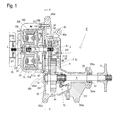
- Fig. 1 is a sectional plan view of an alternative electric transaxle unit C having a casing 300 dividable into left, right and middle casing parts by vertical surfaces.
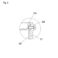
- Fig. 2 is a sectional plan view of a portion of electric transaxle unit C where a motor shaft supporter is engaged with the middle casing part via a dowel pin.
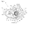
- Fig. 3 is a cross sectional view taken along Y-Y ling of Fig. 1 .
- Fig. 4 is a cross sectional view taken along Z-Z line of Fig. 3 .
- Fig. 5 is a cross sectional view of a mower unit MU
- Electric transaxle unit C includes a casing 300.
- An axle 4 projects laterally outward from casing 300.
- Casing 300 has later-discussed divisional casing parts 310, 311, and 312, and bosses 300a having vertical penetrating bolt holes are formed on casing parts 310, 311, and 312 so as to serve as portions to be attached to a vehicle body frame 10.
- vehicle body frame 10 has tabs 320 to be fitted onto top surfaces of bosses 300a, and tabs 320 are fastened to casing 300 by screwing respective bolts 321 into respective boss holes of bosses 300a, as shown in Fig. 3 .
- casing 300 On the assumption that axle 4 supported by casing 300 is disposed on a horizontal phantom surface, casing 300 is shaped so as to have the horizontal phantom surface equidistant from top and bottom ends of bosses 300a. Therefore, when a pair of electric transaxle units C are arranged so that one corresponds to the other vertically inversed, thereby serving as left and right electric transaxle units C, the top surfaces of bosses 300a of respective left and right electric transaxle units C are disposed at equal heights so as to be convenient to their fitting to tabs 320 of vehicle body frame 10.
- casing 300 can be vertically inversed so as to selectively serve as either casing 300 of left electric transaxle unit C from which axle 4 projects leftwardly outward or casing 300 of right electric transaxle unit C from which axle 4 projects rightwardly outward. Further, an axis of a motor shaft 3 is disposed on the horizontal phantom surface.
- Casing 300 is not dividable into upper and lower divisional parts by a horizontal surface, however, it is dividable into left, middle and right divisional casing parts 310, 311 and 312 by vertical surfaces.
- Axle supporting casing part 312 is joined at a left or right vertical open surface to a vertical open surface of middle casing part 311, and casing parts 311 and 312 are fastened to each other by bolts 341 shown in Fig. 3 , thereby constituting a gear chamber GC therein.
- Motor casing part 310 forming a motor chamber MC therein is joined at a vertical open surface to a right or left vertical surface of middle casing part 311 laterally opposite to axle supporting casing part 312 with respect to middle casing part 311, and is fastened to middle casing part 311 by bolts 340 as shown in Figs. 1 and 3 .
- Electric motor assembly 302 includes motor shaft 3, a drum-shaped rotor 35 fixed on motor shaft 3, and permanent magnets 36 fixed on the inner peripheral surface of the outer peripheral portion of rotor 35.
- Electric motor assembly 302 includes a cup-shaped stator 330 disposed coaxially to motor shaft 3. Armature windings 34 are fixed on an outer peripheral surface of stator 330 so as to face permanent magnets 36 of rotor 35 therearound.
- Stator 330 is fixed to an inside portion of a vertical wall of motor casing part 310 at an axial end thereof opposite to gear chamber GC.
- a central boss 35b of rotor 35 fixed on motor shaft 3 is disposed in cup-shaped stator 330, and a vertical end surface of stator 330, laterally opposite to the projection direction of axle 4 outward from casing 300, is fixed to an inside surface of a vertical wall of motor casing part 310.
- a central hole 330a is provided in the vertical surface of stator 330, and motor shaft 3 projecting outward from central boss 35b of rotor 35 is passed through central hole 330a of stator 330.
- Bearing 43 and a fluid seal 331 are fitted in the vertical wall of motor casing part 310 so as to neighbor central hole 330a of stator 330.
- Motor shaft 3 passed through hole 330a is passed through bearing 43 and fluid seal 331.
- a wire-gathering box 335 is fixed onto an outer surface of the vertical wall of motor casing part 310.
- An outer end portion of motor shaft 3 passed through fluid seal 331 is freely rotatably passed through wire-gathering box 335, and a cooling fan 25 is fixed on an outer end of motor shaft 3.
- a harness 85 which is electrically connected to armature windings 34, is connected to wire-gathering box 332 exposed on motor casing part 310 of casing 300, as shown in Fig. 4 . Therefore, casing 300 does not need to have a hole for passage of harness 85 or a seal to be fitted in the hole.
- electric motor assembly 302 is provided with an annular convex 35c formed on a cup-shaped portion 35a of rotor 35, a detected member 35d provided on the inner peripheral surface of annular convex 35c of rotor 35, and a rotation angle detector 38 for detecting a rotational position of detected member 35d.
- Rotation angle detector 38 is fixed to a motor shaft support frame 337.
- Motor shaft support frame 337 is not fixed to stator 330 similar to motor shaft support frame 37, but it is disposed along middle casing part 311 and is fixedly clamped between casing parts 310 and 311.
- a harness 88 connected to rotation angle detector 38 is passed through motor shaft support frame 337 and middle casing part 311 as discussed later with reference to Fig. 4 .
- Motor shaft support frame 337 has a central boss 337a in which a bearing 42 is fitted.
- Motor shaft support frame 337 with bearing 42 is fitted and retained on middle casing part 311 by a doweling pin or doweling pins 338 as shown in Figs. 2 and 3 , before attachment of installation of motor casing part 310 to middle casing part 311 while motor casing part 310 incorporating electric motor assembly 302 as an assembly of motor shaft 3, stator 330 and rotor 330.
- a ring-shaped net serving as a fluid filter 350 is fitted between an outer peripheral surface of central boss 337a and an inner peripheral surface of a circular hole 311a of middle casing part 311 surrounding central boss 337a.
- Rotation angle detector 38 is fixed on motor shaft support frame 337.
- a pair of upper and lower holes 337b of motor shaft support frame 337 coincide to a pair of upper and lower holes 311b of middle casing part 311, respectively.
- Either the pair of coinciding upper holes 337b and 311b or the pair of coinciding lower holes 337b and 311b are selected (in this embodiment, upper holes 337b and 311b are selected), and electric wires 88a of harness 88 are passed through selected coinciding holes 337b and 311b so as to be connected to rotation angle detector 38.
- a pipe joint 339 is fitted into selected hole 311b (in this embodiment, upper hole 311b) of middle casing part 311, and projects at an outer end thereof outward from middle casing part 311.
- a protection pipe 88b surrounding electric wires 88a of harness 88 is connected at an end thereof to the outer end of pipe joint 339.
- the remaining hole 311b (in this embodiment, lower hole 311b) is closed by a plug 342 screwed therein.
- motor casing part 310 surrounding a vertical opening is fitted onto a vertical surface of middle casing part 311 while an annular step formed on the outer peripheral edge portion of motor casing part 310 is fitted to the outer peripheral edge of motor shaft support frame 337.
- motor shaft 3 is passed through bearing 42 in motor shaft support frame 337, and detected member 35d fixed on rotor 35 is disposed to face rotation angle detector 38 fixed on middle casing part 311.
- motor shaft support frame 337 comes to be clamped between the outer peripheral edge portion of motor casing part 310 and the vertical surface of middle casing part 311, and the outer peripheral portion of motor casing part 310 is fastened to middle casing part 311 by bolts 340 so as to complete attachment of motor casing part 310 incorporating electric motor assembly 302 to middle casing part 311, whereby casing 300 is provided therein with motor chamber MC incorporating electric motor assembly 302.
- axle-supporting casing part 312 is not attached to middle casing part 311, i.e., gear chamber CG is uncompleted, and the vertical side surface of middle casing part 311 laterally opposite to motor casing part 311 has a wide opening.
- the output end portion of motor shaft 3 projects outward from bearing 42 in motor shaft support frame 337 so as to enter the cavity of middle casing part 311.
- a motor output gear 65 and a brake rotor 62 are fitted onto the projecting output end portion of motor shaft 3, and other components of a brake mechanism Br and a deceleration gear train G are installed into the cavity of middle casing part 311.
- middle casing part 311 is formed vertically opposite upper and lower bosses 300b and 300c for supporting vertical brake shaft 61 therein, as shown in Fig. 3 .
- Boss 300b is closed outward so as not to have the end of brake shaft 61 projecting outward therefrom, and boss 300c is vertically penetrated so as to be opened outward.
- Boss 300b is disposed above or below boss 300c depending on whether electric transaxle unit C serves as a left unit or a right unit corresponding to the vertically inversed left unit.
- a cranked brake arm 60 is fixed on the end of vertical brake shaft 61 projecting outward from boss 300c so as to have a connection end 60a, which is constantly disposed at the same height as the axis of axle 4 regardless of whether boss 300c is above or below boss 300b (in this embodiment, boss 300c serves as the lower boss below boss 300b).
- Operable end 60a is connected to a link member, such as a wire or a rod, extended from a braking operation device provided in a vehicle so as to be mechanically connected to the braking operation device, or is connected to an active portion of an electric actuator (not shown) so as to be electrically connected to the braking operation device.
- each of axial opposite ends of a counter shaft 66 is not clamped between divisional casing parts but it is fitted into each of circularly shaped bosses 311c and 312c of respective casing parts 311 and 312.
- gears 67 and 68 are fitted on counter shaft 66.
- a bearing 51 for journaling an end of axle 4 is fitted in a boss 311d formed in middle casing part 311 before attachment of axle-supporting casing part 312 to middle casing part 311.
- axle 4 is supported by axle-supporting casing part 312 via a bearing 52 and a fluid seal 53, and is provided thereon with a final gear 69 and a clutch TC for towing the vehicle, and a discoid magnet 345 for trapping metal powder caused by rubbing of gears is fastened to a wall of axle-supporting casing part 312 by a bolt.
- axle-supporting casing part 312 When axle-supporting casing part 312 is attached to middle casing part 311, the projecting end of counter shaft 66 is fitted into boss 312c, and an end of axle 4 is fitted into bearing 51, and brake pad 64 is disposed between brake rotor 62 and a wall of axle-supporting casing part 312. Finally, axle-supporting casing part 312 is fastened to middle casing part 311 by bolts 341, thereby completing electric transaxle unit C.
- Electric transaxle unit C is adaptable to a riding lawn mower having a mid-mounted mower unit, a riding lawn mower having a front-mounted mower unit, a wheelchair, and various industrial vehicles such as a skid steering loader.
- the lawn mower equipped with right and left electric transaxle units C is further equipped with a mower unit MU.
- mower unit MU including a mower deck 19, blades 20 and motor assemblies 21 with reference to Fig. 5 .
- Mower deck 19 incorporates blades 20, and is vertically movably supported below vehicle body frame 10 via a suspension link 19a such as show in Fig. 5 .
- Each blade 20 has a vertical drive shaft 20a at a center axis thereof, and is provided on drive shaft 20a with a motor assembly 21 serving as an electric motor for controlling driving of corresponding blade 20.
- the lawn mower is equipped with an unshown mower driving on/off setting operation device (such as a switch or a lever) for selecting either driving or non-driving of blades 20.
- motor assembly 21 includes a rotor 212 and a stator 215.
- Rotor 212 is fixed on drive shaft 20a rotatably integrally with drive shaft 20a.
- Stator 215 is fitted on drive shaft 20a via bearings 214 rotatably relative to drive shaft 20a.
- An upwardly opened cup-shaped rotor 212 is fixed onto drive shaft 20a at a center bottom portion thereof, and is extended vertically upward from the center bottom portion thereof so as to have permanent magnets 213 fixed on an inner peripheral surface thereof.
- Armature windings 216 are fixed onto an outer peripheral surface of a vertical core portion thereof fitted around drive shaft 20a via bearings 214 so as to face permanent magnets 213.
- motor assembly 21 is flattened to have a vertical axial length and a horizontal diametric width that is larger than the vertical axial length, and is disposed within mower deck 19, whereby a top portion of mower deck 19 is formed as a horizontal flat plate-shaped portion without an upper portion of motor assembly 21 projecting therefrom. Therefore, the limit position of mower unit MU when raised can be heightened without interfering with the vehicle body of the lawn mower.
- a top portion of stator 215 is expanded in a horizontal discoid shape, and is vibro-isolatedly secured to the horizontal top plate portion of mower deck 19 together with a rotor support frame 219 via vibro-isolating rubbers 217 and bolts-and-nuts 218.
- An opening 19b is opened in the horizontal discoid top portion of mower deck 19 so as to face a top surface of stator 212.
- a wire-collection box 221 is fixed on the top surface of stator 215 and is disposed in opening 19b, and harness 87 is extended upward from wire-collection box 221.
- a bellow 222 is extended upward from the horizontal top plate portion of mower deck 19 so as to cover opening 19b, wire-collection box 221 and harness 87.
- Rotor support frame 219 is extended downward from a top portion thereof fastened to mower deck 19 via vibro-isolated rubbers 217 and bolts-and-nuts 218 so as to journal the bottom portion of rotor 212 via a bearing 220 at a bottom portion thereof.
- An upwardly opened cup-shaped protector 211 is fixed at a center bottom portion thereof onto drive shaft 20a between the center bottom portion of rotor 212 and the center portion of blade 20.
- stator 215 and rotor support frame 219 are secured to mower deck 19, and meanwhile, rotor 212, protector 211, blade 20 and drive shaft 20a are rotatable integrally with one another, and are rotatable relative to stator 215 and rotor support frame.
- Mower deck 19 is formed with vent holes 19c in a vertical plate-shaped portion thereof so as to introduce the outside air thereinto.
- Protector 211 is formed with air suction holes 211a in a peripheral vertical plate-like portion thereof, with fan blades 211b projecting from respective air suction holes 211a, and with air discharge holes 211c in a horizontal bottom plate-like portion thereof. Therefore, protector 211 rotates together with blade 20 so as to introduce air into mower deck 19 via vent holes 19c, and thereinto via air suction holes 211a, to blow the air onto motor assembly 21, and to discharge the air outward therefrom via air discharge holes 211b.
- arrows define this flow of air. In this way, protector 211 protects mower assembly 21 from grass mowed by blade 20 as a main function thereof, and also serves as a cooling fan for motor assembly 21.
- Mower unit MU illustrated in the present application is provided with motor assemblies 21 provided on drive shafts 20a of respective blades 20.
- one of blades 20 may serve as a drive blade 20 provided with motor assembly 21 on drive shaft 20a thereof, and drive shafts 20a of the other blades 20 may be drivingly connected to drive shaft 20a of drive blade 20 via a belt or the like.
Landscapes
- Engineering & Computer Science (AREA)
- Power Engineering (AREA)
- Chemical & Material Sciences (AREA)
- Combustion & Propulsion (AREA)
- Transportation (AREA)
- Mechanical Engineering (AREA)
- Life Sciences & Earth Sciences (AREA)
- Environmental Sciences (AREA)
- Arrangement Or Mounting Of Propulsion Units For Vehicles (AREA)
- Connection Of Motors, Electrical Generators, Mechanical Devices, And The Like (AREA)
- Harvester Elements (AREA)
- Motor Or Generator Frames (AREA)
Applications Claiming Priority (2)
| Application Number | Priority Date | Filing Date | Title |
|---|---|---|---|
| US12/634,098 US8701806B2 (en) | 2009-03-18 | 2009-12-09 | Electric transaxle unit |
| EP10158564A EP2332760B1 (fr) | 2009-12-09 | 2010-03-31 | Unité de boîte-pont électrique |
Related Parent Applications (2)
| Application Number | Title | Priority Date | Filing Date |
|---|---|---|---|
| EP10158564A Division-Into EP2332760B1 (fr) | 2009-12-09 | 2010-03-31 | Unité de boîte-pont électrique |
| EP10158564.4 Division | 2010-03-31 |
Publications (2)
| Publication Number | Publication Date |
|---|---|
| EP2444265A1 true EP2444265A1 (fr) | 2012-04-25 |
| EP2444265B1 EP2444265B1 (fr) | 2013-06-05 |
Family
ID=43067031
Family Applications (2)
| Application Number | Title | Priority Date | Filing Date |
|---|---|---|---|
| EP10158564A Active EP2332760B1 (fr) | 2009-12-09 | 2010-03-31 | Unité de boîte-pont électrique |
| EP11192237.3A Active EP2444265B1 (fr) | 2009-12-09 | 2010-03-31 | Unité de boîte-pont électrique |
Family Applications Before (1)
| Application Number | Title | Priority Date | Filing Date |
|---|---|---|---|
| EP10158564A Active EP2332760B1 (fr) | 2009-12-09 | 2010-03-31 | Unité de boîte-pont électrique |
Country Status (3)
| Country | Link |
|---|---|
| EP (2) | EP2332760B1 (fr) |
| JP (2) | JP5504461B2 (fr) |
| CN (1) | CN102092279B (fr) |
Cited By (19)
| Publication number | Priority date | Publication date | Assignee | Title |
|---|---|---|---|---|
| DE102011080036A1 (de) * | 2011-07-28 | 2013-01-31 | Zf Friedrichshafen Ag | Radnahe Antriebseinheit für ein Kraftfahrzeug |
| CN103879275A (zh) * | 2012-12-21 | 2014-06-25 | 现代摩比斯株式会社 | 轮内马达总成 |
| EP3446908A1 (fr) * | 2017-08-18 | 2019-02-27 | ArvinMeritor Technology, LLC | Ensemble d'essieu ayant un module de moteur électrique |
| US10500941B2 (en) | 2017-08-18 | 2019-12-10 | Arvinmeritor Technology, Llc | Axle assembly having an electric motor module and a shift mechanism |
| US10500940B2 (en) | 2017-08-18 | 2019-12-10 | Arvinmeritor Technology, Llc | Axle assembly having an electric motor module and a gear reduction module |
| US10704597B2 (en) | 2018-11-30 | 2020-07-07 | Arvinmeritor Technology, Llc | Axle assembly having a bearing preload module |
| US10801602B2 (en) | 2018-11-30 | 2020-10-13 | Arvinmeritor Technology, Llc | Axle assembly having counterphase planet gears |
| US10808834B2 (en) | 2018-11-30 | 2020-10-20 | Arvinmeritor Technology, Llc | Axle assembly and method of control |
| US10808830B2 (en) | 2018-11-30 | 2020-10-20 | Arvinmeritor Technology, Llc | Axle assembly with multiple lubricant chambers |
| US10935120B2 (en) | 2018-11-30 | 2021-03-02 | Arvinmeritor Technology, Llc | Axle assembly having a spigot bearing assembly |
| US10985635B2 (en) | 2018-11-30 | 2021-04-20 | Arvinmeritor Technology, Llc | Axle assembly having a resolver and a method of assembly |
| US10989288B1 (en) | 2019-10-07 | 2021-04-27 | Arvinmeritor Technology, Llc | Axle assembly having a multi-speed countershaft transmission |
| US11038396B2 (en) | 2018-11-30 | 2021-06-15 | Arvinmeritor Technology, Llc | Axle assembly having an electric motor module and method of assembly |
| US11209072B2 (en) | 2019-10-07 | 2021-12-28 | Arvinmeritor Technology, Llc | Axle assembly having a multi-speed transmission |
| US11207976B2 (en) | 2019-10-07 | 2021-12-28 | Arvinmeritor Technology, Llc | Axle assembly having a multi-speed countershaft transmission |
| US11371588B1 (en) | 2021-02-22 | 2022-06-28 | Arvinmeritor Technology, Llc | Axle assembly having a barrel cam |
| US11441644B2 (en) | 2019-10-07 | 2022-09-13 | Arvinmeritor Technology, Llc | Axle assembly having a multi-speed transmission and a drop gear set |
| US11608877B2 (en) | 2021-02-22 | 2023-03-21 | Arvinmeritor Technology, Llc | Axle assembly having a sector cam |
| EP4282679A1 (fr) * | 2022-05-23 | 2023-11-29 | ArvinMeritor Technology, LLC | Unité d'entraînement électrique et système d'essieu moteur |
Families Citing this family (66)
| Publication number | Priority date | Publication date | Assignee | Title |
|---|---|---|---|---|
| EP2389797B1 (fr) * | 2010-05-27 | 2014-11-19 | Kanzaki Kokyukoki Mfg. Co., Ltd. | Tondeuse à gazon électrique |
| JP5615730B2 (ja) * | 2011-02-17 | 2014-10-29 | ヤンマー株式会社 | 電動乗用草刈機 |
| JP5731258B2 (ja) * | 2011-03-31 | 2015-06-10 | 本田技研工業株式会社 | 電動三輪車 |
| JP5789141B2 (ja) * | 2011-07-05 | 2015-10-07 | ヤンマー株式会社 | 電動作業車両 |
| JP5722716B2 (ja) * | 2011-07-14 | 2015-05-27 | ヤンマー株式会社 | 電動作業機 |
| JP2013048608A (ja) * | 2011-08-31 | 2013-03-14 | Kokusan Denki Co Ltd | 電動式作業車両 |
| CN103959611B (zh) * | 2011-11-22 | 2015-12-09 | 本田技研工业株式会社 | 电动机的连接机构 |
| DE102012106740A1 (de) | 2012-07-25 | 2014-01-30 | Dr. Ing. H.C. F. Porsche Aktiengesellschaft | Elektromaschine für ein Hybrid- oder Elektrofahrzeug |
| DE102013204784B4 (de) * | 2013-03-19 | 2018-01-11 | Robert Bosch Gmbh | Elektrische Fahrzeugachsenvorrichtung |
| JP6121213B2 (ja) * | 2013-03-28 | 2017-04-26 | 株式会社クボタ | 乗用作業機及びその運転方法 |
| JP6461683B2 (ja) * | 2015-04-02 | 2019-01-30 | 株式会社クボタ | 電動作業車両 |
| JP6436841B2 (ja) * | 2015-04-09 | 2018-12-12 | 株式会社クボタ | 電動作業車両 |
| FR3038794B1 (fr) * | 2015-07-10 | 2018-08-10 | Valeo Equipements Electriques Moteur | Machine electrique tournante munie d'un moyen de reglage de la position angulaire de l'arbre |
| FR3038792B1 (fr) * | 2015-07-10 | 2018-06-29 | Valeo Equipements Electriques Moteur | Machine electrique tournante a roulement modifie |
| FR3038790B1 (fr) * | 2015-07-10 | 2018-08-10 | Valeo Equipements Electriques Moteur | Machine electrique tournante munie de moyens de positionnement a l'interieur d'un element hote |
| GB201516114D0 (en) * | 2015-09-11 | 2015-10-28 | Agco Int Gmbh | Rotatable agricultural tool |
| CN106717467B (zh) * | 2015-11-20 | 2020-03-31 | 苏州宝时得电动工具有限公司 | 割草机 |
| JP2017103988A (ja) * | 2015-12-04 | 2017-06-08 | 株式会社 神崎高級工機製作所 | 車軸駆動装置 |
| JP6956464B2 (ja) * | 2016-03-04 | 2021-11-02 | Ntn株式会社 | インホイールモータ駆動装置 |
| CN105660032A (zh) * | 2016-03-17 | 2016-06-15 | 福建将乐华辰园林景观照明工程有限公司 | 一种割刀不易钝化的割草装置 |
| US10184860B2 (en) * | 2016-04-08 | 2019-01-22 | Infineon Technologies Ag | Control system for power train control |
| FR3053007B1 (fr) * | 2016-06-28 | 2019-08-23 | France Reducteurs | Transmission, notamment pour engin roulant, et engin roulant equipe d'une telle transmission |
| JP2018070028A (ja) * | 2016-11-01 | 2018-05-10 | Ntn株式会社 | 車両用モータ駆動装置 |
| CN106655579B (zh) * | 2016-11-30 | 2023-07-18 | 青岛敏深风电科技有限公司 | 一种混合动力汽车 |
| JP6907521B2 (ja) * | 2016-12-13 | 2021-07-21 | スズキ株式会社 | 電動車椅子の駆動制御装置 |
| CN108263187B (zh) * | 2016-12-30 | 2021-01-01 | 比亚迪股份有限公司 | 动力传动系统及具有其的车辆 |
| DE102017203587A1 (de) * | 2017-03-06 | 2018-09-06 | Audi Ag | Antriebseinrichtung für ein Kraftfahrzeug und Kraftfahrzeug mit mindestens einer Antriebseinrichtung |
| JP6842994B2 (ja) * | 2017-05-24 | 2021-03-17 | 株式会社クボタ | モーアユニット |
| WO2019058439A1 (fr) * | 2017-09-20 | 2019-03-28 | 本田技研工業株式会社 | Unité électrique |
| CN107745633B (zh) * | 2017-10-13 | 2021-03-23 | 吉林大学 | 一种车辆及其后轮双电机系统 |
| JP2019140756A (ja) * | 2018-02-08 | 2019-08-22 | Ntn株式会社 | インホイールモータ駆動装置、回転電動機、およびハウジングの製造方法 |
| JP7079347B2 (ja) * | 2018-12-26 | 2022-06-01 | 本田技研工業株式会社 | 電動駆動ユニット及び電動車両 |
| JP7199960B2 (ja) | 2018-12-26 | 2023-01-06 | 株式会社クボタ | 電動草刈機 |
| DE202019103778U1 (de) * | 2019-07-09 | 2020-10-12 | Hofer Powertrain Innovation Gmbh | Getriebe, insbesondere verblocktes Einzelradgetriebe mit Entlüftung und verringerter Gefahr des Ölaustritts |
| EP3973210A1 (fr) | 2019-07-09 | 2022-03-30 | hofer powertrain innovation GmbH | Engrenage double |
| FR3101817B1 (fr) * | 2019-10-11 | 2022-06-10 | Idee Services | Ensemble de transmission de puissance et véhicule comprenant cet ensemble |
| CN113573573B (zh) | 2019-10-29 | 2023-06-13 | 南京泉峰科技有限公司 | 骑乘式割草机 |
| EP4019311B1 (fr) * | 2019-11-14 | 2024-11-13 | Aisin Corporation | Dispositif d'entraînement de véhicule |
| KR102240252B1 (ko) * | 2019-11-25 | 2021-04-27 | 주식회사 디아이씨 | 파킹브레이크가 구비된 전기자동차의 액슬장치 |
| KR102240863B1 (ko) * | 2019-11-25 | 2021-04-15 | 주식회사 디아이씨 | 전기자동차의 액슬장치 |
| AU2020417332B2 (en) * | 2019-12-31 | 2024-10-03 | Nanjing Chervon Industry Co., Ltd. | Riding lawnmower |
| CN113115624A (zh) * | 2019-12-31 | 2021-07-16 | 南京德朔实业有限公司 | 骑乘式割草机 |
| JP7082997B2 (ja) * | 2020-03-16 | 2022-06-09 | 本田技研工業株式会社 | 鞍乗型電動三輪車 |
| WO2021190612A1 (fr) | 2020-03-26 | 2021-09-30 | 格力博(江苏)股份有限公司 | Véhicule électrique et système de batterie |
| FR3112727B1 (fr) * | 2020-07-21 | 2022-07-22 | France Reducteurs | Dispositif de transmission et engin roulant équipé d’un tel dispositif de transmission |
| CN111674501A (zh) * | 2020-07-24 | 2020-09-18 | 新大洲本田摩托(苏州)有限公司 | 一种动力系统 |
| JP7390998B2 (ja) * | 2020-09-16 | 2023-12-04 | 株式会社クボタ | 草刈装置 |
| US11722038B2 (en) | 2021-01-13 | 2023-08-08 | Dana Belgium N.V. | Systems and methods for cooling electric motor |
| DE102021109736B4 (de) | 2021-04-19 | 2023-02-23 | Schaeffler Technologies AG & Co. KG | Elektrisch betreibbarer Achsantriebsstrang |
| JP2023034634A (ja) * | 2021-08-31 | 2023-03-13 | 株式会社 神崎高級工機製作所 | 作業車両 |
| CN113872372B (zh) * | 2021-10-22 | 2023-03-24 | 珠海格力电器股份有限公司 | 一种保护结构、油封及电机 |
| DE102021128981B4 (de) | 2021-11-08 | 2024-01-11 | Bayerische Motoren Werke Aktiengesellschaft | Entlüfter mit Druckausgleichsfunktion |
| CN114261266B (zh) * | 2021-12-17 | 2023-10-27 | 安徽皖南新维电机有限公司 | 一种适用于滑移式装载机安装的行走电机 |
| JP2023102121A (ja) * | 2022-01-11 | 2023-07-24 | 株式会社デンソー | 電動駆動装置 |
| DE102022101878A1 (de) | 2022-01-27 | 2023-07-27 | Schaeffler Technologies AG & Co. KG | Elektrisch betreibbarer Achsantriebsstrang |
| DE102022104987A1 (de) | 2022-03-03 | 2023-09-07 | Bayerische Motoren Werke Aktiengesellschaft | Zweiteiliges Gehäuse für eine elektrische Antriebseinheit |
| JP2023178908A (ja) * | 2022-06-06 | 2023-12-18 | 株式会社 神崎高級工機製作所 | 電動作業車両 |
| JP7788994B2 (ja) * | 2022-12-27 | 2025-12-19 | 株式会社クボタ | 電動作業車 |
| EP4450314B1 (fr) * | 2023-04-21 | 2025-08-20 | IMS Gear SE & Co. KGaA | Système d'entraînement et véhicule équipé d'un système d'entraînement |
| EP4570548A1 (fr) * | 2023-10-30 | 2025-06-18 | Kubota Corporation | Véhicule de travail électrique |
| US12594828B2 (en) * | 2023-10-30 | 2026-04-07 | Kubota Corporation | Electric work vehicle |
| US12491951B2 (en) * | 2023-10-30 | 2025-12-09 | Kubota Corporation | Electric work vehicle |
| JP2025084693A (ja) * | 2023-10-30 | 2025-06-03 | 株式会社クボタ | 電動作業車両 |
| US12594829B2 (en) * | 2023-10-30 | 2026-04-07 | Kubota Corporation | Electric work vehicle |
| JP2025087590A (ja) * | 2023-10-30 | 2025-06-10 | 株式会社クボタ | 電動作業車両 |
| US12576704B2 (en) * | 2023-10-30 | 2026-03-17 | Kubota Corporation | Electric work vehicle |
Citations (2)
| Publication number | Priority date | Publication date | Assignee | Title |
|---|---|---|---|---|
| US3404747A (en) * | 1965-12-07 | 1968-10-08 | Acec | Electrical steering wheel with independent suspension |
| DE202005020624U1 (de) * | 2005-09-29 | 2006-06-14 | Zf Friedrichshafen Ag | Antriebseinheit mit optimierter Kühlung |
Family Cites Families (25)
| Publication number | Priority date | Publication date | Assignee | Title |
|---|---|---|---|---|
| US1540526A (en) * | 1922-03-16 | 1925-06-02 | Joseph A Anglada | Motor vehicle |
| JPH01174223U (fr) * | 1988-05-31 | 1989-12-11 | ||
| JPH083191Y2 (ja) * | 1989-02-17 | 1996-01-29 | 株式会社安川電機 | キャンドモータ |
| FR2679842A1 (fr) * | 1991-07-29 | 1993-02-05 | Shm Management Services Ag | Module de roulement moteur, notamment pour vehicule automobile. |
| JP2687816B2 (ja) * | 1992-05-21 | 1997-12-08 | 日産自動車株式会社 | 産業用車両の駆動ユニット |
| US5505101A (en) * | 1993-08-10 | 1996-04-09 | Lloyd S. Curtis | Gearbox |
| DE4421425C1 (de) * | 1994-06-18 | 1995-08-10 | Fichtel & Sachs Ag | Elektrisches Antriebsaggregat für ein Fahrzeug |
| FR2726231B1 (fr) * | 1994-10-27 | 1997-01-17 | Peugeot | Essieu moteur pour vehicule electrique ou hybride |
| JP3584106B2 (ja) * | 1996-01-26 | 2004-11-04 | セイコーエプソン株式会社 | 電気自動車の駆動装置及びその制御方法 |
| JP3697796B2 (ja) * | 1996-10-29 | 2005-09-21 | 松下電器産業株式会社 | 電動機 |
| JP2000069735A (ja) * | 1998-08-25 | 2000-03-03 | Fujitsu General Ltd | アウターロータ型ブラシレス電動機 |
| JP2000135254A (ja) * | 1998-11-02 | 2000-05-16 | Aisin Seiki Co Ltd | 電動式車椅子および車輪電動ユニット |
| JP2000217302A (ja) * | 1999-01-19 | 2000-08-04 | Nippon Densan Corp | モ―タ |
| JP4757983B2 (ja) * | 2000-07-07 | 2011-08-24 | 住友重機械工業株式会社 | 分離型歯車箱、及び、半割箱鋳造用鋳型 |
| JP4190741B2 (ja) * | 2001-04-25 | 2008-12-03 | 本田技研工業株式会社 | クローラベルト車両 |
| JP2006096112A (ja) * | 2004-09-29 | 2006-04-13 | Kanzaki Kokyukoki Mfg Co Ltd | 車軸駆動装置 |
| DE102006014514A1 (de) * | 2006-03-24 | 2007-10-11 | Getrag Innovations Gmbh | Antriebsstrang und Herstell- und Einbauverfahren |
| CN200977848Y (zh) * | 2006-06-27 | 2007-11-21 | 杭州三园工具有限公司 | 电动车底盘 |
| JP2008100609A (ja) * | 2006-10-19 | 2008-05-01 | Yamaha Motor Co Ltd | 電動車両 |
| JP2008132941A (ja) * | 2006-11-29 | 2008-06-12 | Mazda Motor Corp | ホイール駆動装置 |
| JP2008183955A (ja) * | 2007-01-29 | 2008-08-14 | Mazda Motor Corp | 車両用駆動装置の配設構造 |
| JP4755617B2 (ja) * | 2007-03-07 | 2011-08-24 | 本田技研工業株式会社 | インホイールモータ |
| SE531175C2 (sv) * | 2007-05-18 | 2009-01-13 | Scania Cv Abp | Anordning vid ett motorfordon samt ett fordon försett med en sådan anordning |
| CN101311578A (zh) * | 2007-05-25 | 2008-11-26 | 台州市黄岩华阳电动车有限公司 | 电动车驱动变速机构 |
| JP5114772B2 (ja) * | 2007-06-06 | 2013-01-09 | 株式会社小松製作所 | 電動車両の駆動装置 |
-
2010
- 2010-03-31 EP EP10158564A patent/EP2332760B1/fr active Active
- 2010-03-31 EP EP11192237.3A patent/EP2444265B1/fr active Active
- 2010-04-02 JP JP2010086597A patent/JP5504461B2/ja active Active
- 2010-05-19 CN CN201010185544.1A patent/CN102092279B/zh active Active
-
2013
- 2013-10-04 JP JP2013209703A patent/JP2014061880A/ja active Pending
Patent Citations (2)
| Publication number | Priority date | Publication date | Assignee | Title |
|---|---|---|---|---|
| US3404747A (en) * | 1965-12-07 | 1968-10-08 | Acec | Electrical steering wheel with independent suspension |
| DE202005020624U1 (de) * | 2005-09-29 | 2006-06-14 | Zf Friedrichshafen Ag | Antriebseinheit mit optimierter Kühlung |
Cited By (23)
| Publication number | Priority date | Publication date | Assignee | Title |
|---|---|---|---|---|
| DE102011080036A1 (de) * | 2011-07-28 | 2013-01-31 | Zf Friedrichshafen Ag | Radnahe Antriebseinheit für ein Kraftfahrzeug |
| CN103879275A (zh) * | 2012-12-21 | 2014-06-25 | 现代摩比斯株式会社 | 轮内马达总成 |
| CN103879275B (zh) * | 2012-12-21 | 2017-06-30 | 现代摩比斯株式会社 | 轮内马达总成 |
| EP3446908A1 (fr) * | 2017-08-18 | 2019-02-27 | ArvinMeritor Technology, LLC | Ensemble d'essieu ayant un module de moteur électrique |
| US10500941B2 (en) | 2017-08-18 | 2019-12-10 | Arvinmeritor Technology, Llc | Axle assembly having an electric motor module and a shift mechanism |
| US10500940B2 (en) | 2017-08-18 | 2019-12-10 | Arvinmeritor Technology, Llc | Axle assembly having an electric motor module and a gear reduction module |
| US11273700B2 (en) | 2017-08-18 | 2022-03-15 | Arvinmeritor Technology, Llc | Axle assembly having an electric motor module |
| US10935120B2 (en) | 2018-11-30 | 2021-03-02 | Arvinmeritor Technology, Llc | Axle assembly having a spigot bearing assembly |
| US10808834B2 (en) | 2018-11-30 | 2020-10-20 | Arvinmeritor Technology, Llc | Axle assembly and method of control |
| US10808830B2 (en) | 2018-11-30 | 2020-10-20 | Arvinmeritor Technology, Llc | Axle assembly with multiple lubricant chambers |
| US10801602B2 (en) | 2018-11-30 | 2020-10-13 | Arvinmeritor Technology, Llc | Axle assembly having counterphase planet gears |
| US10985635B2 (en) | 2018-11-30 | 2021-04-20 | Arvinmeritor Technology, Llc | Axle assembly having a resolver and a method of assembly |
| US10704597B2 (en) | 2018-11-30 | 2020-07-07 | Arvinmeritor Technology, Llc | Axle assembly having a bearing preload module |
| US11038396B2 (en) | 2018-11-30 | 2021-06-15 | Arvinmeritor Technology, Llc | Axle assembly having an electric motor module and method of assembly |
| US11209072B2 (en) | 2019-10-07 | 2021-12-28 | Arvinmeritor Technology, Llc | Axle assembly having a multi-speed transmission |
| US11207976B2 (en) | 2019-10-07 | 2021-12-28 | Arvinmeritor Technology, Llc | Axle assembly having a multi-speed countershaft transmission |
| US10989288B1 (en) | 2019-10-07 | 2021-04-27 | Arvinmeritor Technology, Llc | Axle assembly having a multi-speed countershaft transmission |
| US11441644B2 (en) | 2019-10-07 | 2022-09-13 | Arvinmeritor Technology, Llc | Axle assembly having a multi-speed transmission and a drop gear set |
| US11680626B2 (en) | 2019-10-07 | 2023-06-20 | Arvinmeritor Technology, Llc | Axle assembly having a multi-speed transmission |
| US11859697B2 (en) | 2019-10-07 | 2024-01-02 | Arvinmeritor Technology, Llc | Axle assembly having a multi-speed transmission and a drop gear set |
| US11371588B1 (en) | 2021-02-22 | 2022-06-28 | Arvinmeritor Technology, Llc | Axle assembly having a barrel cam |
| US11608877B2 (en) | 2021-02-22 | 2023-03-21 | Arvinmeritor Technology, Llc | Axle assembly having a sector cam |
| EP4282679A1 (fr) * | 2022-05-23 | 2023-11-29 | ArvinMeritor Technology, LLC | Unité d'entraînement électrique et système d'essieu moteur |
Also Published As
| Publication number | Publication date |
|---|---|
| JP5504461B2 (ja) | 2014-05-28 |
| JP2011121573A (ja) | 2011-06-23 |
| CN102092279A (zh) | 2011-06-15 |
| JP2014061880A (ja) | 2014-04-10 |
| EP2332760A1 (fr) | 2011-06-15 |
| EP2332760B1 (fr) | 2012-09-12 |
| CN102092279B (zh) | 2015-11-25 |
| EP2444265B1 (fr) | 2013-06-05 |
Similar Documents
| Publication | Publication Date | Title |
|---|---|---|
| EP2444265B1 (fr) | Unité de boîte-pont électrique | |
| US8701806B2 (en) | Electric transaxle unit | |
| EP2374346B1 (fr) | Véhicule de travail électrique à rayon de braquage nul | |
| EP2389797B1 (fr) | Tondeuse à gazon électrique | |
| EP0829196B1 (fr) | Tondeuse à gazon électrique | |
| US7533747B2 (en) | Wheel provided with driving means | |
| US8191342B2 (en) | Riding lawnmower vehicle | |
| JP5028560B2 (ja) | 乗用型芝刈り車両 | |
| US20230068720A1 (en) | Work vehicle | |
| US20060219449A1 (en) | Driving unit for driving vehicle by motor | |
| CA2609666A1 (fr) | Moteur comprenant un actionneur de changement de vitesse | |
| CN105993396A (zh) | 割草机 | |
| JP6925237B2 (ja) | 作業機 | |
| JP2011168237A (ja) | トラクタ | |
| JP3915485B2 (ja) | 乗用芝刈装置 | |
| CN208850222U (zh) | 一种高效便携的花生摘取机 | |
| JP7723832B2 (ja) | 作業機 | |
| JP6976226B2 (ja) | 作業車 | |
| CN223843654U (zh) | 带减速齿的割草电机 | |
| EP3473073B1 (fr) | Appareil de tondeuse | |
| JPH0994022A (ja) | モーア | |
| JP3558550B2 (ja) | 乗用型田植機 | |
| JP2024146425A (ja) | 作業車両用電気モータ付き車軸駆動装置 | |
| JPH06327330A (ja) | 草刈機の集草構造 | |
| JPH04166425A (ja) | 乗用型芝刈機 |
Legal Events
| Date | Code | Title | Description |
|---|---|---|---|
| AC | Divisional application: reference to earlier application |
Ref document number: 2332760 Country of ref document: EP Kind code of ref document: P |
|
| AK | Designated contracting states |
Kind code of ref document: A1 Designated state(s): AT BE BG CH CY CZ DE DK EE ES FI FR GB GR HR HU IE IS IT LI LT LU LV MC MK MT NL NO PL PT RO SE SI SK SM TR |
|
| AX | Request for extension of the european patent |
Extension state: AL BA ME RS |
|
| PUAI | Public reference made under article 153(3) epc to a published international application that has entered the european phase |
Free format text: ORIGINAL CODE: 0009012 |
|
| 17P | Request for examination filed |
Effective date: 20121025 |
|
| GRAP | Despatch of communication of intention to grant a patent |
Free format text: ORIGINAL CODE: EPIDOSNIGR1 |
|
| RIN1 | Information on inventor provided before grant (corrected) |
Inventor name: ITOU, MASAYA C/O KANZAKI KOKYUKOKI MFG. CO., LTD. Inventor name: ISHII, NORIHIRO C/O KANZAKI KOKYUKOKI MFG. CO., LT Inventor name: SASAHARA, KENGO C/O KANZAKI KOKYUKOKI MFG. CO., LT Inventor name: EBIHARA, TOMOYUKI C/O KANZAKI KOKYUKOKI MFG. CO., |
|
| GRAS | Grant fee paid |
Free format text: ORIGINAL CODE: EPIDOSNIGR3 |
|
| GRAA | (expected) grant |
Free format text: ORIGINAL CODE: 0009210 |
|
| AC | Divisional application: reference to earlier application |
Ref document number: 2332760 Country of ref document: EP Kind code of ref document: P |
|
| AK | Designated contracting states |
Kind code of ref document: B1 Designated state(s): AT BE BG CH CY CZ DE DK EE ES FI FR GB GR HR HU IE IS IT LI LT LU LV MC MK MT NL NO PL PT RO SE SI SK SM TR |
|
| REG | Reference to a national code |
Ref country code: GB Ref legal event code: FG4D |
|
| REG | Reference to a national code |
Ref country code: CH Ref legal event code: EP |
|
| REG | Reference to a national code |
Ref country code: AT Ref legal event code: REF Ref document number: 615449 Country of ref document: AT Kind code of ref document: T Effective date: 20130615 |
|
| REG | Reference to a national code |
Ref country code: IE Ref legal event code: FG4D |
|
| REG | Reference to a national code |
Ref country code: DE Ref legal event code: R096 Ref document number: 602010007733 Country of ref document: DE Effective date: 20130801 |
|
| REG | Reference to a national code |
Ref country code: AT Ref legal event code: MK05 Ref document number: 615449 Country of ref document: AT Kind code of ref document: T Effective date: 20130605 |
|
| PG25 | Lapsed in a contracting state [announced via postgrant information from national office to epo] |
Ref country code: SI Free format text: LAPSE BECAUSE OF FAILURE TO SUBMIT A TRANSLATION OF THE DESCRIPTION OR TO PAY THE FEE WITHIN THE PRESCRIBED TIME-LIMIT Effective date: 20130605 Ref country code: AT Free format text: LAPSE BECAUSE OF FAILURE TO SUBMIT A TRANSLATION OF THE DESCRIPTION OR TO PAY THE FEE WITHIN THE PRESCRIBED TIME-LIMIT Effective date: 20130605 Ref country code: LT Free format text: LAPSE BECAUSE OF FAILURE TO SUBMIT A TRANSLATION OF THE DESCRIPTION OR TO PAY THE FEE WITHIN THE PRESCRIBED TIME-LIMIT Effective date: 20130605 Ref country code: FI Free format text: LAPSE BECAUSE OF FAILURE TO SUBMIT A TRANSLATION OF THE DESCRIPTION OR TO PAY THE FEE WITHIN THE PRESCRIBED TIME-LIMIT Effective date: 20130605 Ref country code: ES Free format text: LAPSE BECAUSE OF FAILURE TO SUBMIT A TRANSLATION OF THE DESCRIPTION OR TO PAY THE FEE WITHIN THE PRESCRIBED TIME-LIMIT Effective date: 20130916 Ref country code: SE Free format text: LAPSE BECAUSE OF FAILURE TO SUBMIT A TRANSLATION OF THE DESCRIPTION OR TO PAY THE FEE WITHIN THE PRESCRIBED TIME-LIMIT Effective date: 20130605 Ref country code: GR Free format text: LAPSE BECAUSE OF FAILURE TO SUBMIT A TRANSLATION OF THE DESCRIPTION OR TO PAY THE FEE WITHIN THE PRESCRIBED TIME-LIMIT Effective date: 20130906 Ref country code: NO Free format text: LAPSE BECAUSE OF FAILURE TO SUBMIT A TRANSLATION OF THE DESCRIPTION OR TO PAY THE FEE WITHIN THE PRESCRIBED TIME-LIMIT Effective date: 20130905 |
|
| REG | Reference to a national code |
Ref country code: NL Ref legal event code: VDEP Effective date: 20130605 |
|
| REG | Reference to a national code |
Ref country code: LT Ref legal event code: MG4D |
|
| PG25 | Lapsed in a contracting state [announced via postgrant information from national office to epo] |
Ref country code: BG Free format text: LAPSE BECAUSE OF FAILURE TO SUBMIT A TRANSLATION OF THE DESCRIPTION OR TO PAY THE FEE WITHIN THE PRESCRIBED TIME-LIMIT Effective date: 20130905 Ref country code: HR Free format text: LAPSE BECAUSE OF FAILURE TO SUBMIT A TRANSLATION OF THE DESCRIPTION OR TO PAY THE FEE WITHIN THE PRESCRIBED TIME-LIMIT Effective date: 20130605 |
|
| PG25 | Lapsed in a contracting state [announced via postgrant information from national office to epo] |
Ref country code: LV Free format text: LAPSE BECAUSE OF FAILURE TO SUBMIT A TRANSLATION OF THE DESCRIPTION OR TO PAY THE FEE WITHIN THE PRESCRIBED TIME-LIMIT Effective date: 20130605 |
|
| PG25 | Lapsed in a contracting state [announced via postgrant information from national office to epo] |
Ref country code: IS Free format text: LAPSE BECAUSE OF FAILURE TO SUBMIT A TRANSLATION OF THE DESCRIPTION OR TO PAY THE FEE WITHIN THE PRESCRIBED TIME-LIMIT Effective date: 20131005 Ref country code: PT Free format text: LAPSE BECAUSE OF FAILURE TO SUBMIT A TRANSLATION OF THE DESCRIPTION OR TO PAY THE FEE WITHIN THE PRESCRIBED TIME-LIMIT Effective date: 20131007 Ref country code: BE Free format text: LAPSE BECAUSE OF FAILURE TO SUBMIT A TRANSLATION OF THE DESCRIPTION OR TO PAY THE FEE WITHIN THE PRESCRIBED TIME-LIMIT Effective date: 20130605 Ref country code: EE Free format text: LAPSE BECAUSE OF FAILURE TO SUBMIT A TRANSLATION OF THE DESCRIPTION OR TO PAY THE FEE WITHIN THE PRESCRIBED TIME-LIMIT Effective date: 20130605 Ref country code: SK Free format text: LAPSE BECAUSE OF FAILURE TO SUBMIT A TRANSLATION OF THE DESCRIPTION OR TO PAY THE FEE WITHIN THE PRESCRIBED TIME-LIMIT Effective date: 20130605 Ref country code: CZ Free format text: LAPSE BECAUSE OF FAILURE TO SUBMIT A TRANSLATION OF THE DESCRIPTION OR TO PAY THE FEE WITHIN THE PRESCRIBED TIME-LIMIT Effective date: 20130605 |
|
| PG25 | Lapsed in a contracting state [announced via postgrant information from national office to epo] |
Ref country code: RO Free format text: LAPSE BECAUSE OF FAILURE TO SUBMIT A TRANSLATION OF THE DESCRIPTION OR TO PAY THE FEE WITHIN THE PRESCRIBED TIME-LIMIT Effective date: 20130605 Ref country code: PL Free format text: LAPSE BECAUSE OF FAILURE TO SUBMIT A TRANSLATION OF THE DESCRIPTION OR TO PAY THE FEE WITHIN THE PRESCRIBED TIME-LIMIT Effective date: 20130605 Ref country code: NL Free format text: LAPSE BECAUSE OF FAILURE TO SUBMIT A TRANSLATION OF THE DESCRIPTION OR TO PAY THE FEE WITHIN THE PRESCRIBED TIME-LIMIT Effective date: 20130605 |
|
| PLBE | No opposition filed within time limit |
Free format text: ORIGINAL CODE: 0009261 |
|
| STAA | Information on the status of an ep patent application or granted ep patent |
Free format text: STATUS: NO OPPOSITION FILED WITHIN TIME LIMIT |
|
| PG25 | Lapsed in a contracting state [announced via postgrant information from national office to epo] |
Ref country code: DK Free format text: LAPSE BECAUSE OF FAILURE TO SUBMIT A TRANSLATION OF THE DESCRIPTION OR TO PAY THE FEE WITHIN THE PRESCRIBED TIME-LIMIT Effective date: 20130605 |
|
| 26N | No opposition filed |
Effective date: 20140306 |
|
| REG | Reference to a national code |
Ref country code: DE Ref legal event code: R097 Ref document number: 602010007733 Country of ref document: DE Effective date: 20140306 |
|
| PG25 | Lapsed in a contracting state [announced via postgrant information from national office to epo] |
Ref country code: LU Free format text: LAPSE BECAUSE OF FAILURE TO SUBMIT A TRANSLATION OF THE DESCRIPTION OR TO PAY THE FEE WITHIN THE PRESCRIBED TIME-LIMIT Effective date: 20140331 |
|
| REG | Reference to a national code |
Ref country code: CH Ref legal event code: PL |
|
| GBPC | Gb: european patent ceased through non-payment of renewal fee |
Effective date: 20140331 |
|
| REG | Reference to a national code |
Ref country code: FR Ref legal event code: ST Effective date: 20141128 |
|
| REG | Reference to a national code |
Ref country code: IE Ref legal event code: MM4A |
|
| PG25 | Lapsed in a contracting state [announced via postgrant information from national office to epo] |
Ref country code: GB Free format text: LAPSE BECAUSE OF NON-PAYMENT OF DUE FEES Effective date: 20140331 Ref country code: CH Free format text: LAPSE BECAUSE OF NON-PAYMENT OF DUE FEES Effective date: 20140331 Ref country code: IE Free format text: LAPSE BECAUSE OF NON-PAYMENT OF DUE FEES Effective date: 20140331 Ref country code: LI Free format text: LAPSE BECAUSE OF NON-PAYMENT OF DUE FEES Effective date: 20140331 Ref country code: FR Free format text: LAPSE BECAUSE OF NON-PAYMENT OF DUE FEES Effective date: 20140331 |
|
| PG25 | Lapsed in a contracting state [announced via postgrant information from national office to epo] |
Ref country code: IT Free format text: LAPSE BECAUSE OF NON-PAYMENT OF DUE FEES Effective date: 20140331 |
|
| PG25 | Lapsed in a contracting state [announced via postgrant information from national office to epo] |
Ref country code: MT Free format text: LAPSE BECAUSE OF FAILURE TO SUBMIT A TRANSLATION OF THE DESCRIPTION OR TO PAY THE FEE WITHIN THE PRESCRIBED TIME-LIMIT Effective date: 20130605 |
|
| PG25 | Lapsed in a contracting state [announced via postgrant information from national office to epo] |
Ref country code: SM Free format text: LAPSE BECAUSE OF FAILURE TO SUBMIT A TRANSLATION OF THE DESCRIPTION OR TO PAY THE FEE WITHIN THE PRESCRIBED TIME-LIMIT Effective date: 20130605 |
|
| PG25 | Lapsed in a contracting state [announced via postgrant information from national office to epo] |
Ref country code: MC Free format text: LAPSE BECAUSE OF FAILURE TO SUBMIT A TRANSLATION OF THE DESCRIPTION OR TO PAY THE FEE WITHIN THE PRESCRIBED TIME-LIMIT Effective date: 20130605 |
|
| PG25 | Lapsed in a contracting state [announced via postgrant information from national office to epo] |
Ref country code: CY Free format text: LAPSE BECAUSE OF FAILURE TO SUBMIT A TRANSLATION OF THE DESCRIPTION OR TO PAY THE FEE WITHIN THE PRESCRIBED TIME-LIMIT Effective date: 20130605 |
|
| PG25 | Lapsed in a contracting state [announced via postgrant information from national office to epo] |
Ref country code: HU Free format text: LAPSE BECAUSE OF FAILURE TO SUBMIT A TRANSLATION OF THE DESCRIPTION OR TO PAY THE FEE WITHIN THE PRESCRIBED TIME-LIMIT; INVALID AB INITIO Effective date: 20100331 Ref country code: TR Free format text: LAPSE BECAUSE OF FAILURE TO SUBMIT A TRANSLATION OF THE DESCRIPTION OR TO PAY THE FEE WITHIN THE PRESCRIBED TIME-LIMIT Effective date: 20130605 |
|
| PG25 | Lapsed in a contracting state [announced via postgrant information from national office to epo] |
Ref country code: MK Free format text: LAPSE BECAUSE OF FAILURE TO SUBMIT A TRANSLATION OF THE DESCRIPTION OR TO PAY THE FEE WITHIN THE PRESCRIBED TIME-LIMIT Effective date: 20130605 |
|
| PGFP | Annual fee paid to national office [announced via postgrant information from national office to epo] |
Ref country code: DE Payment date: 20250319 Year of fee payment: 16 |