EP2444827A1 - Optischer Kontakt, Mehrfachstecker und Verfahren zur Verbindung zweier optischer Kontakte - Google Patents
Optischer Kontakt, Mehrfachstecker und Verfahren zur Verbindung zweier optischer Kontakte Download PDFInfo
- Publication number
- EP2444827A1 EP2444827A1 EP20110186020 EP11186020A EP2444827A1 EP 2444827 A1 EP2444827 A1 EP 2444827A1 EP 20110186020 EP20110186020 EP 20110186020 EP 11186020 A EP11186020 A EP 11186020A EP 2444827 A1 EP2444827 A1 EP 2444827A1
- Authority
- EP
- European Patent Office
- Prior art keywords
- ferrule
- contact
- optical
- front face
- type
- Prior art date
- Legal status (The legal status is an assumption and is not a legal conclusion. Google has not performed a legal analysis and makes no representation as to the accuracy of the status listed.)
- Granted
Links
Images
Classifications
-
- G—PHYSICS
- G02—OPTICS
- G02B—OPTICAL ELEMENTS, SYSTEMS OR APPARATUS
- G02B6/00—Light guides; Structural details of arrangements comprising light guides and other optical elements, e.g. couplings
- G02B6/24—Coupling light guides
- G02B6/36—Mechanical coupling means
- G02B6/38—Mechanical coupling means having fibre to fibre mating means
- G02B6/3807—Dismountable connectors, i.e. comprising plugs
- G02B6/381—Dismountable connectors, i.e. comprising plugs of the ferrule type, e.g. fibre ends embedded in ferrules, connecting a pair of fibres
- G02B6/3826—Dismountable connectors, i.e. comprising plugs of the ferrule type, e.g. fibre ends embedded in ferrules, connecting a pair of fibres characterised by form or shape
- G02B6/383—Hermaphroditic connectors, i.e. two identical plugs mating with one another, each plug having both male and female diametrically opposed engaging parts
-
- G—PHYSICS
- G02—OPTICS
- G02B—OPTICAL ELEMENTS, SYSTEMS OR APPARATUS
- G02B6/00—Light guides; Structural details of arrangements comprising light guides and other optical elements, e.g. couplings
- G02B6/24—Coupling light guides
- G02B6/36—Mechanical coupling means
- G02B6/38—Mechanical coupling means having fibre to fibre mating means
- G02B6/3807—Dismountable connectors, i.e. comprising plugs
- G02B6/3873—Connectors using guide surfaces for aligning ferrule ends, e.g. tubes, sleeves, V-grooves, rods, pins, balls
- G02B6/3885—Multicore or multichannel optical connectors, i.e. one single ferrule containing more than one fibre, e.g. ribbon type
-
- G—PHYSICS
- G02—OPTICS
- G02B—OPTICAL ELEMENTS, SYSTEMS OR APPARATUS
- G02B6/00—Light guides; Structural details of arrangements comprising light guides and other optical elements, e.g. couplings
- G02B6/24—Coupling light guides
- G02B6/36—Mechanical coupling means
- G02B6/38—Mechanical coupling means having fibre to fibre mating means
- G02B6/3807—Dismountable connectors, i.e. comprising plugs
- G02B6/381—Dismountable connectors, i.e. comprising plugs of the ferrule type, e.g. fibre ends embedded in ferrules, connecting a pair of fibres
- G02B6/3818—Dismountable connectors, i.e. comprising plugs of the ferrule type, e.g. fibre ends embedded in ferrules, connecting a pair of fibres of a low-reflection-loss type
- G02B6/3821—Dismountable connectors, i.e. comprising plugs of the ferrule type, e.g. fibre ends embedded in ferrules, connecting a pair of fibres of a low-reflection-loss type with axial spring biasing or loading means
-
- G—PHYSICS
- G02—OPTICS
- G02B—OPTICAL ELEMENTS, SYSTEMS OR APPARATUS
- G02B6/00—Light guides; Structural details of arrangements comprising light guides and other optical elements, e.g. couplings
- G02B6/24—Coupling light guides
- G02B6/36—Mechanical coupling means
- G02B6/38—Mechanical coupling means having fibre to fibre mating means
- G02B6/3807—Dismountable connectors, i.e. comprising plugs
- G02B6/3833—Details of mounting fibres in ferrules; Assembly methods; Manufacture
- G02B6/3847—Details of mounting fibres in ferrules; Assembly methods; Manufacture with means preventing fibre end damage, e.g. recessed fibre surfaces
-
- G—PHYSICS
- G02—OPTICS
- G02B—OPTICAL ELEMENTS, SYSTEMS OR APPARATUS
- G02B6/00—Light guides; Structural details of arrangements comprising light guides and other optical elements, e.g. couplings
- G02B6/24—Coupling light guides
- G02B6/36—Mechanical coupling means
- G02B6/38—Mechanical coupling means having fibre to fibre mating means
- G02B6/3807—Dismountable connectors, i.e. comprising plugs
- G02B6/3869—Mounting ferrules to connector body, i.e. plugs
- G02B6/387—Connector plugs comprising two complementary members, e.g. shells, caps, covers, locked together
-
- G—PHYSICS
- G02—OPTICS
- G02B—OPTICAL ELEMENTS, SYSTEMS OR APPARATUS
- G02B6/00—Light guides; Structural details of arrangements comprising light guides and other optical elements, e.g. couplings
- G02B6/24—Coupling light guides
- G02B6/36—Mechanical coupling means
- G02B6/38—Mechanical coupling means having fibre to fibre mating means
- G02B6/3807—Dismountable connectors, i.e. comprising plugs
- G02B6/3873—Connectors using guide surfaces for aligning ferrule ends, e.g. tubes, sleeves, V-grooves, rods, pins, balls
- G02B6/3874—Connectors using guide surfaces for aligning ferrule ends, e.g. tubes, sleeves, V-grooves, rods, pins, balls using tubes, sleeves to align ferrules
- G02B6/3875—Floatingly supported sleeves
-
- G—PHYSICS
- G02—OPTICS
- G02B—OPTICAL ELEMENTS, SYSTEMS OR APPARATUS
- G02B6/00—Light guides; Structural details of arrangements comprising light guides and other optical elements, e.g. couplings
- G02B6/24—Coupling light guides
- G02B6/36—Mechanical coupling means
- G02B6/38—Mechanical coupling means having fibre to fibre mating means
- G02B6/3807—Dismountable connectors, i.e. comprising plugs
- G02B6/3873—Connectors using guide surfaces for aligning ferrule ends, e.g. tubes, sleeves, V-grooves, rods, pins, balls
- G02B6/3874—Connectors using guide surfaces for aligning ferrule ends, e.g. tubes, sleeves, V-grooves, rods, pins, balls using tubes, sleeves to align ferrules
- G02B6/3878—Connectors using guide surfaces for aligning ferrule ends, e.g. tubes, sleeves, V-grooves, rods, pins, balls using tubes, sleeves to align ferrules comprising a plurality of ferrules, branching and break-out means
- G02B6/3879—Linking of individual connector plugs to an overconnector, e.g. using clamps, clips, common housings comprising several individual connector plugs
-
- G—PHYSICS
- G02—OPTICS
- G02B—OPTICAL ELEMENTS, SYSTEMS OR APPARATUS
- G02B6/00—Light guides; Structural details of arrangements comprising light guides and other optical elements, e.g. couplings
- G02B6/24—Coupling light guides
- G02B6/36—Mechanical coupling means
- G02B6/38—Mechanical coupling means having fibre to fibre mating means
- G02B6/3807—Dismountable connectors, i.e. comprising plugs
- G02B6/3873—Connectors using guide surfaces for aligning ferrule ends, e.g. tubes, sleeves, V-grooves, rods, pins, balls
- G02B6/3882—Connectors using guide surfaces for aligning ferrule ends, e.g. tubes, sleeves, V-grooves, rods, pins, balls using rods, pins or balls to align a pair of ferrule ends
-
- G—PHYSICS
- G02—OPTICS
- G02B—OPTICAL ELEMENTS, SYSTEMS OR APPARATUS
- G02B6/00—Light guides; Structural details of arrangements comprising light guides and other optical elements, e.g. couplings
- G02B6/24—Coupling light guides
- G02B6/36—Mechanical coupling means
- G02B6/38—Mechanical coupling means having fibre to fibre mating means
- G02B6/3807—Dismountable connectors, i.e. comprising plugs
- G02B6/389—Dismountable connectors, i.e. comprising plugs characterised by the method of fastening connecting plugs and sockets, e.g. screw- or nut-lock, snap-in, bayonet type
- G02B6/3893—Push-pull type, e.g. snap-in, push-on
-
- Y—GENERAL TAGGING OF NEW TECHNOLOGICAL DEVELOPMENTS; GENERAL TAGGING OF CROSS-SECTIONAL TECHNOLOGIES SPANNING OVER SEVERAL SECTIONS OF THE IPC; TECHNICAL SUBJECTS COVERED BY FORMER USPC CROSS-REFERENCE ART COLLECTIONS [XRACs] AND DIGESTS
- Y10—TECHNICAL SUBJECTS COVERED BY FORMER USPC
- Y10T—TECHNICAL SUBJECTS COVERED BY FORMER US CLASSIFICATION
- Y10T29/00—Metal working
- Y10T29/49—Method of mechanical manufacture
- Y10T29/49826—Assembling or joining
- Y10T29/49895—Associating parts by use of aligning means [e.g., use of a drift pin or a "fixture"]
Definitions
- the present invention relates to an optical contact and a multicontact connector comprising at least one such optical contact.
- optical contacts comprising ferrules receiving the end of ribbons carrying optical fibers. This is for example MT ferrules.
- the face through which a ferrule comes into contact with the ferrule of a complementary type contact is not protected against shocks or scratches that may occur when the optical contact is manipulated, especially when its insertion into a multicontact connector.
- MT type male ferrules may include pins for recentering between two complementary type contacts to connect.
- these pins have low chamfers unsuitable to compensate for significant offsets between two contacts to connect together. This is why it is known, for example from the patent US 6,116,788 , to use a repositioning system to arrange, between the two contacts to connect.
- the mounting of a known optical contact is generally done by arranging the different elements of the optical contact one after the other along an axis. If, during assembly of the contact, one of its elements is forgotten, if an element is incorrectly mounted or if a contact element is damaged, for example when inserting the contact in a connector or in a polymerization oven it may be necessary to dismantle the entire optical contact.
- the ferrule is disposed inside the body and the front face of the ferrule is protected when the latter is disposed in the body.
- the ferrule can thus be encapsulated in the body.
- the ferrule may be an optical ferrule MT or any other type of optical ferrule or any active component for generating or receiving optical signals.
- the ferrule may be mounted movably in the body along an axis parallel to its longitudinal axis.
- the contact comprises for example a spring mounted in the body and one end bears, directly or not, that is to say with or without intermediate parts, against the rear face of the ferrule.
- the spring can be encapsulated in the body.
- the body can be configured to receive only one ferrule.
- the ferrule can come directly into contact with the body when it is received in the latter, without intermediate piece.
- the ferrule may have a rectangular cross-section and each of the side edges of the ferrule may have a shoulder engaging a corresponding shoulder of the body to define a stop for forward movement of the ferrule into the body.
- at least a portion of the body extends beyond the front face of the ferrule outwardly thereof when the ferrule is in this position defining a stop to the front.
- the maximum compression of the spring determined by the stiffness of the latter, can define a stop for the rearward movement of the ferrule in the body.
- the contact may be male type and include at least one pin and a housing for receiving said pin, the latter being disposed parallel to the axis of the ferrule when mounted in said housing, the pin extending beyond from the front face of the ferrule outwardly thereof a second distance, said portion of the body extending beyond the front face of the ferrule having at least one arm extending beyond the front face of the ferrule outwardly thereof on a first distance greater than the second distance.
- the body may have a portion projecting beyond the pins of the male type contact.
- This or these arms may allow, when seeking to connect two complementary type of contacts, to perform a first alignment of the ferrule of the female contact type before it comes into contact with the pins of the ferrule of the contact of male type which provide a second alignment of the female-type contact relative to the male-type contact, which facilitates and improves the centering of two complementary type of optical contacts during their connection.
- the portion extending beyond the front face of the ferrule comprises for example two arms and each of these two arms may extend in the extension of a wall of the body in contact with a lateral edge of the ferrule.
- the distance between the two arms corresponds for example to the distance between the two lateral edges of the ferrule.
- the body may be formed by at least two parts, each of said parts comprising means allowing the removable assembly of a part with another, said means being configured so that the assembly and disassembly of said parts are carried out by exerting a force on the pieces perpendicular to the longitudinal axis of the ferrule.
- the portion of the end of the body extending beyond the front face of the ferrule towards the outside thereof may be carried by only one of the body parts and the portion of the same end of the body. body beyond which the front face of the ferrule may be carried by another of said body parts.
- the body is for example formed by two pieces.
- each piece may have a cutout on a side face, so that when the two pieces are assembled, the cuts are facing one another.
- the contact may have a rectangular cross section, extending along a longitudinal axis parallel to that in which the ferrule extends when it is received in the body.
- the invention further relates, in another of these aspects, a multicontact connector, comprising a housing in which is received at least one contact as defined above.
- the housing comprises, for example, several superposed housings, enabling the contacts in the housing to be stacked.
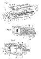
- figure 1 an optical contact designated generally by 1 according to a first example of implementation of the invention.
- This optical contact 1 comprises a body which is formed, in the example in question, by two parts 3 and 4.
- Each of these parts 3 and 4 can define substantially one half of the body, but the invention is not limited to one particular number of parts to form the body 2, nor parts forming only portions of the body of the same dimensions.
- These pieces 2 and 3 form, when assembled together, a parallelepiped-shaped casing along a Y axis, this housing defining a housing 5 in which is received a ferrule, generally denoted by 6, which will be described later.
- each of the parts 3 and 4 comprises means of assembly from one to the other. These means are for example in the form of elastically deformable tabs 10 cooperating with grooves or slots 11 to assemble parts 3 and 4 together.
- the piece 3 may have only lugs 10 and the piece 4 may have only slots or grooves 11 adapted to cooperate with the lugs 10 of the part 3, or vice versa.
- the parts 3 and 4 each comprise tabs 10 and slots or grooves 11.
- These assembly means 10 and 11 are advantageously configured to allow easy assembly and disassembly of the parts 3 and 4 forming the body 2.
- the means 10 and 11 are also configured, in the example described, to allow the assembly to be carried out by exerting on the parts 3 and 4 of the body forces directed perpendicularly to the longitudinal axis Y of the body 2.
- each part 3 and 4 may comprise a cavity 12, the latter being arranged such that when the parts 3 and 4 are assembled to form the body 2, the cavities 12 are superimposed.
- a spring 14 can be disposed inside the body 2, this spring 14 being in particular a compression spring configured to exert a force parallel to the axis Y.
- the body 2 can be made, at least for some of the parts, or for all parts, plastic.
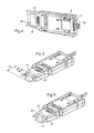
- the ferrule 6 is movably mounted inside the body 2. When the parts 2 and 3 are assembled, at least a portion 36 of the body surrounds the ferrule 6 externally.
- This ferrule 6 is in the example of type MT and rectangular cross-section with respect to a longitudinal axis X of the ferrule.
- the ferrule 6 comprises for example on its lateral edges 15 a shoulder 16 which, by cooperation with a shoulder 17 formed in the internal lateral faces of the body 2, defines a stop for the forward movement of the ferrule 6 inside. of the body 2.
- the spring 14 may comprise an end bearing, directly or not, against the ferrule 6, the compression of the spring defining a stop for the rearward movement of the ferrule 6 in the body 2.
- the longitudinal axis at the ferrule X merges with the longitudinal axis Y of the body 2 when the ferrule 6 is in place in the body 2.
- the rear face 18 of the ferrule 6 comprises a cavity allowing the entry of a bundle of coated optical fibers 20.
- the front face 19 of the ferrule 6 comprises in the example considered a cavity 21, the bundle of optical fibers 20 extending for example between the cavity of the rear face 18 and the cavity 21 inside the ferrule 6.
- the upper face and / or the lower face of the ferrule may have a cutout 23 through which the ribbon 20 is visible when the latter passes through the ferrule 6.
- the front face 19 of the ferrule 6 further comprises in the example described two openings 27 on which open two housings 28 in which pins 29 are arranged when the contact 1 is of the male type, as shown in FIG. figure 5 .
- these elements 30, 31, 32 are carried by only one of the parts forming the body 2, namely the piece 3.
- the other piece 4 forming the body 2 is devoid of such elements 30 to 32.
- L front end along the Y axis of the body 2 of the other piece 4 comprises a portion 35 beyond which the ferrule 6 can extend into positions thereof, particularly in positions close to the position constituting a backstop for its movement in the body 2.
- the elements 30 to 32 extend beyond the front face 19 of the ferrule 6 over a first distance d 1 , this first distance d 1 being greater than the second distance d 2 in which the pins 29 of the ferrule 6 extend beyond said front face 19 when these pins 29 are in place in the housing 28, in particular when the pins 29 extend across the entire ferrule 6.
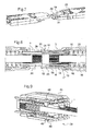
- the contacts When connecting the contact represented to the figure 5 to the contact represented at figure 6 , the contacts are positioned so that the part 2 of each contact comes in front of the piece 3 of the other contact and vice versa. These two contacts are then approached from each other.
- the arms 30 and 32 of the male-type contact shown in FIG. figure 5 guide the front end of the side edges 15 of the ferrule 6 of the female type contact shown in FIG. figure 6 before this ferrule 6 comes into contact with the pins 29 of the ferrule of the male-type contact.
- the introduction into the housing 28 of the ferrule of the female-type contact of the pins of the ferrule 6 of the male-type contact makes it possible to implement a second guiding step between the two. male and female type contacts.
- Male or female contacts 1 as described above can be received within a housing 40 of a multicontact connector 39, for example a multicontact connector.
- This housing 40 is for example configured to receive at least one optical contact, for example between two and ten contacts. These contacts can, as shown in figure 9 , the superposed ones when they are received in the housing 40.
- the contacts and the housing 40 may comprise means allowing the contacts to be removably mounted in the housing.
- This is for example tongues 45 carried by each side face of the body 2, in particular by each side face of each of the parts 3 and 4 forming the body 2, these tongues being pivotable and carrying one or more reliefs 46 that can cooperate with one or more grooves 48 formed in the wall of the housing 40.
Landscapes
- Physics & Mathematics (AREA)
- General Physics & Mathematics (AREA)
- Optics & Photonics (AREA)
- Mechanical Coupling Of Light Guides (AREA)
Applications Claiming Priority (1)
| Application Number | Priority Date | Filing Date | Title |
|---|---|---|---|
| FR1058676A FR2966609B1 (fr) | 2010-10-22 | 2010-10-22 | Contact optique, connecteur multicontact et procede de connexion de deux contacts optiques |
Publications (2)
| Publication Number | Publication Date |
|---|---|
| EP2444827A1 true EP2444827A1 (de) | 2012-04-25 |
| EP2444827B1 EP2444827B1 (de) | 2019-04-03 |
Family
ID=43546222
Family Applications (1)
| Application Number | Title | Priority Date | Filing Date |
|---|---|---|---|
| EP11186020.1A Active EP2444827B1 (de) | 2010-10-22 | 2011-10-20 | Optischer Kontakt, Mehrfachstecker und Verfahren zur Verbindung zweier optischer Kontakte |
Country Status (3)
| Country | Link |
|---|---|
| US (1) | US8961033B2 (de) |
| EP (1) | EP2444827B1 (de) |
| FR (1) | FR2966609B1 (de) |
Cited By (2)
| Publication number | Priority date | Publication date | Assignee | Title |
|---|---|---|---|---|
| EP2947485A1 (de) * | 2014-05-21 | 2015-11-25 | Radiall | Optische verbindungseinheit mit verbesserter führung der optischen kontaktenden, entsprechende kontaktenden mit geringen abmessungen und entsprechendes verbindungsverfahren |
| EP3218968B1 (de) * | 2014-11-11 | 2020-06-10 | Huber+Suhner Ag | Verbinderbaugruppe |
Families Citing this family (3)
| Publication number | Priority date | Publication date | Assignee | Title |
|---|---|---|---|---|
| US9354403B2 (en) * | 2013-09-17 | 2016-05-31 | Avago Technologies General Ip (Singapore) Pte. Ltd. | Optical communications module having a floating ferrule that reduces wiggle loss |
| US9239436B2 (en) * | 2013-11-26 | 2016-01-19 | Corning Cable Systems Llc | Fiber optic plug having an articulated force structure to inhibit angular ferrule biasing during insertion into an optical receptacle, and related assemblies and methods |
| CN112352174A (zh) | 2018-06-29 | 2021-02-09 | 3M创新有限公司 | 带有盒的光学组件 |
Citations (9)
| Publication number | Priority date | Publication date | Assignee | Title |
|---|---|---|---|---|
| EP0505197A2 (de) * | 1991-03-22 | 1992-09-23 | BICC Public Limited Company | Lichtleiterverbindung |
| US6116788A (en) * | 1996-10-11 | 2000-09-12 | Siemens Aktiengesellschaft | Optical plug connector |
| EP1092995A2 (de) * | 1999-10-13 | 2001-04-18 | Tyco Electronics Corporation | Optischer Steckverbinder mit mehreren Modulgehäusen |
| EP1107032A1 (de) * | 1999-12-07 | 2001-06-13 | Molex Incorporated | Faseroptisches Stecker-Modul |
| EP0886798B1 (de) * | 1996-03-12 | 2001-12-12 | Diamond SA | Vorrichtung für die paarweise Verbindung von Lichtwellenleiterkabeln mit einer Vielzahl von parallel angeordneten Lichtwellenleitern |
| US6371659B1 (en) * | 1997-11-28 | 2002-04-16 | Infineon Technologies Ag | Optical connector system |
| US6450698B1 (en) * | 2000-05-09 | 2002-09-17 | Molex Incorporated | Connector assembly floating mount |
| US20060002659A1 (en) * | 2004-07-01 | 2006-01-05 | Teradyne, Inc. | Flexible optical interconnection system |
| WO2006086153A1 (en) * | 2005-02-08 | 2006-08-17 | Molex Incorporated | Hermaphroditic fibre optical connector system |
Family Cites Families (18)
| Publication number | Priority date | Publication date | Assignee | Title |
|---|---|---|---|---|
| US4312564A (en) * | 1977-12-19 | 1982-01-26 | International Business Machines Corp. | Multi-fiber optic connector |
| AU654683B2 (en) * | 1990-11-07 | 1994-11-17 | Bicc Public Limited Company | Optical connection to backplanes |
| US5619604A (en) * | 1996-02-26 | 1997-04-08 | Alcoa Fujikura Limited | Multi-fiber optical connector |
| US5689598A (en) * | 1996-06-11 | 1997-11-18 | Siecor Corporation | Connector block and method for simultaneously mating a plurality of optical fiber connector pairs |
| KR20010030946A (ko) * | 1998-08-07 | 2001-04-16 | 오카야마 노리오 | 광 커넥터용 페룰, 그 성형용 금형, 광 커넥터용 페룰의제조 방법 및, 광 커넥터용 페룰의 검사 방법 |
| DE19905246C1 (de) * | 1999-02-02 | 2000-11-30 | Siemens Ag | Abschlußanordnung für ein Ende eines optischen Kabels |
| US6485192B1 (en) * | 1999-10-15 | 2002-11-26 | Tyco Electronics Corporation | Optical device having an integral array interface |
| US6450697B1 (en) * | 2000-08-24 | 2002-09-17 | Berg Technology, Inc. | Optical connector having a combined guide pin lock and grounding contact |
| TW498980U (en) * | 2001-02-13 | 2002-08-11 | Conn Technology Inc U | Optical fiber connector capable of pre-assembling and polishing |
| US6764225B2 (en) * | 2002-03-01 | 2004-07-20 | Fci Americas Technology, Inc. | Optic fiber connectors |
| US6832858B2 (en) * | 2002-09-13 | 2004-12-21 | Teradyne, Inc. | Techniques for forming fiber optic connections in a modularized manner |
| US6776645B2 (en) * | 2002-12-20 | 2004-08-17 | Teradyne, Inc. | Latch and release system for a connector |
| US7290941B2 (en) * | 2003-12-23 | 2007-11-06 | Amphenol Corporation | Modular fiber optic connector system |
| US7537393B2 (en) * | 2005-06-08 | 2009-05-26 | Commscope, Inc. Of North Carolina | Connectorized fiber optic cabling and methods for forming the same |
| US7572063B2 (en) * | 2005-09-12 | 2009-08-11 | Stratos International, Inc. | Opto-electric connector |
| JP5071045B2 (ja) | 2007-10-26 | 2012-11-14 | 住友電気工業株式会社 | 光コネクタ |
| US8157455B2 (en) * | 2008-02-15 | 2012-04-17 | The Furukawa Electric Co., Ltd. | Optical connector |
| US8672560B2 (en) * | 2010-08-06 | 2014-03-18 | Tyco Electronics Corporation | Hermaphroditic optical fiber ferrule |
-
2010
- 2010-10-22 FR FR1058676A patent/FR2966609B1/fr not_active Expired - Fee Related
-
2011
- 2011-10-12 US US13/271,743 patent/US8961033B2/en active Active
- 2011-10-20 EP EP11186020.1A patent/EP2444827B1/de active Active
Patent Citations (9)
| Publication number | Priority date | Publication date | Assignee | Title |
|---|---|---|---|---|
| EP0505197A2 (de) * | 1991-03-22 | 1992-09-23 | BICC Public Limited Company | Lichtleiterverbindung |
| EP0886798B1 (de) * | 1996-03-12 | 2001-12-12 | Diamond SA | Vorrichtung für die paarweise Verbindung von Lichtwellenleiterkabeln mit einer Vielzahl von parallel angeordneten Lichtwellenleitern |
| US6116788A (en) * | 1996-10-11 | 2000-09-12 | Siemens Aktiengesellschaft | Optical plug connector |
| US6371659B1 (en) * | 1997-11-28 | 2002-04-16 | Infineon Technologies Ag | Optical connector system |
| EP1092995A2 (de) * | 1999-10-13 | 2001-04-18 | Tyco Electronics Corporation | Optischer Steckverbinder mit mehreren Modulgehäusen |
| EP1107032A1 (de) * | 1999-12-07 | 2001-06-13 | Molex Incorporated | Faseroptisches Stecker-Modul |
| US6450698B1 (en) * | 2000-05-09 | 2002-09-17 | Molex Incorporated | Connector assembly floating mount |
| US20060002659A1 (en) * | 2004-07-01 | 2006-01-05 | Teradyne, Inc. | Flexible optical interconnection system |
| WO2006086153A1 (en) * | 2005-02-08 | 2006-08-17 | Molex Incorporated | Hermaphroditic fibre optical connector system |
Cited By (4)
| Publication number | Priority date | Publication date | Assignee | Title |
|---|---|---|---|---|
| EP2947485A1 (de) * | 2014-05-21 | 2015-11-25 | Radiall | Optische verbindungseinheit mit verbesserter führung der optischen kontaktenden, entsprechende kontaktenden mit geringen abmessungen und entsprechendes verbindungsverfahren |
| FR3021415A1 (fr) * | 2014-05-21 | 2015-11-27 | Radiall Sa | Ferule de dimensions reduites pour contact optique, connecteur multi-contacts integrant une pluralite de telles ferules. |
| US9678286B2 (en) | 2014-05-21 | 2017-06-13 | Radiall | Optical connection assembly with improved guiding of the ferrules of optical contacts, ferule with reduced dimensions and connection method associated |
| EP3218968B1 (de) * | 2014-11-11 | 2020-06-10 | Huber+Suhner Ag | Verbinderbaugruppe |
Also Published As
| Publication number | Publication date |
|---|---|
| US8961033B2 (en) | 2015-02-24 |
| EP2444827B1 (de) | 2019-04-03 |
| US20120099819A1 (en) | 2012-04-26 |
| FR2966609A1 (fr) | 2012-04-27 |
| FR2966609B1 (fr) | 2012-12-14 |
Similar Documents
| Publication | Publication Date | Title |
|---|---|---|
| EP0462907B1 (de) | Faseroptischer Stecker mit schneller Verriegelung und Entriegelung | |
| JP5080624B2 (ja) | 光電複合コネクタ及びそのレセプタクル | |
| EP2654137B1 (de) | Sockel eines Multikontaktanschlusses zum Schnellbefestigen auf einer Platte und entsprechendes Montage-/Demontage-Verfahren | |
| EP2947485B1 (de) | Optische verbindungseinheit mit verbesserter führung der optischen kontaktenden, entsprechende stecker und verbindungsverfahren | |
| EP2444827B1 (de) | Optischer Kontakt, Mehrfachstecker und Verfahren zur Verbindung zweier optischer Kontakte | |
| EP2793063B1 (de) | Adapter mit Haltekäfig für einen Multikontakt-Steckverbinder und entsprechender Multikontakt-Steckverbinder | |
| FR2852403A1 (fr) | Connecteur a fibre optique permettant un mouvement important du terminal | |
| EP2821828B1 (de) | Adapter für einen multikontakt-steckverbinder mit gehäuse und entsprechender multikontakt-steckverbinder | |
| FR2475241A1 (fr) | Connecteur pour fibres optiques | |
| EP2445060A1 (de) | Verbindungssystem zwischen elektronischen karten | |
| FR2989846A1 (fr) | Ensemble de connexion a connecteurs multicontacts avec systeme de detrompage par cle | |
| CA2296199C (fr) | Element de connecteur optique a corps monobloc | |
| EP3267232A1 (de) | Verbindungssystem einer vielzahl von steckerstiften an eine monoblockanordnung, bestehend aus einem gehäusepaneel eines elektronischen geräts und einer vielzahl von buchsen | |
| EP3789803A1 (de) | Anordnung zum zusammenbau einer lichtleitfaser mit mindestens zwei mpo-kontaktpaaren | |
| EP2895902B1 (de) | Einteiliger ausrichtungsfassungshalter mit verriegelungsvorrichtung | |
| EP2416193B1 (de) | Optisches Unterwasserverbindungsstück | |
| FR2969400A1 (fr) | Connecteur pour carte de circuit imprime | |
| EP0476024B1 (de) | Verbindung für glasfasern | |
| EP1692554A1 (de) | Optisches kabelverbinderelement mit verbesserten mitteln zum blockieren des endteils des zu verbindenden kabels | |
| CA2296201C (fr) | Element de connecteur pour fibre optique | |
| EP3443396B1 (de) | Optischer steckverbinder und kontaktierungselement für den optischen steckverbinder | |
| FR2685097A1 (fr) | Dispositif pour la connexion reversible de fibres optiques et procede pour la mise en óoeuvre de ce dispositif. | |
| EP4350404A1 (de) | Elektrischer und/oder optischer kontakt mit einem körper und einer kabelmuffe zur vermeidung einer fehlentriegelung einer verbindung, verbinder oder adapter zur aufnahme eines solchen kontaktes | |
| FR2774181A1 (fr) | Dispositif de connexion/deconnexion de deux fibres optiques individuelles et epanouisseur-connecteur pour fibres optiques | |
| EP2690720A1 (de) | Schnellanschluss-Kabelverbinder |
Legal Events
| Date | Code | Title | Description |
|---|---|---|---|
| AK | Designated contracting states |
Kind code of ref document: A1 Designated state(s): AL AT BE BG CH CY CZ DE DK EE ES FI FR GB GR HR HU IE IS IT LI LT LU LV MC MK MT NL NO PL PT RO RS SE SI SK SM TR |
|
| AX | Request for extension of the european patent |
Extension state: BA ME |
|
| PUAI | Public reference made under article 153(3) epc to a published international application that has entered the european phase |
Free format text: ORIGINAL CODE: 0009012 |
|
| 17P | Request for examination filed |
Effective date: 20121024 |
|
| 17Q | First examination report despatched |
Effective date: 20140414 |
|
| STAA | Information on the status of an ep patent application or granted ep patent |
Free format text: STATUS: EXAMINATION IS IN PROGRESS |
|
| GRAP | Despatch of communication of intention to grant a patent |
Free format text: ORIGINAL CODE: EPIDOSNIGR1 |
|
| STAA | Information on the status of an ep patent application or granted ep patent |
Free format text: STATUS: GRANT OF PATENT IS INTENDED |
|
| INTG | Intention to grant announced |
Effective date: 20181206 |
|
| GRAS | Grant fee paid |
Free format text: ORIGINAL CODE: EPIDOSNIGR3 |
|
| GRAA | (expected) grant |
Free format text: ORIGINAL CODE: 0009210 |
|
| STAA | Information on the status of an ep patent application or granted ep patent |
Free format text: STATUS: THE PATENT HAS BEEN GRANTED |
|
| AK | Designated contracting states |
Kind code of ref document: B1 Designated state(s): AL AT BE BG CH CY CZ DE DK EE ES FI FR GB GR HR HU IE IS IT LI LT LU LV MC MK MT NL NO PL PT RO RS SE SI SK SM TR |
|
| REG | Reference to a national code |
Ref country code: GB Ref legal event code: FG4D Free format text: NOT ENGLISH |
|
| REG | Reference to a national code |
Ref country code: CH Ref legal event code: EP Ref country code: AT Ref legal event code: REF Ref document number: 1116447 Country of ref document: AT Kind code of ref document: T Effective date: 20190415 |
|
| REG | Reference to a national code |
Ref country code: DE Ref legal event code: R096 Ref document number: 602011057705 Country of ref document: DE |
|
| REG | Reference to a national code |
Ref country code: IE Ref legal event code: FG4D Free format text: LANGUAGE OF EP DOCUMENT: FRENCH |
|
| REG | Reference to a national code |
Ref country code: NL Ref legal event code: MP Effective date: 20190403 |
|
| REG | Reference to a national code |
Ref country code: LT Ref legal event code: MG4D |
|
| REG | Reference to a national code |
Ref country code: AT Ref legal event code: MK05 Ref document number: 1116447 Country of ref document: AT Kind code of ref document: T Effective date: 20190403 |
|
| PG25 | Lapsed in a contracting state [announced via postgrant information from national office to epo] |
Ref country code: NL Free format text: LAPSE BECAUSE OF FAILURE TO SUBMIT A TRANSLATION OF THE DESCRIPTION OR TO PAY THE FEE WITHIN THE PRESCRIBED TIME-LIMIT Effective date: 20190403 |
|
| PG25 | Lapsed in a contracting state [announced via postgrant information from national office to epo] |
Ref country code: ES Free format text: LAPSE BECAUSE OF FAILURE TO SUBMIT A TRANSLATION OF THE DESCRIPTION OR TO PAY THE FEE WITHIN THE PRESCRIBED TIME-LIMIT Effective date: 20190403 Ref country code: PT Free format text: LAPSE BECAUSE OF FAILURE TO SUBMIT A TRANSLATION OF THE DESCRIPTION OR TO PAY THE FEE WITHIN THE PRESCRIBED TIME-LIMIT Effective date: 20190803 Ref country code: SE Free format text: LAPSE BECAUSE OF FAILURE TO SUBMIT A TRANSLATION OF THE DESCRIPTION OR TO PAY THE FEE WITHIN THE PRESCRIBED TIME-LIMIT Effective date: 20190403 Ref country code: AL Free format text: LAPSE BECAUSE OF FAILURE TO SUBMIT A TRANSLATION OF THE DESCRIPTION OR TO PAY THE FEE WITHIN THE PRESCRIBED TIME-LIMIT Effective date: 20190403 Ref country code: NO Free format text: LAPSE BECAUSE OF FAILURE TO SUBMIT A TRANSLATION OF THE DESCRIPTION OR TO PAY THE FEE WITHIN THE PRESCRIBED TIME-LIMIT Effective date: 20190703 Ref country code: CZ Free format text: LAPSE BECAUSE OF FAILURE TO SUBMIT A TRANSLATION OF THE DESCRIPTION OR TO PAY THE FEE WITHIN THE PRESCRIBED TIME-LIMIT Effective date: 20190403 Ref country code: FI Free format text: LAPSE BECAUSE OF FAILURE TO SUBMIT A TRANSLATION OF THE DESCRIPTION OR TO PAY THE FEE WITHIN THE PRESCRIBED TIME-LIMIT Effective date: 20190403 Ref country code: LT Free format text: LAPSE BECAUSE OF FAILURE TO SUBMIT A TRANSLATION OF THE DESCRIPTION OR TO PAY THE FEE WITHIN THE PRESCRIBED TIME-LIMIT Effective date: 20190403 Ref country code: HR Free format text: LAPSE BECAUSE OF FAILURE TO SUBMIT A TRANSLATION OF THE DESCRIPTION OR TO PAY THE FEE WITHIN THE PRESCRIBED TIME-LIMIT Effective date: 20190403 |
|
| PG25 | Lapsed in a contracting state [announced via postgrant information from national office to epo] |
Ref country code: PL Free format text: LAPSE BECAUSE OF FAILURE TO SUBMIT A TRANSLATION OF THE DESCRIPTION OR TO PAY THE FEE WITHIN THE PRESCRIBED TIME-LIMIT Effective date: 20190403 Ref country code: GR Free format text: LAPSE BECAUSE OF FAILURE TO SUBMIT A TRANSLATION OF THE DESCRIPTION OR TO PAY THE FEE WITHIN THE PRESCRIBED TIME-LIMIT Effective date: 20190704 Ref country code: LV Free format text: LAPSE BECAUSE OF FAILURE TO SUBMIT A TRANSLATION OF THE DESCRIPTION OR TO PAY THE FEE WITHIN THE PRESCRIBED TIME-LIMIT Effective date: 20190403 Ref country code: BG Free format text: LAPSE BECAUSE OF FAILURE TO SUBMIT A TRANSLATION OF THE DESCRIPTION OR TO PAY THE FEE WITHIN THE PRESCRIBED TIME-LIMIT Effective date: 20190703 Ref country code: RS Free format text: LAPSE BECAUSE OF FAILURE TO SUBMIT A TRANSLATION OF THE DESCRIPTION OR TO PAY THE FEE WITHIN THE PRESCRIBED TIME-LIMIT Effective date: 20190403 |
|
| PG25 | Lapsed in a contracting state [announced via postgrant information from national office to epo] |
Ref country code: AT Free format text: LAPSE BECAUSE OF FAILURE TO SUBMIT A TRANSLATION OF THE DESCRIPTION OR TO PAY THE FEE WITHIN THE PRESCRIBED TIME-LIMIT Effective date: 20190403 Ref country code: IS Free format text: LAPSE BECAUSE OF FAILURE TO SUBMIT A TRANSLATION OF THE DESCRIPTION OR TO PAY THE FEE WITHIN THE PRESCRIBED TIME-LIMIT Effective date: 20190803 |
|
| REG | Reference to a national code |
Ref country code: DE Ref legal event code: R097 Ref document number: 602011057705 Country of ref document: DE |
|
| PG25 | Lapsed in a contracting state [announced via postgrant information from national office to epo] |
Ref country code: DK Free format text: LAPSE BECAUSE OF FAILURE TO SUBMIT A TRANSLATION OF THE DESCRIPTION OR TO PAY THE FEE WITHIN THE PRESCRIBED TIME-LIMIT Effective date: 20190403 Ref country code: EE Free format text: LAPSE BECAUSE OF FAILURE TO SUBMIT A TRANSLATION OF THE DESCRIPTION OR TO PAY THE FEE WITHIN THE PRESCRIBED TIME-LIMIT Effective date: 20190403 Ref country code: RO Free format text: LAPSE BECAUSE OF FAILURE TO SUBMIT A TRANSLATION OF THE DESCRIPTION OR TO PAY THE FEE WITHIN THE PRESCRIBED TIME-LIMIT Effective date: 20190403 Ref country code: SK Free format text: LAPSE BECAUSE OF FAILURE TO SUBMIT A TRANSLATION OF THE DESCRIPTION OR TO PAY THE FEE WITHIN THE PRESCRIBED TIME-LIMIT Effective date: 20190403 |
|
| PLBE | No opposition filed within time limit |
Free format text: ORIGINAL CODE: 0009261 |
|
| STAA | Information on the status of an ep patent application or granted ep patent |
Free format text: STATUS: NO OPPOSITION FILED WITHIN TIME LIMIT |
|
| PG25 | Lapsed in a contracting state [announced via postgrant information from national office to epo] |
Ref country code: SM Free format text: LAPSE BECAUSE OF FAILURE TO SUBMIT A TRANSLATION OF THE DESCRIPTION OR TO PAY THE FEE WITHIN THE PRESCRIBED TIME-LIMIT Effective date: 20190403 Ref country code: IT Free format text: LAPSE BECAUSE OF FAILURE TO SUBMIT A TRANSLATION OF THE DESCRIPTION OR TO PAY THE FEE WITHIN THE PRESCRIBED TIME-LIMIT Effective date: 20190403 |
|
| 26N | No opposition filed |
Effective date: 20200106 |
|
| PG25 | Lapsed in a contracting state [announced via postgrant information from national office to epo] |
Ref country code: TR Free format text: LAPSE BECAUSE OF FAILURE TO SUBMIT A TRANSLATION OF THE DESCRIPTION OR TO PAY THE FEE WITHIN THE PRESCRIBED TIME-LIMIT Effective date: 20190403 |
|
| PG25 | Lapsed in a contracting state [announced via postgrant information from national office to epo] |
Ref country code: MC Free format text: LAPSE BECAUSE OF FAILURE TO SUBMIT A TRANSLATION OF THE DESCRIPTION OR TO PAY THE FEE WITHIN THE PRESCRIBED TIME-LIMIT Effective date: 20190403 Ref country code: SI Free format text: LAPSE BECAUSE OF FAILURE TO SUBMIT A TRANSLATION OF THE DESCRIPTION OR TO PAY THE FEE WITHIN THE PRESCRIBED TIME-LIMIT Effective date: 20190403 |
|
| REG | Reference to a national code |
Ref country code: CH Ref legal event code: PL |
|
| PG25 | Lapsed in a contracting state [announced via postgrant information from national office to epo] |
Ref country code: LU Free format text: LAPSE BECAUSE OF NON-PAYMENT OF DUE FEES Effective date: 20191020 Ref country code: LI Free format text: LAPSE BECAUSE OF NON-PAYMENT OF DUE FEES Effective date: 20191031 Ref country code: CH Free format text: LAPSE BECAUSE OF NON-PAYMENT OF DUE FEES Effective date: 20191031 |
|
| REG | Reference to a national code |
Ref country code: BE Ref legal event code: MM Effective date: 20191031 |
|
| PG25 | Lapsed in a contracting state [announced via postgrant information from national office to epo] |
Ref country code: BE Free format text: LAPSE BECAUSE OF NON-PAYMENT OF DUE FEES Effective date: 20191031 |
|
| PG25 | Lapsed in a contracting state [announced via postgrant information from national office to epo] |
Ref country code: IE Free format text: LAPSE BECAUSE OF NON-PAYMENT OF DUE FEES Effective date: 20191020 |
|
| PG25 | Lapsed in a contracting state [announced via postgrant information from national office to epo] |
Ref country code: CY Free format text: LAPSE BECAUSE OF FAILURE TO SUBMIT A TRANSLATION OF THE DESCRIPTION OR TO PAY THE FEE WITHIN THE PRESCRIBED TIME-LIMIT Effective date: 20190403 |
|
| PG25 | Lapsed in a contracting state [announced via postgrant information from national office to epo] |
Ref country code: MT Free format text: LAPSE BECAUSE OF FAILURE TO SUBMIT A TRANSLATION OF THE DESCRIPTION OR TO PAY THE FEE WITHIN THE PRESCRIBED TIME-LIMIT Effective date: 20190403 Ref country code: HU Free format text: LAPSE BECAUSE OF FAILURE TO SUBMIT A TRANSLATION OF THE DESCRIPTION OR TO PAY THE FEE WITHIN THE PRESCRIBED TIME-LIMIT; INVALID AB INITIO Effective date: 20111020 |
|
| PG25 | Lapsed in a contracting state [announced via postgrant information from national office to epo] |
Ref country code: MK Free format text: LAPSE BECAUSE OF FAILURE TO SUBMIT A TRANSLATION OF THE DESCRIPTION OR TO PAY THE FEE WITHIN THE PRESCRIBED TIME-LIMIT Effective date: 20190403 |
|
| P01 | Opt-out of the competence of the unified patent court (upc) registered |
Effective date: 20230921 |
|
| PGFP | Annual fee paid to national office [announced via postgrant information from national office to epo] |
Ref country code: GB Payment date: 20250923 Year of fee payment: 15 |
|
| PGFP | Annual fee paid to national office [announced via postgrant information from national office to epo] |
Ref country code: FR Payment date: 20250925 Year of fee payment: 15 |
|
| PGFP | Annual fee paid to national office [announced via postgrant information from national office to epo] |
Ref country code: DE Payment date: 20250923 Year of fee payment: 15 |