EP2444848B1 - Procédé de fabrication d'un support magnétique et support magnétique obtenu à l'aide de ce procédé - Google Patents
Procédé de fabrication d'un support magnétique et support magnétique obtenu à l'aide de ce procédé Download PDFInfo
- Publication number
- EP2444848B1 EP2444848B1 EP10789197.0A EP10789197A EP2444848B1 EP 2444848 B1 EP2444848 B1 EP 2444848B1 EP 10789197 A EP10789197 A EP 10789197A EP 2444848 B1 EP2444848 B1 EP 2444848B1
- Authority
- EP
- European Patent Office
- Prior art keywords
- magnetic carrier
- particles
- resin composition
- coating
- composition particles
- Prior art date
- Legal status (The legal status is an assumption and is not a legal conclusion. Google has not performed a legal analysis and makes no representation as to the accuracy of the status listed.)
- Not-in-force
Links
- 238000004519 manufacturing process Methods 0.000 title claims description 35
- 239000002245 particle Substances 0.000 claims description 268
- 239000011342 resin composition Substances 0.000 claims description 157
- 238000000576 coating method Methods 0.000 claims description 118
- 238000003756 stirring Methods 0.000 claims description 92
- 239000011248 coating agent Substances 0.000 claims description 91
- 239000007771 core particle Substances 0.000 claims description 53
- 238000000034 method Methods 0.000 claims description 34
- 230000002093 peripheral effect Effects 0.000 claims description 20
- 239000000463 material Substances 0.000 description 55
- 239000000969 carrier Substances 0.000 description 42
- 229920005989 resin Polymers 0.000 description 42
- 239000011347 resin Substances 0.000 description 42
- 238000005259 measurement Methods 0.000 description 27
- 239000011859 microparticle Substances 0.000 description 23
- 229910000859 α-Fe Inorganic materials 0.000 description 21
- 238000011156 evaluation Methods 0.000 description 19
- XLYOFNOQVPJJNP-UHFFFAOYSA-N water Substances O XLYOFNOQVPJJNP-UHFFFAOYSA-N 0.000 description 19
- 230000008569 process Effects 0.000 description 18
- 239000002994 raw material Substances 0.000 description 18
- WYURNTSHIVDZCO-UHFFFAOYSA-N Tetrahydrofuran Chemical compound C1CCOC1 WYURNTSHIVDZCO-UHFFFAOYSA-N 0.000 description 16
- 239000006185 dispersion Substances 0.000 description 13
- IJGRMHOSHXDMSA-UHFFFAOYSA-N Atomic nitrogen Chemical compound N#N IJGRMHOSHXDMSA-UHFFFAOYSA-N 0.000 description 12
- 238000012423 maintenance Methods 0.000 description 12
- 230000000052 comparative effect Effects 0.000 description 11
- 239000000178 monomer Substances 0.000 description 11
- 239000000243 solution Substances 0.000 description 11
- 230000009477 glass transition Effects 0.000 description 10
- 238000012545 processing Methods 0.000 description 10
- SZVJSHCCFOBDDC-UHFFFAOYSA-N iron(II,III) oxide Inorganic materials O=[Fe]O[Fe]O[Fe]=O SZVJSHCCFOBDDC-UHFFFAOYSA-N 0.000 description 9
- 239000000203 mixture Substances 0.000 description 9
- 238000011161 development Methods 0.000 description 8
- 238000002156 mixing Methods 0.000 description 8
- -1 steam Substances 0.000 description 8
- YLQBMQCUIZJEEH-UHFFFAOYSA-N tetrahydrofuran Natural products C=1C=COC=1 YLQBMQCUIZJEEH-UHFFFAOYSA-N 0.000 description 8
- 238000001035 drying Methods 0.000 description 7
- 239000002904 solvent Substances 0.000 description 7
- XEEYBQQBJWHFJM-UHFFFAOYSA-N Iron Chemical compound [Fe] XEEYBQQBJWHFJM-UHFFFAOYSA-N 0.000 description 6
- VYPSYNLAJGMNEJ-UHFFFAOYSA-N Silicium dioxide Chemical compound O=[Si]=O VYPSYNLAJGMNEJ-UHFFFAOYSA-N 0.000 description 6
- 150000001299 aldehydes Chemical class 0.000 description 6
- 238000009826 distribution Methods 0.000 description 6
- 239000000696 magnetic material Substances 0.000 description 6
- 229910052757 nitrogen Inorganic materials 0.000 description 6
- 238000006116 polymerization reaction Methods 0.000 description 6
- 239000007787 solid Substances 0.000 description 6
- 239000004372 Polyvinyl alcohol Substances 0.000 description 5
- 238000004458 analytical method Methods 0.000 description 5
- 238000004581 coalescence Methods 0.000 description 5
- 238000010586 diagram Methods 0.000 description 5
- 230000006872 improvement Effects 0.000 description 5
- 238000002347 injection Methods 0.000 description 5
- 239000007924 injection Substances 0.000 description 5
- 229920000642 polymer Polymers 0.000 description 5
- 229920002451 polyvinyl alcohol Polymers 0.000 description 5
- 238000007639 printing Methods 0.000 description 5
- 239000000523 sample Substances 0.000 description 5
- VVQNEPGJFQJSBK-UHFFFAOYSA-N Methyl methacrylate Chemical group COC(=O)C(C)=C VVQNEPGJFQJSBK-UHFFFAOYSA-N 0.000 description 4
- 229910019089 Mg-Fe Inorganic materials 0.000 description 4
- GWEVSGVZZGPLCZ-UHFFFAOYSA-N Titan oxide Chemical compound O=[Ti]=O GWEVSGVZZGPLCZ-UHFFFAOYSA-N 0.000 description 4
- 239000012736 aqueous medium Substances 0.000 description 4
- 239000011362 coarse particle Substances 0.000 description 4
- 238000001816 cooling Methods 0.000 description 4
- 230000000694 effects Effects 0.000 description 4
- 238000010438 heat treatment Methods 0.000 description 4
- 238000009775 high-speed stirring Methods 0.000 description 4
- 239000004816 latex Substances 0.000 description 4
- 229920000126 latex Polymers 0.000 description 4
- 239000007788 liquid Substances 0.000 description 4
- 229910052751 metal Inorganic materials 0.000 description 4
- 239000002184 metal Substances 0.000 description 4
- 239000005011 phenolic resin Substances 0.000 description 4
- 150000002989 phenols Chemical class 0.000 description 4
- 230000000379 polymerizing effect Effects 0.000 description 4
- 238000010298 pulverizing process Methods 0.000 description 4
- 239000007921 spray Substances 0.000 description 4
- ZWEHNKRNPOVVGH-UHFFFAOYSA-N 2-Butanone Chemical compound CCC(C)=O ZWEHNKRNPOVVGH-UHFFFAOYSA-N 0.000 description 3
- OKKJLVBELUTLKV-UHFFFAOYSA-N Methanol Chemical compound OC OKKJLVBELUTLKV-UHFFFAOYSA-N 0.000 description 3
- 229910052782 aluminium Inorganic materials 0.000 description 3
- 239000011230 binding agent Substances 0.000 description 3
- 238000006243 chemical reaction Methods 0.000 description 3
- 239000002826 coolant Substances 0.000 description 3
- OIWOHHBRDFKZNC-UHFFFAOYSA-N cyclohexyl 2-methylprop-2-enoate Chemical compound CC(=C)C(=O)OC1CCCCC1 OIWOHHBRDFKZNC-UHFFFAOYSA-N 0.000 description 3
- 238000005227 gel permeation chromatography Methods 0.000 description 3
- 239000002609 medium Substances 0.000 description 3
- 229920001225 polyester resin Polymers 0.000 description 3
- 239000004645 polyester resin Substances 0.000 description 3
- 239000003505 polymerization initiator Substances 0.000 description 3
- 229920005990 polystyrene resin Polymers 0.000 description 3
- 239000000047 product Substances 0.000 description 3
- 239000012488 sample solution Substances 0.000 description 3
- 239000000377 silicon dioxide Substances 0.000 description 3
- 238000005406 washing Methods 0.000 description 3
- VZSRBBMJRBPUNF-UHFFFAOYSA-N 2-(2,3-dihydro-1H-inden-2-ylamino)-N-[3-oxo-3-(2,4,6,7-tetrahydrotriazolo[4,5-c]pyridin-5-yl)propyl]pyrimidine-5-carboxamide Chemical compound C1C(CC2=CC=CC=C12)NC1=NC=C(C=N1)C(=O)NCCC(N1CC2=C(CC1)NN=N2)=O VZSRBBMJRBPUNF-UHFFFAOYSA-N 0.000 description 2
- VHUUQVKOLVNVRT-UHFFFAOYSA-N Ammonium hydroxide Chemical compound [NH4+].[OH-] VHUUQVKOLVNVRT-UHFFFAOYSA-N 0.000 description 2
- OYPRJOBELJOOCE-UHFFFAOYSA-N Calcium Chemical compound [Ca] OYPRJOBELJOOCE-UHFFFAOYSA-N 0.000 description 2
- WHXSMMKQMYFTQS-UHFFFAOYSA-N Lithium Chemical compound [Li] WHXSMMKQMYFTQS-UHFFFAOYSA-N 0.000 description 2
- FYYHWMGAXLPEAU-UHFFFAOYSA-N Magnesium Chemical compound [Mg] FYYHWMGAXLPEAU-UHFFFAOYSA-N 0.000 description 2
- 229920000877 Melamine resin Polymers 0.000 description 2
- PXHVJJICTQNCMI-UHFFFAOYSA-N Nickel Chemical compound [Ni] PXHVJJICTQNCMI-UHFFFAOYSA-N 0.000 description 2
- 239000004793 Polystyrene Substances 0.000 description 2
- 239000006087 Silane Coupling Agent Substances 0.000 description 2
- 229910003809 Sr-Fe Inorganic materials 0.000 description 2
- 229920001807 Urea-formaldehyde Polymers 0.000 description 2
- XLOMVQKBTHCTTD-UHFFFAOYSA-N Zinc monoxide Chemical compound [Zn]=O XLOMVQKBTHCTTD-UHFFFAOYSA-N 0.000 description 2
- 230000002776 aggregation Effects 0.000 description 2
- 238000004220 aggregation Methods 0.000 description 2
- XAGFODPZIPBFFR-UHFFFAOYSA-N aluminium Chemical compound [Al] XAGFODPZIPBFFR-UHFFFAOYSA-N 0.000 description 2
- 235000011114 ammonium hydroxide Nutrition 0.000 description 2
- 238000001354 calcination Methods 0.000 description 2
- 229910052791 calcium Inorganic materials 0.000 description 2
- 239000011575 calcium Substances 0.000 description 2
- 239000006229 carbon black Substances 0.000 description 2
- 229920002678 cellulose Polymers 0.000 description 2
- 239000001913 cellulose Substances 0.000 description 2
- 239000000839 emulsion Substances 0.000 description 2
- 238000001914 filtration Methods 0.000 description 2
- 239000012530 fluid Substances 0.000 description 2
- 238000010528 free radical solution polymerization reaction Methods 0.000 description 2
- 229920003063 hydroxymethyl cellulose Polymers 0.000 description 2
- 229940031574 hydroxymethyl cellulose Drugs 0.000 description 2
- 229910052738 indium Inorganic materials 0.000 description 2
- APFVFJFRJDLVQX-UHFFFAOYSA-N indium atom Chemical compound [In] APFVFJFRJDLVQX-UHFFFAOYSA-N 0.000 description 2
- 150000002500 ions Chemical group 0.000 description 2
- 229910052742 iron Inorganic materials 0.000 description 2
- 229910052744 lithium Inorganic materials 0.000 description 2
- 239000011777 magnesium Substances 0.000 description 2
- 229910052749 magnesium Inorganic materials 0.000 description 2
- WPBNNNQJVZRUHP-UHFFFAOYSA-L manganese(2+);methyl n-[[2-(methoxycarbonylcarbamothioylamino)phenyl]carbamothioyl]carbamate;n-[2-(sulfidocarbothioylamino)ethyl]carbamodithioate Chemical compound [Mn+2].[S-]C(=S)NCCNC([S-])=S.COC(=O)NC(=S)NC1=CC=CC=C1NC(=S)NC(=O)OC WPBNNNQJVZRUHP-UHFFFAOYSA-L 0.000 description 2
- 238000000691 measurement method Methods 0.000 description 2
- 238000002844 melting Methods 0.000 description 2
- 230000008018 melting Effects 0.000 description 2
- 239000012299 nitrogen atmosphere Substances 0.000 description 2
- 229920003229 poly(methyl methacrylate) Polymers 0.000 description 2
- 239000004926 polymethyl methacrylate Substances 0.000 description 2
- 229920002223 polystyrene Polymers 0.000 description 2
- USHAGKDGDHPEEY-UHFFFAOYSA-L potassium persulfate Chemical compound [K+].[K+].[O-]S(=O)(=O)OOS([O-])(=O)=O USHAGKDGDHPEEY-UHFFFAOYSA-L 0.000 description 2
- 239000000843 powder Substances 0.000 description 2
- 239000002244 precipitate Substances 0.000 description 2
- 238000007789 sealing Methods 0.000 description 2
- 239000002002 slurry Substances 0.000 description 2
- 125000006850 spacer group Chemical group 0.000 description 2
- TXEYQDLBPFQVAA-UHFFFAOYSA-N tetrafluoromethane Chemical compound FC(F)(F)F TXEYQDLBPFQVAA-UHFFFAOYSA-N 0.000 description 2
- 229920005992 thermoplastic resin Polymers 0.000 description 2
- 229920002554 vinyl polymer Polymers 0.000 description 2
- LNAZSHAWQACDHT-XIYTZBAFSA-N (2r,3r,4s,5r,6s)-4,5-dimethoxy-2-(methoxymethyl)-3-[(2s,3r,4s,5r,6r)-3,4,5-trimethoxy-6-(methoxymethyl)oxan-2-yl]oxy-6-[(2r,3r,4s,5r,6r)-4,5,6-trimethoxy-2-(methoxymethyl)oxan-3-yl]oxyoxane Chemical compound CO[C@@H]1[C@@H](OC)[C@H](OC)[C@@H](COC)O[C@H]1O[C@H]1[C@H](OC)[C@@H](OC)[C@H](O[C@H]2[C@@H]([C@@H](OC)[C@H](OC)O[C@@H]2COC)OC)O[C@@H]1COC LNAZSHAWQACDHT-XIYTZBAFSA-N 0.000 description 1
- VZXTWGWHSMCWGA-UHFFFAOYSA-N 1,3,5-triazine-2,4-diamine Chemical compound NC1=NC=NC(N)=N1 VZXTWGWHSMCWGA-UHFFFAOYSA-N 0.000 description 1
- OHVLMTFVQDZYHP-UHFFFAOYSA-N 1-(2,4,6,7-tetrahydrotriazolo[4,5-c]pyridin-5-yl)-2-[4-[2-[[3-(trifluoromethoxy)phenyl]methylamino]pyrimidin-5-yl]piperazin-1-yl]ethanone Chemical compound N1N=NC=2CN(CCC=21)C(CN1CCN(CC1)C=1C=NC(=NC=1)NCC1=CC(=CC=C1)OC(F)(F)F)=O OHVLMTFVQDZYHP-UHFFFAOYSA-N 0.000 description 1
- HMUNWXXNJPVALC-UHFFFAOYSA-N 1-[4-[2-(2,3-dihydro-1H-inden-2-ylamino)pyrimidin-5-yl]piperazin-1-yl]-2-(2,4,6,7-tetrahydrotriazolo[4,5-c]pyridin-5-yl)ethanone Chemical compound C1C(CC2=CC=CC=C12)NC1=NC=C(C=N1)N1CCN(CC1)C(CN1CC2=C(CC1)NN=N2)=O HMUNWXXNJPVALC-UHFFFAOYSA-N 0.000 description 1
- MTLWTRLYHAQCAM-UHFFFAOYSA-N 2-[(1-cyano-2-methylpropyl)diazenyl]-3-methylbutanenitrile Chemical compound CC(C)C(C#N)N=NC(C#N)C(C)C MTLWTRLYHAQCAM-UHFFFAOYSA-N 0.000 description 1
- WYGWHHGCAGTUCH-UHFFFAOYSA-N 2-[(2-cyano-4-methylpentan-2-yl)diazenyl]-2,4-dimethylpentanenitrile Chemical compound CC(C)CC(C)(C#N)N=NC(C)(C#N)CC(C)C WYGWHHGCAGTUCH-UHFFFAOYSA-N 0.000 description 1
- XXZCIYUJYUESMD-UHFFFAOYSA-N 2-[4-[2-(2,3-dihydro-1H-inden-2-ylamino)pyrimidin-5-yl]-3-(morpholin-4-ylmethyl)pyrazol-1-yl]-1-(2,4,6,7-tetrahydrotriazolo[4,5-c]pyridin-5-yl)ethanone Chemical compound C1C(CC2=CC=CC=C12)NC1=NC=C(C=N1)C=1C(=NN(C=1)CC(=O)N1CC2=C(CC1)NN=N2)CN1CCOCC1 XXZCIYUJYUESMD-UHFFFAOYSA-N 0.000 description 1
- WWSJZGAPAVMETJ-UHFFFAOYSA-N 2-[4-[2-(2,3-dihydro-1H-inden-2-ylamino)pyrimidin-5-yl]-3-ethoxypyrazol-1-yl]-1-(2,4,6,7-tetrahydrotriazolo[4,5-c]pyridin-5-yl)ethanone Chemical compound C1C(CC2=CC=CC=C12)NC1=NC=C(C=N1)C=1C(=NN(C=1)CC(=O)N1CC2=C(CC1)NN=N2)OCC WWSJZGAPAVMETJ-UHFFFAOYSA-N 0.000 description 1
- FYELSNVLZVIGTI-UHFFFAOYSA-N 2-[4-[2-(2,3-dihydro-1H-inden-2-ylamino)pyrimidin-5-yl]-5-ethylpyrazol-1-yl]-1-(2,4,6,7-tetrahydrotriazolo[4,5-c]pyridin-5-yl)ethanone Chemical compound C1C(CC2=CC=CC=C12)NC1=NC=C(C=N1)C=1C=NN(C=1CC)CC(=O)N1CC2=C(CC1)NN=N2 FYELSNVLZVIGTI-UHFFFAOYSA-N 0.000 description 1
- ZWQBZEFLFSFEOS-UHFFFAOYSA-N 3,5-ditert-butyl-2-hydroxybenzoic acid Chemical compound CC(C)(C)C1=CC(C(O)=O)=C(O)C(C(C)(C)C)=C1 ZWQBZEFLFSFEOS-UHFFFAOYSA-N 0.000 description 1
- VPWNQTHUCYMVMZ-UHFFFAOYSA-N 4,4'-sulfonyldiphenol Chemical class C1=CC(O)=CC=C1S(=O)(=O)C1=CC=C(O)C=C1 VPWNQTHUCYMVMZ-UHFFFAOYSA-N 0.000 description 1
- DFGKGUXTPFWHIX-UHFFFAOYSA-N 6-[2-[4-[2-(2,3-dihydro-1H-inden-2-ylamino)pyrimidin-5-yl]piperazin-1-yl]acetyl]-3H-1,3-benzoxazol-2-one Chemical compound C1C(CC2=CC=CC=C12)NC1=NC=C(C=N1)N1CCN(CC1)CC(=O)C1=CC2=C(NC(O2)=O)C=C1 DFGKGUXTPFWHIX-UHFFFAOYSA-N 0.000 description 1
- DEXFNLNNUZKHNO-UHFFFAOYSA-N 6-[3-[4-[2-(2,3-dihydro-1H-inden-2-ylamino)pyrimidin-5-yl]piperidin-1-yl]-3-oxopropyl]-3H-1,3-benzoxazol-2-one Chemical compound C1C(CC2=CC=CC=C12)NC1=NC=C(C=N1)C1CCN(CC1)C(CCC1=CC2=C(NC(O2)=O)C=C1)=O DEXFNLNNUZKHNO-UHFFFAOYSA-N 0.000 description 1
- 239000004925 Acrylic resin Substances 0.000 description 1
- 229920000178 Acrylic resin Polymers 0.000 description 1
- 238000012935 Averaging Methods 0.000 description 1
- 229930185605 Bisphenol Natural products 0.000 description 1
- OKTJSMMVPCPJKN-UHFFFAOYSA-N Carbon Chemical compound [C] OKTJSMMVPCPJKN-UHFFFAOYSA-N 0.000 description 1
- VYZAMTAEIAYCRO-UHFFFAOYSA-N Chromium Chemical compound [Cr] VYZAMTAEIAYCRO-UHFFFAOYSA-N 0.000 description 1
- BRLQWZUYTZBJKN-UHFFFAOYSA-N Epichlorohydrin Chemical compound ClCC1CO1 BRLQWZUYTZBJKN-UHFFFAOYSA-N 0.000 description 1
- WSFSSNUMVMOOMR-UHFFFAOYSA-N Formaldehyde Chemical compound O=C WSFSSNUMVMOOMR-UHFFFAOYSA-N 0.000 description 1
- 229920002153 Hydroxypropyl cellulose Polymers 0.000 description 1
- 229910007960 Li-Fe Inorganic materials 0.000 description 1
- 229910006564 Li—Fe Inorganic materials 0.000 description 1
- 239000004640 Melamine resin Substances 0.000 description 1
- CERQOIWHTDAKMF-UHFFFAOYSA-N Methacrylic acid Chemical compound CC(=C)C(O)=O CERQOIWHTDAKMF-UHFFFAOYSA-N 0.000 description 1
- 239000000020 Nitrocellulose Substances 0.000 description 1
- 239000004677 Nylon Substances 0.000 description 1
- 239000002033 PVDF binder Substances 0.000 description 1
- ISWSIDIOOBJBQZ-UHFFFAOYSA-N Phenol Chemical compound OC1=CC=CC=C1 ISWSIDIOOBJBQZ-UHFFFAOYSA-N 0.000 description 1
- 229930182556 Polyacetal Natural products 0.000 description 1
- 239000004695 Polyether sulfone Substances 0.000 description 1
- 239000004698 Polyethylene Substances 0.000 description 1
- 239000004734 Polyphenylene sulfide Substances 0.000 description 1
- RTAQQCXQSZGOHL-UHFFFAOYSA-N Titanium Chemical compound [Ti] RTAQQCXQSZGOHL-UHFFFAOYSA-N 0.000 description 1
- XSQUKJJJFZCRTK-UHFFFAOYSA-N Urea Chemical compound NC(N)=O XSQUKJJJFZCRTK-UHFFFAOYSA-N 0.000 description 1
- HCHKCACWOHOZIP-UHFFFAOYSA-N Zinc Chemical compound [Zn] HCHKCACWOHOZIP-UHFFFAOYSA-N 0.000 description 1
- FJWGYAHXMCUOOM-QHOUIDNNSA-N [(2s,3r,4s,5r,6r)-2-[(2r,3r,4s,5r,6s)-4,5-dinitrooxy-2-(nitrooxymethyl)-6-[(2r,3r,4s,5r,6s)-4,5,6-trinitrooxy-2-(nitrooxymethyl)oxan-3-yl]oxyoxan-3-yl]oxy-3,5-dinitrooxy-6-(nitrooxymethyl)oxan-4-yl] nitrate Chemical compound O([C@@H]1O[C@@H]([C@H]([C@H](O[N+]([O-])=O)[C@H]1O[N+]([O-])=O)O[C@H]1[C@@H]([C@@H](O[N+]([O-])=O)[C@H](O[N+]([O-])=O)[C@@H](CO[N+]([O-])=O)O1)O[N+]([O-])=O)CO[N+](=O)[O-])[C@@H]1[C@@H](CO[N+]([O-])=O)O[C@@H](O[N+]([O-])=O)[C@H](O[N+]([O-])=O)[C@H]1O[N+]([O-])=O FJWGYAHXMCUOOM-QHOUIDNNSA-N 0.000 description 1
- 230000001133 acceleration Effects 0.000 description 1
- DHKHKXVYLBGOIT-UHFFFAOYSA-N acetaldehyde Diethyl Acetal Natural products CCOC(C)OCC DHKHKXVYLBGOIT-UHFFFAOYSA-N 0.000 description 1
- 150000001241 acetals Chemical class 0.000 description 1
- 150000004996 alkyl benzenes Chemical class 0.000 description 1
- 125000000217 alkyl group Chemical group 0.000 description 1
- PNEYBMLMFCGWSK-UHFFFAOYSA-N aluminium oxide Inorganic materials [O-2].[O-2].[O-2].[Al+3].[Al+3] PNEYBMLMFCGWSK-UHFFFAOYSA-N 0.000 description 1
- 239000007864 aqueous solution Substances 0.000 description 1
- QVGXLLKOCUKJST-UHFFFAOYSA-N atomic oxygen Chemical compound [O] QVGXLLKOCUKJST-UHFFFAOYSA-N 0.000 description 1
- 230000008901 benefit Effects 0.000 description 1
- 229940077388 benzenesulfonate Drugs 0.000 description 1
- 229910052790 beryllium Inorganic materials 0.000 description 1
- ATBAMAFKBVZNFJ-UHFFFAOYSA-N beryllium atom Chemical compound [Be] ATBAMAFKBVZNFJ-UHFFFAOYSA-N 0.000 description 1
- 238000011088 calibration curve Methods 0.000 description 1
- 239000003990 capacitor Substances 0.000 description 1
- 239000004202 carbamide Substances 0.000 description 1
- 150000004649 carbonic acid derivatives Chemical class 0.000 description 1
- 239000003054 catalyst Substances 0.000 description 1
- 229920002301 cellulose acetate Polymers 0.000 description 1
- 239000007795 chemical reaction product Substances 0.000 description 1
- 229910052804 chromium Inorganic materials 0.000 description 1
- 239000011651 chromium Substances 0.000 description 1
- 229910017052 cobalt Inorganic materials 0.000 description 1
- 239000010941 cobalt Substances 0.000 description 1
- GUTLYIVDDKVIGB-UHFFFAOYSA-N cobalt atom Chemical compound [Co] GUTLYIVDDKVIGB-UHFFFAOYSA-N 0.000 description 1
- 239000002131 composite material Substances 0.000 description 1
- 238000010924 continuous production Methods 0.000 description 1
- 229920001577 copolymer Polymers 0.000 description 1
- XCJYREBRNVKWGJ-UHFFFAOYSA-N copper(II) phthalocyanine Chemical compound [Cu+2].C12=CC=CC=C2C(N=C2[N-]C(C3=CC=CC=C32)=N2)=NC1=NC([C]1C=CC=CC1=1)=NC=1N=C1[C]3C=CC=CC3=C2[N-]1 XCJYREBRNVKWGJ-UHFFFAOYSA-N 0.000 description 1
- 230000001955 cumulated effect Effects 0.000 description 1
- 230000003247 decreasing effect Effects 0.000 description 1
- 230000007547 defect Effects 0.000 description 1
- 230000002542 deteriorative effect Effects 0.000 description 1
- 239000002270 dispersing agent Substances 0.000 description 1
- 238000004090 dissolution Methods 0.000 description 1
- 239000000428 dust Substances 0.000 description 1
- 239000003480 eluent Substances 0.000 description 1
- 238000007720 emulsion polymerization reaction Methods 0.000 description 1
- 239000003822 epoxy resin Substances 0.000 description 1
- 239000005038 ethylene vinyl acetate Substances 0.000 description 1
- 238000007667 floating Methods 0.000 description 1
- NBVXSUQYWXRMNV-UHFFFAOYSA-N fluoromethane Chemical compound FC NBVXSUQYWXRMNV-UHFFFAOYSA-N 0.000 description 1
- 239000008098 formaldehyde solution Substances 0.000 description 1
- 238000009472 formulation Methods 0.000 description 1
- 230000004927 fusion Effects 0.000 description 1
- 239000008187 granular material Substances 0.000 description 1
- 238000005469 granulation Methods 0.000 description 1
- 230000003179 granulation Effects 0.000 description 1
- 229910002804 graphite Inorganic materials 0.000 description 1
- 239000010439 graphite Substances 0.000 description 1
- LNEPOXFFQSENCJ-UHFFFAOYSA-N haloperidol Chemical compound C1CC(O)(C=2C=CC(Cl)=CC=2)CCN1CCCC(=O)C1=CC=C(F)C=C1 LNEPOXFFQSENCJ-UHFFFAOYSA-N 0.000 description 1
- 229910052595 hematite Inorganic materials 0.000 description 1
- 239000011019 hematite Substances 0.000 description 1
- FFUAGWLWBBFQJT-UHFFFAOYSA-N hexamethyldisilazane Chemical compound C[Si](C)(C)N[Si](C)(C)C FFUAGWLWBBFQJT-UHFFFAOYSA-N 0.000 description 1
- 239000001863 hydroxypropyl cellulose Substances 0.000 description 1
- 235000010977 hydroxypropyl cellulose Nutrition 0.000 description 1
- 229940071676 hydroxypropylcellulose Drugs 0.000 description 1
- 229910010272 inorganic material Inorganic materials 0.000 description 1
- 239000011147 inorganic material Substances 0.000 description 1
- LIKBJVNGSGBSGK-UHFFFAOYSA-N iron(3+);oxygen(2-) Chemical compound [O-2].[O-2].[O-2].[Fe+3].[Fe+3] LIKBJVNGSGBSGK-UHFFFAOYSA-N 0.000 description 1
- JEIPFZHSYJVQDO-UHFFFAOYSA-N iron(III) oxide Inorganic materials O=[Fe]O[Fe]=O JEIPFZHSYJVQDO-UHFFFAOYSA-N 0.000 description 1
- 230000001788 irregular Effects 0.000 description 1
- 238000004898 kneading Methods 0.000 description 1
- UEGPKNKPLBYCNK-UHFFFAOYSA-L magnesium acetate Chemical compound [Mg+2].CC([O-])=O.CC([O-])=O UEGPKNKPLBYCNK-UHFFFAOYSA-L 0.000 description 1
- 239000011654 magnesium acetate Substances 0.000 description 1
- 229940069446 magnesium acetate Drugs 0.000 description 1
- 235000011285 magnesium acetate Nutrition 0.000 description 1
- VTHJTEIRLNZDEV-UHFFFAOYSA-L magnesium dihydroxide Chemical compound [OH-].[OH-].[Mg+2] VTHJTEIRLNZDEV-UHFFFAOYSA-L 0.000 description 1
- 239000000347 magnesium hydroxide Substances 0.000 description 1
- 229910001862 magnesium hydroxide Inorganic materials 0.000 description 1
- 239000011656 manganese carbonate Substances 0.000 description 1
- 229910000016 manganese(II) carbonate Inorganic materials 0.000 description 1
- JDSHMPZPIAZGSV-UHFFFAOYSA-N melamine Chemical compound NC1=NC(N)=NC(N)=N1 JDSHMPZPIAZGSV-UHFFFAOYSA-N 0.000 description 1
- 239000012528 membrane Substances 0.000 description 1
- 150000002739 metals Chemical class 0.000 description 1
- 229920000609 methyl cellulose Polymers 0.000 description 1
- 239000001923 methylcellulose Substances 0.000 description 1
- 235000010981 methylcellulose Nutrition 0.000 description 1
- 229960002900 methylcellulose Drugs 0.000 description 1
- 238000012986 modification Methods 0.000 description 1
- 230000004048 modification Effects 0.000 description 1
- 229910052759 nickel Inorganic materials 0.000 description 1
- 150000002823 nitrates Chemical class 0.000 description 1
- 229920001220 nitrocellulos Polymers 0.000 description 1
- 229920003986 novolac Polymers 0.000 description 1
- 229920001778 nylon Polymers 0.000 description 1
- 239000011368 organic material Substances 0.000 description 1
- 230000010355 oscillation Effects 0.000 description 1
- 239000001301 oxygen Substances 0.000 description 1
- 229910052760 oxygen Inorganic materials 0.000 description 1
- 239000012188 paraffin wax Substances 0.000 description 1
- 230000037361 pathway Effects 0.000 description 1
- 239000003208 petroleum Substances 0.000 description 1
- 230000000704 physical effect Effects 0.000 description 1
- 229920001643 poly(ether ketone) Polymers 0.000 description 1
- 229920001200 poly(ethylene-vinyl acetate) Polymers 0.000 description 1
- 229920002492 poly(sulfone) Polymers 0.000 description 1
- 229920006122 polyamide resin Polymers 0.000 description 1
- 229920001707 polybutylene terephthalate Polymers 0.000 description 1
- 229920005668 polycarbonate resin Polymers 0.000 description 1
- 239000004431 polycarbonate resin Substances 0.000 description 1
- 229920000647 polyepoxide Polymers 0.000 description 1
- 229920006393 polyether sulfone Polymers 0.000 description 1
- 229920000573 polyethylene Polymers 0.000 description 1
- 229920000139 polyethylene terephthalate Polymers 0.000 description 1
- 239000005020 polyethylene terephthalate Substances 0.000 description 1
- 229920006324 polyoxymethylene Polymers 0.000 description 1
- 229920000069 polyphenylene sulfide Polymers 0.000 description 1
- 229920001451 polypropylene glycol Polymers 0.000 description 1
- 239000011118 polyvinyl acetate Substances 0.000 description 1
- 229920002689 polyvinyl acetate Polymers 0.000 description 1
- 239000004800 polyvinyl chloride Substances 0.000 description 1
- 229920000915 polyvinyl chloride Polymers 0.000 description 1
- 229920002981 polyvinylidene fluoride Polymers 0.000 description 1
- 229920000036 polyvinylpyrrolidone Polymers 0.000 description 1
- 239000001267 polyvinylpyrrolidone Substances 0.000 description 1
- 235000013855 polyvinylpyrrolidone Nutrition 0.000 description 1
- 239000011148 porous material Substances 0.000 description 1
- 238000010992 reflux Methods 0.000 description 1
- 230000000717 retained effect Effects 0.000 description 1
- 229910052701 rubidium Inorganic materials 0.000 description 1
- IGLNJRXAVVLDKE-UHFFFAOYSA-N rubidium atom Chemical compound [Rb] IGLNJRXAVVLDKE-UHFFFAOYSA-N 0.000 description 1
- 238000013341 scale-up Methods 0.000 description 1
- 239000011163 secondary particle Substances 0.000 description 1
- 238000007873 sieving Methods 0.000 description 1
- 229920002545 silicone oil Polymers 0.000 description 1
- AKHNMLFCWUSKQB-UHFFFAOYSA-L sodium thiosulfate Chemical compound [Na+].[Na+].[O-]S([O-])(=O)=S AKHNMLFCWUSKQB-UHFFFAOYSA-L 0.000 description 1
- 235000019345 sodium thiosulphate Nutrition 0.000 description 1
- 238000003980 solgel method Methods 0.000 description 1
- 238000001694 spray drying Methods 0.000 description 1
- 229910052712 strontium Inorganic materials 0.000 description 1
- CIOAGBVUUVVLOB-UHFFFAOYSA-N strontium atom Chemical compound [Sr] CIOAGBVUUVVLOB-UHFFFAOYSA-N 0.000 description 1
- LEDMRZGFZIAGGB-UHFFFAOYSA-L strontium carbonate Chemical compound [Sr+2].[O-]C([O-])=O LEDMRZGFZIAGGB-UHFFFAOYSA-L 0.000 description 1
- 229910000018 strontium carbonate Inorganic materials 0.000 description 1
- 229920003048 styrene butadiene rubber Polymers 0.000 description 1
- 239000006228 supernatant Substances 0.000 description 1
- 230000001629 suppression Effects 0.000 description 1
- 239000004094 surface-active agent Substances 0.000 description 1
- 239000000725 suspension Substances 0.000 description 1
- 238000010557 suspension polymerization reaction Methods 0.000 description 1
- 238000012360 testing method Methods 0.000 description 1
- XOLBLPGZBRYERU-UHFFFAOYSA-N tin dioxide Chemical compound O=[Sn]=O XOLBLPGZBRYERU-UHFFFAOYSA-N 0.000 description 1
- 229910001887 tin oxide Inorganic materials 0.000 description 1
- 229910052719 titanium Inorganic materials 0.000 description 1
- 239000010936 titanium Substances 0.000 description 1
- OGIDPMRJRNCKJF-UHFFFAOYSA-N titanium oxide Inorganic materials [Ti]=O OGIDPMRJRNCKJF-UHFFFAOYSA-N 0.000 description 1
- 238000012546 transfer Methods 0.000 description 1
- XYJRNCYWTVGEEG-UHFFFAOYSA-N trimethoxy(2-methylpropyl)silane Chemical compound CO[Si](OC)(OC)CC(C)C XYJRNCYWTVGEEG-UHFFFAOYSA-N 0.000 description 1
- PZJJKWKADRNWSW-UHFFFAOYSA-N trimethoxysilicon Chemical compound CO[Si](OC)OC PZJJKWKADRNWSW-UHFFFAOYSA-N 0.000 description 1
- 238000011144 upstream manufacturing Methods 0.000 description 1
- 125000000391 vinyl group Chemical group [H]C([*])=C([H])[H] 0.000 description 1
- 239000011800 void material Substances 0.000 description 1
- 229910052725 zinc Inorganic materials 0.000 description 1
- 239000011701 zinc Substances 0.000 description 1
- 239000011787 zinc oxide Substances 0.000 description 1
Images


Classifications
-
- G—PHYSICS
- G03—PHOTOGRAPHY; CINEMATOGRAPHY; ANALOGOUS TECHNIQUES USING WAVES OTHER THAN OPTICAL WAVES; ELECTROGRAPHY; HOLOGRAPHY
- G03G—ELECTROGRAPHY; ELECTROPHOTOGRAPHY; MAGNETOGRAPHY
- G03G9/00—Developers
- G03G9/08—Developers with toner particles
- G03G9/10—Developers with toner particles characterised by carrier particles
- G03G9/107—Developers with toner particles characterised by carrier particles having magnetic components
- G03G9/1075—Structural characteristics of the carrier particles, e.g. shape or crystallographic structure
-
- G—PHYSICS
- G03—PHOTOGRAPHY; CINEMATOGRAPHY; ANALOGOUS TECHNIQUES USING WAVES OTHER THAN OPTICAL WAVES; ELECTROGRAPHY; HOLOGRAPHY
- G03G—ELECTROGRAPHY; ELECTROPHOTOGRAPHY; MAGNETOGRAPHY
- G03G9/00—Developers
- G03G9/08—Developers with toner particles
- G03G9/10—Developers with toner particles characterised by carrier particles
- G03G9/113—Developers with toner particles characterised by carrier particles having coatings applied thereto
- G03G9/1131—Coating methods; Structure of coatings
-
- G—PHYSICS
- G03—PHOTOGRAPHY; CINEMATOGRAPHY; ANALOGOUS TECHNIQUES USING WAVES OTHER THAN OPTICAL WAVES; ELECTROGRAPHY; HOLOGRAPHY
- G03G—ELECTROGRAPHY; ELECTROPHOTOGRAPHY; MAGNETOGRAPHY
- G03G9/00—Developers
- G03G9/08—Developers with toner particles
- G03G9/10—Developers with toner particles characterised by carrier particles
- G03G9/107—Developers with toner particles characterised by carrier particles having magnetic components
- G03G9/108—Ferrite carrier, e.g. magnetite
-
- G—PHYSICS
- G03—PHOTOGRAPHY; CINEMATOGRAPHY; ANALOGOUS TECHNIQUES USING WAVES OTHER THAN OPTICAL WAVES; ELECTROGRAPHY; HOLOGRAPHY
- G03G—ELECTROGRAPHY; ELECTROPHOTOGRAPHY; MAGNETOGRAPHY
- G03G9/00—Developers
- G03G9/08—Developers with toner particles
- G03G9/10—Developers with toner particles characterised by carrier particles
- G03G9/107—Developers with toner particles characterised by carrier particles having magnetic components
- G03G9/108—Ferrite carrier, e.g. magnetite
- G03G9/1085—Ferrite carrier, e.g. magnetite with non-ferrous metal oxide, e.g. MgO-Fe2O3
-
- G—PHYSICS
- G03—PHOTOGRAPHY; CINEMATOGRAPHY; ANALOGOUS TECHNIQUES USING WAVES OTHER THAN OPTICAL WAVES; ELECTROGRAPHY; HOLOGRAPHY
- G03G—ELECTROGRAPHY; ELECTROPHOTOGRAPHY; MAGNETOGRAPHY
- G03G9/00—Developers
- G03G9/08—Developers with toner particles
- G03G9/10—Developers with toner particles characterised by carrier particles
- G03G9/113—Developers with toner particles characterised by carrier particles having coatings applied thereto
-
- G—PHYSICS
- G03—PHOTOGRAPHY; CINEMATOGRAPHY; ANALOGOUS TECHNIQUES USING WAVES OTHER THAN OPTICAL WAVES; ELECTROGRAPHY; HOLOGRAPHY
- G03G—ELECTROGRAPHY; ELECTROPHOTOGRAPHY; MAGNETOGRAPHY
- G03G9/00—Developers
- G03G9/08—Developers with toner particles
- G03G9/10—Developers with toner particles characterised by carrier particles
- G03G9/113—Developers with toner particles characterised by carrier particles having coatings applied thereto
- G03G9/1132—Macromolecular components of coatings
-
- G—PHYSICS
- G03—PHOTOGRAPHY; CINEMATOGRAPHY; ANALOGOUS TECHNIQUES USING WAVES OTHER THAN OPTICAL WAVES; ELECTROGRAPHY; HOLOGRAPHY
- G03G—ELECTROGRAPHY; ELECTROPHOTOGRAPHY; MAGNETOGRAPHY
- G03G9/00—Developers
- G03G9/08—Developers with toner particles
- G03G9/10—Developers with toner particles characterised by carrier particles
- G03G9/113—Developers with toner particles characterised by carrier particles having coatings applied thereto
- G03G9/1132—Macromolecular components of coatings
- G03G9/1135—Macromolecular components of coatings obtained otherwise than by reactions only involving carbon-to-carbon unsaturated bonds
Definitions
- the present invention relates to a production method for a magnetic carrier that is used in a development method where an electrostatic latent image formed on an electrostatic latent image bearing member is developed with a two-component type developer to form a toner image on the electrostatic latent image bearing member.
- a magnetic carrier constituting a two-component type developer
- a magnetic carrier where a surface of ferrite core particles or magnetic material-dispersed resin core particles (hereinafter, referred to as magnetic carrier core particles) is formed from a coated layer of a resin composition is mainly used.
- the coated layer plays the role of controlling charge injection from a developer bearing member via the magnetic carrier to a photosensitive member to stabilize a charge amount distribution of toner and to improve endurance capable of stably imparting charges also for use in a long period of time.
- a process where a surface of magnetic carrier core particles floating in a fluid layer is spray-coated with a coating solution obtained by dissolving a resin composition in a solvent, or a process where magnetic carrier core particles are dipped in a coating solution where the resin composition is dissolved in a solvent can be cited.
- the wet coating process is effective from the viewpoint of uniformly coating a surface of magnetic carrier core particles with a resin composition.
- a problem of the wet coating process is that when a solvent vaporizes magnetic carriers tend to coalesce.
- Patent Literature 1 discloses a process where a powdery material to be processed is, under mixing and stirring with a stirring blade by use of a high-speed stirring mixer, thermally coated at a temperature higher than the glass transition temperature (Tg) of resin composition particles contained in the material to be processed or more to obtain a magnetic carrier.
- Tg glass transition temperature
- a heat medium is flowed to a jacket disposed inside of a body casing to heat an entire apparatus to raise a temperature of the entire material to be processed to the glass transition temperature (Tg) or more of resin composition particles contained in the material to be processed.
- the above-mentioned process is advantageous from the viewpoint that there is no need of separately disposing a drying step.
- a temperature of an entire material to be processed is raised to the glass transition temperature (Tg) of the resin composition particles contained in the material to be processed or more, the magnetic carrier tends to unify; accordingly, there is still room for improvement in uniform coating.
- Patent Literature 2 proposes a process where a surface modifying apparatus having a rotor and a stator is used to coat a surface of magnetic carrier core particles with resin composition particles having a particle diameter of one tenth or less the magnetic carrier core particles.
- the resin composition particles are dispersed on a surface of the magnetic carrier core particles; accordingly, there is an inconvenience in that a dispersion apparatus is separately necessary.
- the resin composition particles remain isolated to result in difficulty in well coating a surface of the magnetic carrier core particles with the resin composition particles.
- the resin composition particles are attached onto a surface of the magnetic carrier core particles by the use of an apparatus separate from an apparatus for coating, in the case where the resin composition particles are much added, non-attached resin composition particles remain isolated; accordingly, uniform coating is difficult. Still furthermore, since a coated layer in a formulated amount is not formed, variation in charge-imparting property is caused between magnetic carrier particles or lots.
- the resin composition particles that could not be attached are referred to as residual resin composition particles.
- a coating amount of the resin composition particles is limited by the method, and, thereby, in some cases, toner charge amount control or charge injection control from a magnetic carrier to a photosensitive member become difficult.
- Patent Literature 3 a process where, by the use of a high-speed stirring mixer, the resin composition particles are intermittently supplied by dividing into at least two times has been disclosed.
- the residual resin composition particles that were not used for coating are generated, every time when magnetic carriers are produced, performance such as a charging property or specific resistance of the magnetic carrier fluctuates between magnetic carriers; accordingly, in some cases, a magnetic carrier stable over a long period of time cannot be obtained.
- Patent Literature 4 As a separate composite coating apparatus that uses a mechanical impact force, in Patent Literature 4, a coating apparatus has been proposed.
- the coating apparatus while taking an advantage of a rotary blade apparatus, applies an unprecedentedly strong force to a material to be processed such as a powder or the like to heighten a stirring effect, and, thereby, various processings such as compositing, surface modification and the like of a material to be processed such as powder and the like can be conducted.
- An object of the present invention is to provide a production method in which the surface of magnetic carrier core particles is coated with resin composition particles by a dry process, and when the coating process is conducted, generation of cracks or chips on a magnetic carrier surface is suppressed, residual resin composition particles can be reduced and uniform coating is conducted.
- Another object of the present invention is to obtain a magnetic carrier excellent in the stability with time, which can suppress a decrease in toner charge amount after leaving even under high temperature and high humidity, by reducing residual resin composition particles to stabilize a formulation.
- the present invention is a method for producing a magnetic carrier, in which a surface of magnetic carrier core particles is coated with resin composition particles by a mechanical impact force to produce a magnetic carrier coated with a resin composition, and the production method is characterized in that the coating is conducted by the use of a coating apparatus having a rotor having at least a plurality of stirring members on a surface thereof, a driver for driving the rotor by rotation, and a body casing disposed with a gap from the stirring members; the resin composition particles has a 50% particle diameter (D50) based on volume of from 0.2 ⁇ m or more to 6.0 ⁇ m or less and the proportion of particles of 10.0 ⁇ m or more is 2.0% by volume or less; and the magnetic carrier core particles and the resin composition particles input in the coating apparatus are, by rotating the rotor, transported by a part of the stirring members in a driver direction which is one direction of an axial direction of the rotor and transported by another other part of the stirring members in an anti-driver direction which is a direction opposite to
- a production method which can suppress the occurrence of cracks or chips on the surface of magnetic carrier, can reduce residual resin composition particles and can produce a magnetic carrier having a uniform coating.
- a magnetic carrier can be obtained which is excellent in the stability with time, which can suppress decrease in a charge amount of toner after leaving under high temperature and high humidity from decreasing, by reducing residual resin composition particles can be obtained.
- a method of producing a magnetic carrier according to the present invention has a coating step where by the use of a coating apparatus having a device for coating by a mechanical impact force, a surface of magnetic carrier core particles is coated with resin composition particles.
- FIGS. 1 to 5 a coating apparatus used in a step of coating a magnetic carrier of the present invention will be described with reference to FIGS. 1 to 5 .
- the description will be given along the drawings without restricting the invention to a configuration illustrated in the drawings.
- the coating apparatus has, as illustrated in FIG. 1 , a rotor 2 on a surface of which at least a plurality of stirring members 3 are disposed, a driver 8 for driving the rotor 2 by rotation, and a body casing 1 disposed with a gap with the stirring members 3.
- the coating apparatus is used and the rotor 2 is rotated by the driver 8 and the magnetic carrier core particles and the resin composition particles input in the coating apparatus are stirred and mixed by the stirring members 3, whereby a surface of the magnetic carrier core particles is coated with the resin composition particles.
- the magnetic carrier core particles and the resin composition particles are hereinafter referred to as a material to be processed.
- magnetic carrier core particles and resin composition particles input in the coating apparatus are transported by a part of the stirring members in a driver direction (12) which is one direction of an axial direction of the rotor and transported by another other part of the stirring members in an anti-driver direction (13) which is a direction opposite to the driver direction. And, while repeating the transportation in a driver direction (12) and the transportation in an anti-driver direction (13), a surface of the magnetic carrier core particles is coated with resin composition particles to produce a magnetic carrier in which a surface of magnetic carrier core particles is coated with a resin composition.
- an apparatus illustrated in FIG. 1 has a jacket 4 capable of causing a cooling medium to flow to an inner surface side of a body casing 1 and to a rotor end side surface 10.
- a raw material inlet 5 for introducing magnetic carrier core particles and resin composition particles is disposed.
- a magnetic carrier outlet 6 for outputting a coated magnetic carrier outside of the body casing 1 is disposed.
- an inner piece 16 for use in a raw material inlet which is a sealing member of the raw material inlet is inserted, and, inside of the magnetic carrier outlet 6, an inner piece 17 for use in a magnetic carrier outlet which is a sealing member of the magnetic carrier outlet is inserted.
- the rotor 2 illustrated in FIG. 1 forms, as illustrated in FIGS. 4 and 5 , one rotor by superposing a plurality of rotors 18.
- the inner piece 16 for use in a raw material inlet is taken out of the raw material inlet 5, and magnetic carrier core particles are poured in from the raw material inlet 5. Then, resin composition particles are poured in from the raw material inlet 5 and the inner piece 16 for use in a raw material inlet is inserted.
- the rotor 2 having a plurality of the stirring members 3 on a surface thereof is rotated to stir and mix the material to be processed thus poured in the above to coat a surface of magnetic carrier core particles with resin composition particles.
- firstly resin composition particles may be input from the raw material inlet 5, then, magnetic carrier core particles may be input from the raw material inlet 5.
- magnetic carrier core particles and resin composition particles are previously mixed by a mixer such as Henschel Mixer, the resulting mixture may be input from the raw material inlet 5 of the apparatus illustrated in FIG. 1 .
- the inner piece 17 for use in a magnetic carrier outlet inside of the magnetic carrier outlet 6 is taken out and the rotor 2 is rotated by the driver 8 to output a magnetic carrier from the magnetic carrier outlet 6.
- the resulting magnetic carrier is subjected to magnetic concentration and, as required, coarse particles are separated by the use of a sieving machine such as a circular vibration sifter to obtain a magnetic carrier.
- the coating is conducted batch-wise as described above.
- the coating may be conducted by a continuous process.
- the rotor 2 When the coating is continuously conducted, in a state where the inner piece 16 for use in a raw material inlet and the inner piece 17 for use in a magnetic carrier outlet are removed from the beginning, the rotor 2 is rotated by the driver 8, the material to be processed is input from the raw material inlet 5 and a magnetic carrier which is an end product is recovered from the magnetic carrier outlet 6.
- the material to be processed collided with a stirring member 3a during rotation is sent from the driver 8 to the anti-driver direction (13) which is a direction of the rotor end side surface 10, and, the material to be processed collided with a stirring member 3b is sent from the rotor end side surface 10 to the driver direction (12) which is a direction of the driver 8. That is, owing to rotation of the rotor 2, transportation to the driver direction (12) and transportation to the anti-driver direction (13) are repeated for processing.
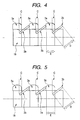
- an arbitrary stirring member 3a and a stirring member 3b adjacent to a stirring member 3a on a downstream side in a rotation direction when a rotor is rotated, exist at a position where a trajectory of the stirring member 3a and a trajectory of the stirring member 3b overlap each other.
- the stirring member 3b is conveniently slid in a direction of the stirring member 3a to make the superposition of the stirring member 3a and the stirring member 3b clear. The situation is the same also in FIG. 5 .
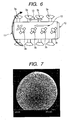
- the shape of a stirring member 3 used in the present invention is not restricted to shapes schematically illustrated in FIGS. 3 , 5 and 6 , and may be, for example, a rectangular shape, a shape having a circular tip end or a paddle-like shape.
- the resin composition particles has a 50% particle diameter (D50) based on volume in the range from 0.2 ⁇ m or more to 6.0 ⁇ m or less and the proportion of particles of 10.0 ⁇ m or more is in an amount of 2.0% by volume or less. It was found that when particle diameters of resin composition particles are set in the above range, residual resin composition particles can be reduced and uniform coating can be conducted.
- D50 particle diameter
- resin composition particles are sandwiched between magnetic carrier core particles and thereby the resin composition particles are flattened.
- pressure is instantaneously applied on the resin composition particles to heat the particles, and thereby a surface of the magnetic carrier core particles is coated therewith.
- heat can be rapidly dissipated; accordingly, the magnetic carriers become difficult to coalesce with each other.
- the resin composition particles of 10.0 ⁇ m or more are flattened with difficulty and less generate heat; accordingly, the resin composition particles are not easily coated with magnetic carrier core particles to remain as the resin composition particles to the last, and thereby the resin composition particles tend to result in forming residual resin composition particles.
- the residual resin composition particles can be reduced.
- the resin composition particles used in the present invention has a 50% particle diameter (D50) based on volume of the resin composition particles preferably in the range from 0.2 ⁇ m or more to 6.0 ⁇ m or less. Furthermore, the D50 of the resin composition particles is more preferable from 0.4 ⁇ m or more to 5.8 ⁇ m or less.
- the 50% particle diameter (D50) based on volume of the resin composition particles is less than 0.2 ⁇ m, the resin composition particles form secondary particles to result in existing as strongly aggregated particles of 10.0 ⁇ m or more. Accordingly, in some cases, layer thickness irregularity may occur on a surface of coated magnetic carrier, particle interfaces may exist, and many residual resin composition particles may remain. Furthermore, when the D50 of the resin composition particles exceeds 6.0 ⁇ m, it is difficult to reduce the residual resin composition particles. Still furthermore, the ability of the carrier to impart charges to a toner cannot be well controlled.
- the proportion of particles of 10.0 ⁇ m or more in the resin composition particles should be 2.0% by volume or less and preferably 1.5% by volume or less. When the proportion exceeds 2.0% by volume, the residual resin composition particles cannot be reduced to result in producing fluctuation in the ability of providing charges to toner.
- the A and the B preferably satisfy a relationship represented by the following formula: 1.1 ⁇ A / B ⁇ 4.0. Furthermore, a relationship represented by the following formula is more preferably satisfied: 1.5 ⁇ A / B ⁇ 3.5.
- the volume (effective processing volume) B means, as illustrated in FIG. 2 , a space volume obtained by subtracting a rotation volume 15 calculated from a trajectory 14 of the stirring member 3 formed by a rotation of the rotor 2 from a volume of the body casing 1.
- peripheral speed of rotation of the rotor 2 has to be increased. Accordingly, it is considered that stirring and mixing tend to be excessive and thereby the magnetic carrier surface is likely to slightly generate cracks and chips. Furthermore, when the peripheral speed of rotation of the rotor 2 is slowed down, uniformity in the coating becomes slightly poor.
- the present invention is characterized in that when an overlapping width of the trajectories is taken as C, and the maximum widths of the stirring member 3a on an upstream side and the stirring member 3b on a downstream side, respectively, are taken as D 3a and D 3b , the overlapping width C and the maximum widths D of the stirring members is preferred to satisfy a relationship represented by the following formulas: 0.05 ⁇ C / D 3 ⁇ a ⁇ 0.50 and 0.05 ⁇ C / D 3 ⁇ b ⁇ 0.50.
- the following formulas are more preferably satisfied: 0.10 ⁇ C / D 3 ⁇ a ⁇ 0.45 and 0.10 ⁇ C / D 3 ⁇ b ⁇ 0.45.
- the overlapping width C of the stirring member 3 is, as illustrated in FIG. 4 , a value obtained by directly overlapping the stirring member 3a and the stirring member 3b and by actually measuring an overlapping width
- the maximum width D of the stirring member 3 is, as illustrated in FIG. 4 , a value obtained by actually measuring a width of the stirring member 3.
- the peripheral speed of rotation of the rotor 2 needs to be slowed down. Accordingly, it is considered that since the stirring and mixing cannot be thoroughly conducted, the residual resin composition particles cannot be sufficiently reduced. Furthermore, when the peripheral speed of rotation of the rotor 2 is increased, cracks and chips are likely to occur slightly on the magnetic carrier surface.
- the C/D that is a relationship of the overlapping width C and the maximum width D of the stirring member 3 can be conveniently controlled by varying a length E of a rotor 18 illustrated in FIGS. 4 and 5 with the maximum width D of the stirring member 3 fixed.
- a temperature T (°C) of a material to be processed that is magnetic carrier core particles and resin composition particles is preferably controlled in a range satisfying the following formula: Tg - 50 ⁇ T ⁇ Tg + 20. (Tg: the glass transition temperature (°C) of a resin component contained in the resin composition particles) Furthermore, Tg - 50 ⁇ T ⁇ Tg + 5 is more preferably satisfied.
- the glass transition temperature (Tg) of a resin component contained in resin composition particles for coating is preferably set to from 70°C or more to 130°C or less and more preferably to from 80°C or more to 120°C or less.
- the temperature T (°C) of a material to be processed during the coating process means an atmospheric temperature inside of the body casing 1 during the coating process, and, specifically, the maximum temperature during the coating process when a thermocouple is attached to an inner wall surface of the body casing 1 from the outside of an apparatus to measure a thermal history during the coating process.
- the temperature T (°C) of a material to be processed during the coating process should be somewhat higher than the glass transition temperature (Tg) of a resin component contained in the resin composition particles. Accordingly, an entire apparatus was heated by causing a heat medium to flow in a jacket disposed inside of a body casing.
- a reason why a processing temperature can be lowered is considered as described below.
- the transportation from the rotor end side surface 10 to the direction of the driver 8 (12) and transportation from the driver 8 to the direction of the rotor end side surface 10 (13) in addition to a collision of an inner wall of body casing 1 and the stirring member 3 with the material to be processed, collisions between materials to be processed each other are effectively and frequently caused.
- heat is instantaneously imparted and a temperature of the material to be processed is locally raised to Tg + 10°C or more.
- heat is not imparted to a region other than the processed region and the temperature of an entire magnetic carrier does not increase. Accordingly, coalescence of magnetic carrier can be suppressed and irregularity of a coated layer caused by disintegration of the coalesced magnetic carrier can be eliminated.
- the rotor 2 to which a cooling medium can be flowed or the body casing 1 provided with the jacket 4 can be preferably used.
- the cooling medium include fluids such as cooling chiller water, hot water, steam, and oil.
- the input amount E of the resin composition particles is, based on 100.0 parts by mass of magnetic carrier core particles, preferably from 0.1 parts by mass or more to 1.0 parts by mass or less and more preferably from 0.2 parts by mass or more to 0.9 parts by mass or less. Furthermore, the input amount E of the resin composition particles and the input amount F of the resin composition particles is preferred to be in a relationship of E ⁇ F.
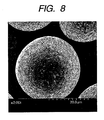
- FIG. 8 illustrates an example of a magnetic carrier produced when a total amount of the resin composition particles is input at once
- FIG. 7 illustrates an example of a magnetic carrier produced when the resin composition particles are input by dividing into two times.
- the number of times of coating with the resin composition particles may be any of two times or more. However, two times is preferable from the economical efficiency point of view.
- an input amount F of the resin composition particles is preferably from 0.5 parts by mass or more to 5.0 parts by mass or less and more preferably from 1.0 part by mass or more to 4.0 parts by mass or less.
- a coating time of a material to be processed is, in the case where an effective process volume of a process space (volume B in FIG. 2 ) is 2.0 ⁇ 10 -3 m 3 , preferably from 2 min or more to 60 min or less.
- an appropriate coating time is obtained at the time of scale-up. For example, 10 minutes in a process time in an apparatus having an effective volume of the process space 9 of 2.0 ⁇ 10 -3 m 3 corresponds to 27 minutes ( ⁇ 10 minutes ⁇ 20 1/3 ) in an apparatus of which effective volume of the process space 9 is scaled-up to 4.0 ⁇ 10 -2 m 3 .
- the power imparted to a material to be processed is preferably from 45% or more to 85% or less of a rated power of the driver 8.
- the power imparted to the material to be processed is preferably from 2.5 kW or more to 4.7 kW or less and when the rating of the driver 8 is 30.0 kW, the power imparted to the material to be processed is preferably from 13.5 kW or more to 25.5 kW or less.
- a peripheral speed of rotation of the stirring member 3 is preferably controlled so that a power of the driver 8 may be in the above range.
- the peripheral speed of rotation is set preferably at from 5 m/sec or more to 30 m/sec or less and more preferably at from 10 m/sec or more to 20 m/sec or less.
- the minimum gap between the body casing 1 and the stirring blade 3 is preferably from 0.5 mm or more to 30.0 mm or less and more preferably from 1.0 mm or more to 20.0 mm or less.
- a magnetic carrier obtained according to the present invention has a 50% particle diameter (D50) based on volume preferably in the range from 20.0 ⁇ m or more to 100.0 ⁇ m or less and more preferably in the range from 25.0 ⁇ m or more to 60.0 ⁇ m or less.
- D50 50% particle diameter
- the 50% particle diameter (D50) based on volume of the magnetic carrier is in the range from 20.0 ⁇ m or more to 100.0 ⁇ m or less, the density of magnetic brush at a development pole is optimized, a charge amount distribution of a toner can be made sharp, high image quality can be achieved, and half-tone image quality can be improved.
- the magnetic carrier core particles used in the present invention has a 50% particle diameter (D50) based on volume preferably in the range from 19.5 ⁇ m or more to 99.5 ⁇ m or less and more preferably in the range from 24.5 ⁇ m or more to 59.5 ⁇ m or less.
- D50 50% particle diameter
- Db/Dc is preferably in a relationship of from 0.002 or more to 0.310 or less.
- the magnetic carrier obtained according to a production method of the present invention has an average circularity preferably of from 0.920 or more to 1.000 or less and more preferably of from 0.950 or more to 1.000 or less from the view point of imparting adequate charges to the toner.
- the magnetic carrier of the present invention preferably has, in a distribution of circularity based on the number, 10.0% by number or less of the magnetic carrier particles having a circularity of 0.900 or less from the viewpoint that even after the magnetic carrier is left under a high temperature and high humidity environment, the ability of imparting charges to the toner can be inhibited from deteriorating.
- the magnetic carrier having a circularity of 0.900 or less in the distribution of circularity is amorphous particles, in particular, particles generated from cracks, chips, aggregation or the like, roughly means a magnetic carrier which does not undergo uniform coating processing.
- the magnetic carrier core particles include magnetic ferrite particles containing one kind or two kinds or more selected from iron, lithium, beryllium, magnesium, calcium, rubidium, strontium, nickel, cobalt, manganese, chromium and titanium, or magnetite particles.
- Preferable examples include magnetite particles or ferrite particles containing at least one kind or two kinds or more selected from manganese, calcium, lithium and magnesium.
- the ferrite particles include particles of iron-based oxides such as Ca-Mg-Fe-based ferrite, Li-Fe-based ferrite, Mn-Mg-Fe-based ferrite, Ca-Be-Fe-based ferrite, Mn-Mg-Sr-Fe-based ferrite, Li-Mg-Fe-based ferrite, Li-Ca-Mg-Fe-based ferrite and Li-Mn-Fe-based ferrite.
- iron-based oxides such as Ca-Mg-Fe-based ferrite, Li-Fe-based ferrite, Mn-Mg-Fe-based ferrite, Ca-Be-Fe-based ferrite, Mn-Mg-Sr-Fe-based ferrite, Li-Mg-Fe-based ferrite, Li-Ca-Mg-Fe-based ferrite and Li-Mn-Fe-based ferrite.
- the ferrite can be obtained in such a manner that oxides, carbonates or nitrates of the respective metals are mixed in a wet form or a dry form, followed by calcining so that a desired ferrite composition may be obtained. Then, the resulting ferrite particles are pulverized to sub-micrometer. To the pulverized ferrite particles, from 20% by mass or more to 50% by mass or less of water and from 0.1% by mass or more to 10% by mass or less of, for example, polyvinyl alcohol (molecular weight: from 500 or more to 10,000 or less) as a binder resin are added to prepare a slurry. The slurry is granulated by the use of a spray dryer or the like and calcined to obtain a ferrite core.
- a ferrite core can be obtained also by polymerizing under the presence of a magnetic material a monomer for forming a binder resin for a magnetic material dispersion type resin carrier core.
- monomers for forming the binder resin include what are described below.
- vinyl monomer, bisphenols and epichlorohydrin used for forming epoxy resins
- phenols and aldehydes used for forming phenol resins
- urea and aldehydes used for forming urea resins, and melamine and aldehydes.
- a method of polymerizing phenol resins from phenols and aldehydes is particularly preferred.
- a magnetic material and phenols and aldehydes are added to an aqueous medium to polymerize the phenols and aldehydes in an aqueous medium in the presence of a basic catalyst, and thereby, a magnetic material dispersion type resin carrier core can be produced.
- Example of magnetic materials used in the magnetic material dispersion type resin carrier core include magnetite particles and ferrite particles and its particle diameter is preferred to be from 0.02 ⁇ m or more to 2.00 ⁇ m or less.
- the resin composition particles used in the present invention to coat a surface of magnetic carrier core will be described.
- the resin composition particles used in the present invention contains at least a resin component.
- a resin component a thermoplastic resin is used.
- the resin component may be one kind of resin or a combination of two kinds or more of resins.
- thermoplastic resins as the resin component examples include polystyrene; acrylic resins such as polymethyl methacrylate and styrene-acrylic acid copolymer; a styrenebutadiene copolymer; an ethylene-vinyl acetate copolymer; polyvinyl chloride; polyvinyl acetate; a polyvinylidene fluoride resin; a fluorocarbon resin; a perfluorocarbon resin; a solvent-soluble perfluorocarbon resin; polyvinyl alcohol; polyvinyl acetal; polyvinyl pyrrolidone; a petroleum resin; cellulose; cellulose derivates such as cellulose acetate, cellulose nitrate, methyl cellulose, hydroxy methyl cellulose, hydroxy methyl cellulose, and hydroxy propyl cellulose; a novolac resin; low molecular-weight polyethylene; polyester resins such as a saturated alkyl polyester resin, polyethylene terephthalate, poly
- a tetrahydrofuran (THF)-soluble matter of a resin component contained in the resin composition particles has preferably a weight average molecular weight Mw of from 15,000 or more to 2,000,000 or less from the viewpoint of adhesiveness with a magnetic carrier core and capability of uniformly coating the surface of the magnetic carrier core particularly during coating. More preferably, the weight average molecular weight is from 50,000 or more to 700,000 or less.
- Examples of methods of producing the resin composition particles include methods directly obtaining particles by suspension polymerization, emulsion polymerization and the like, and a method in which after particles are synthesized by solution polymerization, with the solution being removed by spray drying or the like, particles are prepared.
- microparticles having a number average particle diameter (D1) from 0.01 ⁇ m or more to 3.00 ⁇ m or less may be added. This is because such particles intervene between electrophotographic carrier core particles when a surface of electrophotography carrier core particles is coated with a resin component to exert a spacer effect to excellently control the coalescence of photographic carrier particles, and thereby coating uniformity can be more improved.
- the microparticles contained in the resin composition particles may be microparticles of any of organic materials and inorganic materials.
- crosslinked resin microparticles and inorganic microparticles having strength capable of maintaining a shape of microparticles upon coating are preferred.
- crosslinked resins that form crosslinked resin microparticles include a crosslinked polymethyl methacrylate resin, a crosslinked polystyrene resin, a melamine resin, a guanamine resin, a urea resin, a phenol resin and a nylon resin.
- examples of inorganic microparticles include magnetite, hematite, silica, alumina, and titania.
- the inorganic microparticles are preferred from the viewpoint of acceleration of imparting charges to toner, a decrease in charge-up and an improvement in releasability off the toner. Furthermore, a shape of microparticles is preferred to be spherical to obtain the spacer effect during coating process.
- volume resistance is preferred to be 1 ⁇ 10 6 ⁇ cm or more.
- the resin composition particles may further contain conductive microparticles.
- the conductive microparticles has a volume resistance preferably of 1 ⁇ 10 8 ⁇ cm or less and more preferably of from 1 ⁇ 10 -6 ⁇ cm or more to less than 1 ⁇ 10 6 ⁇ cm.
- the conductive microparticles include carbon black microparticles, graphite microparticles, zinc oxide microparticles and tin oxide microparticles.
- carbon black microparticles are particularly preferred. These conductive microparticles, because of good conductivity thereof, can appropriately control specific resistance of the electrophotographic carrier even when the microparticles are added in a small amount.
- Known toners can be used as a toner that is mixed with a magnetic carrier of the present invention and used. Any of toners produced by any of a pulverizing method, a polymerization method, an emulsion aggregation method, a dissolution suspension method and the like can be used.
- the glass transition temperature (Tg) of resin composition particles is measured with a differential scanning calorimeter (trade name: Q1000, manufactured by TA Instruments Ltd.) according to ASTM D3418-82.
- Melting temperatures of indium and zinc are used to calibrate temperatures of an apparatus detector and heat of fusion of indium is used to calibrate calorie.
- a particle diameter distribution is measured by installing a dry measurement sample feeder (trade name: One-shot dry Sample Conditioner Turbotrac, manufactured by Nikkiso Co., Ltd.) to a laser diffraction/scattering type particle diameter analyzer (trade name: MICROTRACK MT3300EX, manufactured by Nikkiso Co., Ltd.) .
- a dust collector is used as a vacuum source, an air flow is set at 33 L/sec and pressure is set at 17 kPa.
- the control of the measurement is automatically conducted on a software program.
- a 50% particle diameter (D50) that is a cumulated value based on volume is obtained as a particle diameter and the content of particles of 10.0 ⁇ m or more is determined.
- the control and analysis are conducted by the use of an accessory soft (version 10.3.3-202D).
- the measurement conditions are as follows. SetZero time: 10 seconds, measurement time: 10 seconds, and measurement frequency: one time.
- Particle refractive index is 1.81, a particle shape is non-spherical, a measurement upper limit is set at 1408 ⁇ m and a measurement lower limit is set at 0.243 ⁇ m.
- a measurement is conducted under a normal temperature and normal humidity (23°C and 50% RH) environment.
- a molecular weight distribution of a tetrahydrofuran (THF)-soluble matter of resin component contained in resin composition particles is measured by gel permeation chromatography (GPC) as shown below.
- the resin composition particles are dissolved in tetrahydrofuran (THF) over 24 hours at 23°C.
- THF tetrahydrofuran
- the resulting solution is filtered with a solvent-resistant membrane filter having a pore diameter of 0.2 ⁇ m (trade name: MAESHORI DISK, manufactured by Tosoh Corporation) to obtain a sample solution.
- the sample solution is adjusted so that a concentration of a THF-soluble component may be 0.8% by mass.
- a molecular weight calibration curve prepared using standard polystyrene resins is used.
- the standard polystyrene resins specifically include TSK Standard Polystyrenes F-850, F-450, F-288, F-128, F-80, F-40, F-20, F-10, F-4, F-2, F-1, A-5000, A-2500, A-1000 and A-500 (trade name, manufactured by Tosoh Corporation).
- Average circularities of magnetic carrier cores and magnetic carriers and a proportion of magnetic carriers having a circularity of 0.900 or less are measured with a flow-type particle image analyzer "FPIA-3000" (trade name, manufactured by Sysmex Corporation) under the following analysis conditions.
- standard latex particles for example, 5200A (trade name, manufactured by Duke Scientific Co.) diluted with ion exchanged water
- a dispersion solution for measurement is prepared.
- a surfactant preferably, alkyl benzene sulfonate is added, followed by adding 0.3 g of a measurement sample.
- W (such as "VS-150” (trade name, manufactured by VELVO CLEAR Co., Ltd.)) is used for dispersion for 2 minutes to prepare a dispersion solution for measurement.
- the flow-type particle image analyzer mounted with a standard objective lens (at a magnification of 10) is used to measure average circularities of magnetic carrier cores and magnetic carriers, the dispersion liquid prepared according to the above-mentioned procedure is introduced into the flow-type particle image analyzer, and 500 magnetic carrier cores and magnetic carriers are measured according to the total count mode of an HPF measurement mode.
- the average circularities of magnetic carrier cores and magnetic carriers are obtained.
- the flow-type particle image analyzer mounted with a standard objective lens (at a magnification of 10) is used also to measure the proportion of particles of magnetic carriers having a circularity of 0.900 or less, a dispersion liquid prepared according to the above-mentioned procedure is introduced into the flow-type particle image analyzer, and 500 magnetic carriers are measured according to the total count mode of an HPF measurement mode.
- the measurement conditions firstly, with a binarization threshold at the time of particle analysis set to 85%, with a circle equivalent diameter based on the number, with the particle diameter limit set to from 19.92 ⁇ m or more to 200.00 ⁇ m or less and with the shape limit set to from 0.20 or more to 0.90 or less, magnetic carriers are measured to obtain the number of particles having a circularity of 0.900 or less of the magnetic carriers.
- the circle equivalent diameter based on the number with the particle diameter limit set to from 19.92 ⁇ m or more to 200.00 ⁇ m or less as before and with the shape limit set to from 0.20 or more to 1.00 or less, the number of particles of the magnetic carriers having a circularity of 1.00 or less is obtained.
- the flow-type particle image analyzer mounted with a standard objective lens (at a magnification of 10) is used also in the measurement of residual resin composition particles in the magnetic carrier, a dispersion liquid prepared according to the above-mentioned procedure is introduced into the flow-type particle image analyzer, and 500 magnetic carriers are measured according to the total count mode of an HPF measurement mode.
- the magnetic carriers are measured to obtain the abundance ratio of particles present within the particle diameter limits and this is regarded as the residual resin composition particles.
- Magnetite particles (number-average particle diameter: 0.3 ⁇ m) and a silane coupling agent (3-(2-aminoethylaminopropyl)trimethoxysilane) were introduced into a vessel. At that time, the silane coupling agent was introduced so as to be in an amount of 3.0% by mass based on the mass of the magnetite particles. In the vessel, high-speed mixing/stirring was conducted at 110°C to treat the surface of the magnetite particles.
- silane coupling agent 3-(2-aminoethylaminopropyl)trimethoxysilane
- the foregoing materials 5 parts by mass of 28% by mass ammonia water and 25 parts by mass of water were input in a flask, followed by, under mixing, heating up to 85°C over 30 minutes followed by keeping there, further followed by polymerizing for 3 hours to cure. Thereafter, the resultant was cooled to 30°C, after water was further added, a supernatant liquid was removed, a precipitate was washed with water, followed by drying in air. Then, the precipitate was dried at a temperature of 60°C under reduced pressure (5 hPa or less) and thereby magnetic microparticle dispersed magnetic carrier core a where the magnetite particles are dispersed in the phenol resin was obtained.
- the resulting magnetic carrier core a had a 50% particle diameter (D50) based on volume of 37.2 ⁇ m. Furthermore, the average circularity thereof was 0.970 and the proportion of particles having a circularity of 0.900 or less was 4.0% by number.
- the above-mentioned respective materials were wet-mixed, followed by calcining at 900°C for 2 hours, further followed by pulverizing the calcined ferrite composition with a ball mill.
- the resulting pulverized material had a number average particle diameter of 0.8 ⁇ m.
- water 300 parts by mass based on the pulverized material
- polyvinyl alcohol having a weight average molecular weight of 5,000 (3 parts by mass based on the pulverized material) were added, followed by granulating with a spray dryer.
- the granulated material was sintered at 1300°C for 6 hours in an electric furnace under a nitrogen atmosphere having an oxygen concentration of 2.0%, followed by pulverizing, further followed by classifying, thereby magnetic carrier core b having a Mn-Mg-Sr-Fe ferrite composition was obtained.
- the resulting magnetic carrier core b had a 50% particle diameter (D50) based on volume of 42.3 ⁇ m.
- the average circularity thereof was 0.950 and the proportion of particles having a circularity of 0.900 or less was 6.0% by number.
- magnetic carrier core c was obtained in a manner similar to the magnetic carrier core a except that the 28% by mass ammonia water was changed to 7 parts and the water was changed to 40 parts by mass.
- the resulting magnetic carrier core c has a 50% particle diameter (D50) based on volume of 26.3 ⁇ m. Furthermore, the average circularity thereof was 0.964 and the proportion of particles having a circularity of 0.900 or less was 6.1% by number.
- Magnetic carrier core d was obtained in a manner similar to the magnetic carrier core b except that the amount of water added during granulation was changed to 250 parts by mass based on the pulverized material and the amount of polyvinyl alcohol was changed to 1.5 parts by mass based on the pulverized material.
- the resulting magnetic carrier core d had a 50% particle diameter (D50) based on volume of 57.9 ⁇ m. Furthermore, the average circularity thereof was 0.954 and the proportion of particles having a circularity of 0.900 or less was 5.1% by number.
- the resulting resin composition particles were micropulverized by a crusher, thereby producing micropulverized particles having a 50% particle diameter (D50) based on volume of 8.1 ⁇ m and containing 17.8% by volume of particles having a particle diameter of 10.0 ⁇ m or more.
- the resulting micropulverized particles were classified by an air flow classifier and thereby resin composition particles 1 having a 50% particle diameter (D50) based on volume of 1.5 ⁇ m and containing 0.1% by volume of particles having a particle diameter of 10.0 ⁇ m or more were obtained.
- D50 50% particle diameter
- the resulting resin composition particles 1 had a weight average molecular weight (Mw) of 51,000 and the resin component contained had a glass transition temperature (Tg) of 98.0°C.
- Resin composition particles 2 to 6 having particle diameters such as shown in Table 1 were obtained in a manner similar to Production example 1 except that classifying condition for the micropulverized particles was changed.
- the resulting polymer latex had a pH of 6.5.
- the resulting polymer latex was filtered with a 400-mesh metal net, followed by drying the latex with a spray dryer, further followed by pulverizing by a jet mill, thereby producing resin composition particles 7 having a 50% particle diameter (D50) based on volume of 0.9 ⁇ m and containing 0.0% by volume of particles having a particle diameter of 10.0 ⁇ m or more.
- D50 50% particle diameter
- Resin composition particles 8 and 9 having particle diameters shown in Table 1 were obtained in a manner similar to Production example 7 except that the disintegration condition by a jet mill was changed.
- the monomer composition was input, under a nitrogen atmosphere at a temperature of 60°C, stirred at 15,000 rpm for 10 minutes by the TK TYPE HOMOMIXER, followed by granulating the monomer composition. Thereafter, while stirring with a paddle stirring blade, a temperature was raised to 80°C and a reaction was conducted for 10 hours. After the polymerization reaction was completed, a residual monomer was distilled away under reduced pressure, followed by, after cooling, filtering, washing with water and drying, thereby obtaining resin composition particles 10 having a 50% particle diameter (D50) based on volume of 1.9 ⁇ m and containing 0.0% by volume of particles having a particle diameter of 10.0 ⁇ m or more.
- D50 50% particle diameter
- the resulting emulsion had an average particle diameter of 0.19 ⁇ m.
- a residual monomer was distilled away under reduced pressure, followed by, after cooling, filtering, washing with water and drying, thereby obtaining resin composition particles 11 having a 50% particle diameter (D50) based on volume of 0.2 ⁇ m and containing 0.0% by volume of particles having a particle diameter of 10.0 ⁇ m or more.
- Polyester resin peak molecular weight Mp: 6,500, Tg: 65°C
- C.I. Pigment Blue 15:3 5.0 parts by mass
- Paraffin wax melting point: 75°C
- Aluminum compound of 3,5-di-t-butyl salicylic acid 0.5 parts by mass
- the resulting toner particles had a 50% particle diameter (D50) based on volume of 6.5 ⁇ m.
- Micropowder of anatase titanium oxide (specific surface area by BET: 80 m 2 /g, treated with 12% by mass of isobutyltrimethoxysilane): 1.0 parts by mass
- Oil-processed silica (specific surface area by BET: 95 m 2 /g, treated with 15% by mass of silicone oil): 1.5 parts by mass
- Sol-gel method spherical silica (treated with hexamethylsilazane, specific surface area by BET: 24 m 2 /g, number-average particle diameter: 0.1 ⁇ m): 1.5 parts by mass
- an apparatus provided with a cylindrical body casing 1 having an inner diameter of 130 mm and a driver 8 having a rating power of 5.5 kW was used for coating. Furthermore, materials and a production method shown below were used to produce a magnetic carrier.
- a volume A of the magnetic carrier core a and resin composition particles, which are materials to be processed was set to 5.7 ⁇ 10 -4 m 3 and a volume B thereof was set to 2.7 ⁇ 10 -4 m 3 , and thereby A/B was set to 2.1.
- the maximum width D of the stirring member 3 was set to 25.0 mm and a length of the rotor 18 constituting the rotor 2 was controlled, thereby an overlapping width C of the stirring member 3a and the stirring member 3b was set to 4.3 mm and C/D 3a and C/D 3b were set to 0.17.
- a processing time was set to 10 minutes and a peripheral speed of the outermost end of the stirring member 3 was controlled to 11 m/sec so that the power of the driver 8 may be constant at 3.5 kW.
- the resulting magnetic carrier was subjected to magnetic concentration, coarse particles were separated by a circular vibration sifter equipped with a screen having a diameter of 500 mm and an aperture of 75 ⁇ m, and thereby a magnetic carrier 1 was obtained.
- the resulting magnetic carrier 1 had an average circularity of 0.975, the proportion of a magnetic carrier having a circularity of 0.900 or less was 0.2% by number and the residual resin composition particles in the magnetic carrier was 0.5% by volume.
- Processing conditions for the magnetic carrier 1 are shown in Table 2.
- the magnetic carrier 1 was evaluated according to criteria shown below and evaluation results are shown together with physical properties of the magnetic carrier in Table 3.
- the resulting magnetic carrier was observed with an electron microscope (SEM) at a magnification of 2,000 times so that an entire magnetic carrier may be in one viewing field. This observation was repeated 15 times and the surface state of the magnetic carrier was evaluated according to the following evaluation criteria. Evaluation C or more satisfies a practical level in the present invention.
- a full-color copier IRC3220N (trade name, manufactured by Canon Inc.) was used.
- the two-component developer was charged in a developing unit at a cyan site to form an image, followed by conducting the following evaluations. Evaluation results are shown in Table 3.
- Vd1 charge potential of a photosensitive member was controlled so that a developed amount of the toner on the photosensitive member may be 0.6 g/cm 2 .
- the charge potential of the photosensitive member is a value reflecting a charge amount of the toner and can be regarded as an indicator of the charge-imparting ability of the magnetic carrier.
- Vd charge potential
- the toner was quantitatively replenished so that a toner concentration may be constant, 10,000 image were output, and an image density was measured after 10,000 images were output.
- the image density As the image density, a solid image was output, the density was measured with a densitometer X-Rite 500, and an image density was obtained by averaging data of 6 points. With the initial image density taken as D1 and the image density after 10,000 image output as D10, a variation rate of image density, D10/D1, was calculated, followed by evaluating according to the following criteria.
- evaluation C or higher satisfies a practical level in the present invention.
- evaluation C or more satisfies a practical level in the present invention.
- the leakage means a phenomenon where, when the toner coverage on a surface of the magnetic carrier is reduced, charges move from a development bearing member to a photosensitive member surface via the magnetic carrier.
- a leakage mark (a place where a toner layer disappears to be able to see a photosensitive member) appears on a toner layer on a photosensitive member or when the leakage is remarkable, a leakage mark (a place where a void is generated) appears also on a solid image.
- a development device was taken outside an apparatus and left under an environment of 40°C and 90% RH for 72 hours, followed by again installing the development device into an image forming apparatus, further followed by measuring the charge amount Q/M per unit mass on the photosensitive member.
- a maintenance rate of Q/M on the photosensitive member after leaving for 72 hours was calculated and determined based on the following criteria.
- evaluation C or above satisfies a practical level in the present invention.
- Magnetic carriers were prepared in a manner similar to Example 1 except that the conditions were changed to the conditions shown in Table 2. As the result that the power of a driver 8 was controlled so as to be constant at 3.5 kW, a peripheral speed of the stirring member became a value shown in Table 2.
- an overlapping width C of the stirring member 3a and the stirring member 3b was set to 4.3 mm and C/D 3a and C/D 3b were set to 0.17.
- the coating was conducted by adding 0.5 parts by mass of resin composition particles 1 as a first input amount (input amount E) to 100.0 parts by mass of magnetic carrier core a.
- a processing time was set to 10 minutes and a peripheral speed of the outermost end of the stirring member 3 was adjusted to 11 m/sec.
- the coating conditions are shown in Table 2.
- the resulting magnetic carrier was subjected to magnetic concentration and a circular vibration sifter equipped with a screen having a diameter of 500 mm and an aperture of 75 ⁇ m was used to separate coarse particles, thereby a magnetic carrier was obtained.
- the resulting magnetic carrier had an average circularity of 0.977 and the proportion of magnetic carrier having a circularity of 0.900 or less was 0.1% by number.
- the residual resin composition particles in the magnetic carriers was in an amount of 0.2% by volume.
- Magnetic carriers were prepared in a manner similar to Example 17 except that the conditions were changed to the conditions shown in Table 2.
- Magnetic carriers were prepared in a manner similar to Example 17 except that the magnetic carrier core a was changed to magnetic carrier cores b, c and d and furthermore the conditions were changed to the conditions shown in Table 2.
- Magnetic carriers were prepared in a manner similar to Example 17 except that the resin composition particles 1 were changed to resin composition particles 10, 11 and furthermore conditions were changed to conditions shown in Table 2.
- a high-speed stirring mixer (trade name: HIGH-FLEX-GRAL LFS-GS-2J, manufactured by Fukae Powtec Co., Ltd.) was used for coating.
- oil was flowed as a heat medium to a jacket disposed outside of a body casing of the high-speed stirring mixer for heating so that the inside of the body casing may be 108°C, followed by stirring for 10 minutes at the peripheral speed of the outermost end of the stirring member of 11 m/sec.
- the resulting magnetic carriers were subjected to magnetic concentration and a circular vibration sifter equipped with a screen having a diameter of 500 mm and an aperture of 75 ⁇ m was used to separate coarse particles, thereby a magnetic carrier was obtained.
- the resulting magnetic carrier had an average circularity of 0.941 and the proportion of magnetic carriers having a circularity of 0.900 or less was 18.8% by number.
- the residual resin composition particles in the magnetic carriers was in an amount of 14.3% by volume.
- the resulting carrier was evaluated in a manner similar to Example 1. Evaluation results are shown in Table 3.
- Magnetic carriers were prepared in a manner similar to Example 1 except that the conditions were changed to the conditions shown in Table 2. As the result that the power of the driver 8 was controlled so as to be constant at 3.5 kW, a peripheral speed of the stirring member became a value described in Table 2.
- Example 2 Resin composition particles Magnetic core particles Coated amount (parts by mass) Coating time (min) Peripheral speed of the outermost end of stirring member (m/s) Temperature of a material to be processed (°C) A ( ⁇ 10 - 4 m 3 ) B ( ⁇ 10 - 4 m 3 ) A/B C (mm) D (mm) C/D
- Example 1 1 a 1.5 10 11 58 5.7 2.7 2.1 4.3 25.0 0.17
- Example 2 1 a 1.5 10 7 66 5.7 2.7 2.1 12.5 25.0 0.50
- Example 3 1 a 1.5 10 19 42 5.7 2.7 2.1 1.3 25.0 0.05
- Example 4 2 a 1.5 10 11 58 5.7 2.7 2.1 4.3 25.0 0.17
- Example 5 3 a 1.5 10 11 58 5.7 2.7 2.1 4.3 25.0 0.17
- Example 6 4 a 1.5 10 11 58 5.7 2.7 2.1 4.3 25.0 0.17
Landscapes
- Physics & Mathematics (AREA)
- General Physics & Mathematics (AREA)
- Chemical & Material Sciences (AREA)
- Spectroscopy & Molecular Physics (AREA)
- Crystallography & Structural Chemistry (AREA)
- Chemical Kinetics & Catalysis (AREA)
- Developing Agents For Electrophotography (AREA)
Claims (4)
- Procédé pour produire un support magnétique, comprenant l'étape consistant à recouvrir une surface de particules à noyau de support magnétique avec des particules de composition de résine par une force d'impact mécanique pour produire un support magnétique recouvert avec une composition de résine, dans lequel :le revêtement est réalisé à l'aide d'un appareil de revêtement comprenant un rotor ayant au moins une pluralité d'éléments d'agitation sur sa surface, un dispositif d'entraînement pour entraîner le rotor par rotation, et un carter formant corps disposé avec un espace à partir des éléments d'agitation ;les particules de composition de résine ont un diamètre particulaire de 50% (D50) basé sur le volume allant de 0,2 µm ou plus à 6,0 µm ou moins et la proportion des particules de 10,0 µm ou plus est de 2,0% par volume ou moins ; etles particules à noyau de support magnétique et les particules de composition de résine entrées dans l'appareil de revêtement sont, grâce à la rotation du rotor, transportées par une partie des éléments d'agitation dans une direction du dispositif d'entraînement qui est une direction d'une direction axiale du rotor et transportées par une autre partie des éléments d'agitation dans une direction inverse du dispositif d'entraînement qui est une direction inverse à la direction axiale du rotor, suivi par, tout en réalisant, de manière répétée, le transport dans la direction du dispositif d'entraînement et le transport dans la direction inverse du dispositif d'entraînement, le revêtement de la surface des particules à noyau de support magnétique avec les particules de composition de résine.
- Procédé pour produire un support magnétique selon la revendication 1, dans lequel, lorsque le volume total des particules à noyau de support magnétique et des particules de composition de résine entrées dans l'appareil de revêtement est considéré comme étant A, un espace minimum entre une surface périphérique interne du carter formant corps et l'élément d'agitation est considéré comme étant d, et le volume d'un espace cylindrique ayant une épaisseur d vers une direction centrale par rapport à la surface périphérique interne du carter formant corps est considéré comme étant B, le A et le B satisfont une relation représentée par la formule suivante :

- Procédé pour produire un support magnétique selon la revendication 1 ou 2, dans lequel, pour un élément d'agitation arbitraire 3a et un élément d'agitation 3b adjacent à l'élément d'agitation 3a sur un côté en aval dans une direction de rotation, lorsque le rotor est entraîné en rotation, une trajectoire de l'élément d'agitation 3a et une trajectoire de l'élément d'agitation 3b se chevauchent, lorsqu'une largeur de chevauchement des trajectoires est considérée comme étant C et les largeurs minimales des éléments d'agitation respectifs sont considérées comme étant D3a et D3b, la largeur de chevauchement C et les largeurs maximales D des éléments d'agitation satisfont une relation représentée par les formules suivantes :

et
- Support magnétique produit selon un procédé selon l'une quelconque des revendications 1 à 3.
Applications Claiming Priority (3)
| Application Number | Priority Date | Filing Date | Title |
|---|---|---|---|
| JP2009146230A JP4766713B2 (ja) | 2009-06-19 | 2009-06-19 | 磁性キャリアの製造方法 |
| JP2009146235A JP5361558B2 (ja) | 2009-06-19 | 2009-06-19 | 磁性キャリアの製造方法及び該製造方法を用いて製造した磁性キャリア |
| PCT/JP2010/003894 WO2010146814A1 (fr) | 2009-06-19 | 2010-06-11 | Procédé de fabrication d'un support magnétique et support magnétique obtenu à l'aide de ce procédé |
Publications (3)
| Publication Number | Publication Date |
|---|---|
| EP2444848A1 EP2444848A1 (fr) | 2012-04-25 |
| EP2444848A4 EP2444848A4 (fr) | 2013-09-18 |
| EP2444848B1 true EP2444848B1 (fr) | 2014-11-12 |
Family
ID=43356147
Family Applications (1)
| Application Number | Title | Priority Date | Filing Date |
|---|---|---|---|
| EP10789197.0A Not-in-force EP2444848B1 (fr) | 2009-06-19 | 2010-06-11 | Procédé de fabrication d'un support magnétique et support magnétique obtenu à l'aide de ce procédé |
Country Status (5)
| Country | Link |
|---|---|
| US (1) | US8323726B2 (fr) |
| EP (1) | EP2444848B1 (fr) |
| KR (1) | KR101396011B1 (fr) |
| CN (1) | CN102804080B (fr) |
| WO (1) | WO2010146814A1 (fr) |
Families Citing this family (53)
| Publication number | Priority date | Publication date | Assignee | Title |
|---|---|---|---|---|
| CN103140806B (zh) | 2010-09-16 | 2015-11-25 | 佳能株式会社 | 调色剂 |
| JP5865032B2 (ja) | 2010-11-29 | 2016-02-17 | キヤノン株式会社 | トナー |
| WO2012086524A1 (fr) | 2010-12-24 | 2012-06-28 | Canon Kabushiki Kaisha | Toner |
| US8974994B2 (en) | 2012-01-31 | 2015-03-10 | Canon Kabushiki Kaisha | Magnetic carrier, two-component developer, and developer for replenishment |
| US9063443B2 (en) | 2012-05-28 | 2015-06-23 | Canon Kabushiki Kaisha | Magnetic carrier and two-component developer |
| US9058924B2 (en) | 2012-05-28 | 2015-06-16 | Canon Kabushiki Kaisha | Magnetic carrier and two-component developer |
| JP6012328B2 (ja) | 2012-08-01 | 2016-10-25 | キヤノン株式会社 | 磁性キャリアの製造方法 |
| WO2015016384A1 (fr) | 2013-07-31 | 2015-02-05 | Canon Kabushiki Kaisha | Toner magnétique |
| US9715188B2 (en) | 2013-07-31 | 2017-07-25 | Canon Kabushiki Kaisha | Toner |
| US9915885B2 (en) | 2015-05-13 | 2018-03-13 | Canon Kabushiki Kaisha | Toner |
| US9969834B2 (en) | 2015-08-25 | 2018-05-15 | Canon Kabushiki Kaisha | Wax dispersant for toner and toner |
| JP6592336B2 (ja) * | 2015-11-13 | 2019-10-16 | コニカミノルタ株式会社 | 静電潜像現像用キャリアの製造方法及び二成分現像剤の製造方法 |
| US9897932B2 (en) | 2016-02-04 | 2018-02-20 | Canon Kabushiki Kaisha | Toner |
| US10012918B2 (en) | 2016-02-19 | 2018-07-03 | Canon Kabushiki Kaisha | Toner and method for producing toner |
| JP6700878B2 (ja) | 2016-03-16 | 2020-05-27 | キヤノン株式会社 | トナー及びトナーの製造方法 |
| JP2017181575A (ja) * | 2016-03-28 | 2017-10-05 | 富士ゼロックス株式会社 | 二成分現像剤用キャリア及びその製造方法、二成分現像剤、画像形成方法、並びに、画像形成装置 |
| US10133201B2 (en) | 2016-08-01 | 2018-11-20 | Canon Kabushiki Kaisha | Toner |
| JP6921678B2 (ja) | 2016-08-16 | 2021-08-18 | キヤノン株式会社 | トナー製造方法及び重合体 |
| JP6750871B2 (ja) | 2016-08-25 | 2020-09-02 | キヤノン株式会社 | トナー |
| JP6900279B2 (ja) | 2016-09-13 | 2021-07-07 | キヤノン株式会社 | トナー及びトナーの製造方法 |
| JP7005220B2 (ja) | 2017-08-14 | 2022-01-21 | キヤノン株式会社 | トナー |
| JP7057088B2 (ja) | 2017-10-05 | 2022-04-19 | キヤノン株式会社 | トナー |
| JP7057092B2 (ja) | 2017-10-12 | 2022-04-19 | キヤノン株式会社 | トナー及びトナーの製造方法 |
| JP6965130B2 (ja) | 2017-12-05 | 2021-11-10 | キヤノン株式会社 | マゼンタトナー及びトナーキット |
| JP7237688B2 (ja) | 2018-05-01 | 2023-03-13 | キヤノン株式会社 | トナー |
| EP3582013B1 (fr) | 2018-06-13 | 2023-08-09 | Canon Kabushiki Kaisha | Toner et son procédé de production |
| US10969705B2 (en) | 2018-06-13 | 2021-04-06 | Canon Kabushiki Kaisha | Two-component developer |
| EP3582016B1 (fr) | 2018-06-13 | 2023-10-18 | Canon Kabushiki Kaisha | Toner et développeur à deux composants |
| US10877386B2 (en) | 2018-08-14 | 2020-12-29 | Canon Kabushiki Kaisha | Toner |
| US10775710B1 (en) | 2019-04-22 | 2020-09-15 | Canon Kabushiki Kaisha | Toner |
| JP7327993B2 (ja) | 2019-05-13 | 2023-08-16 | キヤノン株式会社 | トナー及びトナーの製造方法 |
| JP7391572B2 (ja) | 2019-08-29 | 2023-12-05 | キヤノン株式会社 | トナー及びトナーの製造方法 |
| JP7642340B2 (ja) | 2019-10-07 | 2025-03-10 | キヤノン株式会社 | トナー |
| JP7730632B2 (ja) | 2019-11-13 | 2025-08-28 | キヤノン株式会社 | 磁性キャリア、二成分現像剤、及び磁性キャリアの製造方法 |
| JP7543100B2 (ja) | 2019-12-13 | 2024-09-02 | キヤノン株式会社 | トナー及び二成分系現像剤 |
| JP7523901B2 (ja) | 2019-12-13 | 2024-07-29 | キヤノン株式会社 | トナー及びトナーの製造方法 |
| JP7543108B2 (ja) | 2019-12-13 | 2024-09-02 | キヤノン株式会社 | トナー |
| JP7443043B2 (ja) | 2019-12-13 | 2024-03-05 | キヤノン株式会社 | トナー及び二成分系現像剤 |
| US11809131B2 (en) | 2020-03-05 | 2023-11-07 | Canon Kabushiki Kaisha | Toner |
| JP7493963B2 (ja) | 2020-03-05 | 2024-06-03 | キヤノン株式会社 | トナー及びトナーの製造方法 |
| US12099326B2 (en) | 2020-03-31 | 2024-09-24 | Canon Kabushiki Kaisha | Toner |
| JP7651340B2 (ja) | 2020-04-06 | 2025-03-26 | キヤノン株式会社 | トナー及びトナーの製造方法 |
| JP7475982B2 (ja) | 2020-06-19 | 2024-04-30 | キヤノン株式会社 | トナー |
| JP7574015B2 (ja) | 2020-08-14 | 2024-10-28 | キヤノン株式会社 | トナーの製造方法 |
| JP7551409B2 (ja) | 2020-09-10 | 2024-09-17 | キヤノン株式会社 | トナー |
| JP7621769B2 (ja) | 2020-10-23 | 2025-01-27 | キヤノン株式会社 | トナー |
| JP7665311B2 (ja) | 2020-10-23 | 2025-04-21 | キヤノン株式会社 | トナー |
| JP7551449B2 (ja) | 2020-10-23 | 2024-09-17 | キヤノン株式会社 | トナー及びトナーの製造方法 |
| JP7631086B2 (ja) | 2021-05-12 | 2025-02-18 | キヤノン株式会社 | トナー |
| US12276938B2 (en) | 2021-06-21 | 2025-04-15 | Canon Kabushiki Kaisha | Toner |
| JP7799527B2 (ja) | 2022-03-23 | 2026-01-15 | キヤノン株式会社 | トナー |
| US12510838B2 (en) | 2022-03-23 | 2025-12-30 | Canon Kabushiki Kaisha | Toner and two-component developer |
| US12585207B2 (en) | 2022-03-30 | 2026-03-24 | Canon Kabushiki Kaisha | Toner |
Family Cites Families (19)
| Publication number | Priority date | Publication date | Assignee | Title |
|---|---|---|---|---|
| JPH0752310B2 (ja) | 1987-03-24 | 1995-06-05 | コニカ株式会社 | 静電像現像用キャリアの製造方法 |
| JP2702194B2 (ja) * | 1988-12-13 | 1998-01-21 | コニカ株式会社 | 静電像現像用キャリヤおよび製造方法 |
| JP2811079B2 (ja) | 1989-03-29 | 1998-10-15 | コニカ株式会社 | 静電像現像用キャリア及びその製造方法 |
| JP2847679B2 (ja) | 1990-03-20 | 1999-01-20 | コニカ株式会社 | 静電荷像現像用キャリアおよびその製造方法 |
| JPH0484143A (ja) * | 1990-07-27 | 1992-03-17 | Konica Corp | 静電荷像現像用キャリア |
| SE468602B (sv) * | 1990-12-17 | 1993-02-15 | Albany Int Corp | Pressfilt samt saett att framstaella densamma |
| US6484266B2 (en) * | 1995-09-29 | 2002-11-19 | Matsushita Electric Industrial Co., Ltd. | Method and an apparatus for reproducing bitstream having non-sequential system clock data seamlessly therebetween |
| TW436777B (en) * | 1995-09-29 | 2001-05-28 | Matsushita Electric Industrial Co Ltd | A method and an apparatus for reproducing bitstream having non-sequential system clock data seamlessly therebetween |
| CN1866378B (zh) * | 1996-02-28 | 2010-09-29 | 松下电器产业株式会社 | 光盘重放装置 |
| JPH1048891A (ja) * | 1996-08-02 | 1998-02-20 | Canon Inc | コートキャリアの製造方法 |
| EP2175666B1 (fr) * | 1996-12-04 | 2012-11-14 | Panasonic Corporation | Disque optique pour enregistrement en haute qualité et en trois dimensions, appareil de reproduction des disques optiques, et appareil d'enregistrement des disques optiques |
| JP3598449B2 (ja) * | 1997-04-11 | 2004-12-08 | コニカミノルタホールディングス株式会社 | 静電荷像現像用キャリアの製造方法 |
| EP1708487B1 (fr) * | 1997-08-29 | 2013-05-08 | Panasonic Corporation | Procédé et appareil pour la lecture d'une disque vidéo-optique à haute résolution |
| JP4669253B2 (ja) * | 2004-02-23 | 2011-04-13 | ホソカワミクロン株式会社 | 処理装置及び粉体処理方法 |
| JP4358261B2 (ja) * | 2007-06-28 | 2009-11-04 | シャープ株式会社 | トナーおよびトナーの製造方法、2成分現像剤、現像装置ならびに画像形成装置 |
| JP4739316B2 (ja) * | 2007-12-20 | 2011-08-03 | キヤノン株式会社 | 電子写真用キャリアの製造方法及び該製造方法を用いて製造した電子写真用キャリア |
| JP5197024B2 (ja) | 2008-01-09 | 2013-05-15 | 株式会社東芝 | 放射線治療システム、放射線治療支援装置及び放射線治療支援プログラム |
| CN102510464B (zh) * | 2008-09-17 | 2015-04-22 | 松下电器产业株式会社 | 记录方法、再现装置和集成电路 |
| WO2010076846A1 (fr) * | 2008-12-29 | 2010-07-08 | パナソニック株式会社 | Support d'enregistrement, dispositif de reproduction et circuit intégré |
-
2010
- 2010-06-11 EP EP10789197.0A patent/EP2444848B1/fr not_active Not-in-force
- 2010-06-11 WO PCT/JP2010/003894 patent/WO2010146814A1/fr not_active Ceased
- 2010-06-11 KR KR1020127000808A patent/KR101396011B1/ko not_active Expired - Fee Related
- 2010-06-11 CN CN201080027322.5A patent/CN102804080B/zh not_active Expired - Fee Related
- 2010-10-07 US US12/899,957 patent/US8323726B2/en not_active Expired - Fee Related
Also Published As
| Publication number | Publication date |
|---|---|
| US20110024669A1 (en) | 2011-02-03 |
| EP2444848A4 (fr) | 2013-09-18 |
| CN102804080B (zh) | 2014-06-11 |
| KR20120025596A (ko) | 2012-03-15 |
| KR101396011B1 (ko) | 2014-05-16 |
| EP2444848A1 (fr) | 2012-04-25 |
| CN102804080A (zh) | 2012-11-28 |
| WO2010146814A1 (fr) | 2010-12-23 |
| US8323726B2 (en) | 2012-12-04 |
Similar Documents
| Publication | Publication Date | Title |
|---|---|---|
| EP2444848B1 (fr) | Procédé de fabrication d'un support magnétique et support magnétique obtenu à l'aide de ce procédé | |
| US9063443B2 (en) | Magnetic carrier and two-component developer | |
| JP5901257B2 (ja) | 二成分系現像剤の製造方法 | |
| JP7293009B2 (ja) | 磁性キャリア、二成分系現像剤、補給用現像剤、及び画像形成方法 | |
| US9323175B2 (en) | Brilliant toner, electrostatic charge image developer, and toner cartridge | |
| JP7321882B2 (ja) | 磁性キャリア及び二成分系現像剤 | |
| JP2016048369A (ja) | 磁性キャリア及び二成分系現像剤 | |
| JP6659142B2 (ja) | 磁性キャリア、二成分系現像剤、補給用現像剤、及び画像形成方法 | |
| US20130143151A1 (en) | Electrostatic charge image developing toner, electrostatic charge image developer, toner cartridge, process cartridge, image forming apparatus, and image forming method | |
| JP2020027275A (ja) | 磁性キャリア、二成分系現像剤、補給用現像剤、及び画像形成方法 | |
| US9304425B2 (en) | Brilliant toner, electrostatic charge image developer, and toner cartridge | |
| US20150277252A1 (en) | Brilliant toner, electrostatic charge image developer, toner cartridge, and process cartridge | |
| JP2015084050A (ja) | 静電荷像現像剤、現像剤カートリッジ、プロセスカートリッジ、画像形成装置、及び、画像形成方法 | |
| JP5495633B2 (ja) | 磁性キャリア及び二成分系現像剤 | |
| JP5398374B2 (ja) | 磁性キャリアの製造方法及び、その製造方法により製造された磁性キャリア | |
| JP5361558B2 (ja) | 磁性キャリアの製造方法及び該製造方法を用いて製造した磁性キャリア | |
| US12013661B2 (en) | Method for producing carrier for electrostatic charge image development, method for producing electrostatic charge image developer, image forming method, and carrier for electrostatic charge image development | |
| US9239532B2 (en) | Brilliant toner, electrostatic charge image developer, and toner cartridge | |
| JP4766713B2 (ja) | 磁性キャリアの製造方法 | |
| JP7543117B2 (ja) | 二成分系現像剤、補給用現像剤、及び画像形成方法 | |
| US12117769B2 (en) | Method for producing recycled carrier, method for producing recycled electrostatic charge image developer, image forming method, and recycled carrier | |
| JP7387337B2 (ja) | 磁性キャリア、二成分系現像剤、補給用現像剤、及び画像形成方法 | |
| JP2023130751A (ja) | 静電荷像現像用キャリアの製造方法、静電荷像現像剤、画像形成方法、及び、画像形成装置 | |
| JP6914772B2 (ja) | 磁性キャリア、二成分系現像剤、補給用現像剤、及び画像形成方法 | |
| JP2025014913A (ja) | 静電荷像現像用キャリアの製造方法、及び、静電荷像現像剤の製造方法 |
Legal Events
| Date | Code | Title | Description |
|---|---|---|---|
| PUAI | Public reference made under article 153(3) epc to a published international application that has entered the european phase |
Free format text: ORIGINAL CODE: 0009012 |
|
| 17P | Request for examination filed |
Effective date: 20120119 |
|
| AK | Designated contracting states |
Kind code of ref document: A1 Designated state(s): AL AT BE BG CH CY CZ DE DK EE ES FI FR GB GR HR HU IE IS IT LI LT LU LV MC MK MT NL NO PL PT RO SE SI SK SM TR |
|
| DAX | Request for extension of the european patent (deleted) | ||
| A4 | Supplementary search report drawn up and despatched |
Effective date: 20130821 |
|
| RIC1 | Information provided on ipc code assigned before grant |
Ipc: G03G 9/107 20060101ALI20130814BHEP Ipc: G03G 9/113 20060101AFI20130814BHEP |
|
| RIC1 | Information provided on ipc code assigned before grant |
Ipc: G03G 9/107 20060101ALI20140331BHEP Ipc: G03G 9/113 20060101AFI20140331BHEP |
|
| GRAP | Despatch of communication of intention to grant a patent |
Free format text: ORIGINAL CODE: EPIDOSNIGR1 |
|
| INTG | Intention to grant announced |
Effective date: 20140526 |
|
| GRAS | Grant fee paid |
Free format text: ORIGINAL CODE: EPIDOSNIGR3 |
|
| GRAA | (expected) grant |
Free format text: ORIGINAL CODE: 0009210 |
|
| AK | Designated contracting states |
Kind code of ref document: B1 Designated state(s): AL AT BE BG CH CY CZ DE DK EE ES FI FR GB GR HR HU IE IS IT LI LT LU LV MC MK MT NL NO PL PT RO SE SI SK SM TR |
|
| REG | Reference to a national code |
Ref country code: GB Ref legal event code: FG4D |
|
| REG | Reference to a national code |
Ref country code: CH Ref legal event code: EP |
|
| REG | Reference to a national code |
Ref country code: AT Ref legal event code: REF Ref document number: 696095 Country of ref document: AT Kind code of ref document: T Effective date: 20141115 |
|
| REG | Reference to a national code |
Ref country code: IE Ref legal event code: FG4D |
|
| REG | Reference to a national code |
Ref country code: DE Ref legal event code: R096 Ref document number: 602010020230 Country of ref document: DE Effective date: 20141224 |
|
| REG | Reference to a national code |
Ref country code: NL Ref legal event code: VDEP Effective date: 20141112 |
|
| REG | Reference to a national code |
Ref country code: AT Ref legal event code: MK05 Ref document number: 696095 Country of ref document: AT Kind code of ref document: T Effective date: 20141112 |
|
| PG25 | Lapsed in a contracting state [announced via postgrant information from national office to epo] |
Ref country code: NL Free format text: LAPSE BECAUSE OF FAILURE TO SUBMIT A TRANSLATION OF THE DESCRIPTION OR TO PAY THE FEE WITHIN THE PRESCRIBED TIME-LIMIT Effective date: 20141112 Ref country code: PT Free format text: LAPSE BECAUSE OF FAILURE TO SUBMIT A TRANSLATION OF THE DESCRIPTION OR TO PAY THE FEE WITHIN THE PRESCRIBED TIME-LIMIT Effective date: 20150312 Ref country code: FI Free format text: LAPSE BECAUSE OF FAILURE TO SUBMIT A TRANSLATION OF THE DESCRIPTION OR TO PAY THE FEE WITHIN THE PRESCRIBED TIME-LIMIT Effective date: 20141112 Ref country code: ES Free format text: LAPSE BECAUSE OF FAILURE TO SUBMIT A TRANSLATION OF THE DESCRIPTION OR TO PAY THE FEE WITHIN THE PRESCRIBED TIME-LIMIT Effective date: 20141112 Ref country code: NO Free format text: LAPSE BECAUSE OF FAILURE TO SUBMIT A TRANSLATION OF THE DESCRIPTION OR TO PAY THE FEE WITHIN THE PRESCRIBED TIME-LIMIT Effective date: 20150212 Ref country code: LT Free format text: LAPSE BECAUSE OF FAILURE TO SUBMIT A TRANSLATION OF THE DESCRIPTION OR TO PAY THE FEE WITHIN THE PRESCRIBED TIME-LIMIT Effective date: 20141112 Ref country code: IS Free format text: LAPSE BECAUSE OF FAILURE TO SUBMIT A TRANSLATION OF THE DESCRIPTION OR TO PAY THE FEE WITHIN THE PRESCRIBED TIME-LIMIT Effective date: 20150312 |
|
| PG25 | Lapsed in a contracting state [announced via postgrant information from national office to epo] |
Ref country code: GR Free format text: LAPSE BECAUSE OF FAILURE TO SUBMIT A TRANSLATION OF THE DESCRIPTION OR TO PAY THE FEE WITHIN THE PRESCRIBED TIME-LIMIT Effective date: 20150213 Ref country code: CY Free format text: LAPSE BECAUSE OF FAILURE TO SUBMIT A TRANSLATION OF THE DESCRIPTION OR TO PAY THE FEE WITHIN THE PRESCRIBED TIME-LIMIT Effective date: 20141112 Ref country code: HR Free format text: LAPSE BECAUSE OF FAILURE TO SUBMIT A TRANSLATION OF THE DESCRIPTION OR TO PAY THE FEE WITHIN THE PRESCRIBED TIME-LIMIT Effective date: 20141112 Ref country code: SE Free format text: LAPSE BECAUSE OF FAILURE TO SUBMIT A TRANSLATION OF THE DESCRIPTION OR TO PAY THE FEE WITHIN THE PRESCRIBED TIME-LIMIT Effective date: 20141112 Ref country code: AT Free format text: LAPSE BECAUSE OF FAILURE TO SUBMIT A TRANSLATION OF THE DESCRIPTION OR TO PAY THE FEE WITHIN THE PRESCRIBED TIME-LIMIT Effective date: 20141112 Ref country code: PL Free format text: LAPSE BECAUSE OF FAILURE TO SUBMIT A TRANSLATION OF THE DESCRIPTION OR TO PAY THE FEE WITHIN THE PRESCRIBED TIME-LIMIT Effective date: 20141112 Ref country code: LV Free format text: LAPSE BECAUSE OF FAILURE TO SUBMIT A TRANSLATION OF THE DESCRIPTION OR TO PAY THE FEE WITHIN THE PRESCRIBED TIME-LIMIT Effective date: 20141112 |
|
| PG25 | Lapsed in a contracting state [announced via postgrant information from national office to epo] |
Ref country code: CZ Free format text: LAPSE BECAUSE OF FAILURE TO SUBMIT A TRANSLATION OF THE DESCRIPTION OR TO PAY THE FEE WITHIN THE PRESCRIBED TIME-LIMIT Effective date: 20141112 Ref country code: SK Free format text: LAPSE BECAUSE OF FAILURE TO SUBMIT A TRANSLATION OF THE DESCRIPTION OR TO PAY THE FEE WITHIN THE PRESCRIBED TIME-LIMIT Effective date: 20141112 Ref country code: EE Free format text: LAPSE BECAUSE OF FAILURE TO SUBMIT A TRANSLATION OF THE DESCRIPTION OR TO PAY THE FEE WITHIN THE PRESCRIBED TIME-LIMIT Effective date: 20141112 Ref country code: RO Free format text: LAPSE BECAUSE OF FAILURE TO SUBMIT A TRANSLATION OF THE DESCRIPTION OR TO PAY THE FEE WITHIN THE PRESCRIBED TIME-LIMIT Effective date: 20141112 Ref country code: DK Free format text: LAPSE BECAUSE OF FAILURE TO SUBMIT A TRANSLATION OF THE DESCRIPTION OR TO PAY THE FEE WITHIN THE PRESCRIBED TIME-LIMIT Effective date: 20141112 |
|
| REG | Reference to a national code |
Ref country code: DE Ref legal event code: R097 Ref document number: 602010020230 Country of ref document: DE |
|
| PLBE | No opposition filed within time limit |
Free format text: ORIGINAL CODE: 0009261 |
|
| STAA | Information on the status of an ep patent application or granted ep patent |
Free format text: STATUS: NO OPPOSITION FILED WITHIN TIME LIMIT |
|
| 26N | No opposition filed |
Effective date: 20150813 |
|
| PG25 | Lapsed in a contracting state [announced via postgrant information from national office to epo] |
Ref country code: IT Free format text: LAPSE BECAUSE OF FAILURE TO SUBMIT A TRANSLATION OF THE DESCRIPTION OR TO PAY THE FEE WITHIN THE PRESCRIBED TIME-LIMIT Effective date: 20141112 |
|
| PG25 | Lapsed in a contracting state [announced via postgrant information from national office to epo] |
Ref country code: MC Free format text: LAPSE BECAUSE OF FAILURE TO SUBMIT A TRANSLATION OF THE DESCRIPTION OR TO PAY THE FEE WITHIN THE PRESCRIBED TIME-LIMIT Effective date: 20141112 |
|
| REG | Reference to a national code |
Ref country code: CH Ref legal event code: PL |
|
| PG25 | Lapsed in a contracting state [announced via postgrant information from national office to epo] |
Ref country code: SI Free format text: LAPSE BECAUSE OF FAILURE TO SUBMIT A TRANSLATION OF THE DESCRIPTION OR TO PAY THE FEE WITHIN THE PRESCRIBED TIME-LIMIT Effective date: 20141112 Ref country code: LU Free format text: LAPSE BECAUSE OF FAILURE TO SUBMIT A TRANSLATION OF THE DESCRIPTION OR TO PAY THE FEE WITHIN THE PRESCRIBED TIME-LIMIT Effective date: 20150611 |
|
| REG | Reference to a national code |
Ref country code: IE Ref legal event code: MM4A |
|
| PG25 | Lapsed in a contracting state [announced via postgrant information from national office to epo] |
Ref country code: CH Free format text: LAPSE BECAUSE OF NON-PAYMENT OF DUE FEES Effective date: 20150630 Ref country code: IE Free format text: LAPSE BECAUSE OF NON-PAYMENT OF DUE FEES Effective date: 20150611 Ref country code: LI Free format text: LAPSE BECAUSE OF NON-PAYMENT OF DUE FEES Effective date: 20150630 |
|
| REG | Reference to a national code |
Ref country code: FR Ref legal event code: PLFP Year of fee payment: 7 |
|
| PGFP | Annual fee paid to national office [announced via postgrant information from national office to epo] |
Ref country code: GB Payment date: 20160627 Year of fee payment: 7 |
|
| PGFP | Annual fee paid to national office [announced via postgrant information from national office to epo] |
Ref country code: FR Payment date: 20160627 Year of fee payment: 7 |
|
| PGFP | Annual fee paid to national office [announced via postgrant information from national office to epo] |
Ref country code: DE Payment date: 20160630 Year of fee payment: 7 |
|
| PG25 | Lapsed in a contracting state [announced via postgrant information from national office to epo] |
Ref country code: MT Free format text: LAPSE BECAUSE OF FAILURE TO SUBMIT A TRANSLATION OF THE DESCRIPTION OR TO PAY THE FEE WITHIN THE PRESCRIBED TIME-LIMIT Effective date: 20141112 |
|
| PG25 | Lapsed in a contracting state [announced via postgrant information from national office to epo] |
Ref country code: BG Free format text: LAPSE BECAUSE OF FAILURE TO SUBMIT A TRANSLATION OF THE DESCRIPTION OR TO PAY THE FEE WITHIN THE PRESCRIBED TIME-LIMIT Effective date: 20141112 Ref country code: SM Free format text: LAPSE BECAUSE OF FAILURE TO SUBMIT A TRANSLATION OF THE DESCRIPTION OR TO PAY THE FEE WITHIN THE PRESCRIBED TIME-LIMIT Effective date: 20141112 Ref country code: HU Free format text: LAPSE BECAUSE OF FAILURE TO SUBMIT A TRANSLATION OF THE DESCRIPTION OR TO PAY THE FEE WITHIN THE PRESCRIBED TIME-LIMIT; INVALID AB INITIO Effective date: 20100611 |
|
| PG25 | Lapsed in a contracting state [announced via postgrant information from national office to epo] |
Ref country code: TR Free format text: LAPSE BECAUSE OF FAILURE TO SUBMIT A TRANSLATION OF THE DESCRIPTION OR TO PAY THE FEE WITHIN THE PRESCRIBED TIME-LIMIT Effective date: 20141112 |
|
| PG25 | Lapsed in a contracting state [announced via postgrant information from national office to epo] |
Ref country code: BE Free format text: LAPSE BECAUSE OF FAILURE TO SUBMIT A TRANSLATION OF THE DESCRIPTION OR TO PAY THE FEE WITHIN THE PRESCRIBED TIME-LIMIT Effective date: 20141112 |
|
| REG | Reference to a national code |
Ref country code: DE Ref legal event code: R119 Ref document number: 602010020230 Country of ref document: DE |
|
| GBPC | Gb: european patent ceased through non-payment of renewal fee |
Effective date: 20170611 |
|
| REG | Reference to a national code |
Ref country code: FR Ref legal event code: ST Effective date: 20180228 |
|
| PG25 | Lapsed in a contracting state [announced via postgrant information from national office to epo] |
Ref country code: GB Free format text: LAPSE BECAUSE OF NON-PAYMENT OF DUE FEES Effective date: 20170611 Ref country code: DE Free format text: LAPSE BECAUSE OF NON-PAYMENT OF DUE FEES Effective date: 20180103 |
|
| PG25 | Lapsed in a contracting state [announced via postgrant information from national office to epo] |
Ref country code: FR Free format text: LAPSE BECAUSE OF NON-PAYMENT OF DUE FEES Effective date: 20170630 |
|
| PG25 | Lapsed in a contracting state [announced via postgrant information from national office to epo] |
Ref country code: MK Free format text: LAPSE BECAUSE OF FAILURE TO SUBMIT A TRANSLATION OF THE DESCRIPTION OR TO PAY THE FEE WITHIN THE PRESCRIBED TIME-LIMIT Effective date: 20141112 |
|
| PG25 | Lapsed in a contracting state [announced via postgrant information from national office to epo] |
Ref country code: AL Free format text: LAPSE BECAUSE OF FAILURE TO SUBMIT A TRANSLATION OF THE DESCRIPTION OR TO PAY THE FEE WITHIN THE PRESCRIBED TIME-LIMIT Effective date: 20141112 |