EP2446842A1 - Dispositif de stabilisation d'une colonne vertébrale - Google Patents
Dispositif de stabilisation d'une colonne vertébrale Download PDFInfo
- Publication number
- EP2446842A1 EP2446842A1 EP20100013960 EP10013960A EP2446842A1 EP 2446842 A1 EP2446842 A1 EP 2446842A1 EP 20100013960 EP20100013960 EP 20100013960 EP 10013960 A EP10013960 A EP 10013960A EP 2446842 A1 EP2446842 A1 EP 2446842A1
- Authority
- EP
- European Patent Office
- Prior art keywords
- sleeve
- screw
- external thread
- pitch
- figur
- Prior art date
- Legal status (The legal status is an assumption and is not a legal conclusion. Google has not performed a legal analysis and makes no representation as to the accuracy of the status listed.)
- Granted
Links
- 230000003019 stabilising effect Effects 0.000 title 1
- 229910001000 nickel titanium Inorganic materials 0.000 claims abstract description 4
- HLXZNVUGXRDIFK-UHFFFAOYSA-N nickel titanium Chemical compound [Ti].[Ti].[Ti].[Ti].[Ti].[Ti].[Ti].[Ti].[Ti].[Ti].[Ti].[Ni].[Ni].[Ni].[Ni].[Ni].[Ni].[Ni].[Ni].[Ni].[Ni].[Ni].[Ni].[Ni].[Ni] HLXZNVUGXRDIFK-UHFFFAOYSA-N 0.000 claims abstract description 4
- 229910001285 shape-memory alloy Inorganic materials 0.000 claims abstract description 4
- 230000000087 stabilizing effect Effects 0.000 claims description 5
- 238000005452 bending Methods 0.000 claims description 3
- 241000209035 Ilex Species 0.000 description 30
- 230000006641 stabilisation Effects 0.000 description 7
- 238000011105 stabilization Methods 0.000 description 7
- 230000036760 body temperature Effects 0.000 description 3
- 230000006835 compression Effects 0.000 description 3
- 238000007906 compression Methods 0.000 description 3
- 238000003780 insertion Methods 0.000 description 3
- 230000037431 insertion Effects 0.000 description 3
- 230000000694 effects Effects 0.000 description 2
- 208000014674 injury Diseases 0.000 description 2
- 210000004872 soft tissue Anatomy 0.000 description 2
- 230000008733 trauma Effects 0.000 description 2
- 0 CC1(CCC(CC2)C3)C23CC(C*)C[*@]1C=CC Chemical compound CC1(CCC(CC2)C3)C23CC(C*)C[*@]1C=CC 0.000 description 1
- 239000011324 bead Substances 0.000 description 1
- 238000011161 development Methods 0.000 description 1
- 230000018109 developmental process Effects 0.000 description 1
- 239000007943 implant Substances 0.000 description 1
- 238000002513 implantation Methods 0.000 description 1
- 239000002184 metal Substances 0.000 description 1
Images




Classifications
-
- A—HUMAN NECESSITIES
- A61—MEDICAL OR VETERINARY SCIENCE; HYGIENE
- A61B—DIAGNOSIS; SURGERY; IDENTIFICATION
- A61B17/00—Surgical instruments, devices or methods
- A61B17/56—Surgical instruments or methods for treatment of bones or joints; Devices specially adapted therefor
- A61B17/58—Surgical instruments or methods for treatment of bones or joints; Devices specially adapted therefor for osteosynthesis, e.g. bone plates, screws or setting implements
- A61B17/68—Internal fixation devices, including fasteners and spinal fixators, even if a part thereof projects from the skin
- A61B17/70—Spinal positioners or stabilisers, e.g. stabilisers comprising fluid filler in an implant
-
- A—HUMAN NECESSITIES
- A61—MEDICAL OR VETERINARY SCIENCE; HYGIENE
- A61B—DIAGNOSIS; SURGERY; IDENTIFICATION
- A61B17/00—Surgical instruments, devices or methods
- A61B17/56—Surgical instruments or methods for treatment of bones or joints; Devices specially adapted therefor
- A61B17/58—Surgical instruments or methods for treatment of bones or joints; Devices specially adapted therefor for osteosynthesis, e.g. bone plates, screws or setting implements
- A61B17/68—Internal fixation devices, including fasteners and spinal fixators, even if a part thereof projects from the skin
- A61B17/686—Plugs, i.e. elements forming interface between bone hole and implant or fastener, e.g. screw
-
- A—HUMAN NECESSITIES
- A61—MEDICAL OR VETERINARY SCIENCE; HYGIENE
- A61B—DIAGNOSIS; SURGERY; IDENTIFICATION
- A61B17/00—Surgical instruments, devices or methods
- A61B17/56—Surgical instruments or methods for treatment of bones or joints; Devices specially adapted therefor
- A61B17/58—Surgical instruments or methods for treatment of bones or joints; Devices specially adapted therefor for osteosynthesis, e.g. bone plates, screws or setting implements
- A61B17/68—Internal fixation devices, including fasteners and spinal fixators, even if a part thereof projects from the skin
- A61B17/84—Fasteners therefor or fasteners being internal fixation devices
- A61B17/86—Pins or screws or threaded wires; nuts therefor
- A61B17/8625—Shanks, i.e. parts contacting bone tissue
- A61B17/863—Shanks, i.e. parts contacting bone tissue with thread interrupted or changing its form along shank, other than constant taper
-
- A—HUMAN NECESSITIES
- A61—MEDICAL OR VETERINARY SCIENCE; HYGIENE
- A61B—DIAGNOSIS; SURGERY; IDENTIFICATION
- A61B17/00—Surgical instruments, devices or methods
- A61B17/56—Surgical instruments or methods for treatment of bones or joints; Devices specially adapted therefor
- A61B17/58—Surgical instruments or methods for treatment of bones or joints; Devices specially adapted therefor for osteosynthesis, e.g. bone plates, screws or setting implements
- A61B17/68—Internal fixation devices, including fasteners and spinal fixators, even if a part thereof projects from the skin
- A61B17/84—Fasteners therefor or fasteners being internal fixation devices
- A61B17/86—Pins or screws or threaded wires; nuts therefor
- A61B17/864—Pins or screws or threaded wires; nuts therefor hollow, e.g. with socket or cannulated
-
- A—HUMAN NECESSITIES
- A61—MEDICAL OR VETERINARY SCIENCE; HYGIENE
- A61B—DIAGNOSIS; SURGERY; IDENTIFICATION
- A61B17/00—Surgical instruments, devices or methods
- A61B17/56—Surgical instruments or methods for treatment of bones or joints; Devices specially adapted therefor
- A61B17/58—Surgical instruments or methods for treatment of bones or joints; Devices specially adapted therefor for osteosynthesis, e.g. bone plates, screws or setting implements
- A61B17/68—Internal fixation devices, including fasteners and spinal fixators, even if a part thereof projects from the skin
- A61B17/84—Fasteners therefor or fasteners being internal fixation devices
- A61B17/86—Pins or screws or threaded wires; nuts therefor
- A61B17/8685—Pins or screws or threaded wires; nuts therefor comprising multiple separate parts
-
- A—HUMAN NECESSITIES
- A61—MEDICAL OR VETERINARY SCIENCE; HYGIENE
- A61B—DIAGNOSIS; SURGERY; IDENTIFICATION
- A61B17/00—Surgical instruments, devices or methods
- A61B17/56—Surgical instruments or methods for treatment of bones or joints; Devices specially adapted therefor
- A61B17/58—Surgical instruments or methods for treatment of bones or joints; Devices specially adapted therefor for osteosynthesis, e.g. bone plates, screws or setting implements
- A61B17/68—Internal fixation devices, including fasteners and spinal fixators, even if a part thereof projects from the skin
- A61B17/72—Intramedullary devices, e.g. pins or nails
- A61B17/7233—Intramedullary devices, e.g. pins or nails with special means of locking the nail to the bone
- A61B17/7258—Intramedullary devices, e.g. pins or nails with special means of locking the nail to the bone with laterally expanding parts, e.g. for gripping the bone
-
- A—HUMAN NECESSITIES
- A61—MEDICAL OR VETERINARY SCIENCE; HYGIENE
- A61B—DIAGNOSIS; SURGERY; IDENTIFICATION
- A61B17/00—Surgical instruments, devices or methods
- A61B17/56—Surgical instruments or methods for treatment of bones or joints; Devices specially adapted therefor
- A61B17/58—Surgical instruments or methods for treatment of bones or joints; Devices specially adapted therefor for osteosynthesis, e.g. bone plates, screws or setting implements
- A61B17/68—Internal fixation devices, including fasteners and spinal fixators, even if a part thereof projects from the skin
- A61B17/84—Fasteners therefor or fasteners being internal fixation devices
- A61B17/86—Pins or screws or threaded wires; nuts therefor
- A61B17/866—Material or manufacture
-
- A—HUMAN NECESSITIES
- A61—MEDICAL OR VETERINARY SCIENCE; HYGIENE
- A61B—DIAGNOSIS; SURGERY; IDENTIFICATION
- A61B17/00—Surgical instruments, devices or methods
- A61B2017/00831—Material properties
- A61B2017/00867—Material properties shape memory effect
-
- A—HUMAN NECESSITIES
- A61—MEDICAL OR VETERINARY SCIENCE; HYGIENE
- A61B—DIAGNOSIS; SURGERY; IDENTIFICATION
- A61B17/00—Surgical instruments, devices or methods
- A61B17/56—Surgical instruments or methods for treatment of bones or joints; Devices specially adapted therefor
- A61B17/58—Surgical instruments or methods for treatment of bones or joints; Devices specially adapted therefor for osteosynthesis, e.g. bone plates, screws or setting implements
- A61B17/68—Internal fixation devices, including fasteners and spinal fixators, even if a part thereof projects from the skin
- A61B17/84—Fasteners therefor or fasteners being internal fixation devices
- A61B17/86—Pins or screws or threaded wires; nuts therefor
- A61B2017/8655—Pins or screws or threaded wires; nuts therefor with special features for locking in the bone
Definitions
- the invention relates to a device for stabilizing a spinal column.
- the object of the invention is to provide a device for stabilizing a spinal column, which causes a reliable stabilization of the spine with a few components and can be used in particular with only slight soft tissue trauma.
- the object is achieved by a device for stabilizing a spine with the features of claim 1.
- the inventive device for stabilizing a spinal column has a sleeve for introduction into a vertebral body, which has an external thread in a section.
- the Sleeve can be implanted in a simple manner and can either taken alone or in combination with a screw cause stabilization of two adjacent vertebrae and replace in particular a complex rod system with multiple pedicle screws. The number of elements to be implanted can thus be significantly reduced.
- the sleeve and an optionally disposed therein screw can be inserted from dorso-medial through an upper vertebral body and the adjoining intervertebral space to the adjacent lower vertebral body, whereby a reliable stabilization of the two adjacent vertebrae can be achieved against each other, but only a small access in Patients is needed, in particular a minimally invasive access is made possible.
- the sleeve has a first internal thread with a first pitch, in which a screw can be screwed.
- the sleeve serves to stabilize the screw within the vertebral body. With the help of the screw, a reliable stabilization of two adjacent vertebral bodies against each other is possible.
- the sleeve has a front portion, a middle portion and a rear portion, wherein the front portion has the external thread and in the central portion spreading elements are arranged.
- the spreading elements can be spread open to stabilize one of the vertebral bodies, through which the sleeve is guided, for example, erect.
- openings are arranged in the middle section of the sleeve, which are arranged in particular in the longitudinal direction of the sleeve, between which the spreading elements are formed.
- This configuration makes it possible in a structurally simple way to form the expansion elements in the sleeve.
- the spreading elements are designed differently in the circumferential direction of the sleeve, in order to possibly accommodate the asymmetrical arrangement in the sleeve in the vertebral body and the need to erect and stabilize the vertebral body differently in different directions.
- the spreading elements have predetermined bending points in order to allow a defined spreading of the spreading elements of the sleeve.
- the sleeve has the first internal thread in the front portion, wherein the screw has a front portion with a first external thread with a third pitch and a rear portion with a second external thread with a fourth pitch, in particular the third Slope of the first slope and the fourth slope is different from the third slope.
- the screw is designed in particular as a pull or compression screw and causes when screwed into the sleeve, that the front portion is pulled against the rear portion and thereby spread in particular existing spreading elements.
- the two adjacent vertebrae are braced against each other and thereby reliably stabilized, for example in combination with an intervertebral implant.
- the screw has a stop on its screw shaft, which is in particular conical, so that the end of the sleeve facing the head abuts against the stop and supports the tensile action or compression effect of the screw.
- the sleeve is made at least in a central portion of a memory alloy, in particular nitinol.
- the memory alloy is particularly chosen so that it changes shape when reaching body temperature. It is provided in particular that this change in shape causes spreading of existing expansion elements. As a result, it is possible to dispense with a screw and stabilize the two adjacent vertebral bodies and erect or stabilize one of the vertebral bodies exclusively through the sleeve.
- the insertion of the sleeve and optionally a screw is simplified in that the sleeve and a possibly existing screw are designed to be able to initially introduce a guide wire and then along this guide wire to insert the sleeve and possibly the screw can.
- a preferred embodiment of the invention provides that the sleeve has the first internal thread in a rear portion and that the screw has a front portion with a first external thread with a third pitch and a rear portion with a second external thread with a fourth pitch, in particular the fourth slope of the first slope corresponds. That's the way it will be allows first to insert only the screw in the vertebral bodies and finally to turn the sleeve on the rear portion of the screw.
- the screw is formed elastically in a region between the front portion and the rear portion. If this area remains after inserting the screw into the spinal column in the intervertebral space between two adjacent vertebral bodies, it is possible by means of this elastic area to simulate an intervertebral disc which is anchored in the two vertebral bodies by the front portion and the rear portion of the screw.
- FIGS. 1 to 4 show various views of a first embodiment of a sleeve 10 with a front portion 11, an adjoining central portion 12 and an adjoining rear portion 13.
- the front portion 11 carries an external thread 14.
- the rear portion 13 is smooth or on its outside optionally structured in the longitudinal direction.
- a plurality of slots 15 are arranged in the longitudinal direction of the sleeve 10, between which spreading elements 16 are formed.
- the slots 15 are distributed regularly over the circumference.
- four spreading elements 16 are formed.
- the number of spreading elements 16 can also be higher or lower.
- the spreading elements 16 can also be asymmetrically arranged distributed over the outer circumference of the sleeve 10 and formed.
- a first internal thread is arranged, which has a first pitch.
- a screw 20 can be screwed, which has a shaft 20 a and a head 20 b.
- the shaft 20a has a front Section 21, a subsequent central region 22 and an adjoining rear portion 23, wherein the rear portion 23 of the head 20b connects.
- a first external thread 24 is arranged, while in the rear portion 23, a second external thread 25 is arranged.
- the first external thread 24 has a third pitch, while the second external thread 25 has a fourth pitch.
- the third pitch of the first external thread 24 corresponds in particular to the first pitch of the first internal thread of the sleeve 10.
- the third pitch and the fourth pitch are chosen differently, so that the screw 20 acts as a pull or compression screw.
- the screw 20 is screwed into the sleeve 10, in particular in FIG. 3 can be seen, is pulled by the different slopes of the first and second external thread 24, 25 of the front portion 11 against the rear portion 13, wherein the arranged in the central region of the spreading elements 16 radially outwardly spread.
- the spreading elements 16 have predetermined bending points 17 which are intended to ensure a defined spreading of the spreading elements 16.
- the sleeve 10 may also have only the front portion 11 with the external thread 14, without the adjoining central and rear portions 12, 13 (not shown), to effect a stabilization of the screw 20 in the vertebral body.
- a driver 40 is used for insertion of the sleeve 10 in the vertebral body 51, 52 (see. FIG. 16 ) .
- the sleeve 10 has at its one end, in particular at the free end of the rear portion 13, a non-circular contour 18 (see Fig. La), in which a correspondingly shaped contour engages the Einwindinstruments 40 to screw the sleeve into the vertebral bodies 51, 52.
- a non-circular contour 18 see Fig. La
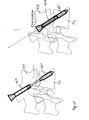
- the sleeve 10 is screwed through the upper vertebral body 51 into the lower vertebral body 52, wherein the sleeve 10 passes through the intervertebral space 53.
- the central region 12 with the spreading elements 16 comes to lie within the lower vertebral body 52. If the screw 20 is subsequently screwed in, the spreading elements 16 spread apart within the vertebral body 52 in order, for example, to erect and stabilize it.
- a stop 26 is arranged against which the free end of the rear region 13 of the sleeve 10 strikes when the screw 20 is screwed in, so that the front region 11 the sleeve 10 can be pulled against the rear portion 13 of the sleeve 10 and spread the spreading elements 16 in the central region 12.
- the screw 20 is designed to be cannulated, so that a guide wire 30 can first be introduced during implantation, via which the sleeve 10 and finally the screw 20 can subsequently be inserted.
- FIGS. 5 to 8 show a further embodiment of a sleeve 10 ', which can be used without a screw.
- the sleeve 10 ' is made of a memory metal, in particular nitinol, which changes the shape, in particular when the body temperature is reached.
- the sleeve 10 ' also has longitudinally extending slots 15 between which the spreading elements 16 are formed.
- the sleeve 10 "has slots 15" which extend longitudinally but are inclined towards the longitudinal direction twisted against each other, the spread between the slots 15 '' spreading elements 16 spread, and they remain almost against each other in particular when rotating the front portion 11 against the rear portion 13 and form a circumferential bead (see. FIG. 13 ).
- FIGS. 17 to 19 it is shown how the sleeve 10 'comes to rest in the adjacent vertebral bodies 51, 52.
- the sleeve 10 ' is inserted through the upper vertebral body 51, passes through the intervertebral space 53 and is inserted so far that the front portion 11 and the central portion 12 come to lie in the lower vertebral body 52.
- the spreading elements 16 stabilize after spreading the sleeve 10 'the lower vertebral body 52 (see. Figures 18 and 19 ).
- FIGS. 20 to 22 is a further embodiment of a sleeve 10 '''shown with a further embodiment of a screw 20'.
- the FIGS. 23 to 29 show how the sleeve 10 '''and the screw 20' in two adjacent vertebral bodies 51, 52 are introduced.
- FIGS. 20 to 22 show various views of a first embodiment of a sleeve 10 '''with a front portion 11 and an adjoining rear portion 13.
- the front portion 11 carries an external thread 14.
- an internal thread 16 is arranged with a first pitch.
- the rear portion 13 may be conical.
- the screw 20 has a front portion 21, an adjoining central portion 22 and an adjoining rear portion 23.
- a first external thread 24 is arranged, while in the rear portion 23, a second Au- ⁇ engewinde 25 is arranged.
- the first external thread 24 has a third pitch, while the second external thread 25 has a fourth pitch.
- the fourth pitch of the second external thread 25 corresponds in particular to the first pitch of the first internal thread 16 of the sleeve 10.
- the third pitch and the fourth pitch may be selected differently.
- the screw 20 ' in particular along a guide wire 30, inserted into the vertebral bodies 51, 52, wherein the screw 20' is screwed through the upper vertebral body 51 into the lower vertebral body 52, wherein the screw 20 'the disc space 53rd interspersed.
- the central region 12 comes to lie in the intervertebral space 53 (cf. Figures 23 and 24 ).
- the sleeve 10 '''on the screw 20' is rotated (see. FIGS. 24 to 27 ).
- the second external thread engages 25 of the screw 20 'in the internal thread 16 of the sleeve 10''' a.
- the sleeve 10 ''' can in particular be screwed in so far that a stop 26 of the screw 20' against the distal edge of the sleeve 10 '''is pulled and then the vertebral bodies 51, 52 are distracted (see. FIG. 24 . 25 and 26 ).
- the sleeve 10 ''' only be screwed so far that it remains in the superior vertebral body 51 and only the central portion 22 of the screw 20' interspersed the intervertebral space 53 (see. FIG. 27 ).
- the central portion 22 of the screw 20 ' is formed elastically. If the sleeve 10 '''only screwed so far that it remains in the superior vertebral body 51 and only the central portion 22 of the screw 20' intersperses the intervertebral space 53, it is possible to tilt the vertebral bodies 51, 52 against each other, to rotate and to move relative to each other, so that in this way an intervertebral disc can be simulated.
Landscapes
- Health & Medical Sciences (AREA)
- Orthopedic Medicine & Surgery (AREA)
- Life Sciences & Earth Sciences (AREA)
- Surgery (AREA)
- Neurology (AREA)
- Heart & Thoracic Surgery (AREA)
- Engineering & Computer Science (AREA)
- Biomedical Technology (AREA)
- Nuclear Medicine, Radiotherapy & Molecular Imaging (AREA)
- Medical Informatics (AREA)
- Molecular Biology (AREA)
- Animal Behavior & Ethology (AREA)
- General Health & Medical Sciences (AREA)
- Public Health (AREA)
- Veterinary Medicine (AREA)
- Prostheses (AREA)
- Surgical Instruments (AREA)
Priority Applications (2)
| Application Number | Priority Date | Filing Date | Title |
|---|---|---|---|
| ES10013960.9T ES2564415T3 (es) | 2010-10-26 | 2010-10-26 | Dispositivo para estabilizar una columna vertebral |
| EP10013960.9A EP2446842B1 (fr) | 2010-10-26 | 2010-10-26 | Dispositif de stabilisation d'une colonne vertébrale |
Applications Claiming Priority (1)
| Application Number | Priority Date | Filing Date | Title |
|---|---|---|---|
| EP10013960.9A EP2446842B1 (fr) | 2010-10-26 | 2010-10-26 | Dispositif de stabilisation d'une colonne vertébrale |
Publications (2)
| Publication Number | Publication Date |
|---|---|
| EP2446842A1 true EP2446842A1 (fr) | 2012-05-02 |
| EP2446842B1 EP2446842B1 (fr) | 2015-12-02 |
Family
ID=43721489
Family Applications (1)
| Application Number | Title | Priority Date | Filing Date |
|---|---|---|---|
| EP10013960.9A Not-in-force EP2446842B1 (fr) | 2010-10-26 | 2010-10-26 | Dispositif de stabilisation d'une colonne vertébrale |
Country Status (2)
| Country | Link |
|---|---|
| EP (1) | EP2446842B1 (fr) |
| ES (1) | ES2564415T3 (fr) |
Cited By (5)
| Publication number | Priority date | Publication date | Assignee | Title |
|---|---|---|---|---|
| EP2676621A1 (fr) * | 2012-06-18 | 2013-12-25 | Biedermann Technologies GmbH & Co. KG | Ancrage osseux |
| CN104546106A (zh) * | 2015-01-26 | 2015-04-29 | 山东省文登整骨医院 | 一种高把持力骨螺钉 |
| US10010361B2 (en) | 2012-06-18 | 2018-07-03 | Biedermann Technologies Gmbh & Co. Kg | Bone anchor |
| CN111616788A (zh) * | 2020-05-23 | 2020-09-04 | 徐州长风生物科技有限公司 | 一种具有高抗拉拔能力的骨螺钉 |
| KR20210085510A (ko) * | 2019-12-30 | 2021-07-08 | 주식회사 엔닥 | 팽창 복원 기능을 구비한 뼈 고정용 스크류 |
Citations (6)
| Publication number | Priority date | Publication date | Assignee | Title |
|---|---|---|---|---|
| US20020198527A1 (en) * | 2001-06-21 | 2002-12-26 | Helmut Muckter | Implantable screw for stabilization of a joint or a bone fracture |
| US20050143735A1 (en) * | 2003-04-29 | 2005-06-30 | Kyle Richard F. | Double compression unloadable screw system |
| US20060052788A1 (en) * | 2003-02-04 | 2006-03-09 | Thelen Sarah L | Expandable fixation devices for minimally invasive surgery |
| US20080221623A1 (en) * | 2005-10-17 | 2008-09-11 | Gooch Hubert L | Systems and Methods for the Medical Treatment of Structural Tissue |
| US20090131992A1 (en) * | 2007-11-02 | 2009-05-21 | Stout Medical Group, L.P. | Expandable attachment device and method |
| US20100168751A1 (en) * | 2002-03-19 | 2010-07-01 | Anderson D Greg | Method, Implant & Instruments for Percutaneous Expansion of the Spinal Canal |
-
2010
- 2010-10-26 EP EP10013960.9A patent/EP2446842B1/fr not_active Not-in-force
- 2010-10-26 ES ES10013960.9T patent/ES2564415T3/es active Active
Patent Citations (6)
| Publication number | Priority date | Publication date | Assignee | Title |
|---|---|---|---|---|
| US20020198527A1 (en) * | 2001-06-21 | 2002-12-26 | Helmut Muckter | Implantable screw for stabilization of a joint or a bone fracture |
| US20100168751A1 (en) * | 2002-03-19 | 2010-07-01 | Anderson D Greg | Method, Implant & Instruments for Percutaneous Expansion of the Spinal Canal |
| US20060052788A1 (en) * | 2003-02-04 | 2006-03-09 | Thelen Sarah L | Expandable fixation devices for minimally invasive surgery |
| US20050143735A1 (en) * | 2003-04-29 | 2005-06-30 | Kyle Richard F. | Double compression unloadable screw system |
| US20080221623A1 (en) * | 2005-10-17 | 2008-09-11 | Gooch Hubert L | Systems and Methods for the Medical Treatment of Structural Tissue |
| US20090131992A1 (en) * | 2007-11-02 | 2009-05-21 | Stout Medical Group, L.P. | Expandable attachment device and method |
Cited By (11)
| Publication number | Priority date | Publication date | Assignee | Title |
|---|---|---|---|---|
| EP2676621A1 (fr) * | 2012-06-18 | 2013-12-25 | Biedermann Technologies GmbH & Co. KG | Ancrage osseux |
| CN103505278A (zh) * | 2012-06-18 | 2014-01-15 | 比德尔曼技术有限责任两合公司 | 骨锚固器 |
| EP2910210A1 (fr) * | 2012-06-18 | 2015-08-26 | Biedermann Technologies GmbH & Co. KG | Ancrage osseux |
| US10010361B2 (en) | 2012-06-18 | 2018-07-03 | Biedermann Technologies Gmbh & Co. Kg | Bone anchor |
| US10092339B2 (en) | 2012-06-18 | 2018-10-09 | Biedermann Technologies Gmbh & Co. Kg | Bone anchor |
| US11116556B2 (en) | 2012-06-18 | 2021-09-14 | Biedermann Technologies Gmbh & Co. Kg | Bone anchor |
| US12042195B2 (en) | 2012-06-18 | 2024-07-23 | Biedermann Technologies Gmbh & Co. Kg | Bone anchor |
| CN104546106A (zh) * | 2015-01-26 | 2015-04-29 | 山东省文登整骨医院 | 一种高把持力骨螺钉 |
| KR20210085510A (ko) * | 2019-12-30 | 2021-07-08 | 주식회사 엔닥 | 팽창 복원 기능을 구비한 뼈 고정용 스크류 |
| CN111616788A (zh) * | 2020-05-23 | 2020-09-04 | 徐州长风生物科技有限公司 | 一种具有高抗拉拔能力的骨螺钉 |
| CN111616788B (zh) * | 2020-05-23 | 2022-04-26 | 北京庆北医疗器械有限公司 | 一种具有高抗拉拔能力的骨螺钉及打孔装置 |
Also Published As
| Publication number | Publication date |
|---|---|
| ES2564415T3 (es) | 2016-03-22 |
| EP2446842B1 (fr) | 2015-12-02 |
Similar Documents
| Publication | Publication Date | Title |
|---|---|---|
| EP3117787B1 (fr) | Vis pediculaire avec tulipe | |
| EP1570795B1 (fr) | Dispositif pour stabilisation dynamique du rachis ou des os et élément en forme de tige pour ce dispositif | |
| DE69630817T2 (de) | Wirbelsäulenhalterunsvorrichtung | |
| EP1339335B1 (fr) | Dispositif pour fixer des os, notamment des corps vertebraux les uns par rapport aux autres | |
| EP3954312B1 (fr) | Instrument chirurgical | |
| EP2692304B1 (fr) | Instrumentation chirurgicale | |
| DE602004011613T2 (de) | Wirbel-osteosynthese-gerät | |
| EP1753355B1 (fr) | Vis à os avec articulation | |
| EP1684652B1 (fr) | Element d'ancrage osseux et dispositif de stabilisation comprenant un tel element d'ancrage osseux | |
| EP2446842B1 (fr) | Dispositif de stabilisation d'une colonne vertébrale | |
| EP1720470A1 (fr) | Barre de jonction pour element de jonction osseuse | |
| DE102008017741A1 (de) | Vorrichtung zur Stabilisierung von Röhrenknochenbrüchen | |
| EP2911601B1 (fr) | Vis à os | |
| DE102013001933B4 (de) | Knochenschraube zur Fixation eines Knochenschrauben-Stabsystems | |
| EP2893891A1 (fr) | Dispositif de fermeture pour vis canulée pour fracture osseuse | |
| EP4223241A1 (fr) | Dilatateur pour chirurgie de la colonne vertébrale | |
| WO2019192932A1 (fr) | Implant isg pour la fusion minimalement invasive de l'articulation sacro-iliaque | |
| EP2422752A1 (fr) | Système d'implant pour la fusion de vertèbres | |
| EP2768401B1 (fr) | Kit d'implantation mtv | |
| DE102014107495A1 (de) | Knochenschraubensystem | |
| EP4178474B1 (fr) | Dispositif d'ostéosynthèse ayant l'apparence d'une lame | |
| DE202020105885U1 (de) | Klingenartige Osteosynthesevorrichtung |
Legal Events
| Date | Code | Title | Description |
|---|---|---|---|
| PUAI | Public reference made under article 153(3) epc to a published international application that has entered the european phase |
Free format text: ORIGINAL CODE: 0009012 |
|
| AK | Designated contracting states |
Kind code of ref document: A1 Designated state(s): AL AT BE BG CH CY CZ DE DK EE ES FI FR GB GR HR HU IE IS IT LI LT LU LV MC MK MT NL NO PL PT RO RS SE SI SK SM TR |
|
| AX | Request for extension of the european patent |
Extension state: BA ME |
|
| 17P | Request for examination filed |
Effective date: 20121031 |
|
| 17Q | First examination report despatched |
Effective date: 20130225 |
|
| GRAP | Despatch of communication of intention to grant a patent |
Free format text: ORIGINAL CODE: EPIDOSNIGR1 |
|
| RIC1 | Information provided on ipc code assigned before grant |
Ipc: A61B 17/70 20060101AFI20150506BHEP Ipc: A61B 17/72 20060101ALI20150506BHEP Ipc: A61B 17/00 20060101ALI20150506BHEP Ipc: A61B 17/86 20060101ALI20150506BHEP Ipc: A61B 17/68 20060101ALI20150506BHEP |
|
| INTG | Intention to grant announced |
Effective date: 20150529 |
|
| GRAS | Grant fee paid |
Free format text: ORIGINAL CODE: EPIDOSNIGR3 |
|
| GRAA | (expected) grant |
Free format text: ORIGINAL CODE: 0009210 |
|
| AK | Designated contracting states |
Kind code of ref document: B1 Designated state(s): AL AT BE BG CH CY CZ DE DK EE ES FI FR GB GR HR HU IE IS IT LI LT LU LV MC MK MT NL NO PL PT RO RS SE SI SK SM TR |
|
| REG | Reference to a national code |
Ref country code: GB Ref legal event code: FG4D Free format text: NOT ENGLISH |
|
| REG | Reference to a national code |
Ref country code: AT Ref legal event code: REF Ref document number: 763229 Country of ref document: AT Kind code of ref document: T Effective date: 20151215 Ref country code: CH Ref legal event code: EP |
|
| REG | Reference to a national code |
Ref country code: IE Ref legal event code: FG4D Free format text: LANGUAGE OF EP DOCUMENT: GERMAN |
|
| REG | Reference to a national code |
Ref country code: DE Ref legal event code: R096 Ref document number: 502010010723 Country of ref document: DE |
|
| REG | Reference to a national code |
Ref country code: CH Ref legal event code: NV Representative=s name: R.A. EGLI AND CO, PATENTANWAELTE, CH |
|
| REG | Reference to a national code |
Ref country code: SE Ref legal event code: TRGR Ref country code: ES Ref legal event code: FG2A Ref document number: 2564415 Country of ref document: ES Kind code of ref document: T3 Effective date: 20160322 |
|
| REG | Reference to a national code |
Ref country code: NL Ref legal event code: FP |
|
| REG | Reference to a national code |
Ref country code: LT Ref legal event code: MG4D |
|
| PG25 | Lapsed in a contracting state [announced via postgrant information from national office to epo] |
Ref country code: NO Free format text: LAPSE BECAUSE OF FAILURE TO SUBMIT A TRANSLATION OF THE DESCRIPTION OR TO PAY THE FEE WITHIN THE PRESCRIBED TIME-LIMIT Effective date: 20160302 Ref country code: HR Free format text: LAPSE BECAUSE OF FAILURE TO SUBMIT A TRANSLATION OF THE DESCRIPTION OR TO PAY THE FEE WITHIN THE PRESCRIBED TIME-LIMIT Effective date: 20151202 Ref country code: LT Free format text: LAPSE BECAUSE OF FAILURE TO SUBMIT A TRANSLATION OF THE DESCRIPTION OR TO PAY THE FEE WITHIN THE PRESCRIBED TIME-LIMIT Effective date: 20151202 |
|
| PG25 | Lapsed in a contracting state [announced via postgrant information from national office to epo] |
Ref country code: FI Free format text: LAPSE BECAUSE OF FAILURE TO SUBMIT A TRANSLATION OF THE DESCRIPTION OR TO PAY THE FEE WITHIN THE PRESCRIBED TIME-LIMIT Effective date: 20151202 Ref country code: PL Free format text: LAPSE BECAUSE OF FAILURE TO SUBMIT A TRANSLATION OF THE DESCRIPTION OR TO PAY THE FEE WITHIN THE PRESCRIBED TIME-LIMIT Effective date: 20151202 Ref country code: RS Free format text: LAPSE BECAUSE OF FAILURE TO SUBMIT A TRANSLATION OF THE DESCRIPTION OR TO PAY THE FEE WITHIN THE PRESCRIBED TIME-LIMIT Effective date: 20151202 Ref country code: GR Free format text: LAPSE BECAUSE OF FAILURE TO SUBMIT A TRANSLATION OF THE DESCRIPTION OR TO PAY THE FEE WITHIN THE PRESCRIBED TIME-LIMIT Effective date: 20160303 Ref country code: LV Free format text: LAPSE BECAUSE OF FAILURE TO SUBMIT A TRANSLATION OF THE DESCRIPTION OR TO PAY THE FEE WITHIN THE PRESCRIBED TIME-LIMIT Effective date: 20151202 |
|
| PG25 | Lapsed in a contracting state [announced via postgrant information from national office to epo] |
Ref country code: IS Free format text: LAPSE BECAUSE OF FAILURE TO SUBMIT A TRANSLATION OF THE DESCRIPTION OR TO PAY THE FEE WITHIN THE PRESCRIBED TIME-LIMIT Effective date: 20151202 |
|
| PG25 | Lapsed in a contracting state [announced via postgrant information from national office to epo] |
Ref country code: CZ Free format text: LAPSE BECAUSE OF FAILURE TO SUBMIT A TRANSLATION OF THE DESCRIPTION OR TO PAY THE FEE WITHIN THE PRESCRIBED TIME-LIMIT Effective date: 20151202 |
|
| PG25 | Lapsed in a contracting state [announced via postgrant information from national office to epo] |
Ref country code: EE Free format text: LAPSE BECAUSE OF FAILURE TO SUBMIT A TRANSLATION OF THE DESCRIPTION OR TO PAY THE FEE WITHIN THE PRESCRIBED TIME-LIMIT Effective date: 20151202 Ref country code: IS Free format text: LAPSE BECAUSE OF FAILURE TO SUBMIT A TRANSLATION OF THE DESCRIPTION OR TO PAY THE FEE WITHIN THE PRESCRIBED TIME-LIMIT Effective date: 20160402 Ref country code: SK Free format text: LAPSE BECAUSE OF FAILURE TO SUBMIT A TRANSLATION OF THE DESCRIPTION OR TO PAY THE FEE WITHIN THE PRESCRIBED TIME-LIMIT Effective date: 20151202 Ref country code: SM Free format text: LAPSE BECAUSE OF FAILURE TO SUBMIT A TRANSLATION OF THE DESCRIPTION OR TO PAY THE FEE WITHIN THE PRESCRIBED TIME-LIMIT Effective date: 20151202 Ref country code: RO Free format text: LAPSE BECAUSE OF FAILURE TO SUBMIT A TRANSLATION OF THE DESCRIPTION OR TO PAY THE FEE WITHIN THE PRESCRIBED TIME-LIMIT Effective date: 20151202 Ref country code: PT Free format text: LAPSE BECAUSE OF FAILURE TO SUBMIT A TRANSLATION OF THE DESCRIPTION OR TO PAY THE FEE WITHIN THE PRESCRIBED TIME-LIMIT Effective date: 20160404 |
|
| REG | Reference to a national code |
Ref country code: DE Ref legal event code: R097 Ref document number: 502010010723 Country of ref document: DE |
|
| PLBE | No opposition filed within time limit |
Free format text: ORIGINAL CODE: 0009261 |
|
| STAA | Information on the status of an ep patent application or granted ep patent |
Free format text: STATUS: NO OPPOSITION FILED WITHIN TIME LIMIT |
|
| PG25 | Lapsed in a contracting state [announced via postgrant information from national office to epo] |
Ref country code: DK Free format text: LAPSE BECAUSE OF FAILURE TO SUBMIT A TRANSLATION OF THE DESCRIPTION OR TO PAY THE FEE WITHIN THE PRESCRIBED TIME-LIMIT Effective date: 20151202 |
|
| 26N | No opposition filed |
Effective date: 20160905 |
|
| PG25 | Lapsed in a contracting state [announced via postgrant information from national office to epo] |
Ref country code: SI Free format text: LAPSE BECAUSE OF FAILURE TO SUBMIT A TRANSLATION OF THE DESCRIPTION OR TO PAY THE FEE WITHIN THE PRESCRIBED TIME-LIMIT Effective date: 20151202 |
|
| PG25 | Lapsed in a contracting state [announced via postgrant information from national office to epo] |
Ref country code: BE Free format text: LAPSE BECAUSE OF NON-PAYMENT OF DUE FEES Effective date: 20161031 |
|
| PG25 | Lapsed in a contracting state [announced via postgrant information from national office to epo] |
Ref country code: MC Free format text: LAPSE BECAUSE OF FAILURE TO SUBMIT A TRANSLATION OF THE DESCRIPTION OR TO PAY THE FEE WITHIN THE PRESCRIBED TIME-LIMIT Effective date: 20151202 |
|
| REG | Reference to a national code |
Ref country code: FR Ref legal event code: ST Effective date: 20170630 |
|
| PG25 | Lapsed in a contracting state [announced via postgrant information from national office to epo] |
Ref country code: FR Free format text: LAPSE BECAUSE OF NON-PAYMENT OF DUE FEES Effective date: 20161102 |
|
| PG25 | Lapsed in a contracting state [announced via postgrant information from national office to epo] |
Ref country code: LU Free format text: LAPSE BECAUSE OF NON-PAYMENT OF DUE FEES Effective date: 20161026 |
|
| REG | Reference to a national code |
Ref country code: BE Ref legal event code: MM Effective date: 20161031 |
|
| REG | Reference to a national code |
Ref country code: DE Ref legal event code: R082 Ref document number: 502010010723 Country of ref document: DE Representative=s name: BLUMBACH ZINNGREBE PATENTANWAELTE PARTG MBB, DE Ref country code: DE Ref legal event code: R082 Ref document number: 502010010723 Country of ref document: DE Representative=s name: BLUMBACH ZINNGREBE PATENT- UND RECHTSANWAELTE , DE |
|
| PG25 | Lapsed in a contracting state [announced via postgrant information from national office to epo] |
Ref country code: HU Free format text: LAPSE BECAUSE OF FAILURE TO SUBMIT A TRANSLATION OF THE DESCRIPTION OR TO PAY THE FEE WITHIN THE PRESCRIBED TIME-LIMIT; INVALID AB INITIO Effective date: 20101026 Ref country code: CY Free format text: LAPSE BECAUSE OF FAILURE TO SUBMIT A TRANSLATION OF THE DESCRIPTION OR TO PAY THE FEE WITHIN THE PRESCRIBED TIME-LIMIT Effective date: 20151202 |
|
| PG25 | Lapsed in a contracting state [announced via postgrant information from national office to epo] |
Ref country code: TR Free format text: LAPSE BECAUSE OF FAILURE TO SUBMIT A TRANSLATION OF THE DESCRIPTION OR TO PAY THE FEE WITHIN THE PRESCRIBED TIME-LIMIT Effective date: 20151202 Ref country code: MT Free format text: LAPSE BECAUSE OF FAILURE TO SUBMIT A TRANSLATION OF THE DESCRIPTION OR TO PAY THE FEE WITHIN THE PRESCRIBED TIME-LIMIT Effective date: 20151202 Ref country code: MK Free format text: LAPSE BECAUSE OF FAILURE TO SUBMIT A TRANSLATION OF THE DESCRIPTION OR TO PAY THE FEE WITHIN THE PRESCRIBED TIME-LIMIT Effective date: 20151202 |
|
| PG25 | Lapsed in a contracting state [announced via postgrant information from national office to epo] |
Ref country code: BG Free format text: LAPSE BECAUSE OF FAILURE TO SUBMIT A TRANSLATION OF THE DESCRIPTION OR TO PAY THE FEE WITHIN THE PRESCRIBED TIME-LIMIT Effective date: 20151202 |
|
| PG25 | Lapsed in a contracting state [announced via postgrant information from national office to epo] |
Ref country code: AL Free format text: LAPSE BECAUSE OF FAILURE TO SUBMIT A TRANSLATION OF THE DESCRIPTION OR TO PAY THE FEE WITHIN THE PRESCRIBED TIME-LIMIT Effective date: 20151202 |
|
| PGFP | Annual fee paid to national office [announced via postgrant information from national office to epo] |
Ref country code: IE Payment date: 20191021 Year of fee payment: 10 Ref country code: NL Payment date: 20191022 Year of fee payment: 10 Ref country code: SE Payment date: 20191023 Year of fee payment: 10 |
|
| PGFP | Annual fee paid to national office [announced via postgrant information from national office to epo] |
Ref country code: ES Payment date: 20191120 Year of fee payment: 10 Ref country code: IT Payment date: 20191021 Year of fee payment: 10 |
|
| PGFP | Annual fee paid to national office [announced via postgrant information from national office to epo] |
Ref country code: AT Payment date: 20191018 Year of fee payment: 10 |
|
| PGFP | Annual fee paid to national office [announced via postgrant information from national office to epo] |
Ref country code: GB Payment date: 20191023 Year of fee payment: 10 |
|
| REG | Reference to a national code |
Ref country code: SE Ref legal event code: EUG |
|
| REG | Reference to a national code |
Ref country code: NL Ref legal event code: MM Effective date: 20201101 |
|
| REG | Reference to a national code |
Ref country code: AT Ref legal event code: MM01 Ref document number: 763229 Country of ref document: AT Kind code of ref document: T Effective date: 20201026 |
|
| GBPC | Gb: european patent ceased through non-payment of renewal fee |
Effective date: 20201026 |
|
| PG25 | Lapsed in a contracting state [announced via postgrant information from national office to epo] |
Ref country code: NL Free format text: LAPSE BECAUSE OF NON-PAYMENT OF DUE FEES Effective date: 20201101 |
|
| PG25 | Lapsed in a contracting state [announced via postgrant information from national office to epo] |
Ref country code: AT Free format text: LAPSE BECAUSE OF NON-PAYMENT OF DUE FEES Effective date: 20201026 Ref country code: GB Free format text: LAPSE BECAUSE OF NON-PAYMENT OF DUE FEES Effective date: 20201026 Ref country code: SE Free format text: LAPSE BECAUSE OF NON-PAYMENT OF DUE FEES Effective date: 20201027 |
|
| PG25 | Lapsed in a contracting state [announced via postgrant information from national office to epo] |
Ref country code: IT Free format text: LAPSE BECAUSE OF NON-PAYMENT OF DUE FEES Effective date: 20201026 Ref country code: IE Free format text: LAPSE BECAUSE OF NON-PAYMENT OF DUE FEES Effective date: 20201026 |
|
| REG | Reference to a national code |
Ref country code: ES Ref legal event code: FD2A Effective date: 20220128 |
|
| PGFP | Annual fee paid to national office [announced via postgrant information from national office to epo] |
Ref country code: DE Payment date: 20211020 Year of fee payment: 12 |
|
| PGFP | Annual fee paid to national office [announced via postgrant information from national office to epo] |
Ref country code: CH Payment date: 20211022 Year of fee payment: 12 |
|
| PG25 | Lapsed in a contracting state [announced via postgrant information from national office to epo] |
Ref country code: ES Free format text: LAPSE BECAUSE OF NON-PAYMENT OF DUE FEES Effective date: 20201027 |
|
| REG | Reference to a national code |
Ref country code: DE Ref legal event code: R119 Ref document number: 502010010723 Country of ref document: DE |
|
| REG | Reference to a national code |
Ref country code: CH Ref legal event code: PL |
|
| PG25 | Lapsed in a contracting state [announced via postgrant information from national office to epo] |
Ref country code: LI Free format text: LAPSE BECAUSE OF NON-PAYMENT OF DUE FEES Effective date: 20221031 Ref country code: DE Free format text: LAPSE BECAUSE OF NON-PAYMENT OF DUE FEES Effective date: 20230503 Ref country code: CH Free format text: LAPSE BECAUSE OF NON-PAYMENT OF DUE FEES Effective date: 20221031 |