EP2447046A2 - Procédé de formage tridimensionnel et appareil de formage tridimensionnel - Google Patents
Procédé de formage tridimensionnel et appareil de formage tridimensionnel Download PDFInfo
- Publication number
- EP2447046A2 EP2447046A2 EP11186869A EP11186869A EP2447046A2 EP 2447046 A2 EP2447046 A2 EP 2447046A2 EP 11186869 A EP11186869 A EP 11186869A EP 11186869 A EP11186869 A EP 11186869A EP 2447046 A2 EP2447046 A2 EP 2447046A2
- Authority
- EP
- European Patent Office
- Prior art keywords
- supporting
- shaping
- model
- supporting material
- supporting shell
- Prior art date
- Legal status (The legal status is an assumption and is not a legal conclusion. Google has not performed a legal analysis and makes no representation as to the accuracy of the status listed.)
- Granted
Links
Images




Classifications
-
- B—PERFORMING OPERATIONS; TRANSPORTING
- B29—WORKING OF PLASTICS; WORKING OF SUBSTANCES IN A PLASTIC STATE IN GENERAL
- B29C—SHAPING OR JOINING OF PLASTICS; SHAPING OF MATERIAL IN A PLASTIC STATE, NOT OTHERWISE PROVIDED FOR; AFTER-TREATMENT OF THE SHAPED PRODUCTS, e.g. REPAIRING
- B29C64/00—Additive manufacturing, i.e. manufacturing of three-dimensional [3D] objects by additive deposition, additive agglomeration or additive layering, e.g. by 3D printing, stereolithography or selective laser sintering
- B29C64/40—Structures for supporting 3D objects during manufacture and intended to be sacrificed after completion thereof
-
- B—PERFORMING OPERATIONS; TRANSPORTING
- B29—WORKING OF PLASTICS; WORKING OF SUBSTANCES IN A PLASTIC STATE IN GENERAL
- B29C—SHAPING OR JOINING OF PLASTICS; SHAPING OF MATERIAL IN A PLASTIC STATE, NOT OTHERWISE PROVIDED FOR; AFTER-TREATMENT OF THE SHAPED PRODUCTS, e.g. REPAIRING
- B29C64/00—Additive manufacturing, i.e. manufacturing of three-dimensional [3D] objects by additive deposition, additive agglomeration or additive layering, e.g. by 3D printing, stereolithography or selective laser sintering
- B29C64/10—Processes of additive manufacturing
- B29C64/106—Processes of additive manufacturing using only liquids or viscous materials, e.g. depositing a continuous bead of viscous material
- B29C64/112—Processes of additive manufacturing using only liquids or viscous materials, e.g. depositing a continuous bead of viscous material using individual droplets, e.g. from jetting heads
-
- B—PERFORMING OPERATIONS; TRANSPORTING
- B33—ADDITIVE MANUFACTURING TECHNOLOGY
- B33Y—ADDITIVE MANUFACTURING, i.e. MANUFACTURING OF THREE-DIMENSIONAL [3D] OBJECTS BY ADDITIVE DEPOSITION, ADDITIVE AGGLOMERATION OR ADDITIVE LAYERING, e.g. BY 3D PRINTING, STEREOLITHOGRAPHY OR SELECTIVE LASER SINTERING
- B33Y10/00—Processes of additive manufacturing
Definitions
- the present invention relates to a three-dimensional shaping apparatus and a three-dimensional shaping method for fabricating a stereoscopic shaped object in an ink-jet manner.
- an ink-jet method there are known an ink-jet method, a powder method, an optical shaping method, a sheet lamination method, an extrusion method, and the like.
- a liquefied material is injected, and then cured to form a layer through irradiation of ultraviolet light (UV), cooling or the like.
- UV ultraviolet light
- a three-dimensional shaping apparatus of a resin layer-lamination type is adapted to eject a model material and a supporting material onto a shaping plate while performing scanning in XY directions, thereby laminating layers in a height direction for attaining shaping, wherein the model material is to form a final shaped object, and the supporting material is to support protruding (overhang) portions of the model material and is also to be finally removed therefrom.
- the model material and the supporting material are formed from resins having properties of being cured by irradiation of ultraviolet light.
- An ultraviolet-light lamp capable of emitting ultraviolet light is scanned in the XY directions together with the nozzles for ejecting the model material and the supporting material, so that the model material and the supporting material ejected from the nozzles are irradiated with the ultraviolet light to be cured.
- Patent Document 1 Japanese Unexamined Patent Publication No. 2003-535712
- the supporting material is preferably made of a material having a certain degree of softness and flexibility, in consideration of ease of the removal thereof.
- a resin with softness has the problem that it tends to deform and deliquesce due to heat and humidity.
- the supporting material has a poor strength, the supporting material will collapse by being grasped by a user.
- the supporting material contains a non-curable ingredient in consideration of ease of melting thereof, the supporting material becomes sticky at its surface, which induces the problem that the user grasping the supporting material has an uncomfortable feeling.
- the supporting material is required to exhibit enough rigidity so as not to deform due to heat and humidity and also so as not to collapse even if it is grasped by a user.
- the supporting material is required to exhibit enough rigidity to support the model material.
- the present invention has been made in view of the above conventional problems and mainly aims at providing a three-dimensional shaping apparatus and a three-dimensional shaping method which are capable of facilitating removal of supporting materials while maintaining ease of handling thereof.
- a three-dimensianal shaping apparatus is a three-dimensional shaping apparatus for repeatedly performing operations for ejecting, onto a shaping plate 40, a model material MA and a supporting material SA as shaping materials while performing scanning at least in a single direction, and for curing the materials to form slices having a predetermined thickness in a height direction, and laminating these slices in the height direction for performing shaping, the model material MA being to form a final shaped object, and the supporting material SA being to support a protruding portion of the model material MA and to be finally removed, the three-dimensional shaping apparatus including: the shaping plate 40 for placing a shaped object thereon; a shaping-material ejection device including a plurality of model-material ejection nozzles 21 for ejecting the model material MA and a plurality of supporting-material ejection nozzles 22 for ejecting the supporting material SA, such that these plurality of nozzles are arranged in a single direction; a cu
- the supporting shell having higher rigidity than that of the supporting material, it is possible to attain the inconsistent properties of being easily removed after shaping and being rigid during shaping, which are required for the supporting material. That is, it is possible to prevent outflows of the supporting material with the supporting shell during the shaping, and also, it is possible to cause outflows of the supporting material coated with the supporting shell after the shaping, which enables the supporting material to be easily removed from the model material.
- the supporting material SA may be made of a water-soluble material. Accordingly, the supporting material can be dissolved and removed extremely easily, by immersing the shaped object into water in a water bath or the like, after the shaping.
- the supporting shell SS may be made of an identical material as that of the model material MA, Accordingly, the supporting shell may be formed concurrently with the shaping of the model material, which eliminates the necessity of additionally preparing a different shaping material, and whereby the number of processes can be reduced. Further, by using the common shaping material, the fabrication cost can also be reduced.
- control device may be adapted to control the shaping-material ejection device such that the model material MA is ejected and cured at positions at which the supporting shell SS is to be formed on the outer surface of the supporting material SA, and the outer surface of the supporting material SA is covered with the model material MA having a small thickness, during the formation of the respective slices. Accordingly, the model material having a small thickness can be formed on the surface of the supporting material, thereby offering the advantage of ease of formation of the supporting shell.
- the supporting shell SS may be partially provided with an exposed portion at which the supporting material SA is exposed. Accordingly, the supporting shell can be easily stripped off from the shaped object, by breaking the supporting shell at the exposed portion after the shaping for the shaped object, by immersing the shaped object into water for causing the supporting material to dissolve through the exposed portion, or the like.
- the exposed portion may include a plurality of holes 53 formed in a surface of the supporting shell SS. Accordingly, the supporting material can be dissolved through the holes by immersing the shaped object into water after the shaping.
- the exposed portion may include a cutout line shape 51 formed from a partial opening provided straightly in a surface of the supporting shell SS. Accordingly, the supporting shell can be easily broken along the cutout line with a hand.
- the supporting shell SS may include small pieces 54 having a certain size which are arranged so as to be spaced apart from one another, whereby exposed portions are formed between the small pieces 54. Accordingly, if the shaped object is immersed into water after the shaping, the supporting material is dissolved through the exposed portions, and the supporting shell is finely disassembled into small pieces, whereby a larger part of the supporting material will be exposed. This offers the advantage that the supporting material can be removed more easily and within a shorter time.
- the supporting shell SS may be partially provided with a slot portion having a reduced thickness. This makes it easier to break the supporting shell at the slot portion having the reduced thickness after the shaping for the shaped object. Particularly, since the supporting material is prevented from being directly exposed to the outside, it is possible to prevent the supporting material from contacting with air, thereby offering the advantages of preventing deliquescence thereof and preventing outflows of the supporting material through an exposed portion.
- the supporting shell SS may be formed so as to be spaced apart from a shaped object formed from the shaped model material MA for preventing contact therebetween. Accordingly, portions at which the model material and the supporting shell are shaped continuously can be eliminated, which prevents partial breakages of the model material in the shaped object, when the supporting shell is stripped off from the supporting material. This enables the model material to be smoothly removed, and the shaped object having higher quality can be provided.
- the supporting shell SS may be formed to have a shape resulted from simplifying an outer shape of the shaped object, and the supporting material SA may be charged between the supporting shell SS and the model material MA. Accordingly, when the shaped object has a complicated outer shape, the supporting shell can be formed such that it is not along the complicated outer shape, which offers the advantage of facilitation of the removal of the supporting shell therefrom.
- the slices may be such that the positions at which the supporting shell SS is formed are located at peripheries outside the model material MA forming the shaped object. Accordingly, the shaped object can be formed such that it has intermittent portions in the horizontal direction at which the supporting shell is not formed on the supporting material, and thus, the supporting material is exposed. This can prevent the supporting shell from being bonded to the shaped object, thereby facilitating the removal of the supporting shell and protecting the shaped object.
- the slices may include a slice which is not provided with the supporting shell on the surface of the supporting material SA. This enables forming the shaped object such that it has intermittent portions in the height direction at which the supporting shell is not formed on the supporting material, and thus, the supporting material is exposed. This can prevent the supporting shell from being bonded to the shaped object, thereby facilitating the removal of the supporting shell and protecting the shaped object.
- the supporting shell SS cannot be provided on the outer surface of the supporting material SA at a portion where its angle abruptly changes. Accordingly, the supporting shell is not formed at edge portions, which facilitates breaking of the supporting shell with hands.
- a three-dimensional shaping method is a three-dimensional shaping method for repeatedly performing operations for ejecting, onto a shaping plate 40, a model material MA and a supporting material SA as shaping materials while performing scanning at least in a single direction, and for curing the materials to form slices with a predetermined thickness in a height direction, and laminating the slices in the height direction for performing shaping, the model material MA being to form a final shaped object, and the supporting material SA being to support a protruding portion of the model material MA and to be finally removed, the three-dimensional shaping method including the steps of: reciprocatingly scanning, in a single direction, a head portion 20 including a shaping-material ejection device for ejecting the model material MA and/or the supporting material SA onto the shaping plate 40 and further including the curing device 24 for curing the model material MA and the supporting material SA, while causing the shaping-material ejection device to eject the model material MA and the supporting material SA onto the shaping plate 40 at least in one of forward and rear
- the supporting shell having higher rigidity than that of the supporting material, it is possible to attain the inconsistent properties of being easily removed after shaping and being rigid during shaping, which are required for the supporting material. That is, it is possible to prevent outflows of the supporting material with the supporting shell during the shaping, and also, it is possible to cause outflows of the supporting material coated with the supporting shell after the shaping, whereby the supporting material can be easily removed from the model material.
- the sizes of members, the positional relationships thereamong and the like are exaggeratedly illustrated in the drawings, in some cases, for clarification of the description.
- like names and like reference characters are used to denote the same members or members with the same qualities, and detailed descriptions thereof will be properly omitted.
- the respective components constituting the present invention may be realized, such that a single member constitutes a plurality of components so that the single member can function as the plurality of components, or such that a plurality of members share the functions of a single member.
- the three-dimensional shaping apparatus employed in embodiments of the present invention is electrically, magnetically or optically connected to a computer, a printer, an external storage device and other peripheral apparatuses for performing manipulations, control, displaying and other processes, through serial connections or parallel connections using IEEE1394, RS-232x, RS-422, RS-423, RS-485, USBs and the like or through networks using 10BASE-T, 100BASE-TX, 1000BASE-T and the like, thereby enabling communication therebetween.
- These connections therebetween are not limited to physical connections in a wired manner, but may also be wireless connections and the like using radio waves, infrared rays, optical communications and the like, such as Bluetooth (registered trademark), wireless LAN using IEEE802.1x, and the like.
- the three-dimensional shaping apparatus is used not only to mean the main body of the three-dimensional shaping apparatus, but also to mean a three-dimensional shaping system including, in combination therewith, peripheral apparatuses such as a computer, an external storage device.
- the three-dimensional shaping apparatus, the three-dimensional shaping method and three-dimensional shaping programs are not intended to be restricted to systems themselves for performing three-dimensional shaping, and apparatuses and methods which are adapted to perform, in a hardware manner, inputting, outputting, displaying, calculations, communications and other processes relating to image formation. Apparatuses and methods adapted to realize such processes in a software manner are also included in the scope of the present invention.
- an apparatus and a system enabled to perform image formation and processes relating thereto, by incorporating, into a general-purpose circuit or a computer, software, programs, plug-ins, objects, libraries, applets, compilers, modules, macros capable of operating in certain programs, and such an apparatus and system also correspond to the three-dimensional shaping apparatus, the three-dimensional shaping method, the three-dimensional shaping program and a computer-readable recording medium, according to the present invention.
- the term "computer” includes workstations, terminals, portable electronic apparatuses, cellular phones using PDC, CDMA, WCDMA, FOMA (registered trademark), GSM and IMT2000 or 4th generation cellular phones, PHSs, PDAs, pagers, smartphones and other electronic devices, as well as general-purpose or dedicated computers.
- programs are not limited to those used solely, and such programs can be used in aspects where they function as portions of certain computer programs, software, services and the like, aspects where they function by being called as required, aspects where they are provided as services in OSs or other environments, aspects where they operate by being resident in environments or aspects where they operate in backgrounds. Also, such programs can be used as other supporting programs.
- Fig. 1 illustrates a block diagram of a three-dimensional shaping system 100 according to a first embodiment of the present invention.
- the three-dimensional shaping system 100 is adapted to eject shaping materials in a liquid or fluid state in an ink-jet manner, and then, cure and laminate the materials for fabricating an arbitrary shaped object.
- a model material MA and a supporting material SA are employed, wherein the model material MA is to form a final shaped object, and the supporting material SA is shaped to support protruding portions of the model material MA and is to be finally removed therefrom.
- the three-dimensional shaping system 100 illustrated in Fig. 1 is constituted by a three-dimensional shaping apparatus 2, and a set-data creating apparatus 1 (a computer PC in Fig. 1 ) which transmits set data to the three-dimensional shaping apparatus 2.
- the three-dimensional shaping apparatus 2 includes a control device 10, a head portion 20, and a shaping plate 40.
- the head portion 20 includes, as shaping-material ejection devices, model-material ejection nozzles 21 for ejecting the model material MA and supporting-material ejection nozzles 22 for ejecting the support material SA.
- the head portion 20 is provided with a roller portion 25 for scraping off excess portions of these ejected shaping materials for smoothing the surfaces of the shaping materials, and further, is provided with a curing device 24 for curing the shaping materials.
- a curing device 24 for curing the shaping materials.
- an XY direction driving portion 31 and a Z-direction driving portion 32 as a horizontal driving device and a vertical driving device, respectively, wherein the horizontal driving device is for scanning the head portion 20 in horizontal directions, in such a way as to reciprocatingly scan it in an X direction and also to scan it in a Y direction orthogonal to the X direction, while the vertical driving device is for moving the positions of the head portion 20 and the shaping plate 40 with respect to each other in the height direction.
- the computer PC functions as the set-data creating apparatus 1.
- the set-data creating apparatus 1 converts this CAD data into STL data (Stereo Lithography Data), for example, further creates cross-section data provided by slicing the STL data into a plurality of thin cross-sectional parts, and then transmits the slice data to the three-dimensional shaping apparatus 2 collectively or on a slice-layer by slice-layer basis.
- STL data Stepo Lithography Data
- the control device 10 takes the cross-section data from the computer PC and controls the head portion 20, the XY-direction driving portion 31, and the Z-direction driving portion 32 according to this data.
- the XY-direction driving portion 31 is operated, and also, the model-material ejection nozzles 21 and the supporting-material ejection nozzles 22 in the head portion 20 are caused to eject, as droplets, the model material MA and the supporting material SA as shaping materials, to proper positions on the shaping plate 40, so that a cross-sectional shape is formed based on the cross-section data provided by the computer PC.
- the model material MA which is one of the shaping materials ejected on the shaping plate 40, is at least cured, so that the model material MA is changed from the liquid or fluid state to a solid, and thus, is cured.
- slice refers to a unit for laminating layers in the z direction of the shaped object, and the number of slices is equal to the value of the height divided by the thickness of a single laminated layer.
- a minimum settable thickness is determined, according to the minimum unit amounts of materials which can be ejected from the respective ejection nozzles, variations caused by eccentricity of the roller in the roller portion 25 in the upward and downward directions, and the like.
- a value determined based on the aforementioned view points is defined as the minimum slice value, and thereafter, a user can finally determine the amount of each slice, in view of the required shaping accuracy and the required shaping speed, for example.
- the amount of each slice can be determined in such a way as to maintain a minimum necessary shaping accuracy.
- shaping actions for one slice data includes a series of steps of ejecting the shaping materials in a liquid or fluid state from the model-material ejection nozzles 21 and the supporting-material ejection nozzles 22 in an ink-jet manner at least in forward paths or rearward paths at least during reciprocating operations of the head portion 20 in the X direction, further causing the roller portion 25 to work for smoothing the surfaces of the uncured shaped object at least in forward paths or rearward paths in a state where the shaped object resulted from the ejection onto the shaping plate 40 has not been cured, and then directing light with a specific wavelength from the curing device 24 to the smoothed surfaces of the shaped object for curing the shaped object, wherein these series of steps are performed at least once, but it goes without saying that the number of times these steps are performed are automatically changed according to the thickness indicated by the slice data and the required shaping accuracy.
- the maximum thickness which can be formed on the shaping plate through a single ejection from the model-material ejection nozzles 21 and the support- material ejection nozzles 22 at least in a forward or rearward path is determined by a unit amount of ejection which can maintain the cross-sectional shapes of ejected liquid droplets at substantially-circular shapes, after the liquid droplets have been landed thereon.
- the shaping plate 40 can be raised and lowered by the Z-direction driving portion 32.
- the control device 10 controls the Z-direction driving portion 32 in such a way as to lower the shaping plate 40 by a distance corresponding to the thickness of the single slice. Further, operations same as the above are repeatedly performed, so that new slices are laminated on the upper side (the upper surface) of the first single slice. Thus, a plurality of thin slices are successively created and laminated as described above, thereby attaining shaping for a shaped object.
- the computer PC adds an overhang-supporting-portion shape thereto as required, when the computer PC converts the shaped object into data.
- the control device 10 performs shaping of an overhang supporting portion SB based on the overhang-supporting-portion shape, at the same time as the shaping of the model material MA which is to form the final shaped object. More specifically, the supporting material SA, which is different from the model material MA, is ejected as droplets from the supporting-material ejection nozzles 22 to form the overhang supporting portion SB. After the shaping, the supporting material SA forming the overhang supporting portion SB is removed, thereby providing a targeted three-dimensional shaped object.
- the head portion 20 is moved by a head moving device 30 in horizontal directions, namely in XY directions, as illustrated in a plan view in Fig. 3 .
- the shaping plate 40 is moved in the height direction, namely in the Z direction, by the plate raising/lowering device (the Z-direction driving portion 32), as illustrated in Fig. 1 . Accordingly, the heights of the head portion 20 and the shaping plate 40 can be changed with respect to each other, thereby enabling stereoscopic shaping.
- the head portion 20 is reciprocatingly operated in the X direction by the head moving device 30, and then, the model material MA and the supporting material SA are ejected from a plurality of orifices which are provided in the ejection nozzles 21 and 22 and extended in the Y direction. Further, as illustrated in Fig.
- the respective ejection nozzles 21 and 22 are reciprocatingly operated in the X direction at predetermined positions, thereafter the respective ejection nozzles 21 and 22 are shifted by a predetermined amount in the Y direction and then are reciprocatingly scanned at these positions, and also, the model material MA and the supporting material SA are ejected to proper portions based on the slice data. These operations are repeated for creating a shaped object corresponding to all the set shaping data.
- the plate raising/lowering device for raising and lowering the shaping plate 40 is employed as the Z-direction driving portion 32
- the present invention is not limited to this example, and as in a three-dimensional shaping apparatus 2' illustrated in Fig. 2 , it is also possible to employ a Z-direction driving portion 32' for moving the head portion in the Z direction, while the plate 40 is fixed in the height direction. Further, movements in the XY directions can be also attained by moving the shaping plate while fixing the head portion. It is possible to eliminate the necessity of shifting of the head portion 20 in the Y direction as described above, by making the widths of the respective nozzles substantially equal to the width in the Y direction over which shaping can be performed on the shaping plate 40.
- the control device 10 controls the pattern of ejections of the shaping materials. That is, the control device 10 causes the shaping-material ejection device to eject the model material MA and the supporting material SA onto the shaping plate 40 at least in one of forward and rearward paths, during reciprocating scanning in the X direction, while reciprocatingly scanning the head portion 20 in a single direction, and further, causing the curing device 24 to cure the model material MA and the supporting material SA at least in one of the forward and rearward paths after the shaping-material ejecting device has ejected the shaping materials onto the shaping plate, thereby creating slices. Further, the control device 10 moves the positions of the shaping plate 40 and the head portion 20 with respect to each other in the height direction, and further, repeats laminating of slices to attain shaping.
- the smoothing of the surfaces of the shaping materials by the roller portion 25 is performed at least in one of forward and rearward paths, after the shaping-material ejection device has ejected the shaping materials onto the shaping plate, but before the curing device 24 cures the surfaces of the shaping materials.
- the control device 10 ejects any one shaping material out of the model material MA and the supporting material SA, smoothens the surface of the shaping material with the roller portion 25, and further cures it with the curing device 24.
- the control device 10 ejects the other shaping material which has not been ejected, smoothens the surface of the shaping material, and cures it.
- These series of processes are performed at least once for forming a single slice.
- the present invention includes repeating, a plurality of times, the aforementioned series of processes corresponding to slice data for a single layer, according to the shaping time period and the final model surface accuracy required by the user, for example.
- the surface of any one of the model material MA and the supporting material SA can be smoothed in an uncured state, then cured, and thereafter, the other of the model material MA and the supporting material SA is ejected.
- This enables the model material MA and the supporting material SA to be individually cured, thereby offering the advantage of effective prevention of mixture of the model material MA and the supporting material SA at the boundary therebetween.
- a model material MA and a supporting material SA are employed, wherein the model material MA is to form a final shaped object, and the supporting material SA is to support protruding portions of the model material MA and to be removed finally.
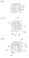
- Fig. 4 illustrates a perspective view of a shaped object formed by shaping a spherical-shaped model material MA in such a way as to cover its periphery with a rectangular-parallelepiped supporting material SA.
- Fig. 5 illustrates a cross-sectional view of the same.
- the curing device 24 is a light emitting device capable of emitting light containing at least a specific wavelength which causes the material of the model material MA to be cured in reaction thereto and, for example, the curing device 24 is an ultraviolet-ray emitting device such as an UV lamp.
- an UV light lamp it is possible to employ a halogen lamp, a mercury lamp, an LED and the like.
- the supporting material is also formed from an UV curing resin.
- thermoplastic resins as both the model material and the supporting material, by employing, as the model material, one having a melting point higher than the melting point of the supporting material, it is possible to remove the supporting material through melting, by heating the shaped object after the completion of layer laminations to a temperature higher than the melting point of the supporting material and lower than the melting point of the model material, and then maintaining the temperature thereof. Also, it is possible to employ a photo-curing resin as one of the model material and the supporting material, while employing a thermoplastic resin as the other of the model material and the supporting material.
- model material a material which can be cured by chemically reacting with a curing material.
- a liquid modifier agent into the model material as required, in order to adjust its injection characteristics, such as its viscosity and surface tension. Further, its injection characteristics can be changed, through temperature adjustments.
- Other exemplary model materials include UV photopolymers, epoxy resins, acrylic resins and urethanes.
- the supporting material SA it is possible to employ a water-swellable gel, wax, a thermoplastic resin, a water-soluble material, a meltable material and the like, as a removable material.
- a water-swellable gel such as wax, a thermoplastic resin, a water-soluble material, a meltable material and the like.
- appropriate methods for example, dynamic cleanings such as solution with water, heating, chemical reactions and hydraulic cleaning, separations utilizing thermal expansion differences through melting by irradiation of electromagnetic waves, according to properties of the supporting material.
- the supporting material Since the supporting material is finally removed, it is required to exhibit a property of being easily removed. For example, after the completion of the shaping for the shaped object, the water-soluble supporting material can be put into a water bath to be dissolved and removed. On the other hand, when the supporting material has higher solubility, the supporting material has a lower strength, and thus, when humidity is high, the supporting material is prone to deliquesce to lose its shape, drop and the like. If the supporting material has insufficient rigidity, its ability to support the model material is degraded, which may make it hard to shape the model material on the upper surface of the supporting material, thereby degrading the accuracy of the model material.
- the supporting material has increased rigidity, this increases the difficulty of dissolving the supporting material into water, thereby necessitating a longer time for removing it, when the supporting material is removed from the final shaped object. Since the supporting material is required to exhibit inconsistent properties as described above, it has been conventionally difficult to provide a supporting material capable of exhibiting optimum properties.
- a supporting shell SS as an outer shell of the supporting material SA, which can inhibit the supporting material from directly contacting with air as much as possible during shaping of the model with the shaping apparatus, thereby inhibiting the supporting material from absorbing moisture in air.
- the supporting shell SS it is possible to inhibit the supporting material inside thereof from absorbing the moisture in the air, which can improve the water-solubility performance of the supporting material.
- the supporting material SA contains a non-curable ingredient. Particularly, by enhancing the solubility thereof, it is possible to dissolve and remove the supporting material within a shorter time, by introducing it in a water bath.
- the solubility of the supporting material is not limited to water solubility and can also be solubility to a certain solvent.
- such a supporting material is in a liquid state or a gel state, and thus, becomes sticky or slimy when being touched by hands. Therefore, such a supporting material tends to be contaminated.
- the supporting shell SS is provided on the surface of the supporting material as described above, in order to protect it.
- the supporting shell SS provided on the outer surface of the supporting material SA is formed from the model material MA having higher rigidity than that of the supporting material SA. This can cause the supporting material SA to have higher rigidity at its surface, which prevents outflows of the supporting material SA.
- the supporting shell SS is formed from the model material MA ejected from the model-material ejection nozzles 21, the model-material ejection nozzles 21 in the head portion 20 can be commonly utilized as ejection nozzles for the supporting shell SS, and also, shaping of the supporting shell SS on the supporting material SA can be performed concurrently with the shaping of the model material MA. This offers advantages in terms of the cost and the speed.
- this shaping data is created, regarding the positions at which the outer surface is to be formed from the supporting material in the shaping data, in such a way as to automatically change the supporting material positioned at the outer surface to the model material or in such a way as to form a thin-film layer made of the model material to cover the outer surface of the supporting material.
- control device 10 controls the shaping-material ejection device, such that the model material MA is ejected and cured at the positions at which the supporting shell SS is to be formed on the outer surface of the supporting material SA, and the outer surface of the supporting material SA is covered with the model material MA having a small thickness, during formation of the respective slices corresponding to the created data.
- the model material MA with such a small thickness is formed on the surface of the supporting material SA, which offers the advantage of ease of formation of the supporting shell SS.
- the thickness of the thin film made of this model material it is considered that the thickness thereof is preferably about 0.1 mm to 5 mm, in view of the balance between the ease of removal and the securement of the strength.
- the supporting shell SS is made of the model material MA ejected from the model-material ejection nozzles 21, it is also possible to form a supporting shell using additionally-provided nozzles for ejecting a material different from the model material MA, provided that this material exhibits appropriate characteristics as the supporting shell.
- the material of the supporting shell is preferably a material having higher hardness than that of the model material MA and also having lower tenacity than that of the model material MA, in view of striking a higher-degree balance between the ease of removal and the securement of the strength.
- the structure which provides the supporting shell SS on the supporting material SA the higher the rigidity of the supporting shell SS, the higher the difficulty of stripping off the supporting shell SS from the shaping material. Therefore, it is preferable to additionally provide a structure for facilitating the stripping off of the supporting shell SS therefrom. More specifically, the surface of the supporting material SA is not entirely covered with the supporting shell SS, and an exposed portion which partially exposes the supporting material SA is provided. This makes it easier to break the supporting shell SS at the exposed portion after shaping of the shaped object. Further, when the supporting material SA has solubility, it is possible to dissolve the supporting material SA through the exposed portion, by immersing it in a liquid, after shaping of the shaped object.
- This enables stripping off the supporting shell SS from the shaped object without breaking it, thereby offering the advantage of labor saving in operations for removing the supporting material SA. Also, it is possible to shape the continuous outer surface on which the supporting shell SS should be formed, such that only the outer peripheral portions of this continuous outer shape have a larger thickness than those of the other portions of the outer surface on which the supporting shell SS should be formed, in order to make it easier to integrally strip off the continuous outer surface on which the supporting shell SS is formed.
- an exposed portion can be implemented in various aspects.
- an exposed portion is realized by cutout line shapes 51 formed from partial openings provided straightly in the surface of the supporting shell SS.
- This structure makes it easier to break the supporting shell SS, with a hand, along the cutout line shapes 51.
- cutout portions 52 at which the supporting shell SS is not provided, at portions where the outer surface largely changes its angle, such as edge portions of the supporting material SA. This also enables easily stripping off the supporting shell SS with hands.
- a plurality of holes 53 can be formed in the surface of the supporting shell SS.
- water is caused to intrude into the inside of the supporting shell SS over larger areas, which facilitates dissolution of the supporting material SA. It is preferable to provide such holes 53 uniformly in the surface of the supporting shell SS.
- the supporting shell SS can be divided into a plurality of small pieces 54, and these small pieces 54 can be arranged so as to be spaced from one another, thereby providing exposed portions between the small pieces 54.
- the exposed portions are formed in the surface of the supporting shell SS more uniformly, and therefore, when the shaped object is immersed into water, the supporting material SA can be effectively dissolved.
- the supporting shell SS is finely disassembled into small pieces 54, thereby exposing a larger part of the supporting material SA.
- the model material MA inside thereof can be extracted therefrom, which eliminates the necessity of breaking the supporting shell SS, thereby offering the advantage that the supporting material can be removed more easily and within a shorter time.
- the structure for forming the exposed portion or in addition thereto it is also possible to form a slot portion by partially reducing the thickness of the supporting shell. This structure makes it easier to break the supporting shell at the slot portion having such a reduced thickness. Further, since the supporting material is prevented from being directly exposed to the outside, it is possible to prevent the supporting material from contacting with external air, thereby offering the advantages of prevention of deliquescence thereof due to higher humidity and prevention of dropping of the supporting material through an exposed portion.
- such an exposed portion or slot portion can be easily formed, by partially preventing the ejection for the supporting shell SS or by limiting the amount of the ejection therefor.
- the supporting shell SS Since the supporting shell SS is finally removed, it is necessary to take caution not to break the shaped object formed by shaping the model material MA, when the supporting shell SS is stripped off therefrom. If the supporting shell is bonded to the model material, the model material may be partially broken at the time of stripping off the supporting shell therefrom. Particularly, when the supporting shell is made of the same material as that of the model material, the supporting shell may be possibly shaped, such that it is continuous to the model material. For example, in shaping the model material MA as illustrated in Fig. 10 , if an attempt is made to form a supporting shell SS on the side surfaces of the supporting material SA, the supporting shell SS is formed such that its upper ends contact with the model material MA, as illustrated in Fig. 11 .
- the model material may be partially broken at portions indicated by arrows.
- the shaping thereof is controlled, in such a way as to form the supporting shell such that the supporting shell is preliminarily spaced apart from the model material, in order to prevent contact therebetween.
- the control device 10 performs control, such that the positions at which the supporting shell SS is formed are positioned at peripheries outside the model material MA forming the shaped object.
- the supporting material SA is extended in the horizontal direction, in order to have the outermost surfaces of the supporting material SA spaced apart from the outermost surfaces of the model material MA. In this manner, it is possible to prevent the supporting shell from contacting with the model material, which prevents the possibility of breakage thereof and also facilitates stripping off of the supporting shell.
- such extensions of the supporting material SA can be also performed in the vertical direction, as well as in the horizontal direction. More specifically, in forming the model material MA as in Fig. 13 , the supporting material SA can be extended in the downward direction, in order to prevent the model material MA at the lower side from coming into contact with the supporting shell SS on the supporting material SA laminated on the upper surface of the model material MA at the lower side. As a result, the supporting shell SS is spaced, at its lower ends, apart from the model material MA at the lower side, thereby protecting the model material MA and facilitating the removal of the supporting material SA.
- the aforementioned spacing structure can be realized, by not providing the supporting shell on the lower surface of the supporting material, during shaping of slices. That is, by intermittently forming slices provided with no model material ejected on the outer edges of the supporting material, it is possible to form exposed portions in the surfaces of the supporting material, intermittently in the height direction.
- the supporting material is spaced apart from the model material by an amount corresponding to the thickness of about one to three slices, for example.
- this structure for spacing the supporting shell and the model material apart from each other is advantageous in terms of the facilitation of stripping off of the supporting shell as described above, as well as in terms of the protection of the model material. Since there is no need for breaking the supporting shell for separating it from the model material, it is possible to strip off the supporting shell with hands with smaller forces.
- the outer shape of the supporting material SA it is possible to simplify the outer shape of the supporting material SA to deform it into a spherical shape, which can simplify the shape of the supporting shell SS formed on the surface of the supporting material SA, thereby facilitating operations for removing it with hands.
- Such a deformation of the supporting material SA can be attained by simplifying the outer shape of the model material MA, for example, by repeating processes for expanding or shrinking it through image processing. It is not always necessary to make the outer shape of the supporting material coincident with that of the outer surface of the model material which will form a final shaped object as described above, and the outer shape of the supporting material can be standardized into a certain simple shape, which makes it easier to strip off the supporting shell therefrom.
- Fig. 15 illustrates an example of the head portion 20 in the ink-jet type three-dimensional shaping apparatus.
- the head portion 20 illustrated in the figure is provided with dedicated ejection nozzles for individually ejecting a model material MA and a supporting material SA, as shaping-material ejection devices.
- the head portion 20 includes model-material ejection nozzles 21 for ejecting the model material MA and supporting-material ejection nozzles 22 for ejecting the supporting material SA, such that they are spaced apart from each other in parallel with each other.
- the ejection nozzles are both provided with two nozzle rows 23, and these nozzle rows 23 are placed so as to be deviated from each other by an amount corresponding to half a nozzle as illustrated in a plan view in Fig.
- the respective nozzle rows 23 placed in the offset state are placed so as to be coincident with the same lines, so that the resolutions for the model material and the supporting material are made coincident with each other.
- the head portion 20 there are integrally provided the supporting-material ejection nozzles 22, the model-material ejection nozzles 21, the roller portion 25 and the curing device 24 in this order from the left side.
- Each of the ejection nozzles is adapted to eject an ink-type shaping material, in the way of a piezoelectric-device type ink-jet printing head. Further, the shaping material is adjusted to have such a viscosity that it can be ejected from the ejection nozzles.
- the head portion 20 is adapted to eject the model material MA at first, and thereafter, eject the supporting material SA. Further, the head portion 20 is adapted to eject the shaping materials in forward paths (in the left-to-right direction in the figure) and is adapted to cure the shaping materials with the curing device 24 in rearward paths (in the right-to-left direction in the figure).
- the head portion 20 is further provided with the roller portion 25 for smoothing the surfaces of the shaping materials by pressing the surfaces of the ejected model material MA and the ejected supporting material SA in uncured states and by removing excess portions of the shaping materials.
- the states of operations of this roller portion 25 will be described, with reference to a schematic view of Fig. 17 . In this example, there is illustrated a state where a roller main body 26 is smoothing the surface of an ejected model material MA in an uncured state.
- the roller portion 25 includes the roller main body 26 as a rotational member, a blade 27 placed to protrude toward the surface of the roller main body 26, a bath 28 for storing the shaping material scraped off by the blade 27, and a suction pipe 29 for discharging the shaping material stored in the bath 28.
- the roller main body 26 is rotated in the direction opposite from the direction of traveling of the head portion 20 (in the clockwise direction in Fig. 17 ), thereby scraping away the uncured shaping material.
- the shaping material having been scraped away adheres to the roller main body 26 and is transferred to the blade 27, and thereafter, is scraped off by the blade 27 and guided into the bath 28. Therefore, the blade 27 is fixed at an attitude inclined downwardly toward the bath 28.
- the suction pipe 29 is connected to a pump and is adapted to suction the shaping material stored in the bath 28 and then discharge it.
- the roller main body 26 is made to have an outer shape with a diameter ⁇ of about 20 mm and is adapted to have a rotational speed of about 10 rps.
- the roller portion 25 is adapted to perform scraping when the head portion 20 travels in the right-to-left direction in the figure.
- the roller portion 25 does not come into contact with the shaping materials, and similarly, the curing device 24 does not perform irradiation from the light source.
- the roller portion 25 After at least the respective nozzles 21 and 22 are caused to eject the shaping materials, for example, in a forward path in the direction of left-to-right main scanning of the head portion 20 in the figure, the roller portion 25 performs the aforementioned scraping operation, and also, the curing device 24 operates as a light source which emits light for curing at least the model material MA in a rearward path in the direction of right-to-left main scanning.
- the roller portion 25 is placed in front of the curing device 24 in the direction of traveling of the head portion 20, namely, to the left thereof in the figure.
- the uncured shaping materials are scraped off by the roller portion 25, and thereafter, the shaping materials are cured by the curing device 24. Due to this placement, the scraping and curing of the shaping materials can be performed along the same path, thereby offering the advantage of high efficiency of the processes.
- the three-dimensional shaping apparatus and the three-dimensional shaping method according to the present invention can be preferably applied to three-dimensional shaping using laminations of UV curing resins in an ink-jet manner.
Landscapes
- Chemical & Material Sciences (AREA)
- Engineering & Computer Science (AREA)
- Materials Engineering (AREA)
- Manufacturing & Machinery (AREA)
- Physics & Mathematics (AREA)
- Mechanical Engineering (AREA)
- Optics & Photonics (AREA)
Applications Claiming Priority (1)
| Application Number | Priority Date | Filing Date | Title |
|---|---|---|---|
| JP2010245085A JP5685052B2 (ja) | 2010-11-01 | 2010-11-01 | 三次元造形装置及び三次元造形方法 |
Publications (3)
| Publication Number | Publication Date |
|---|---|
| EP2447046A2 true EP2447046A2 (fr) | 2012-05-02 |
| EP2447046A3 EP2447046A3 (fr) | 2017-10-25 |
| EP2447046B1 EP2447046B1 (fr) | 2021-06-16 |
Family
ID=44862712
Family Applications (1)
| Application Number | Title | Priority Date | Filing Date |
|---|---|---|---|
| EP11186869.1A Active EP2447046B1 (fr) | 2010-11-01 | 2011-10-27 | Procédé de formage tridimensionnel et appareil de formage tridimensionnel |
Country Status (2)
| Country | Link |
|---|---|
| EP (1) | EP2447046B1 (fr) |
| JP (1) | JP5685052B2 (fr) |
Cited By (22)
| Publication number | Priority date | Publication date | Assignee | Title |
|---|---|---|---|---|
| EP2666613A1 (fr) * | 2012-05-25 | 2013-11-27 | Technische Universität Darmstadt | Invention concernant des structures auxiliaires pour la fabrication de composants au moyen de procédés génératifs ou additifs |
| CN104070679A (zh) * | 2014-06-13 | 2014-10-01 | 苏州探索者机器人科技有限公司 | 一种3d打印机单喷头用多种材料切换装置 |
| CN104148636A (zh) * | 2014-08-29 | 2014-11-19 | 中国科学院重庆绿色智能技术研究院 | 一种控制金属零件增材制造热变形的扫描路径生成方法 |
| FR3014355A1 (fr) * | 2013-12-11 | 2015-06-12 | Essilor Int | Procede de fabrication d'une lentille ophtalmique |
| US9364995B2 (en) | 2013-03-15 | 2016-06-14 | Matterrise, Inc. | Three-dimensional printing and scanning system and method |
| EP3093127A1 (fr) * | 2015-05-11 | 2016-11-16 | XYZprinting, Inc. | Structure d'impression tridimensionnelle |
| CN106199734A (zh) * | 2016-07-01 | 2016-12-07 | 中国科学院地质与地球物理研究所 | 适用于m‑tem探测法的双电磁发射机系统 |
| GR20150100269A (el) * | 2015-06-10 | 2017-01-31 | Κωνσταντινος Σωζων Αντωνιου | Διαδικασια απομακρυνσης υποστηριξεων κατα τη δημιουργια τρισδιαστατων μοντελων με τη μεθοδο του φωτοπολυμερισμου με τη χρηση δυο ή περισσοτερων ρητινων |
| EP3205423A1 (fr) * | 2016-02-11 | 2017-08-16 | General Electric Company | Procédé et supports avec des orifices d'élimination de poudre pour la fabrication additive |
| EP3205421A1 (fr) * | 2016-02-11 | 2017-08-16 | General Electric Company | Procédés et supports environnants de fabrication additive |
| WO2018140181A1 (fr) * | 2017-01-24 | 2018-08-02 | Cc3D Llc | Système de fabrication additive mettant en œuvre un durcissement par ancrage |
| CN108515710A (zh) * | 2018-06-21 | 2018-09-11 | 宁波市石生科技有限公司 | 一种高效光固化3d打印设备 |
| EP3427947A1 (fr) * | 2017-07-10 | 2019-01-16 | LUXeXcel Holding B.V. | Methode d'impression d'une structure tridimensionnelle, structure tridimensionnelle et imprimante de celle-ci |
| US10294380B2 (en) | 2014-01-09 | 2019-05-21 | Seiko Epson Corporation | Three-dimensional shaped article manufacturing method, three-dimensional shaped article manufacturing apparatus, ink set, and three-dimensional shaped article |
| EP3436243A4 (fr) * | 2016-07-27 | 2019-11-20 | Hewlett-Packard Development Company, L.P. | Impression 3d |
| EP3593997A3 (fr) * | 2018-02-28 | 2020-04-08 | Ricoh Company, Ltd. | Procédé de production d'objet tridimensionnel, appareil de production d'objet tridimensionnel et objet tridimensionnel |
| US11117329B2 (en) | 2018-06-26 | 2021-09-14 | General Electric Company | Additively manufactured build assemblies having reduced distortion and residual stress |
| IT202000007129A1 (it) * | 2020-04-03 | 2021-10-03 | Marco Zani | Procedimento di realizzazione di un oggetto mediante un dispositivo di manifattura additiva, dispositivo di manifattura additiva e prodotto informatico corrispondenti |
| US11260578B2 (en) * | 2014-08-08 | 2022-03-01 | Mimaki Engineering Co., Ltd. | Three-dimensional printing machine and three-dimensional printing method |
| US11371788B2 (en) | 2018-09-10 | 2022-06-28 | General Electric Company | Heat exchangers with a particulate flushing manifold and systems and methods of flushing particulates from a heat exchanger |
| US11440097B2 (en) | 2019-02-12 | 2022-09-13 | General Electric Company | Methods for additively manufacturing components using lattice support structures |
| EP4725680A1 (fr) * | 2024-10-09 | 2026-04-15 | Canon Production Printing Holding B.V. | Procédé d'impression d'un objet tridimensionnel et imprimante associée |
Families Citing this family (23)
| Publication number | Priority date | Publication date | Assignee | Title |
|---|---|---|---|---|
| FR2996160B1 (fr) * | 2012-09-28 | 2016-07-29 | Essilor Int | Procede de fabrication d'une lentille ophtalmique comportant une etape de marquage pour realiser des marques permanentes sur ladite lentille ophtalmique |
| FR3006622B1 (fr) * | 2013-06-07 | 2015-07-17 | Essilor Int | Procede de fabrication d'une lentille ophtalmique |
| JP6162565B2 (ja) * | 2013-10-04 | 2017-07-12 | 株式会社ミマキエンジニアリング | 三次元造形装置及び三次元造形対象物の成形方法 |
| CN106068165B (zh) * | 2014-03-18 | 2018-05-04 | 株式会社东芝 | 层叠造型装置以及层叠造型物的制造方法 |
| WO2015145844A1 (fr) * | 2014-03-28 | 2015-10-01 | 株式会社日立製作所 | Dispositif de formage laser par stratification de poudre, procédé de formage laser par stratification de poudre et dispositif de formage par stratification 3d |
| JP6532286B2 (ja) * | 2014-07-07 | 2019-06-19 | 株式会社ミマキエンジニアリング | 立体物造形装置及び立体物造形方法 |
| JP2016043512A (ja) * | 2014-08-20 | 2016-04-04 | 株式会社ミマキエンジニアリング | 3次元造形物の製造方法 |
| JP6454497B2 (ja) * | 2014-08-26 | 2019-01-16 | 株式会社ミマキエンジニアリング | 立体物造形装置および立体物造形方法 |
| JP5921732B2 (ja) * | 2015-01-16 | 2016-05-24 | 株式会社キーエンス | 三次元造形装置及び三次元造形方法 |
| WO2016121587A1 (fr) | 2015-01-26 | 2016-08-04 | Kjケミカルズ株式会社 | Composition de résine pouvant durcir par rayonnement d'énergie active pour matériau de support de maquette en trois dimensions |
| EP3254835B1 (fr) | 2015-02-06 | 2021-06-16 | KJ Chemicals Corporation | Procédé de production d'un article moulé en 3d |
| WO2017038985A1 (fr) * | 2015-09-04 | 2017-03-09 | Jsr株式会社 | Procédé de fabrication d'un objet modélisé en trois dimensions et procédé de création de données de trajectoire de déplacement de buse utilisé dans ce dernier, et dispositif de fabrication d'un objet modélisé en trois dimensions et programme de création de données de trajectoire de déplacement de buse utilisé dans ce dernier |
| JP6618763B2 (ja) * | 2015-10-23 | 2019-12-11 | ローランドディー.ジー.株式会社 | 3次元造形データ生成装置およびこれを備えた3次元造形システム |
| JP2018144261A (ja) * | 2017-03-01 | 2018-09-20 | 株式会社ミマキエンジニアリング | 三次元造形装置及び三次元造形方法 |
| JP2018144262A (ja) * | 2017-03-01 | 2018-09-20 | 株式会社ミマキエンジニアリング | 三次元造形装置及び三次元造形方法 |
| JP6930176B2 (ja) | 2017-03-29 | 2021-09-01 | 株式会社リコー | 立体造形用組成物のセット、立体造形物の製造方法、及び立体造形装置 |
| JP7074464B2 (ja) * | 2017-06-15 | 2022-05-24 | 株式会社ミマキエンジニアリング | 造形装置及び造形方法 |
| JP2019151097A (ja) * | 2018-02-28 | 2019-09-12 | 株式会社リコー | 立体造形物の製造方法、立体造形物の製造装置、及び立体造形物 |
| JP2019162761A (ja) * | 2018-03-19 | 2019-09-26 | 株式会社リコー | 立体造形物の製造装置、立体造形物の製造方法及び立体造形プログラム |
| US12005646B2 (en) | 2019-05-22 | 2024-06-11 | Raiser Moon, Inc. | Cleaning method, cleaning device, cleaning agent, and preliminary cleaning agent |
| JP2021079606A (ja) * | 2019-11-18 | 2021-05-27 | 株式会社リコー | 立体造形物製造装置、立体造形物の製造方法、および立体造形物製造用プログラム |
| JP2021146641A (ja) * | 2020-03-19 | 2021-09-27 | 株式会社リコー | 立体造形物製造装置、立体造形物の製造方法、および立体造形物製造用プログラム |
| DE112021005874T5 (de) | 2020-10-26 | 2023-08-24 | Keiyo Chemical Co.,Ltd. | Zuführungsverfahren, Zuführungsvorrichtung und Reinigungsmittel |
Citations (1)
| Publication number | Priority date | Publication date | Assignee | Title |
|---|---|---|---|---|
| JP2003535712A (ja) | 1999-03-01 | 2003-12-02 | オブジェット・ジオメトリーズ・リミテッド | 三次元的印刷装置及び方法 |
Family Cites Families (5)
| Publication number | Priority date | Publication date | Assignee | Title |
|---|---|---|---|---|
| JP2942081B2 (ja) * | 1992-11-13 | 1999-08-30 | 三洋機工株式会社 | 3次元物体造形装置 |
| US7300619B2 (en) * | 2000-03-13 | 2007-11-27 | Objet Geometries Ltd. | Compositions and methods for use in three dimensional model printing |
| JP2004255839A (ja) * | 2003-02-28 | 2004-09-16 | Hitachi Printing Solutions Ltd | インクジェット方式の三次元造形装置及びその造形法 |
| US7104773B2 (en) * | 2003-03-07 | 2006-09-12 | Ricoh Printing Systems, Ltd. | Three-dimensional laminating molding device |
| US7625512B2 (en) * | 2003-07-15 | 2009-12-01 | Hewlett-Packard Development Company, L.P. | Method and a system for producing an object using solid freeform fabrication |
-
2010
- 2010-11-01 JP JP2010245085A patent/JP5685052B2/ja active Active
-
2011
- 2011-10-27 EP EP11186869.1A patent/EP2447046B1/fr active Active
Patent Citations (1)
| Publication number | Priority date | Publication date | Assignee | Title |
|---|---|---|---|---|
| JP2003535712A (ja) | 1999-03-01 | 2003-12-02 | オブジェット・ジオメトリーズ・リミテッド | 三次元的印刷装置及び方法 |
Cited By (36)
| Publication number | Priority date | Publication date | Assignee | Title |
|---|---|---|---|---|
| EP2666613A1 (fr) * | 2012-05-25 | 2013-11-27 | Technische Universität Darmstadt | Invention concernant des structures auxiliaires pour la fabrication de composants au moyen de procédés génératifs ou additifs |
| US9364995B2 (en) | 2013-03-15 | 2016-06-14 | Matterrise, Inc. | Three-dimensional printing and scanning system and method |
| US10442146B2 (en) | 2013-12-11 | 2019-10-15 | Essilor International | Method and system for producing an ophthalmic lens |
| FR3014355A1 (fr) * | 2013-12-11 | 2015-06-12 | Essilor Int | Procede de fabrication d'une lentille ophtalmique |
| WO2015086981A1 (fr) * | 2013-12-11 | 2015-06-18 | Essilor International (Compagnie Générale d'Optique) | Procede et systeme de fabrication d'une lentille ophtalmique |
| CN105829074B (zh) * | 2013-12-11 | 2019-02-05 | 依视路国际公司 | 用于生产眼科镜片的方法和系统 |
| CN105829074A (zh) * | 2013-12-11 | 2016-08-03 | 埃西勒国际通用光学公司 | 用于生产眼科镜片的方法和系统 |
| US10294380B2 (en) | 2014-01-09 | 2019-05-21 | Seiko Epson Corporation | Three-dimensional shaped article manufacturing method, three-dimensional shaped article manufacturing apparatus, ink set, and three-dimensional shaped article |
| CN104070679A (zh) * | 2014-06-13 | 2014-10-01 | 苏州探索者机器人科技有限公司 | 一种3d打印机单喷头用多种材料切换装置 |
| US11260578B2 (en) * | 2014-08-08 | 2022-03-01 | Mimaki Engineering Co., Ltd. | Three-dimensional printing machine and three-dimensional printing method |
| CN104148636B (zh) * | 2014-08-29 | 2017-10-31 | 中国科学院重庆绿色智能技术研究院 | 一种控制金属零件增材制造热变形的扫描路径生成方法 |
| CN104148636A (zh) * | 2014-08-29 | 2014-11-19 | 中国科学院重庆绿色智能技术研究院 | 一种控制金属零件增材制造热变形的扫描路径生成方法 |
| CN106273438A (zh) * | 2015-05-11 | 2017-01-04 | 三纬国际立体列印科技股份有限公司 | 立体打印成型结构 |
| CN106273438B (zh) * | 2015-05-11 | 2019-11-05 | 三纬国际立体列印科技股份有限公司 | 立体打印成型结构 |
| EP3093127A1 (fr) * | 2015-05-11 | 2016-11-16 | XYZprinting, Inc. | Structure d'impression tridimensionnelle |
| GR20150100269A (el) * | 2015-06-10 | 2017-01-31 | Κωνσταντινος Σωζων Αντωνιου | Διαδικασια απομακρυνσης υποστηριξεων κατα τη δημιουργια τρισδιαστατων μοντελων με τη μεθοδο του φωτοπολυμερισμου με τη χρηση δυο ή περισσοτερων ρητινων |
| GR1009027B (el) * | 2015-06-10 | 2017-05-09 | Κωνσταντινος Σωζοντος Αντωνιου | Διαδικασια απομακρυνσης υποστηριξεων κατα τη δημιουργια τρισδιαστατων μοντελων με τη μεθοδο του φωτοπολυμερισμου με τη χρηση δυο ή περισσοτερων ρητινων |
| EP3205423A1 (fr) * | 2016-02-11 | 2017-08-16 | General Electric Company | Procédé et supports avec des orifices d'élimination de poudre pour la fabrication additive |
| US10583606B2 (en) | 2016-02-11 | 2020-03-10 | General Electric Company | Method and supports with powder removal ports for additive manufacturing |
| EP3205421A1 (fr) * | 2016-02-11 | 2017-08-16 | General Electric Company | Procédés et supports environnants de fabrication additive |
| US10549478B2 (en) | 2016-02-11 | 2020-02-04 | General Electric Company | Methods and surrounding supports for additive manufacturing |
| CN106199734B (zh) * | 2016-07-01 | 2017-12-05 | 中国科学院地质与地球物理研究所 | 适用于m‑tem探测法的双电磁发射机系统 |
| CN106199734A (zh) * | 2016-07-01 | 2016-12-07 | 中国科学院地质与地球物理研究所 | 适用于m‑tem探测法的双电磁发射机系统 |
| EP3436243A4 (fr) * | 2016-07-27 | 2019-11-20 | Hewlett-Packard Development Company, L.P. | Impression 3d |
| US10857726B2 (en) | 2017-01-24 | 2020-12-08 | Continuous Composites Inc. | Additive manufacturing system implementing anchor curing |
| WO2018140181A1 (fr) * | 2017-01-24 | 2018-08-02 | Cc3D Llc | Système de fabrication additive mettant en œuvre un durcissement par ancrage |
| EP3427947A1 (fr) * | 2017-07-10 | 2019-01-16 | LUXeXcel Holding B.V. | Methode d'impression d'une structure tridimensionnelle, structure tridimensionnelle et imprimante de celle-ci |
| US11351717B2 (en) | 2017-07-10 | 2022-06-07 | Luxexcel Holding B.V. | Duplex printing of three-dimensional structures with deformation control |
| EP3593997A3 (fr) * | 2018-02-28 | 2020-04-08 | Ricoh Company, Ltd. | Procédé de production d'objet tridimensionnel, appareil de production d'objet tridimensionnel et objet tridimensionnel |
| CN108515710A (zh) * | 2018-06-21 | 2018-09-11 | 宁波市石生科技有限公司 | 一种高效光固化3d打印设备 |
| US11117329B2 (en) | 2018-06-26 | 2021-09-14 | General Electric Company | Additively manufactured build assemblies having reduced distortion and residual stress |
| US11371788B2 (en) | 2018-09-10 | 2022-06-28 | General Electric Company | Heat exchangers with a particulate flushing manifold and systems and methods of flushing particulates from a heat exchanger |
| US11440097B2 (en) | 2019-02-12 | 2022-09-13 | General Electric Company | Methods for additively manufacturing components using lattice support structures |
| IT202000007129A1 (it) * | 2020-04-03 | 2021-10-03 | Marco Zani | Procedimento di realizzazione di un oggetto mediante un dispositivo di manifattura additiva, dispositivo di manifattura additiva e prodotto informatico corrispondenti |
| WO2021198973A1 (fr) * | 2020-04-03 | 2021-10-07 | Zani Marco | Procédé de fabrication d'un objet à l'aide d'un dispositif de fabrication additive, dispositif de fabrication additive et produit informatique correspondant |
| EP4725680A1 (fr) * | 2024-10-09 | 2026-04-15 | Canon Production Printing Holding B.V. | Procédé d'impression d'un objet tridimensionnel et imprimante associée |
Also Published As
| Publication number | Publication date |
|---|---|
| JP5685052B2 (ja) | 2015-03-18 |
| JP2012096428A (ja) | 2012-05-24 |
| EP2447046A3 (fr) | 2017-10-25 |
| EP2447046B1 (fr) | 2021-06-16 |
Similar Documents
| Publication | Publication Date | Title |
|---|---|---|
| EP2447046B1 (fr) | Procédé de formage tridimensionnel et appareil de formage tridimensionnel | |
| EP2447045B1 (fr) | Procédé de formage tridimensionnel et appareil de formage tridimensionnel | |
| US9744692B2 (en) | Three-dimensional shaping device and three-dimensional shaping method | |
| JP5615667B2 (ja) | 三次元造形装置用の設定データ作成装置、三次元造形装置用の設定データ作成方法及び三次元造形装置用の設定データ作成プログラム並びにコンピュータで読み取り可能な記録媒体 | |
| JP2015107653A (ja) | 三次元造形装置及び三次元造形方法 | |
| EP3345735B1 (fr) | Procédé d'impression avec une imprimante 3d à jets | |
| JP2013067119A (ja) | 三次元造形装置 | |
| JP2017036506A (ja) | 3次元コンポーネントを造形的に製造するデバイス | |
| EP3814101B1 (fr) | Structure supportant un objet pendant la fabrication additive et procédé de formation | |
| CN110049858B (zh) | 数据转换装置及层叠造型系统 | |
| EP3856488B1 (fr) | Procédé et système de fabrication additive à l'aide d'une commande de température en boucle fermée | |
| EP3323594B1 (fr) | Module de tête d'impression | |
| JP2013067117A (ja) | 三次元造形装置用の設定データ作成装置、三次元造形装置及び三次元造形装置用の設定データ作成プログラム並びにコンピュータで読み取り可能な記録媒体 | |
| US10105901B2 (en) | Rapid prototyping apparatus with page-width array printing module | |
| US10315359B2 (en) | Three-dimensional printing method | |
| IL281777A (en) | Method and system for additive manufacturing with a sacrificial structure for easy removal | |
| CN114670450A (zh) | 用于3d打印的方法、装置、设备、存储介质和程序产品 | |
| EP3906149B1 (fr) | Procédé et système de commande d'un système de refroidissement dans une impression tridimensionnelle | |
| EP3539774B1 (fr) | Appareil et procédé de fabrication tridimensionnelle | |
| JP2002292750A (ja) | 三次元造形装置及び方法、並びに三次元造形システム | |
| JP2002292749A (ja) | 三次元造形方法 | |
| JP6962429B2 (ja) | 膨張装置及び造形システム | |
| JP2024037102A (ja) | 食品造形システム、及び、食品造形方法 | |
| JP2025114375A (ja) | 画像形成方法、及び電子部品の製造方法 | |
| TWI579151B (zh) | 頁寬噴印之快速成型裝置 |
Legal Events
| Date | Code | Title | Description |
|---|---|---|---|
| PUAI | Public reference made under article 153(3) epc to a published international application that has entered the european phase |
Free format text: ORIGINAL CODE: 0009012 |
|
| AK | Designated contracting states |
Kind code of ref document: A2 Designated state(s): AL AT BE BG CH CY CZ DE DK EE ES FI FR GB GR HR HU IE IS IT LI LT LU LV MC MK MT NL NO PL PT RO RS SE SI SK SM TR |
|
| AX | Request for extension of the european patent |
Extension state: BA ME |
|
| PUAL | Search report despatched |
Free format text: ORIGINAL CODE: 0009013 |
|
| AK | Designated contracting states |
Kind code of ref document: A3 Designated state(s): AL AT BE BG CH CY CZ DE DK EE ES FI FR GB GR HR HU IE IS IT LI LT LU LV MC MK MT NL NO PL PT RO RS SE SI SK SM TR |
|
| AX | Request for extension of the european patent |
Extension state: BA ME |
|
| RIC1 | Information provided on ipc code assigned before grant |
Ipc: B29C 67/00 20170101AFI20170915BHEP |
|
| STAA | Information on the status of an ep patent application or granted ep patent |
Free format text: STATUS: REQUEST FOR EXAMINATION WAS MADE |
|
| 17P | Request for examination filed |
Effective date: 20180409 |
|
| RBV | Designated contracting states (corrected) |
Designated state(s): AL AT BE BG CH CY CZ DE DK EE ES FI FR GB GR HR HU IE IS IT LI LT LU LV MC MK MT NL NO PL PT RO RS SE SI SK SM TR |
|
| STAA | Information on the status of an ep patent application or granted ep patent |
Free format text: STATUS: EXAMINATION IS IN PROGRESS |
|
| 17Q | First examination report despatched |
Effective date: 20190305 |
|
| REG | Reference to a national code |
Ref country code: DE Ref legal event code: R079 Ref document number: 602011071160 Country of ref document: DE Free format text: PREVIOUS MAIN CLASS: B29C0067000000 Ipc: B29C0064400000 |
|
| GRAP | Despatch of communication of intention to grant a patent |
Free format text: ORIGINAL CODE: EPIDOSNIGR1 |
|
| STAA | Information on the status of an ep patent application or granted ep patent |
Free format text: STATUS: GRANT OF PATENT IS INTENDED |
|
| RIC1 | Information provided on ipc code assigned before grant |
Ipc: B33Y 10/00 20150101ALI20200630BHEP Ipc: B29C 64/40 20170101AFI20200630BHEP Ipc: B29C 64/112 20170101ALI20200630BHEP |
|
| INTG | Intention to grant announced |
Effective date: 20200723 |
|
| GRAJ | Information related to disapproval of communication of intention to grant by the applicant or resumption of examination proceedings by the epo deleted |
Free format text: ORIGINAL CODE: EPIDOSDIGR1 |
|
| STAA | Information on the status of an ep patent application or granted ep patent |
Free format text: STATUS: EXAMINATION IS IN PROGRESS |
|
| INTC | Intention to grant announced (deleted) | ||
| GRAP | Despatch of communication of intention to grant a patent |
Free format text: ORIGINAL CODE: EPIDOSNIGR1 |
|
| STAA | Information on the status of an ep patent application or granted ep patent |
Free format text: STATUS: GRANT OF PATENT IS INTENDED |
|
| INTG | Intention to grant announced |
Effective date: 20201110 |
|
| GRAJ | Information related to disapproval of communication of intention to grant by the applicant or resumption of examination proceedings by the epo deleted |
Free format text: ORIGINAL CODE: EPIDOSDIGR1 |
|
| STAA | Information on the status of an ep patent application or granted ep patent |
Free format text: STATUS: EXAMINATION IS IN PROGRESS |
|
| INTC | Intention to grant announced (deleted) | ||
| GRAP | Despatch of communication of intention to grant a patent |
Free format text: ORIGINAL CODE: EPIDOSNIGR1 |
|
| STAA | Information on the status of an ep patent application or granted ep patent |
Free format text: STATUS: GRANT OF PATENT IS INTENDED |
|
| GRAS | Grant fee paid |
Free format text: ORIGINAL CODE: EPIDOSNIGR3 |
|
| INTG | Intention to grant announced |
Effective date: 20210409 |
|
| GRAA | (expected) grant |
Free format text: ORIGINAL CODE: 0009210 |
|
| STAA | Information on the status of an ep patent application or granted ep patent |
Free format text: STATUS: THE PATENT HAS BEEN GRANTED |
|
| AK | Designated contracting states |
Kind code of ref document: B1 Designated state(s): AL AT BE BG CH CY CZ DE DK EE ES FI FR GB GR HR HU IE IS IT LI LT LU LV MC MK MT NL NO PL PT RO RS SE SI SK SM TR |
|
| REG | Reference to a national code |
Ref country code: GB Ref legal event code: FG4D |
|
| REG | Reference to a national code |
Ref country code: CH Ref legal event code: EP |
|
| REG | Reference to a national code |
Ref country code: DE Ref legal event code: R096 Ref document number: 602011071160 Country of ref document: DE |
|
| REG | Reference to a national code |
Ref country code: AT Ref legal event code: REF Ref document number: 1401965 Country of ref document: AT Kind code of ref document: T Effective date: 20210715 |
|
| REG | Reference to a national code |
Ref country code: IE Ref legal event code: FG4D |
|
| REG | Reference to a national code |
Ref country code: LT Ref legal event code: MG9D |
|
| PG25 | Lapsed in a contracting state [announced via postgrant information from national office to epo] |
Ref country code: LT Free format text: LAPSE BECAUSE OF FAILURE TO SUBMIT A TRANSLATION OF THE DESCRIPTION OR TO PAY THE FEE WITHIN THE PRESCRIBED TIME-LIMIT Effective date: 20210616 Ref country code: FI Free format text: LAPSE BECAUSE OF FAILURE TO SUBMIT A TRANSLATION OF THE DESCRIPTION OR TO PAY THE FEE WITHIN THE PRESCRIBED TIME-LIMIT Effective date: 20210616 Ref country code: BG Free format text: LAPSE BECAUSE OF FAILURE TO SUBMIT A TRANSLATION OF THE DESCRIPTION OR TO PAY THE FEE WITHIN THE PRESCRIBED TIME-LIMIT Effective date: 20210916 Ref country code: HR Free format text: LAPSE BECAUSE OF FAILURE TO SUBMIT A TRANSLATION OF THE DESCRIPTION OR TO PAY THE FEE WITHIN THE PRESCRIBED TIME-LIMIT Effective date: 20210616 |
|
| REG | Reference to a national code |
Ref country code: AT Ref legal event code: MK05 Ref document number: 1401965 Country of ref document: AT Kind code of ref document: T Effective date: 20210616 |
|
| REG | Reference to a national code |
Ref country code: NL Ref legal event code: MP Effective date: 20210616 |
|
| PG25 | Lapsed in a contracting state [announced via postgrant information from national office to epo] |
Ref country code: NO Free format text: LAPSE BECAUSE OF FAILURE TO SUBMIT A TRANSLATION OF THE DESCRIPTION OR TO PAY THE FEE WITHIN THE PRESCRIBED TIME-LIMIT Effective date: 20210916 Ref country code: LV Free format text: LAPSE BECAUSE OF FAILURE TO SUBMIT A TRANSLATION OF THE DESCRIPTION OR TO PAY THE FEE WITHIN THE PRESCRIBED TIME-LIMIT Effective date: 20210616 Ref country code: GR Free format text: LAPSE BECAUSE OF FAILURE TO SUBMIT A TRANSLATION OF THE DESCRIPTION OR TO PAY THE FEE WITHIN THE PRESCRIBED TIME-LIMIT Effective date: 20210917 Ref country code: RS Free format text: LAPSE BECAUSE OF FAILURE TO SUBMIT A TRANSLATION OF THE DESCRIPTION OR TO PAY THE FEE WITHIN THE PRESCRIBED TIME-LIMIT Effective date: 20210616 Ref country code: SE Free format text: LAPSE BECAUSE OF FAILURE TO SUBMIT A TRANSLATION OF THE DESCRIPTION OR TO PAY THE FEE WITHIN THE PRESCRIBED TIME-LIMIT Effective date: 20210616 |
|
| PG25 | Lapsed in a contracting state [announced via postgrant information from national office to epo] |
Ref country code: AT Free format text: LAPSE BECAUSE OF FAILURE TO SUBMIT A TRANSLATION OF THE DESCRIPTION OR TO PAY THE FEE WITHIN THE PRESCRIBED TIME-LIMIT Effective date: 20210616 Ref country code: PT Free format text: LAPSE BECAUSE OF FAILURE TO SUBMIT A TRANSLATION OF THE DESCRIPTION OR TO PAY THE FEE WITHIN THE PRESCRIBED TIME-LIMIT Effective date: 20211018 Ref country code: NL Free format text: LAPSE BECAUSE OF FAILURE TO SUBMIT A TRANSLATION OF THE DESCRIPTION OR TO PAY THE FEE WITHIN THE PRESCRIBED TIME-LIMIT Effective date: 20210616 Ref country code: RO Free format text: LAPSE BECAUSE OF FAILURE TO SUBMIT A TRANSLATION OF THE DESCRIPTION OR TO PAY THE FEE WITHIN THE PRESCRIBED TIME-LIMIT Effective date: 20210616 Ref country code: ES Free format text: LAPSE BECAUSE OF FAILURE TO SUBMIT A TRANSLATION OF THE DESCRIPTION OR TO PAY THE FEE WITHIN THE PRESCRIBED TIME-LIMIT Effective date: 20210616 Ref country code: CZ Free format text: LAPSE BECAUSE OF FAILURE TO SUBMIT A TRANSLATION OF THE DESCRIPTION OR TO PAY THE FEE WITHIN THE PRESCRIBED TIME-LIMIT Effective date: 20210616 Ref country code: EE Free format text: LAPSE BECAUSE OF FAILURE TO SUBMIT A TRANSLATION OF THE DESCRIPTION OR TO PAY THE FEE WITHIN THE PRESCRIBED TIME-LIMIT Effective date: 20210616 Ref country code: SK Free format text: LAPSE BECAUSE OF FAILURE TO SUBMIT A TRANSLATION OF THE DESCRIPTION OR TO PAY THE FEE WITHIN THE PRESCRIBED TIME-LIMIT Effective date: 20210616 Ref country code: SM Free format text: LAPSE BECAUSE OF FAILURE TO SUBMIT A TRANSLATION OF THE DESCRIPTION OR TO PAY THE FEE WITHIN THE PRESCRIBED TIME-LIMIT Effective date: 20210616 |
|
| PG25 | Lapsed in a contracting state [announced via postgrant information from national office to epo] |
Ref country code: PL Free format text: LAPSE BECAUSE OF FAILURE TO SUBMIT A TRANSLATION OF THE DESCRIPTION OR TO PAY THE FEE WITHIN THE PRESCRIBED TIME-LIMIT Effective date: 20210616 |
|
| REG | Reference to a national code |
Ref country code: DE Ref legal event code: R097 Ref document number: 602011071160 Country of ref document: DE |
|
| PLBE | No opposition filed within time limit |
Free format text: ORIGINAL CODE: 0009261 |
|
| STAA | Information on the status of an ep patent application or granted ep patent |
Free format text: STATUS: NO OPPOSITION FILED WITHIN TIME LIMIT |
|
| PG25 | Lapsed in a contracting state [announced via postgrant information from national office to epo] |
Ref country code: DK Free format text: LAPSE BECAUSE OF FAILURE TO SUBMIT A TRANSLATION OF THE DESCRIPTION OR TO PAY THE FEE WITHIN THE PRESCRIBED TIME-LIMIT Effective date: 20210616 |
|
| 26N | No opposition filed |
Effective date: 20220317 |
|
| REG | Reference to a national code |
Ref country code: CH Ref legal event code: PL |
|
| PG25 | Lapsed in a contracting state [announced via postgrant information from national office to epo] |
Ref country code: AL Free format text: LAPSE BECAUSE OF FAILURE TO SUBMIT A TRANSLATION OF THE DESCRIPTION OR TO PAY THE FEE WITHIN THE PRESCRIBED TIME-LIMIT Effective date: 20210616 |
|
| REG | Reference to a national code |
Ref country code: BE Ref legal event code: MM Effective date: 20211031 |
|
| GBPC | Gb: european patent ceased through non-payment of renewal fee |
Effective date: 20211027 |
|
| PG25 | Lapsed in a contracting state [announced via postgrant information from national office to epo] |
Ref country code: MC Free format text: LAPSE BECAUSE OF FAILURE TO SUBMIT A TRANSLATION OF THE DESCRIPTION OR TO PAY THE FEE WITHIN THE PRESCRIBED TIME-LIMIT Effective date: 20210616 |
|
| PG25 | Lapsed in a contracting state [announced via postgrant information from national office to epo] |
Ref country code: LU Free format text: LAPSE BECAUSE OF NON-PAYMENT OF DUE FEES Effective date: 20211027 Ref country code: IT Free format text: LAPSE BECAUSE OF FAILURE TO SUBMIT A TRANSLATION OF THE DESCRIPTION OR TO PAY THE FEE WITHIN THE PRESCRIBED TIME-LIMIT Effective date: 20210616 Ref country code: GB Free format text: LAPSE BECAUSE OF NON-PAYMENT OF DUE FEES Effective date: 20211027 Ref country code: BE Free format text: LAPSE BECAUSE OF NON-PAYMENT OF DUE FEES Effective date: 20211031 |
|
| PG25 | Lapsed in a contracting state [announced via postgrant information from national office to epo] |
Ref country code: LI Free format text: LAPSE BECAUSE OF NON-PAYMENT OF DUE FEES Effective date: 20211031 Ref country code: CH Free format text: LAPSE BECAUSE OF NON-PAYMENT OF DUE FEES Effective date: 20211031 |
|
| PG25 | Lapsed in a contracting state [announced via postgrant information from national office to epo] |
Ref country code: FR Free format text: LAPSE BECAUSE OF NON-PAYMENT OF DUE FEES Effective date: 20211031 |
|
| PG25 | Lapsed in a contracting state [announced via postgrant information from national office to epo] |
Ref country code: IE Free format text: LAPSE BECAUSE OF NON-PAYMENT OF DUE FEES Effective date: 20211027 |
|
| PG25 | Lapsed in a contracting state [announced via postgrant information from national office to epo] |
Ref country code: HU Free format text: LAPSE BECAUSE OF FAILURE TO SUBMIT A TRANSLATION OF THE DESCRIPTION OR TO PAY THE FEE WITHIN THE PRESCRIBED TIME-LIMIT; INVALID AB INITIO Effective date: 20111027 Ref country code: CY Free format text: LAPSE BECAUSE OF FAILURE TO SUBMIT A TRANSLATION OF THE DESCRIPTION OR TO PAY THE FEE WITHIN THE PRESCRIBED TIME-LIMIT Effective date: 20210616 |
|
| P01 | Opt-out of the competence of the unified patent court (upc) registered |
Effective date: 20230515 |
|
| PG25 | Lapsed in a contracting state [announced via postgrant information from national office to epo] |
Ref country code: MK Free format text: LAPSE BECAUSE OF FAILURE TO SUBMIT A TRANSLATION OF THE DESCRIPTION OR TO PAY THE FEE WITHIN THE PRESCRIBED TIME-LIMIT Effective date: 20210616 |
|
| PG25 | Lapsed in a contracting state [announced via postgrant information from national office to epo] |
Ref country code: TR Free format text: LAPSE BECAUSE OF FAILURE TO SUBMIT A TRANSLATION OF THE DESCRIPTION OR TO PAY THE FEE WITHIN THE PRESCRIBED TIME-LIMIT Effective date: 20210616 |
|
| PG25 | Lapsed in a contracting state [announced via postgrant information from national office to epo] |
Ref country code: MT Free format text: LAPSE BECAUSE OF FAILURE TO SUBMIT A TRANSLATION OF THE DESCRIPTION OR TO PAY THE FEE WITHIN THE PRESCRIBED TIME-LIMIT Effective date: 20210616 |
|
| PGFP | Annual fee paid to national office [announced via postgrant information from national office to epo] |
Ref country code: DE Payment date: 20250902 Year of fee payment: 15 |