WO2015145844A1 - Dispositif de formage laser par stratification de poudre, procédé de formage laser par stratification de poudre et dispositif de formage par stratification 3d - Google Patents
Dispositif de formage laser par stratification de poudre, procédé de formage laser par stratification de poudre et dispositif de formage par stratification 3d Download PDFInfo
- Publication number
- WO2015145844A1 WO2015145844A1 PCT/JP2014/078014 JP2014078014W WO2015145844A1 WO 2015145844 A1 WO2015145844 A1 WO 2015145844A1 JP 2014078014 W JP2014078014 W JP 2014078014W WO 2015145844 A1 WO2015145844 A1 WO 2015145844A1
- Authority
- WO
- WIPO (PCT)
- Prior art keywords
- laser
- powder
- additive manufacturing
- powder material
- modeling
- Prior art date
- Legal status (The legal status is an assumption and is not a legal conclusion. Google has not performed a legal analysis and makes no representation as to the accuracy of the status listed.)
- Ceased
Links
Images





Classifications
-
- B—PERFORMING OPERATIONS; TRANSPORTING
- B29—WORKING OF PLASTICS; WORKING OF SUBSTANCES IN A PLASTIC STATE IN GENERAL
- B29C—SHAPING OR JOINING OF PLASTICS; SHAPING OF MATERIAL IN A PLASTIC STATE, NOT OTHERWISE PROVIDED FOR; AFTER-TREATMENT OF THE SHAPED PRODUCTS, e.g. REPAIRING
- B29C71/00—After-treatment of articles without altering their shape; Apparatus therefor
- B29C71/04—After-treatment of articles without altering their shape; Apparatus therefor by wave energy or particle radiation, e.g. for curing or vulcanising preformed articles
-
- B—PERFORMING OPERATIONS; TRANSPORTING
- B29—WORKING OF PLASTICS; WORKING OF SUBSTANCES IN A PLASTIC STATE IN GENERAL
- B29B—PREPARATION OR PRETREATMENT OF THE MATERIAL TO BE SHAPED; MAKING GRANULES OR PREFORMS; RECOVERY OF PLASTICS OR OTHER CONSTITUENTS OF WASTE MATERIAL CONTAINING PLASTICS
- B29B13/00—Conditioning or physical treatment of the material to be shaped
- B29B13/08—Conditioning or physical treatment of the material to be shaped by using wave energy or particle radiation
-
- B—PERFORMING OPERATIONS; TRANSPORTING
- B29—WORKING OF PLASTICS; WORKING OF SUBSTANCES IN A PLASTIC STATE IN GENERAL
- B29C—SHAPING OR JOINING OF PLASTICS; SHAPING OF MATERIAL IN A PLASTIC STATE, NOT OTHERWISE PROVIDED FOR; AFTER-TREATMENT OF THE SHAPED PRODUCTS, e.g. REPAIRING
- B29C59/00—Surface shaping of articles, e.g. embossing; Apparatus therefor
- B29C59/10—Surface shaping of articles, e.g. embossing; Apparatus therefor by electric discharge treatment
-
- B—PERFORMING OPERATIONS; TRANSPORTING
- B29—WORKING OF PLASTICS; WORKING OF SUBSTANCES IN A PLASTIC STATE IN GENERAL
- B29C—SHAPING OR JOINING OF PLASTICS; SHAPING OF MATERIAL IN A PLASTIC STATE, NOT OTHERWISE PROVIDED FOR; AFTER-TREATMENT OF THE SHAPED PRODUCTS, e.g. REPAIRING
- B29C59/00—Surface shaping of articles, e.g. embossing; Apparatus therefor
- B29C59/14—Surface shaping of articles, e.g. embossing; Apparatus therefor by plasma treatment
-
- B—PERFORMING OPERATIONS; TRANSPORTING
- B29—WORKING OF PLASTICS; WORKING OF SUBSTANCES IN A PLASTIC STATE IN GENERAL
- B29C—SHAPING OR JOINING OF PLASTICS; SHAPING OF MATERIAL IN A PLASTIC STATE, NOT OTHERWISE PROVIDED FOR; AFTER-TREATMENT OF THE SHAPED PRODUCTS, e.g. REPAIRING
- B29C59/00—Surface shaping of articles, e.g. embossing; Apparatus therefor
- B29C59/16—Surface shaping of articles, e.g. embossing; Apparatus therefor by wave energy or particle radiation, e.g. infrared heating
-
- B—PERFORMING OPERATIONS; TRANSPORTING
- B29—WORKING OF PLASTICS; WORKING OF SUBSTANCES IN A PLASTIC STATE IN GENERAL
- B29C—SHAPING OR JOINING OF PLASTICS; SHAPING OF MATERIAL IN A PLASTIC STATE, NOT OTHERWISE PROVIDED FOR; AFTER-TREATMENT OF THE SHAPED PRODUCTS, e.g. REPAIRING
- B29C64/00—Additive manufacturing, i.e. manufacturing of three-dimensional [3D] objects by additive deposition, additive agglomeration or additive layering, e.g. by 3D printing, stereolithography or selective laser sintering
- B29C64/10—Processes of additive manufacturing
- B29C64/141—Processes of additive manufacturing using only solid materials
- B29C64/153—Processes of additive manufacturing using only solid materials using layers of powder being selectively joined, e.g. by selective laser sintering or melting
-
- B—PERFORMING OPERATIONS; TRANSPORTING
- B29—WORKING OF PLASTICS; WORKING OF SUBSTANCES IN A PLASTIC STATE IN GENERAL
- B29C—SHAPING OR JOINING OF PLASTICS; SHAPING OF MATERIAL IN A PLASTIC STATE, NOT OTHERWISE PROVIDED FOR; AFTER-TREATMENT OF THE SHAPED PRODUCTS, e.g. REPAIRING
- B29C64/00—Additive manufacturing, i.e. manufacturing of three-dimensional [3D] objects by additive deposition, additive agglomeration or additive layering, e.g. by 3D printing, stereolithography or selective laser sintering
- B29C64/10—Processes of additive manufacturing
- B29C64/188—Processes of additive manufacturing involving additional operations performed on the added layers, e.g. smoothing, grinding or thickness control
-
- B—PERFORMING OPERATIONS; TRANSPORTING
- B33—ADDITIVE MANUFACTURING TECHNOLOGY
- B33Y—ADDITIVE MANUFACTURING, i.e. MANUFACTURING OF THREE-DIMENSIONAL [3D] OBJECTS BY ADDITIVE DEPOSITION, ADDITIVE AGGLOMERATION OR ADDITIVE LAYERING, e.g. BY 3D PRINTING, STEREOLITHOGRAPHY OR SELECTIVE LASER SINTERING
- B33Y10/00—Processes of additive manufacturing
-
- B—PERFORMING OPERATIONS; TRANSPORTING
- B33—ADDITIVE MANUFACTURING TECHNOLOGY
- B33Y—ADDITIVE MANUFACTURING, i.e. MANUFACTURING OF THREE-DIMENSIONAL [3D] OBJECTS BY ADDITIVE DEPOSITION, ADDITIVE AGGLOMERATION OR ADDITIVE LAYERING, e.g. BY 3D PRINTING, STEREOLITHOGRAPHY OR SELECTIVE LASER SINTERING
- B33Y30/00—Apparatus for additive manufacturing; Details thereof or accessories therefor
-
- B—PERFORMING OPERATIONS; TRANSPORTING
- B33—ADDITIVE MANUFACTURING TECHNOLOGY
- B33Y—ADDITIVE MANUFACTURING, i.e. MANUFACTURING OF THREE-DIMENSIONAL [3D] OBJECTS BY ADDITIVE DEPOSITION, ADDITIVE AGGLOMERATION OR ADDITIVE LAYERING, e.g. BY 3D PRINTING, STEREOLITHOGRAPHY OR SELECTIVE LASER SINTERING
- B33Y40/00—Auxiliary operations or equipment, e.g. for material handling
-
- B—PERFORMING OPERATIONS; TRANSPORTING
- B33—ADDITIVE MANUFACTURING TECHNOLOGY
- B33Y—ADDITIVE MANUFACTURING, i.e. MANUFACTURING OF THREE-DIMENSIONAL [3D] OBJECTS BY ADDITIVE DEPOSITION, ADDITIVE AGGLOMERATION OR ADDITIVE LAYERING, e.g. BY 3D PRINTING, STEREOLITHOGRAPHY OR SELECTIVE LASER SINTERING
- B33Y40/00—Auxiliary operations or equipment, e.g. for material handling
- B33Y40/10—Pre-treatment
-
- B—PERFORMING OPERATIONS; TRANSPORTING
- B22—CASTING; POWDER METALLURGY
- B22F—WORKING METALLIC POWDER; MANUFACTURE OF ARTICLES FROM METALLIC POWDER; MAKING METALLIC POWDER; APPARATUS OR DEVICES SPECIALLY ADAPTED FOR METALLIC POWDER
- B22F2999/00—Aspects linked to processes or compositions used in powder metallurgy
-
- B—PERFORMING OPERATIONS; TRANSPORTING
- B29—WORKING OF PLASTICS; WORKING OF SUBSTANCES IN A PLASTIC STATE IN GENERAL
- B29C—SHAPING OR JOINING OF PLASTICS; SHAPING OF MATERIAL IN A PLASTIC STATE, NOT OTHERWISE PROVIDED FOR; AFTER-TREATMENT OF THE SHAPED PRODUCTS, e.g. REPAIRING
- B29C35/00—Heating, cooling or curing, e.g. crosslinking or vulcanising; Apparatus therefor
- B29C35/02—Heating or curing, e.g. crosslinking or vulcanizing during moulding, e.g. in a mould
- B29C35/08—Heating or curing, e.g. crosslinking or vulcanizing during moulding, e.g. in a mould by wave energy or particle radiation
- B29C35/0805—Heating or curing, e.g. crosslinking or vulcanizing during moulding, e.g. in a mould by wave energy or particle radiation using electromagnetic radiation
- B29C2035/0827—Heating or curing, e.g. crosslinking or vulcanizing during moulding, e.g. in a mould by wave energy or particle radiation using electromagnetic radiation using UV radiation
-
- B—PERFORMING OPERATIONS; TRANSPORTING
- B29—WORKING OF PLASTICS; WORKING OF SUBSTANCES IN A PLASTIC STATE IN GENERAL
- B29C—SHAPING OR JOINING OF PLASTICS; SHAPING OF MATERIAL IN A PLASTIC STATE, NOT OTHERWISE PROVIDED FOR; AFTER-TREATMENT OF THE SHAPED PRODUCTS, e.g. REPAIRING
- B29C35/00—Heating, cooling or curing, e.g. crosslinking or vulcanising; Apparatus therefor
- B29C35/02—Heating or curing, e.g. crosslinking or vulcanizing during moulding, e.g. in a mould
- B29C35/08—Heating or curing, e.g. crosslinking or vulcanizing during moulding, e.g. in a mould by wave energy or particle radiation
- B29C35/0805—Heating or curing, e.g. crosslinking or vulcanizing during moulding, e.g. in a mould by wave energy or particle radiation using electromagnetic radiation
- B29C2035/0838—Heating or curing, e.g. crosslinking or vulcanizing during moulding, e.g. in a mould by wave energy or particle radiation using electromagnetic radiation using laser
-
- B—PERFORMING OPERATIONS; TRANSPORTING
- B29—WORKING OF PLASTICS; WORKING OF SUBSTANCES IN A PLASTIC STATE IN GENERAL
- B29C—SHAPING OR JOINING OF PLASTICS; SHAPING OF MATERIAL IN A PLASTIC STATE, NOT OTHERWISE PROVIDED FOR; AFTER-TREATMENT OF THE SHAPED PRODUCTS, e.g. REPAIRING
- B29C59/00—Surface shaping of articles, e.g. embossing; Apparatus therefor
- B29C59/14—Surface shaping of articles, e.g. embossing; Apparatus therefor by plasma treatment
- B29C2059/145—Atmospheric plasma
-
- B—PERFORMING OPERATIONS; TRANSPORTING
- B29—WORKING OF PLASTICS; WORKING OF SUBSTANCES IN A PLASTIC STATE IN GENERAL
- B29C—SHAPING OR JOINING OF PLASTICS; SHAPING OF MATERIAL IN A PLASTIC STATE, NOT OTHERWISE PROVIDED FOR; AFTER-TREATMENT OF THE SHAPED PRODUCTS, e.g. REPAIRING
- B29C2791/00—Shaping characteristics in general
- B29C2791/004—Shaping under special conditions
- B29C2791/009—Using laser
-
- B—PERFORMING OPERATIONS; TRANSPORTING
- B29—WORKING OF PLASTICS; WORKING OF SUBSTANCES IN A PLASTIC STATE IN GENERAL
- B29K—INDEXING SCHEME ASSOCIATED WITH SUBCLASSES B29B, B29C OR B29D, RELATING TO MOULDING MATERIALS OR TO MATERIALS FOR MOULDS, REINFORCEMENTS, FILLERS OR PREFORMED PARTS, e.g. INSERTS
- B29K2105/00—Condition, form or state of moulded material or of the material to be shaped
- B29K2105/25—Solid
- B29K2105/251—Particles, powder or granules
-
- B—PERFORMING OPERATIONS; TRANSPORTING
- B29—WORKING OF PLASTICS; WORKING OF SUBSTANCES IN A PLASTIC STATE IN GENERAL
- B29K—INDEXING SCHEME ASSOCIATED WITH SUBCLASSES B29B, B29C OR B29D, RELATING TO MOULDING MATERIALS OR TO MATERIALS FOR MOULDS, REINFORCEMENTS, FILLERS OR PREFORMED PARTS, e.g. INSERTS
- B29K2995/00—Properties of moulding materials, reinforcements, fillers, preformed parts or moulds
- B29K2995/0037—Other properties
- B29K2995/0041—Crystalline
-
- B—PERFORMING OPERATIONS; TRANSPORTING
- B33—ADDITIVE MANUFACTURING TECHNOLOGY
- B33Y—ADDITIVE MANUFACTURING, i.e. MANUFACTURING OF THREE-DIMENSIONAL [3D] OBJECTS BY ADDITIVE DEPOSITION, ADDITIVE AGGLOMERATION OR ADDITIVE LAYERING, e.g. BY 3D PRINTING, STEREOLITHOGRAPHY OR SELECTIVE LASER SINTERING
- B33Y40/00—Auxiliary operations or equipment, e.g. for material handling
- B33Y40/20—Post-treatment, e.g. curing, coating or polishing
Definitions
- the present invention relates to a three-dimensional additive manufacturing method and apparatus for resin. Moreover, it is related with the peeling method of a molded article.
- Three-dimensional additive manufacturing is a method that does not use a mold, and therefore has an advantage that it can be prototyped in a short period of time. In recent years, it has been increasingly used for prototypes for function confirmation. In addition to application to trial production, there is an increasing need for application to direct production of a small variety of products.
- laser powder additive manufacturing methods in this application, laser powder additive manufacturing methods are also referred to as laser additive manufacturing methods, devices corresponding to this method are also referred to as laser additive manufacturing devices, and three-dimensional additive manufacturing methods are also included.
- the apparatus or method is also called “three-dimensional powder additive manufacturing apparatus or method”. The reason for this is that the laser powder additive manufacturing method is a method in which a resin that can be used in injection molding can be used, so that the strength, reliability, and dimensional stability of the molded product are higher than those of other modeling methods. It is done.
- the laser powder additive manufacturing method is a method in which a powder material is sequentially spread with a roller or a blade in a modeling part, the powder material is selectively heated and sintered with a laser, and a laminate is manufactured by repeating them.
- the surface temperature of the resin powder immediately before sintering is set between the melting point of the resin and the recrystallization temperature by heating means installed at a modeling location or the like during modeling.
- the difference between the melting point and the recrystallization temperature is often defined as the process window.
- Patent Document 1 Japanese Patent No. 2847579
- Patent Document 2 Japanese Patent No. 3630678
- Patent Document 3 Japanese Patent No. 4856979
- Non-Patent Document 1 discloses a method of introducing a support by laser powder additive manufacturing and producing a shaped product without preheating.
- the modeling area is set to a high temperature and the temperature is raised to the vicinity of the melting point. Therefore, when the modeling area becomes large, when the method in Patent Documents 1-3 is used, the temperature variation in the modeling area It is difficult to control. In addition, there is a large variation in quality (void and strength) between the center and end when the modeling size is large, or between the center and the end near the center when many modeling products are packed. Also, in powder molding, resin powder and sintered parts are left at a high temperature for a relatively long time, so resin bleed (precipitation of additives) deteriorates powder installation properties, decreases interlaminar strength, increases voids, etc. There are also issues. Furthermore, since the unsintered part is left at a high temperature for a long time, deterioration occurs, and a reduction in the recycling rate is also a big problem.
- Non-Patent Document 1 by manufacturing a shaped article without preheating, the problem of robustness with respect to temperature control and the reduction in the recycling rate are solved.
- the temperature of the resin is set to near the melting point or higher by only laser irradiation, the temperature distribution variation in the powder resin becomes large, and the amount of heat tends to be excessive. As a result, it is known that many voids remain and the density of the shaped product is lower than the method using the process window.
- the same kind of resin as the resin powder is used for the support material, there is a big problem that it is difficult to remove.
- an object of the present invention is to provide an additive manufacturing apparatus and additive manufacturing method that improve the quality of additive manufacturing products. It is another object of the present invention to provide a laser powder additive manufacturing apparatus, a laser powder additive manufacturing method, and a three-dimensional additive manufacturing apparatus in which a support material can be easily peeled off.
- the present application includes a plurality of means for solving the above-mentioned problems.
- a step of installing the powder material as a thin layer and irradiating the installed powder material with a laser sinter or melt A laser powder shaping method for producing a layered object having a laser irradiation step, wherein an oxygen functional group in a region to be irradiated with laser is generated before or after the installation step or before or after the laser irradiation step.
- a step of increasing the surface modification treatment is also be used.
- a laser powder modeling apparatus that sinters or melts a thin layer of a powder material with a laser and repeats joint lamination to produce a three-dimensional structure, in which the thin layer of the powder material is supplied with a supply unit, a powder A laser irradiation unit that sinters and melts, a surface modification unit that generates or increases oxygen functional groups in the laser irradiation region, a modeling container unit that surrounds a modeling area in which the laser is irradiated to the powder material, and a modeling container unit A container for storing the powder material supplied to the modeling area, a piston for operating the modeling area and the storage container in a substantially vertical direction, and a heater for heating the modeling area and the modeling container.
- the adoption of the present invention makes it possible to provide a high quality additive manufacturing product.
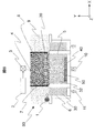
- the laser powder additive manufacturing apparatus 60 used in the present invention includes a roller 1 or a blade that supplies a powder resin 30 for supply to a modeling area, a laser light source 2 that is used to sinter or melt an installed resin powder 31 to perform lamination bonding, A galvanometer mirror 3 for moving the laser beam 4 at a high speed in the modeling area 8, a modeling container 5 in the modeling area 8, a reflector 7, and a storage container 6 for storing the powder material disposed on both sides of the modeling container 5, It is comprised from the heater (not shown) for hold
- the area temperature 9 of the container 6 for storing the powder material (powder resin) is preferably set to be equal to or lower than the temperature in the modeling area 8.
- Laminated modeling is a method in which a molded product 50 is produced three-dimensionally by spreading powder with a roller 1 or a blade, sintering or melting the resin powder 31 placed with a laser beam 4, and repeating them. After modeling, the modeled product 50 is in a state of being buried in the resin powder 32. After being taken out from the resin powder 32, the modeled product 50 is peeled from the modeled product 50 by blasting or the like.
- the modeling area 8 is preferably purged with nitrogen, argon or the like to reduce the oxygen concentration in order to suppress powder deterioration. Further, the laser light source 2 needs to be changed according to the absorption characteristics of the resin powder.
- a CO 2 laser (wavelength 10.6 ⁇ m) is generally used.
- the resin powder color includes a material that absorbs infrared light such as black, a fiber laser, a YAG laser, and a semiconductor laser (wavelength 800-1100 nm) may be used in addition to the CO 2 laser.
- the intensity distribution of the laser beam 4 is normally Gaussian, but it can be made higher definition if it is a top hat shape.
- the size of the resin powder to be used is preferably about ⁇ 10-100 ⁇ m.
- a 3D CAD model is often used for designing the object in advance in the laser powder additive manufacturing apparatus 60.
- a work procedure to be performed in each process such as each process such as an irradiation order of laser irradiation is set for each layer.
- This setting may be performed by a computer (not shown) used for design, a computer connected via a separate network or the like, and may take any form.
- the setting may be performed by the laser powder additive manufacturing apparatus 60.
- This 3D CAD model or information on the work procedure set from the 3D CAD model is stored in the storage unit of the laser powder additive manufacturing apparatus 60, and additive manufacturing is performed using the stored information.
- work procedure information, etc. means using communication from a network or the like from another computer, separate storage such as an optical disk such as a CD-ROM, MO, flash memory, etc. You may input the information of the said work procedure by transmission / reception etc. using an apparatus.
- a laser powder additive manufacturing method will be described as a representative example of the three-dimensional additive manufacturing.
- FIG. 1 is a plan view showing an embodiment of an additive manufacturing method and apparatus according to the present invention.
- powder resin powder or powder resin, but also simply called powder
- the powder is sintered to produce a thin layer, so that the sintering strength between thin layers, that is, the Z direction (vertical direction) is small.
- the powder is in close contact with the sintered portion only by its own weight before sintering with the laser beam 4, and voids between the layers are easily generated.
- the modeling area 8 during modeling is heated to 5 to 15 ° C. from the melting point of the resin material by heating with a heater or the like installed at a modeling location.
- the temperature is often set to a low temperature. This is called a process window method.
- the resin powder 31 is sufficiently wetted to the sintered part 33, it is necessary to develop a high strength, but the wettability is reduced by the bleed effect of the sintered part 33, and the strength between the thin layers is greatly reduced. And a significant increase in voids may occur.
- the present inventors have partially melted the surface by subjecting the sintered portion 33 before the resin powder 31 to installation to a surface modification treatment (hereinafter also simply referred to as “modification treatment”). It was found that the resin powder 31 sufficiently wets the sintered part 33 and greatly contributes to the improvement of strength between thin layers and the reduction of voids.
- these functional groups are generated on the surface of the sintered portion 33, the surface energy itself is greatly improved. Therefore, the surface energy of the sintered portion 33 can be increased with respect to the surface energy of the resin powder 31 to be joined, and the wettability is increased. The effect is improved.
- the portion subjected to the modification treatment generates or increases not only the surface but also oxygen functional groups in the treated region.
- a dry treatment that does not scatter the resin powder for example, an atmospheric pressure plasma treatment or a UV treatment (including UV ozone treatment) may be used to operate the resin powder 31.
- the amorphous resin is softened from the glass transition temperature, but the viscosity is not drastically lowered, and as a result, the sintered portion 33 is not wetted.
- the surface modification treatment of the present invention to the sintered portion 33, the adhesion between the sintered portion 33 and the powder irradiated with the laser is greatly improved, so that an amorphous resin can be used.
- the temperature of the modeling area 8 is often up to 200 ° C. from the viewpoint of the equipment cost, and there has been a serious limitation in the crystalline resin. Furthermore, even if the device window is allowed to increase and the process window method is adopted for the high melting point resin, the resin powders 31 and 32 are exposed to a high temperature of 200 ° C. or higher for a long time, so that the powders are partially adhered to each other. Since it becomes easy to become a cake lump (cake) and deterioration easily occurs, a significant deterioration in the recycling rate of the resin powders 31 and 32 becomes a problem.
- the support substrate 40 when using a high melting point resin, it is preferable to use the support substrate 40 in order to keep the temperature of the modeling area 8 below the recrystallization temperature and suppress warping.
- the resin subjected to the dry treatment has a very small effect at a high temperature because the generation and increase of the functional group is accelerated when left at a high temperature. Therefore, the effect of the surface modification treatment is further improved by setting the modeling temperature as low as possible (for example, 100 ° C. or lower).
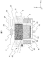
- the configuration shown in FIG. 2 is an effective method even for a resin having a low melting point and using the process window method.
- the above-mentioned quality refers to interlaminar strength and void reduction.
- the process window method since the process window method is not used, it is robust to temperature control and is effective in ensuring the quality of the large shaped product 50. Further, depending on the application target of the modeled product 50, the quality may be the same level as the process window method, and priority may be given to shortening the modeling time.
- the surface modification processing unit 20 is not built in the laser powder additive manufacturing apparatus 60, and the modeling substrate 8 is set to a relatively low temperature below the recrystallization degree, and the support substrate is subjected to surface treatment in advance. You may employ
- the overhang shape may not be applicable.
- the support 34 is preferably made of the same resin material as that of the modeled product 50 and produced with laser energy different from the formation of the modeled product 50.
- voids having a large amount and a large size are formed in the resin of the support 34.
- the void is not greatly affected by the shear stress generated during the warp and greatly depends on the impact strength. Therefore, if the impact stress is applied at the time of peeling, the void in the material of the support 34 itself. It becomes easy to destroy.
- the material of the support 34 can be easily broken as in the case where the energy is further increased.
- the material of the support substrate 40 is desirably a resin material having a rigidity and melting point higher than that of the resin material used for modeling or a metal having a relatively low thermal conductivity.
- the peeling of the support substrate 40 and the modeled product 50 can be caused to be interface failure by controlling the conditions of the surface modification treatment. Is greatly improved.
- WBL W eak B oundary L ayer
- the part or WBL joined by some surface treatment is particularly weak against moisture and solvent, so that after modeling, the molded product and the support substrate 40 can be left in a high humidity atmosphere or immersed in a solvent or moisture. Their peeling is also easy. Furthermore, since the mode that breaks at the interface greatly depends on the impact strength as compared with the shear stress generated during warping, the interface breakage is facilitated by applying the impact stress at the time of peeling.
- the shaped product 50 and the support substrate 40 be joined to the peripheral portion of the shaped product 50. Also, by providing the support substrate 40 with the holes 41, it becomes possible to directly apply a load to the molded product, and particularly the close contact portion can be subjected to a peeling stress that easily causes interfacial breakage, so that the peelability is further improved. To do.
- a metal having a relatively low thermal conductivity for example, 30 W / mK
- it is also effective to improve the peelability by applying a peeling stress after the support substrate 40 is heated to a high temperature.
- the surface roughness of the support plate material is desirably a relatively smooth state, that is, a surface roughness of Ra 0.5 ⁇ m or less, from the viewpoint of causing the interface breakage between the support substrate 40 and the shaped product 50.
- the mold should be mirror-finished, and if it is made of a material such as metal or ceramics, it should be made of abrasive paper with relatively small roughness. It is good to polish.
- the support substrate 40 having a higher thermal conductivity than that of the resin when a metal or the like is used for the support substrate 40 having a higher thermal conductivity than that of the resin, if the heater is provided at the bottom of the support substrate 40, the support substrate 40 and the resin powder 31 can be irradiated with a lower energy laser. Can be joined. Furthermore, in the case of layered modeling of a modeled object (modeling model) with a small thickness, even when the modeling area 8 is small, that is, in a state where the environmental temperature is low, it is possible to suppress warping of the modeled product 50 during modeling. .
- the surface modification processing unit 20 can cope with it by retracting in the Z direction. Further, when the surface modification processing unit 20 is operated only in the plane direction due to the configuration or the price of the laser powder additive manufacturing apparatus 60, the roller 1 and the surface modification processing unit 20 are crossed as shown in FIG. It is good to arrange and drive. In that case, for example, when the roller 1 operates in the X direction, the surface modification processing unit 20 operates in the Y direction. Of course, the reverse is also possible.
- the intersecting angle need not be exactly 90 degrees and may be changed as appropriate.
- the surface modification processing unit 20 has been described as being mechanically operated in the same manner as a roller.
- a UV laser wavelength of 300 nm or less, eg, an excimer laser
- an ultrashort pulse with a pulse width of You may use below ps (for example, titanium sapphire laser).
- a galvano mirror 24 may be installed and operated.
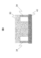
- the support 43 made of the same material may be provided on the support substrate 40 by a process as shown in FIG.
- the support 43 is manufactured by modeling, and the material may be the same as that of the modeled product 50.
- the support 43 has a relationship with the support substrate 40 employed in the overhang structure. It is desirable.
- the support 43 is directly destroyed in the process of peeling the support 43 and the molded product 50.
- the shaped article 50 and the support substrate 40 are not in close contact with each other, the laser energy used for joining the support 43 and the support substrate 40 can be increased.
- the support substrate 40 can use a metal having higher thermal conductivity (for example, 250 W / mK). When such a material is used, the releasability when the support substrate 40 is heated becomes easy. Further, it becomes possible to use the support substrate 40 having a weak oxide film strength on the surface such as Al, and the interface separation between the support substrate 40 and the support 43 becomes easier.
- a metal having higher thermal conductivity for example, 250 W / mK.
- FIG. 9 it is good to form the through-holes 41 and 44 in the support board
- the bonding area between the support 43 and the modeled product 50 be smaller than the bonding area between the support substrate 40 and the support 43.
- the rigidity of the support substrate 40 is desirably higher than the rigidity of the support 43.
- the surface roughness of the support substrate 40 be about 0.5 ⁇ m, but in the case of the present invention, the surface roughness may be increased to 7.0 ⁇ m.
- the surface roughness may be larger than 7.0 ⁇ m, only a part of the resin enters, and the strength of the support 43 and the support substrate 40 becomes weak.
- the support substrate 40 is made of resin and manufactured by injection molding, the mold may be roughened and the surface of the support substrate 40 may be formed into a textured shape.
- the support substrate 40 When the support substrate 40 is made of metal, it may be sandblasted or processed with abrasive paper having a relatively large roughness.
- the support 34 may be used in the case of an overhang shape. Further, the number of support substrates 40 and the number of supports 34 are not limited to one and may be plural depending on circumstances.
- each of the embodiments described so far can be carried out independently, but in particular, by using a surface modification treatment in combination, as shown in FIG.
- the product 50 can also be manufactured.
- the methods described so far may be combined, but it is desirable that the linear expansion coefficient between the powdered resins is as high as possible.
- a 3D CAD model is used.
- the structure of the support substrate 40 and the support 43 is software using software built into the model for modeling.
- the modeled model is modeled in consideration of the part to be peeled off, and the quality of the modeled object is further improved.
- the laser irradiation conditions vary greatly depending on the physical properties of the materials of the support substrate 40 and the support 43, the laser irradiation conditions and the material information (materials, bondability, materials related to sintering, materials related to design, etc.) It is even better to include in the software information that includes information related to modeling, not only information alone but also information configured using a plurality of information and related to modeling). The laser irradiation conditions become more suitable, and the quality of the shaped article is increased.
- the powder resin material which can employ the present invention is polyamide 12 (PA12), polyamide 11 (PA11), polyethylene (PE), polypropylene (PP), polyoxy as a crystalline resin material having a low melting point of 200 ° C. or less.
- Methylene (POM) and the like are targeted.
- polybutylene terephthalate PBT
- polyphenylene sulfide PPS
- polyamide 6 PA6
- PA66 polyamide 6T
- PA9T PA9T
- PEEK Polyether ether ketone
- LCP liquid crystal polymer
- PET polyethylene terephthalate
- PTT polytrimethylene terephthalate
- PEN polyethylene naphthalate
- PTFE polytetrafluoroethylene
- Non-crystalline resin materials include polystyrene (PS), acrylonitrile styrene (AS), acrylonitrile butadiene styrene copolymer (ABS), polymethyl methacrylate (PMMA), cycloolefin polymer (COP), and cycloolefin copolymer.
- PS polystyrene
- AS acrylonitrile styrene
- ABS acrylonitrile butadiene styrene copolymer
- PMMA polymethyl methacrylate
- COP cycloolefin polymer
- COC cycloolefin copolymer
- PVC polyvinyl chloride
- PC polycarbonate
- mPPE polycarbonate
- PEI polyphenylene ether
- PAR polyetherimide
- PAR polyarylate
- PES polysulfone
- an alloy material containing 1-30% of the non-crystalline resin in the crystalline resin is also targeted.
- the crystalline resin material may be compounded by containing 1-30% of an inorganic material such as glass, alumina, carbon material or a part of metal powder.
- an inorganic material coated with the resin material may be used.
- a main material you may apply not only to a thermoplastic resin but to thermosetting resins, such as an epoxy type and an acrylic type.
- the support substrate 40 in addition to the above crystalline resin material, SUS and Al, as well as metals (including die cast) and ceramics having a thermal conductivity of 250 W / mK or less may be used.
- the laser powder additive manufacturing method has been described as a target until now, but the present invention includes an additive manufacturing method in which molten resin is discharged from a nozzle and stacked, and an additive manufacturing method in which resin is discharged by inkjet and stacked. It is also effective for other methods and apparatuses.
Landscapes
- Engineering & Computer Science (AREA)
- Chemical & Material Sciences (AREA)
- Materials Engineering (AREA)
- Manufacturing & Machinery (AREA)
- Physics & Mathematics (AREA)
- Optics & Photonics (AREA)
- Mechanical Engineering (AREA)
- Health & Medical Sciences (AREA)
- Toxicology (AREA)
- Plasma & Fusion (AREA)
Abstract
Priority Applications (2)
| Application Number | Priority Date | Filing Date | Title |
|---|---|---|---|
| US15/110,517 US20160332370A1 (en) | 2014-03-28 | 2014-10-22 | Laser Powder Lamination Shaping Device, Laser Powder Lamination Shaping Method, and 3D Lamination Shaping Device |
| JP2016509891A JP6190038B2 (ja) | 2014-03-28 | 2014-10-22 | レーザ粉末積層造形装置及びレーザ粉末積層造形方法及び3次元積層造形装置 |
Applications Claiming Priority (2)
| Application Number | Priority Date | Filing Date | Title |
|---|---|---|---|
| JP2014-067462 | 2014-03-28 | ||
| JP2014067462 | 2014-03-28 |
Publications (1)
| Publication Number | Publication Date |
|---|---|
| WO2015145844A1 true WO2015145844A1 (fr) | 2015-10-01 |
Family
ID=54194416
Family Applications (1)
| Application Number | Title | Priority Date | Filing Date |
|---|---|---|---|
| PCT/JP2014/078014 Ceased WO2015145844A1 (fr) | 2014-03-28 | 2014-10-22 | Dispositif de formage laser par stratification de poudre, procédé de formage laser par stratification de poudre et dispositif de formage par stratification 3d |
Country Status (3)
| Country | Link |
|---|---|
| US (1) | US20160332370A1 (fr) |
| JP (1) | JP6190038B2 (fr) |
| WO (1) | WO2015145844A1 (fr) |
Cited By (18)
| Publication number | Priority date | Publication date | Assignee | Title |
|---|---|---|---|---|
| CN105522155A (zh) * | 2016-03-03 | 2016-04-27 | 中研智能装备有限公司 | 一种火车轮等离子3d快速成型再制造设备及方法 |
| CN105710371A (zh) * | 2016-03-03 | 2016-06-29 | 中研智能装备有限公司 | 一种火车轮等离子3d打印再制造设备及方法 |
| CN106180710A (zh) * | 2016-07-14 | 2016-12-07 | 武汉鑫双易科技开发有限公司 | 基于等离子体电弧熔覆的3d金属增材制造装置及方法 |
| JP2017075364A (ja) * | 2015-10-15 | 2017-04-20 | セイコーエプソン株式会社 | 三次元造形物の製造方法及び三次元造形物の製造装置 |
| US20170209929A1 (en) * | 2016-01-22 | 2017-07-27 | Seiko Epson Corporation | Three-dimensional shaped article production method |
| WO2017126484A1 (fr) * | 2016-01-20 | 2017-07-27 | 東レ株式会社 | Article granuleux en résine de poly(sulfure d'arylène) et son procédé de production |
| WO2017221913A1 (fr) * | 2016-06-22 | 2017-12-28 | パナソニックIpマネジメント株式会社 | Procédé de fabrication d'objet moulé de forme tridimensionnelle |
| WO2017221912A1 (fr) * | 2016-06-22 | 2017-12-28 | パナソニックIpマネジメント株式会社 | Procédé de fabrication d'objet moulé de forme tridimensionnelle |
| JP2018196953A (ja) * | 2017-05-24 | 2018-12-13 | 株式会社リコー | 立体造形用サポート材、立体造形用モデル材及び立体造形用サポート材のセット、立体造形物の製造方法、並びに立体造形装置 |
| JP2019510094A (ja) * | 2016-01-21 | 2019-04-11 | スリーエム イノベイティブ プロパティズ カンパニー | フルオロポリマーの積層プロセス |
| JP2019526704A (ja) * | 2016-08-10 | 2019-09-19 | レニショウ パブリック リミテッド カンパニーRenishaw Public Limited Company | 付加製造を含む方法およびシステム、ならびに付加製造された物品 |
| WO2019189347A1 (fr) | 2018-03-30 | 2019-10-03 | 株式会社アスペクト | Objet moulé fondu à lit de poudre et son procédé de production |
| JP2020518485A (ja) * | 2017-04-28 | 2020-06-25 | ダイバージェント テクノロジーズ, インコーポレイテッドDivergent Technologies, Inc. | 付加製造における支持構造 |
| WO2020188648A1 (fr) * | 2019-03-15 | 2020-09-24 | 株式会社ニコン | Procédé de modélisation, système de modélisation et base de modélisation |
| JP2021006658A (ja) * | 2019-06-03 | 2021-01-21 | ザ・ボーイング・カンパニーThe Boeing Company | 付加製造粉末粒子、付加製造粉末粒子を処理する方法、および付加製造方法 |
| US11154933B2 (en) | 2015-12-17 | 2021-10-26 | Seiko Epson Corporation | Three-dimensional shaped article production method, three-dimensional shaped article production apparatus, and three-dimensional shaped article |
| US11267052B2 (en) | 2014-11-21 | 2022-03-08 | Renishaw Plc | Additive manufacturing apparatus and methods |
| US11925981B2 (en) * | 2020-06-29 | 2024-03-12 | Arcam Ab | Method, apparatus and control unit for selectively sintering a powder layer in additive manufacturing processes to achieve a future, desired heat conductivity |
Families Citing this family (13)
| Publication number | Priority date | Publication date | Assignee | Title |
|---|---|---|---|---|
| US10029421B2 (en) * | 2014-09-18 | 2018-07-24 | 3Dm Digital Manufacturing Ltd | Device and a method for 3D printing and manufacturing of materials using quantum cascade lasers |
| JP6825333B2 (ja) * | 2016-11-28 | 2021-02-03 | 株式会社リコー | 立体造形物の製造方法、及び立体造形物の製造装置 |
| AT15637U1 (de) * | 2017-01-17 | 2018-03-15 | Univ Innsbruck | Verfahren zur additiven Fertigung |
| JP6961972B2 (ja) * | 2017-03-24 | 2021-11-05 | 富士フイルムビジネスイノベーション株式会社 | 立体形状成形装置、情報処理装置及びプログラム |
| ES2954332T3 (es) * | 2017-11-16 | 2023-11-21 | Mutsuki Electric Co Ltd | Método para producir un miembro metálico y método para producir un cuerpo unido de metal-resina |
| WO2019108200A1 (fr) | 2017-11-30 | 2019-06-06 | Hewlett-Packard Development Company, L.P. | Agent anticoalescent pour impression en trois dimensions |
| JP7067134B2 (ja) * | 2018-03-07 | 2022-05-16 | 株式会社ジェイテクト | 積層造形装置の造形方法及び積層造形装置 |
| US11577458B2 (en) * | 2018-06-29 | 2023-02-14 | 3M Innovative Properties Company | Additive layer manufacturing method and articles |
| RU2705821C1 (ru) * | 2018-08-10 | 2019-11-12 | Федеральное государственное бюджетное образовательное учреждение высшего образования Балтийский государственный технический университет "ВОЕНМЕХ" им. Д.Ф. Устинова (БГТУ "ВОЕНМЕХ") | Способ лазерного послойного синтеза объемного изделия с внутренними каналами |
| US10926325B2 (en) * | 2018-09-28 | 2021-02-23 | The Boeing Company | Methods and apparatus for additively manufacturing a structure with in-situ reinforcement |
| US10926461B2 (en) * | 2018-09-28 | 2021-02-23 | The Boeing Company | Methods and apparatus for additively manufacturing a structure with in-situ reinforcement |
| US10926460B2 (en) * | 2018-09-28 | 2021-02-23 | The Boeing Company | Methods and apparatus for additively manufacturing a structure with in-situ reinforcement |
| CN116000311B (zh) * | 2021-10-21 | 2024-10-01 | 中国科学院沈阳自动化研究所 | 一种激光增材制造大尺寸镜面模具的表面完整性控制方法 |
Citations (6)
| Publication number | Priority date | Publication date | Assignee | Title |
|---|---|---|---|---|
| JPH09506553A (ja) * | 1995-03-20 | 1997-06-30 | イーオーエス ゲゼルシャフト ミット ベシュレンクテル ハフツング イレクトロ オプティカル システムズ | レーザー焼結による3次元物体の製造装置および方法 |
| JP2004074800A (ja) * | 2002-08-09 | 2004-03-11 | Eos Gmbh Electro Optical Systems | 三次元物体の製造方法及び装置 |
| JP2006045584A (ja) * | 2004-07-30 | 2006-02-16 | Media Plus Inc | 積層造形方法 |
| JP2010527810A (ja) * | 2007-05-25 | 2010-08-19 | イーオーエス ゲゼルシャフト ミット ベシュレンクテル ハフツング イレクトロ オプティカル システムズ | 三次元物体の層状製造方法 |
| JP2011173420A (ja) * | 2010-02-23 | 2011-09-08 | Eos Gmbh Electro Optical Systems | 微細技術に適した三次元物体を製造する方法および装置 |
| JP2012096428A (ja) * | 2010-11-01 | 2012-05-24 | Keyence Corp | 三次元造形装置及び三次元造形方法 |
-
2014
- 2014-10-22 WO PCT/JP2014/078014 patent/WO2015145844A1/fr not_active Ceased
- 2014-10-22 JP JP2016509891A patent/JP6190038B2/ja not_active Expired - Fee Related
- 2014-10-22 US US15/110,517 patent/US20160332370A1/en not_active Abandoned
Patent Citations (6)
| Publication number | Priority date | Publication date | Assignee | Title |
|---|---|---|---|---|
| JPH09506553A (ja) * | 1995-03-20 | 1997-06-30 | イーオーエス ゲゼルシャフト ミット ベシュレンクテル ハフツング イレクトロ オプティカル システムズ | レーザー焼結による3次元物体の製造装置および方法 |
| JP2004074800A (ja) * | 2002-08-09 | 2004-03-11 | Eos Gmbh Electro Optical Systems | 三次元物体の製造方法及び装置 |
| JP2006045584A (ja) * | 2004-07-30 | 2006-02-16 | Media Plus Inc | 積層造形方法 |
| JP2010527810A (ja) * | 2007-05-25 | 2010-08-19 | イーオーエス ゲゼルシャフト ミット ベシュレンクテル ハフツング イレクトロ オプティカル システムズ | 三次元物体の層状製造方法 |
| JP2011173420A (ja) * | 2010-02-23 | 2011-09-08 | Eos Gmbh Electro Optical Systems | 微細技術に適した三次元物体を製造する方法および装置 |
| JP2012096428A (ja) * | 2010-11-01 | 2012-05-24 | Keyence Corp | 三次元造形装置及び三次元造形方法 |
Cited By (28)
| Publication number | Priority date | Publication date | Assignee | Title |
|---|---|---|---|---|
| US11267052B2 (en) | 2014-11-21 | 2022-03-08 | Renishaw Plc | Additive manufacturing apparatus and methods |
| JP2017075364A (ja) * | 2015-10-15 | 2017-04-20 | セイコーエプソン株式会社 | 三次元造形物の製造方法及び三次元造形物の製造装置 |
| US11154933B2 (en) | 2015-12-17 | 2021-10-26 | Seiko Epson Corporation | Three-dimensional shaped article production method, three-dimensional shaped article production apparatus, and three-dimensional shaped article |
| EP3181271B1 (fr) * | 2015-12-17 | 2024-07-17 | Seiko Epson Corporation | Procédé de production d'articles tridimensionnels, appareil de production d'articles tridimensionnels et article tridimensionnel |
| JPWO2017126484A1 (ja) * | 2016-01-20 | 2018-01-25 | 東レ株式会社 | ポリアリーレンスルフィド樹脂粉粒体およびその製造方法 |
| WO2017126484A1 (fr) * | 2016-01-20 | 2017-07-27 | 東レ株式会社 | Article granuleux en résine de poly(sulfure d'arylène) et son procédé de production |
| US11008426B2 (en) | 2016-01-20 | 2021-05-18 | Toray Industries, Inc. | Polyarylene sulfide resin particulate and method of producing same |
| JP2019510094A (ja) * | 2016-01-21 | 2019-04-11 | スリーエム イノベイティブ プロパティズ カンパニー | フルオロポリマーの積層プロセス |
| CN106994515A (zh) * | 2016-01-22 | 2017-08-01 | 精工爱普生株式会社 | 三维造型物的制造方法 |
| US20170209929A1 (en) * | 2016-01-22 | 2017-07-27 | Seiko Epson Corporation | Three-dimensional shaped article production method |
| US10814389B2 (en) * | 2016-01-22 | 2020-10-27 | Seiko Epson Corporation | Three-dimensional shaped article production method |
| CN106994515B (zh) * | 2016-01-22 | 2021-05-11 | 精工爱普生株式会社 | 三维造型物的制造方法 |
| CN105522155A (zh) * | 2016-03-03 | 2016-04-27 | 中研智能装备有限公司 | 一种火车轮等离子3d快速成型再制造设备及方法 |
| CN105710371A (zh) * | 2016-03-03 | 2016-06-29 | 中研智能装备有限公司 | 一种火车轮等离子3d打印再制造设备及方法 |
| WO2017221913A1 (fr) * | 2016-06-22 | 2017-12-28 | パナソニックIpマネジメント株式会社 | Procédé de fabrication d'objet moulé de forme tridimensionnelle |
| JPWO2017221913A1 (ja) * | 2016-06-22 | 2019-03-22 | パナソニックIpマネジメント株式会社 | 三次元形状造形物の製造方法 |
| WO2017221912A1 (fr) * | 2016-06-22 | 2017-12-28 | パナソニックIpマネジメント株式会社 | Procédé de fabrication d'objet moulé de forme tridimensionnelle |
| JPWO2017221912A1 (ja) * | 2016-06-22 | 2019-03-14 | パナソニックIpマネジメント株式会社 | 三次元形状造形物の製造方法 |
| CN106180710A (zh) * | 2016-07-14 | 2016-12-07 | 武汉鑫双易科技开发有限公司 | 基于等离子体电弧熔覆的3d金属增材制造装置及方法 |
| JP2019526704A (ja) * | 2016-08-10 | 2019-09-19 | レニショウ パブリック リミテッド カンパニーRenishaw Public Limited Company | 付加製造を含む方法およびシステム、ならびに付加製造された物品 |
| JP2020518485A (ja) * | 2017-04-28 | 2020-06-25 | ダイバージェント テクノロジーズ, インコーポレイテッドDivergent Technologies, Inc. | 付加製造における支持構造 |
| JP2018196953A (ja) * | 2017-05-24 | 2018-12-13 | 株式会社リコー | 立体造形用サポート材、立体造形用モデル材及び立体造形用サポート材のセット、立体造形物の製造方法、並びに立体造形装置 |
| WO2019189347A1 (fr) | 2018-03-30 | 2019-10-03 | 株式会社アスペクト | Objet moulé fondu à lit de poudre et son procédé de production |
| WO2020188648A1 (fr) * | 2019-03-15 | 2020-09-24 | 株式会社ニコン | Procédé de modélisation, système de modélisation et base de modélisation |
| JP2021006658A (ja) * | 2019-06-03 | 2021-01-21 | ザ・ボーイング・カンパニーThe Boeing Company | 付加製造粉末粒子、付加製造粉末粒子を処理する方法、および付加製造方法 |
| US12017404B2 (en) | 2019-06-03 | 2024-06-25 | The Boeing Company | Additive manufacturing powder particle, method for treating the additive manufacturing powder particle, and method for additive manufacturing |
| JP7538620B2 (ja) | 2019-06-03 | 2024-08-22 | ザ・ボーイング・カンパニー | 付加製造粉末粒子、付加製造粉末粒子を処理する方法、および付加製造方法 |
| US11925981B2 (en) * | 2020-06-29 | 2024-03-12 | Arcam Ab | Method, apparatus and control unit for selectively sintering a powder layer in additive manufacturing processes to achieve a future, desired heat conductivity |
Also Published As
| Publication number | Publication date |
|---|---|
| US20160332370A1 (en) | 2016-11-17 |
| JPWO2015145844A1 (ja) | 2017-04-13 |
| JP6190038B2 (ja) | 2017-08-30 |
Similar Documents
| Publication | Publication Date | Title |
|---|---|---|
| JP6190038B2 (ja) | レーザ粉末積層造形装置及びレーザ粉末積層造形方法及び3次元積層造形装置 | |
| JP6178933B2 (ja) | 物体をモールド成形及び複製するための熱溶解積層法に基づく鋳型、その製造のための方法及び熱溶解積層式3dプリンタ | |
| JP6808816B2 (ja) | 造形材料粒子の積層 | |
| JP6384826B2 (ja) | 三次元積層造形装置、三次元積層造形方法および三次元積層造形プログラム | |
| CN104708809A (zh) | 立体打印装置 | |
| JP2013022965A (ja) | 三次元の物体を層状に製造するための装置と方法及びモールド | |
| JP6798269B2 (ja) | 樹脂成形装置および樹脂成形方法 | |
| CN103660298A (zh) | 用于借助冷却元件逐层地制造变形小的三维物体的方法 | |
| JP2013022964A (ja) | 三次元の物体を層状に製造するための装置と方法、ポリマー粉末及びモールド | |
| CN110366465A (zh) | 三维造型物制造用组合物、三维造型物的制造方法以及三维造型物制造装置 | |
| JP6888259B2 (ja) | 積層造形構造体、積層造形方法および積層造形装置 | |
| JP7137229B2 (ja) | 樹脂成形方法 | |
| US20220168968A1 (en) | Resin molding method | |
| JP2004142427A (ja) | 三次元形状造形物の製造方法 | |
| CN104908316A (zh) | 成型方法及成型系统 | |
| JP7137228B2 (ja) | 樹脂成形方法 | |
| CN108068310A (zh) | 立体打印方法 | |
| WO2022107307A1 (fr) | Procédé de production et dispositif de production pour objet fabriqué en trois dimensions | |
| JP7446794B2 (ja) | 三次元造形物の製造方法、および三次元造形装置 | |
| JP2016155337A (ja) | 積層造形装置および積層造形方法 | |
| KR102028599B1 (ko) | 3d 프린트 출력물에 기능성 물질층을 전사하는 방법 | |
| US20240399663A1 (en) | Hybrid manufacturing and electronic devices made thereby | |
| KR101456830B1 (ko) | 삼차원 물체 제조장치 및 제조방법 | |
| JP7358821B2 (ja) | 積層造形装置および積層造形方法 | |
| JP6699255B2 (ja) | 積層造形装置および積層造形方法 |
Legal Events
| Date | Code | Title | Description |
|---|---|---|---|
| 121 | Ep: the epo has been informed by wipo that ep was designated in this application |
Ref document number: 14887645 Country of ref document: EP Kind code of ref document: A1 |
|
| ENP | Entry into the national phase |
Ref document number: 2016509891 Country of ref document: JP Kind code of ref document: A |
|
| WWE | Wipo information: entry into national phase |
Ref document number: 15110517 Country of ref document: US |
|
| NENP | Non-entry into the national phase | ||
| 122 | Ep: pct application non-entry in european phase |
Ref document number: 14887645 Country of ref document: EP Kind code of ref document: A1 |