EP2447399A2 - Procédé de tricotage en utilisant un métier à tricoter rectiligne avec plusieurs guide-fills et un tricot correspondent - Google Patents
Procédé de tricotage en utilisant un métier à tricoter rectiligne avec plusieurs guide-fills et un tricot correspondent Download PDFInfo
- Publication number
- EP2447399A2 EP2447399A2 EP11008526A EP11008526A EP2447399A2 EP 2447399 A2 EP2447399 A2 EP 2447399A2 EP 11008526 A EP11008526 A EP 11008526A EP 11008526 A EP11008526 A EP 11008526A EP 2447399 A2 EP2447399 A2 EP 2447399A2
- Authority
- EP
- European Patent Office
- Prior art keywords
- knitting
- knitted fabric
- yarn
- yarn feeder
- fabric portion
- Prior art date
- Legal status (The legal status is an assumption and is not a legal conclusion. Google has not performed a legal analysis and makes no representation as to the accuracy of the status listed.)
- Granted
Links
Images


Classifications
-
- D—TEXTILES; PAPER
- D04—BRAIDING; LACE-MAKING; KNITTING; TRIMMINGS; NON-WOVEN FABRICS
- D04B—KNITTING
- D04B1/00—Weft knitting processes for the production of fabrics or articles not dependent on the use of particular machines; Fabrics or articles defined by such processes
- D04B1/10—Patterned fabrics or articles
- D04B1/12—Patterned fabrics or articles characterised by thread material
- D04B1/126—Patterned fabrics or articles characterised by thread material with colour pattern, e.g. intarsia fabrics
-
- D—TEXTILES; PAPER
- D10—INDEXING SCHEME ASSOCIATED WITH SUBLASSES OF SECTION D, RELATING TO TEXTILES
- D10B—INDEXING SCHEME ASSOCIATED WITH SUBLASSES OF SECTION D, RELATING TO TEXTILES
- D10B2403/00—Details of fabric structure established in the fabric forming process
- D10B2403/03—Shape features
- D10B2403/033—Three dimensional fabric, e.g. forming or comprising cavities in or protrusions from the basic planar configuration, or deviations from the cylindrical shape as generally imposed by the fabric forming process
- D10B2403/0333—Three dimensional fabric, e.g. forming or comprising cavities in or protrusions from the basic planar configuration, or deviations from the cylindrical shape as generally imposed by the fabric forming process with tubular portions of variable diameter or distinct axial orientation
Definitions
- the present invention relates to a knitting method of a knitted fabric for arranging a cross-over yarn portion, which connects knitted fabric portions, on the back side of a knitted fabric when knitting the knitted fabric including two knitted fabric portions that are knitted with the same knitting yarn spaced apart in a wale direction of the knitted fabric such as a striped sweater, and a knitted fabric knitted using such knitting method.
- Knitting one knitted fabric using a plurality of knitting yarns of different colors with a flat knitting machine having at least a pair of front and back needle beds has been carried out from the related art.
- a typical example is knitting a striped tubular knitted fabric of a horizontal-striped pattern.
- circling knitting or C-shaped flechage knitting is carried out for a few courses with a knitting yarn (e.g., white) fed from a first yarn feeder arranged in the flat knitting machine to knit a knitted fabric portion, which is one of the stripes in the striped pattern.
- the circling knitting or the C-shaped flechage knitting is then carried out for a few courses with a knitting yarn (e.g., blue) fed from a second yarn feeder in continuation to the wale direction of the knitted fabric portion to form a knitted fabric portion that configures the next stripe in the striped pattern.
- the knitting with the knitting yarn (white) fed from the first yarn feeder and the knitting with the knitting yarn (blue) fed from the second yarn feeder are repeated to complete the striped knitted fabric having a horizontal-striped pattern.
- the second yarn feeder is a far side yarn feeder that is on the far side when seen from the front needle bed (hereinafter referred to as FB), that is, the back needle bed (hereinafter referred to as BB) side
- the first yarn feeder is a near side yarn feeder that is on the near side when seen from FB when starting the knitting of a knitted fabric portion (hereinafter referred to as intermediate knitted fabric portion) using the second yarn feeder following in the wale direction of a knitted fabric portion (hereinafter referred to as lower knitted fabric portion) knitted with the first yarn feeder.
- the knitting yarn extending from the near side yarn feeder is arranged on the outer side of the tube of an intermediate stitch row to be knitted while knitting the intermediate stitch row.
- a knitted fabric portion hereinafter referred to as upper knitted fabric portion
- the cross-over yarn portion that connects the lower knitted fabric portion and the upper knitted fabric portion and crosses the intermediate knitted fabric portion will be arranged on the outer side of the tube of the tubular knitted fabric.
- Patent document 1 A technique of Patent document 1 is proposed for the technique of solving such problem.
- the C-shaped flechage knitting is carried out when knitting the intermediate knitted fabric portion with the second yarn feeder so that the knitting yarn extending from the first yarn feeder is always arranged on the inner side of the tube of the intermediate knitted fabric portion.
- the cross-over yarn portion connecting the lower knitted fabric portion and the upper knitted fabric portion is thus arranged on the inner side of the tube of the tubular knitted fabric, as shown in Fig. 1 and Fig. 3 of Patent document 1.
- the cross-over yarn portion connecting the lower knitted fabric portion and the upper knitted fabric portion which are at positions spaced apart in the wale direction of the knitted fabric is in a free state on the inner side of the tube of the tubular knitted fabric.
- the cross-over yarn portion is long, such cross-over yarn portion may get caught on the wearer when the wearer wears the tubular knitted fabric.
- the development of the knitting method of the knitted fabric in which the cross-over yarn portion does not become a free state is thus desired.
- one object of the present invention is to provide a knitting method of a knitted fabric enabling knitting while preventing a cross-over yarn portion, which connects two knitted fabric portions at positions spaced apart in the wale direction of the knitted fabric, from becoming a free state, and a knitted fabric knitted by applying such knitting method of the knitted fabric.
- the present invention is a knitting method of a knitted fabric in which a lower knitted fabric portion on a lower side in a wale direction of a knitted fabric is knitted using a first yarn feeder, which is one of a plurality of yarn feeders, an intermediate knitted fabric portion continuing to an upper side in the wale direction of the lower knitted fabric portion is knitted using a second yarn feeder, which is a yarn feeder different from the first yarn feeder, and an upper knitted fabric portion continuing to an upper side in the wale direction of the intermediate knitted fabric portion is knitted using again the first yarn feeder when knitting the knitted fabric using a flat knitting machine having at least one needle bed and a plurality of yarn feeders for feeding a knitting yarn to knitting needles of the needle bed.
- the second yarn feeder is a far side yarn feeder on a far side seen from a target needle bed and the first yarn feeder is a near side yarn feeder on a near side seen from the target needle bed with respect to the target needle bed on which knitting is carried out when knitting the intermediate knitted fabric portion using either the front or the back needle bed, or when knitting the intermediate knitted fabric portion using both the front and back needle beds
- the following steps are carried out when knitting a unit stitch row for one course of the intermediate knitted fabric portion in a series in a longitudinal direction of the target needle bed.
- Step A knitting a preceding stitch row, which is one part of the unit stitch row, with a knitting yarn from the far side yarn feeder so that a knitting yarn from the near side yarn feeder is not hooked by the knitting yarn from the far side yarn feeder.
- Step B moving the near side yarn feeder in a direction opposite to the direction of forming the preceding stitch row in step A so that the knitting yarn extending from the near side yarn feeder intersect at an upper side of a needle bed gap of the knitting yarn extending from the far side yarn feeder.
- Step C after step B, knitting a trailing stitch row, which is the rest of the preceding stitch row, of the unit stitch row knitted with the target needle bed.
- the knitted fabric in the present invention is not limited to the tubular knitted fabric knitted using both the front needle bed and the back needle bed. While the knitting method of the knitted fabric of the present invention has been contrived from the problems in the tubular knitted fabric, it can also be applied to a single layer knitted fabric (e.g., handkerchief) knitted using either one of the front and back needle beds without any problems.
- a single layer knitted fabric e.g., handkerchief
- a position of tangling the knitting yarn extending from the near side yarn feeder and the knitting yarn extending from the far side yarn feeder can be shifted in a knitting width direction of the knitted fabric between the unit stitch rows adjoining in the wale direction.
- the knitted fabric to be knitted can be a tubular knitted fabric.
- the knitted fabric of the present invention is a knitted fabric knitted using a flat knitting machine having at least one needle bed and a plurality of yarn feeders for feeding a knitting yarn to knitting needles of the needle bed, the knitted fabric including three knitted fabric portions continuing in a wale direction of the knitted fabric.
- the knitted fabric of the present invention assuming the three knitted fabric portions in the knitted fabric are a lower knitted fabric portion, an intermediate knitted fabric portion, and an upper knitted fabric portion in order from a lower side of the wale direction, the lower knitted fabric portion and the upper knitted fabric portion are formed by one knitting yarn.
- a cross-over yarn portion connecting a stitch at a termination of the lower knitted fabric portion and a stitch at a starting end of the upper knitted fabric portion of the knitting yarn configuring the lower knitted fabric portion and the upper knitted fabric portion goes out from a back side to a front side and again to the back side of the intermediate knitted fabric portion to be tangled to a sinker loop of each stitch row lined in the wale direction configuring the intermediate knitted fabric portion.
- the "back side of the intermediate knitted fabric portion" in the knitted fabric of the present invention is the inner side of the tube if the knitted fabric to be finished is a tubular knitted fabric and the side in which the back stitches are formed more than the front stitches if the knitted fabric portion to be finished is a single layer knitted fabric.
- the knitted fabric of the present invention knitted with the cross-over yarn portion, which connects the lower knitted fabric portion and the upper knitted fabric portion, tangled to the intermediate knitted fabric portion at the back side of the intermediate knitted fabric portion can be knitted.
- the cross-over yarn portion does not become a free state at the back side of the intermediate knitted fabric portion, whereby the cross-over yarn portion does not get caught on the wearer when the wearer wears the knitted fabric.
- Embodiments of the present invention will be hereinafter described based on the drawings.
- a knitting example using a two-bed flat knitting machine having at least a pair of front and back needle beds, and a plurality of yarn feeders, attached to travel on a plurality of rails arranged in parallel in a longitudinal direction of the needle beds, for supplying a knitting yarn to knitting needles of the needle beds will be described.
- the knitting of the embodiment of the present invention may, of course, be carried out using a two-bed flat knitting machine equipped with a transfer jack bed or a four-bed flat knitting machine besides the two-bed flat knitting machine.
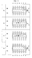
- Figs. 1 to 4 are knitting process diagrams for knitting the striped sweater with a knitting yarn from a yarn feeder 8 indicated with ⁇ and a knitting yarn (knitting yarn of different color or type from yarn feeder 8) from a yarn feeder 9 indicated with ⁇ .
- the "alphabet + number" on the left side of the figure indicates the number of the knitting process
- the black dot indicates the knitting needle arranged in the FB and the BB
- a to G indicate the positions of the knitting needles of the needle bed
- the portion where the knitting operation is actually carried out is indicated with a thick line. In each knitting process shown in the figures, the knitting approximately advances in the clockwise direction.
- the illustrated knitting process may include an area in some part where the knitting needle that is actually of the same needle bed is displayed shifted in the up and down direction in the plane of drawing for the sake of convenience of explanation (e.g., knitting needle G of FB in S3 of Fig. 1 ).
- the yarn feeder 9 becomes the far side yarn feeder at the position on the far side of the yarn feeder 8 with respect to the FB (target needle bed).
- the knitting yarn extending from the yarn feeder 8 is arranged on the outer side of the tube of the intermediate knitted fabric portion, as previously described in the description of the related art in the present specification.
- the knitting method of the knitted fabric of the present invention is implemented, as will be shown in the subsequent knitting processes. Problems do not arise in increasing the knitting course in the BB since the yarn feeder 9 is the near side yarn feeder with respect to the BB, and it is not the target needle bed defined in the claims of the present invention.
- the yarn feeder 8 is first moved towards the left in the plane of drawing, and then a stitch is formed on the knitting needle G of the FB while also moving the yarn feeder 9 towards the left side in the plane of drawing.
- the stitch formed on the knitting needle G of the FB is a preceding stitch row, which is one part of a unit stitch row (stitch row for one course in FB, and does not include stitch row in BB) for one course of the intermediate knitted fabric portion knitted with the FB.
- the knitting yarn extending from the yarn feeder 8 will not be arranged on the FB side (i.e., outer side of tube) of the preceding stitch row by carrying out the knitting of the preceding stitch row by the yarn feeder 9 only on the knitting needle G of the FB.
- the yarn feeder 8 and the yarn feeder 9 are both moved towards the right side in the plane of drawing, and stopped at the right side in the plane of drawing of the stitch of the knitting needle G, which is the stitch of the termination of the preceding stitch row.
- Either one of the yarn feeder 8 and the yarn feeder 9 may be moved first.
- the yarn feeder 9 that has finished knitting the preceding stitch row may be moved towards the right side in the plane of drawing and then the yarn feeder 8 may be moved towards the right side in the plane of drawing, or vice versa.
- the knitting yarn extending from the yarn feeder 8 on the near side with respect to the FB intersects at the upper side of the needle bed gap of the knitting yarn extending from the yarn feeder 9 on the far side with respect to the FB.
- a stitch row (trailing stitch row) is formed on the knitting needles F to A of the FB while moving the yarn feeder 9 towards the left in the plane of drawing, and thereafter, a stitch row is formed on the knitting needles A to G of the BB while moving the yarn feeder 9 towards the right in the plane of drawing.
- the knitting yarn cross-over yarn portion 7 extending from the yarn feeder 8 is arranged on the inner side of the tube, and hooked to a sinker loop (sinker loop connecting the stitch of the knitting needle G of the FB and the stitch of the knitting needle F of the FB) of the unit stitch row knitted with the yarn feeder 9 so as to go out from the inner side to the outer side and again to the inner side of the tube.
- the portion hooked to the sinker loop in the cross-over yarn portion 7 is pulled towards the inner side of the tube and is barely visible from the outer side of the tube.
- the yarn feeder 8 and the yarn feeder 9 are both moved towards the right side in the plane of drawing, and stopped at the right side in the plane of drawing of the stitch of the knitting needle F, which is the stitch of termination of the preceding stitch row. Similar to S3, either one of the movement of the yarn feeder 8 and the movement of the yarn feeder 9 in S6 may be carried out first. In either case, the knitting yarn extending from the yarn feeder 8 intersects at the upper side of the needle bed gap of the knitting yarn extending from the yarn feeder 9.
- stitches are formed on the knitting needles E to A of the FB while moving the yarn feeder 9 towards the left in the plane of drawing, and thereafter, stitches are formed on the knitting needles A to G of the BB while moving the yarn feeder 9 towards the right in the plane of drawing.
- the knitting yarn cross-over yarn portion 7 extending from the yarn feeder 8 is arranged on the inner side of the tube, and hooked to a sinker loop (sinker loop connecting the stitch of the knitting needle E of the FB and the stitch of the knitting needle F of the FB) of the unit stitch row knitted with the yarn feeder 9 so as to go out from the inner side to the outer side and again to the inner side of the tube.
- the position at where the knitting yarn of the yarn feeder 8 and the knitting yarn of the yarn feeder 9 are tangled in S5 to S7 of Fig. 2 is shifted in the knitting width direction with respect to the position at where the knitting yarn of the yarn feeder 8 and the knitting yarn of the yarn feeder 9 are tangled in S2 to S4 of Fig. 1 because the cross-over yarn portion 7 will be arranged on the outer side of the tube if the position at where the knitting yarns of the yarn feeders 8, 9 is tangled are the same position in the knitting width direction between the unit stitch rows adjoining in the wale direction.
- the problem that the cross-over yarn portion 7 is arranged on the outer side of the tube depending on the position where the knitting yarns of the yarn feeders 8, 9 are tangled arises because the yarn feeder 9 is subjected to the circling knitting in one direction (clockwise direction in the present embodiment) during the knitting of the intermediate knitted fabric portion.
- the tangling position is the same position in the knitting width direction between the unit stitch rows adjoining in the wale direction.
- the knitting of the knitted fabric portion (upper knitted fabric portion) following in the wale direction of the intermediate knitted fabric portion is started using the yarn feeder 8 used to knit the lower knitted fabric portion.
- the cross-over yarn portion 7 connecting the lower knitted fabric portion and the upper knitted fabric portion then can be arranged on the back side of the intermediate knitted fabric portion, that is, the inner side of the tube, and can be hooked and fixed to each course of the intermediate knitted fabric portion.
- the yarn feeder 8 for knitting the upper knitted fabric portion now becomes the far side yarn feeder at a position on the far side of the yarn feeder 9 with respect to the BB. That is, the BB now becomes the target needle bed defined in the claims of the present invention.
- the knitting method of the knitted fabric of the present invention is applied with the intermediate knitted fabric portion knitted using the yarn feeder 9 in Figs. 1 and 2 redefined as the lower knitted fabric portion, and the upper knitted fabric portion to be knitted using the yarn feeder 8 in Figs. 3 and 4 defined as the intermediate knitted fabric portion.
- the yarn feeder 8 on the far side of the yarn feeder 9 with respect to the BB is arranged near the yarn feeder 9.
- the knitted fabric portion (intermediate knitted fabric portion) following in the wale direction of the lower knitted fabric portion knitted with the yarn feeder 9 is knitted from the state of T1 with the knitting yarn fed from the yarn feeder 8.
- the knitting by the yarn feeder 8 is started from the knitting needle G of the FB.
- the yarn feeder 8 is first moved towards the left in the plane of drawing to form the stitch row on the knitting needles G to A of the FB, and then the yarn feeder 8 is moved towards the right in the plane of drawing to knit the stitch row on the knitting needles A to F of the BB.
- the stitch row formed on the knitting needles A to F of the BB is the preceding stitch row, which is one part of the unit stitch row of the intermediate knitted fabric portion knitted with the BB.
- the knitting yarn extending from the yarn feeder 9 is prevented from being arranged on the BB side (i.e., outer side of tube) of the preceding stitch row by carrying out the knitting of the preceding stitch row by the yarn feeder 8 only up to the needle F of the BB.
- the yarn feeder 8 that has finished the knitting of the preceding stitch row is moved towards the left side in the plane of drawing, and thereafter, the yarn feeder 9 is moved towards the left side in the plane of drawing and the knitting yarn extending from the yarn feeder 9 on the near side with respect to the BB intersects at the upper side of the needle bed gap of the knitting yarn extending from the yarn feeder 8 on the far side with respect to the BB.
- a stitch row (trailing stitch row) is formed on the knitting needle G of the BB while moving the yarn feeder 8 towards the right in the plane of drawing.
- the knitting yarn cross-over yarn portion 7) extending from the yarn feeder 9 is arranged on the inner side of the tube, and hooked to a sinker loop (sinker loop connecting the stitch of the knitting needle G of the BB and the stitch of the knitting needle F of the BB) of the unit stitch row knitted with the yarn feeder 8 so as to go out from the inner side to the outer side and again to the inner side of the tube.
- T5 the yarn feeder 9 is moved towards the right in the plane of drawing, and stopped on the right side in the plane of drawing of the knitting needle G.
- T5 is the knitting operation carried out so that the knitting yarn from the yarn feeder 9 is not knitted into the stitch row when forming the relevant stitch row on the FB using the yarn feeder 8 in T6 of Fig. 4 .
- T6 to T9 of Fig. 4 the knitting substantially similar to T2 to T5 of Fig. 3 is carried out.
- the difference lies in that the position to tangle the knitting yarn from the yarn feeder 8 and the knitting yarn from the yarn feeder 9 is shifted towards the left in the plane of drawing.
- the yarn feeder 8 is moved towards the left in the plane of drawing to form the stitch row on the knitting needles G to A of the FB, and then the yarn feeder 8 is moved towards the right in the plane of drawing to knit the stitch row on the knitting needles A to E of the BB.
- the stitch row formed on the knitting needles A to E of the BB is the preceding stitch row in this knitting course.
- the yarn feeder 8 that has finished the knitting of the preceding stitch row is moved towards the left side in the plane of drawing, and thereafter, the yarn feeder 9 is moved towards the left side in the plane of drawing and the knitting yarn extending from the yarn feeder 9 on the near side with respect to the BB intersects at the upper side of the needle bed gap of the knitting yarn extending from the yarn feeder 8 on the far side with respect to the BB.
- a stitch row (trailing stitch row) is formed on the knitting needles F, G of the BB while moving the yarn feeder 8 towards the right in the plane of drawing.
- the knitting yarn extending from the yarn feeder 9 is arranged on the inner side of the tube, and hooked to a sinker loop (sinker loop connecting the stitch of the knitting needle F of the BB and the stitch of the knitting needle E of the BB) of the unit stitch row knitted with the yarn feeder 8 so as to go out from the inner side to the outer side and again to the inner side of the tube.
- the striped sweater without a catch on the inner side can be knitted by repeating the knitting of Figs. 1 and 2 and the knitting of Figs. 3 and 4 described above.
- the intarsia knitting is basically a method of knitting a knitted fabric having two or more knitted fabric portions lined in the knitting width direction.
- the knitting yarn from the same yarn feeder is sometimes used at positions distant in the wale direction. For instance, after knitting two knitted fabric portions lined in the knitting width direction using two yarn feeders different from each other, a plurality of courses may be knitted using only one of the yarn feeders, and then the two knitted fabric portions lined in the knitting width direction may be again knitted using the two yarn feeders.
- the cross-over yarn portion connecting the two knitted fabric portions spaced apart in the wale direction does not become a free state by applying the knitting method of the knitted fabric of the present invention described with reference to Figs. 1 to 4 , so that the cross-over yarn portion is less likely to get caught on the wearer when wearing the knitted fabric to be knitted.
- the embodiments of the present invention are not limited to the embodiments described above, and may be appropriately changed within a scope not deviating from the gist of the present invention.
- the knitting method of the knitted fabric of the present invention may be applied in knitting a single layer knitted fabric having an intarsia pattern.
Landscapes
- Engineering & Computer Science (AREA)
- Textile Engineering (AREA)
- Knitting Of Fabric (AREA)
- Braiding, Manufacturing Of Bobbin-Net Or Lace, And Manufacturing Of Nets By Knotting (AREA)
Applications Claiming Priority (1)
| Application Number | Priority Date | Filing Date | Title |
|---|---|---|---|
| JP2010242436A JP5702576B2 (ja) | 2010-10-28 | 2010-10-28 | 編地の編成方法、および編地 |
Publications (3)
| Publication Number | Publication Date |
|---|---|
| EP2447399A2 true EP2447399A2 (fr) | 2012-05-02 |
| EP2447399A3 EP2447399A3 (fr) | 2015-01-14 |
| EP2447399B1 EP2447399B1 (fr) | 2016-06-08 |
Family
ID=45044257
Family Applications (1)
| Application Number | Title | Priority Date | Filing Date |
|---|---|---|---|
| EP11008526.3A Not-in-force EP2447399B1 (fr) | 2010-10-28 | 2011-10-25 | Procédé de tricotage en utilisant un métier à tricoter rectiligne avec plusieurs guide-fills et un tricot correspondent |
Country Status (3)
| Country | Link |
|---|---|
| EP (1) | EP2447399B1 (fr) |
| JP (1) | JP5702576B2 (fr) |
| CN (1) | CN102534980B (fr) |
Families Citing this family (7)
| Publication number | Priority date | Publication date | Assignee | Title |
|---|---|---|---|---|
| JP2015028226A (ja) * | 2013-07-30 | 2015-02-12 | 株式会社島精機製作所 | 編地の編成方法 |
| JP6292914B2 (ja) * | 2014-02-12 | 2018-03-14 | 株式会社島精機製作所 | 筒状編地の編成方法 |
| JP6320133B2 (ja) * | 2014-04-07 | 2018-05-09 | 株式会社島精機製作所 | ストライプ柄の筒状編地の編成方法 |
| WO2016104029A1 (fr) * | 2014-12-22 | 2016-06-30 | 株式会社島精機製作所 | Procédé de formation d'une tige de chaussure et tige de chaussure |
| JP7341960B2 (ja) * | 2020-08-06 | 2023-09-11 | 株式会社島精機製作所 | 編地の編成方法 |
| CN116964262B (zh) * | 2021-03-08 | 2025-11-11 | 株式会社岛精机制作所 | 筒状编织物的编织方法 |
| JP7607516B2 (ja) * | 2021-05-26 | 2024-12-27 | 株式会社島精機製作所 | 編地の編成方法 |
Citations (1)
| Publication number | Priority date | Publication date | Assignee | Title |
|---|---|---|---|---|
| JPH042870A (ja) | 1990-04-18 | 1992-01-07 | Toyobo Co Ltd | 検反方法 |
Family Cites Families (8)
| Publication number | Priority date | Publication date | Assignee | Title |
|---|---|---|---|---|
| JPS58120844A (ja) * | 1982-01-06 | 1983-07-18 | 株式会社島アイデア・センタ− | 編成休止渡り糸の処理方法 |
| JP2610208B2 (ja) * | 1992-04-27 | 1997-05-14 | 株式会社島精機製作所 | 編地終端部におけるパイピング処理方法及び編地終端部をパイピング処理した編地 |
| JPH101852A (ja) * | 1996-06-12 | 1998-01-06 | Shima Seiki Mfg Ltd | インターシャ部を有する筒状編地の編成方法 |
| TW470795B (en) * | 1999-08-31 | 2002-01-01 | Shima Seiki Mfg | Knitting method for waste yarn disposal |
| TW479084B (en) * | 2000-02-17 | 2002-03-11 | Shima Seiki Mfg | Method of knitting stripe pattern of tubular knitting fabric and the knitting fabric |
| JP2003041461A (ja) * | 2001-07-25 | 2003-02-13 | Inoue:Kk | ボーダー柄の編成方法及びそのニット製品 |
| JP4002870B2 (ja) * | 2003-08-08 | 2007-11-07 | 株式会社島精機製作所 | ストライプ柄を具える筒状編地の編成方法およびストライプ柄を具える筒状編地 |
| JP5307000B2 (ja) * | 2007-04-26 | 2013-10-02 | 株式会社島精機製作所 | 糸加工部を有する編地およびその処理方法ならびにデザイン装置 |
-
2010
- 2010-10-28 JP JP2010242436A patent/JP5702576B2/ja not_active Expired - Fee Related
-
2011
- 2011-10-25 EP EP11008526.3A patent/EP2447399B1/fr not_active Not-in-force
- 2011-10-28 CN CN201110342423.8A patent/CN102534980B/zh not_active Expired - Fee Related
Patent Citations (1)
| Publication number | Priority date | Publication date | Assignee | Title |
|---|---|---|---|---|
| JPH042870A (ja) | 1990-04-18 | 1992-01-07 | Toyobo Co Ltd | 検反方法 |
Also Published As
| Publication number | Publication date |
|---|---|
| EP2447399B1 (fr) | 2016-06-08 |
| JP2012092469A (ja) | 2012-05-17 |
| EP2447399A3 (fr) | 2015-01-14 |
| CN102534980B (zh) | 2015-04-15 |
| CN102534980A (zh) | 2012-07-04 |
| JP5702576B2 (ja) | 2015-04-15 |
Similar Documents
| Publication | Publication Date | Title |
|---|---|---|
| EP2447399B1 (fr) | Procédé de tricotage en utilisant un métier à tricoter rectiligne avec plusieurs guide-fills et un tricot correspondent | |
| EP2568066B1 (fr) | Procédé pour la formation de rangées initiales d'un tricot | |
| EP2319969B1 (fr) | Procédé pour tricoter une étoffe et étoffe tricotée | |
| EP2330240B1 (fr) | Procédé pour tricoter une étoffe et étoffe tricotée | |
| JP4852092B2 (ja) | 増し目を形成する方法および編地の編幅方向端部よりも内側に増し目が形成されている編地 | |
| CN101395313A (zh) | 筒状针织物的编织方法和筒状针织物 | |
| EP2565309B1 (fr) | Procédé de tricotage d'élargissements et tissu tricoté | |
| US6655175B1 (en) | Method for joining knitted fabrics and joined knitted fabrics | |
| EP2385160B1 (fr) | Procédé pour tricoter une étoffe tricotée tubulaire | |
| EP2290141B1 (fr) | Procédé de tricotage d un tissu tubulaire et tissu tubulaire | |
| EP2390394B1 (fr) | Procédé pour tricoter un tissu tubulaire comprenant un décolleté, et tissu tubulaire comprenant un décolleté | |
| EP0675219B1 (fr) | Procédé de tricotage d'un bord-cÔte | |
| EP2455521B1 (fr) | Procédé de configuration d'étoffe tricotée | |
| EP1829995B1 (fr) | Tricot tricoté par machine à mailles cueillies et procédé de tricotage dudit article | |
| EP2418310B1 (fr) | Procédé de jonction de pièces de tricot adjacentes et tissu tricoté | |
| KR19990077454A (ko) | 코늘이기방법 | |
| EP2392708A1 (fr) | Procédé de tricotage d'articles tricotés dont le col présente une pointe d'encolure en v, et tricot | |
| EP2636778B1 (fr) | Procédé permettant d'empêcher l'effilochage de fil à tricoter | |
| KR20210063957A (ko) | 니트 웨어의 효율적인 넥 라인 형성을 위한 편성방법 | |
| EP2431509B1 (fr) | Procédé d'augmentation externe d'étoffe tricotée tubulaire et étoffe tubulaire tricotée | |
| JP2012001846A (ja) | 内増やし方法、および編地 | |
| KR102247706B1 (ko) | 편성포의 편성방법 및 편성포 | |
| EP2281933B1 (fr) | Procédé pour tricoter un tissu tricoté avec mailles chevauchées, et tissu tricoté |
Legal Events
| Date | Code | Title | Description |
|---|---|---|---|
| PUAI | Public reference made under article 153(3) epc to a published international application that has entered the european phase |
Free format text: ORIGINAL CODE: 0009012 |
|
| AK | Designated contracting states |
Kind code of ref document: A2 Designated state(s): AL AT BE BG CH CY CZ DE DK EE ES FI FR GB GR HR HU IE IS IT LI LT LU LV MC MK MT NL NO PL PT RO RS SE SI SK SM TR |
|
| AX | Request for extension of the european patent |
Extension state: BA ME |
|
| PUAL | Search report despatched |
Free format text: ORIGINAL CODE: 0009013 |
|
| AK | Designated contracting states |
Kind code of ref document: A3 Designated state(s): AL AT BE BG CH CY CZ DE DK EE ES FI FR GB GR HR HU IE IS IT LI LT LU LV MC MK MT NL NO PL PT RO RS SE SI SK SM TR |
|
| AX | Request for extension of the european patent |
Extension state: BA ME |
|
| RIC1 | Information provided on ipc code assigned before grant |
Ipc: D04B 1/22 20060101AFI20141211BHEP |
|
| 17P | Request for examination filed |
Effective date: 20150713 |
|
| RBV | Designated contracting states (corrected) |
Designated state(s): AL AT BE BG CH CY CZ DE DK EE ES FI FR GB GR HR HU IE IS IT LI LT LU LV MC MK MT NL NO PL PT RO RS SE SI SK SM TR |
|
| GRAP | Despatch of communication of intention to grant a patent |
Free format text: ORIGINAL CODE: EPIDOSNIGR1 |
|
| INTG | Intention to grant announced |
Effective date: 20160108 |
|
| RIN1 | Information on inventor provided before grant (corrected) |
Inventor name: MINAMI, MASAYUKI Inventor name: TERAI, KOICHI |
|
| GRAS | Grant fee paid |
Free format text: ORIGINAL CODE: EPIDOSNIGR3 |
|
| GRAA | (expected) grant |
Free format text: ORIGINAL CODE: 0009210 |
|
| AK | Designated contracting states |
Kind code of ref document: B1 Designated state(s): AL AT BE BG CH CY CZ DE DK EE ES FI FR GB GR HR HU IE IS IT LI LT LU LV MC MK MT NL NO PL PT RO RS SE SI SK SM TR |
|
| REG | Reference to a national code |
Ref country code: GB Ref legal event code: FG4D |
|
| REG | Reference to a national code |
Ref country code: CH Ref legal event code: EP |
|
| REG | Reference to a national code |
Ref country code: IE Ref legal event code: FG4D |
|
| REG | Reference to a national code |
Ref country code: AT Ref legal event code: REF Ref document number: 805323 Country of ref document: AT Kind code of ref document: T Effective date: 20160715 |
|
| REG | Reference to a national code |
Ref country code: DE Ref legal event code: R096 Ref document number: 602011027203 Country of ref document: DE |
|
| REG | Reference to a national code |
Ref country code: LT Ref legal event code: MG4D |
|
| REG | Reference to a national code |
Ref country code: NL Ref legal event code: MP Effective date: 20160608 |
|
| PG25 | Lapsed in a contracting state [announced via postgrant information from national office to epo] |
Ref country code: FI Free format text: LAPSE BECAUSE OF FAILURE TO SUBMIT A TRANSLATION OF THE DESCRIPTION OR TO PAY THE FEE WITHIN THE PRESCRIBED TIME-LIMIT Effective date: 20160608 Ref country code: LT Free format text: LAPSE BECAUSE OF FAILURE TO SUBMIT A TRANSLATION OF THE DESCRIPTION OR TO PAY THE FEE WITHIN THE PRESCRIBED TIME-LIMIT Effective date: 20160608 Ref country code: NO Free format text: LAPSE BECAUSE OF FAILURE TO SUBMIT A TRANSLATION OF THE DESCRIPTION OR TO PAY THE FEE WITHIN THE PRESCRIBED TIME-LIMIT Effective date: 20160908 |
|
| REG | Reference to a national code |
Ref country code: AT Ref legal event code: MK05 Ref document number: 805323 Country of ref document: AT Kind code of ref document: T Effective date: 20160608 |
|
| PG25 | Lapsed in a contracting state [announced via postgrant information from national office to epo] |
Ref country code: NL Free format text: LAPSE BECAUSE OF FAILURE TO SUBMIT A TRANSLATION OF THE DESCRIPTION OR TO PAY THE FEE WITHIN THE PRESCRIBED TIME-LIMIT Effective date: 20160608 Ref country code: SE Free format text: LAPSE BECAUSE OF FAILURE TO SUBMIT A TRANSLATION OF THE DESCRIPTION OR TO PAY THE FEE WITHIN THE PRESCRIBED TIME-LIMIT Effective date: 20160608 Ref country code: ES Free format text: LAPSE BECAUSE OF FAILURE TO SUBMIT A TRANSLATION OF THE DESCRIPTION OR TO PAY THE FEE WITHIN THE PRESCRIBED TIME-LIMIT Effective date: 20160608 Ref country code: GR Free format text: LAPSE BECAUSE OF FAILURE TO SUBMIT A TRANSLATION OF THE DESCRIPTION OR TO PAY THE FEE WITHIN THE PRESCRIBED TIME-LIMIT Effective date: 20160909 Ref country code: RS Free format text: LAPSE BECAUSE OF FAILURE TO SUBMIT A TRANSLATION OF THE DESCRIPTION OR TO PAY THE FEE WITHIN THE PRESCRIBED TIME-LIMIT Effective date: 20160608 Ref country code: LV Free format text: LAPSE BECAUSE OF FAILURE TO SUBMIT A TRANSLATION OF THE DESCRIPTION OR TO PAY THE FEE WITHIN THE PRESCRIBED TIME-LIMIT Effective date: 20160608 |
|
| PG25 | Lapsed in a contracting state [announced via postgrant information from national office to epo] |
Ref country code: IS Free format text: LAPSE BECAUSE OF FAILURE TO SUBMIT A TRANSLATION OF THE DESCRIPTION OR TO PAY THE FEE WITHIN THE PRESCRIBED TIME-LIMIT Effective date: 20161008 Ref country code: RO Free format text: LAPSE BECAUSE OF FAILURE TO SUBMIT A TRANSLATION OF THE DESCRIPTION OR TO PAY THE FEE WITHIN THE PRESCRIBED TIME-LIMIT Effective date: 20160608 Ref country code: EE Free format text: LAPSE BECAUSE OF FAILURE TO SUBMIT A TRANSLATION OF THE DESCRIPTION OR TO PAY THE FEE WITHIN THE PRESCRIBED TIME-LIMIT Effective date: 20160608 Ref country code: SK Free format text: LAPSE BECAUSE OF FAILURE TO SUBMIT A TRANSLATION OF THE DESCRIPTION OR TO PAY THE FEE WITHIN THE PRESCRIBED TIME-LIMIT Effective date: 20160608 Ref country code: CZ Free format text: LAPSE BECAUSE OF FAILURE TO SUBMIT A TRANSLATION OF THE DESCRIPTION OR TO PAY THE FEE WITHIN THE PRESCRIBED TIME-LIMIT Effective date: 20160608 |
|
| PGFP | Annual fee paid to national office [announced via postgrant information from national office to epo] |
Ref country code: DE Payment date: 20161018 Year of fee payment: 6 |
|
| PG25 | Lapsed in a contracting state [announced via postgrant information from national office to epo] |
Ref country code: PL Free format text: LAPSE BECAUSE OF FAILURE TO SUBMIT A TRANSLATION OF THE DESCRIPTION OR TO PAY THE FEE WITHIN THE PRESCRIBED TIME-LIMIT Effective date: 20160608 Ref country code: SM Free format text: LAPSE BECAUSE OF FAILURE TO SUBMIT A TRANSLATION OF THE DESCRIPTION OR TO PAY THE FEE WITHIN THE PRESCRIBED TIME-LIMIT Effective date: 20160608 Ref country code: AT Free format text: LAPSE BECAUSE OF FAILURE TO SUBMIT A TRANSLATION OF THE DESCRIPTION OR TO PAY THE FEE WITHIN THE PRESCRIBED TIME-LIMIT Effective date: 20160608 Ref country code: BE Free format text: LAPSE BECAUSE OF NON-PAYMENT OF DUE FEES Effective date: 20160608 Ref country code: PT Free format text: LAPSE BECAUSE OF FAILURE TO SUBMIT A TRANSLATION OF THE DESCRIPTION OR TO PAY THE FEE WITHIN THE PRESCRIBED TIME-LIMIT Effective date: 20161010 |
|
| PGFP | Annual fee paid to national office [announced via postgrant information from national office to epo] |
Ref country code: IT Payment date: 20161024 Year of fee payment: 6 |
|
| REG | Reference to a national code |
Ref country code: DE Ref legal event code: R097 Ref document number: 602011027203 Country of ref document: DE |
|
| PLBE | No opposition filed within time limit |
Free format text: ORIGINAL CODE: 0009261 |
|
| STAA | Information on the status of an ep patent application or granted ep patent |
Free format text: STATUS: NO OPPOSITION FILED WITHIN TIME LIMIT |
|
| 26N | No opposition filed |
Effective date: 20170309 |
|
| PG25 | Lapsed in a contracting state [announced via postgrant information from national office to epo] |
Ref country code: SI Free format text: LAPSE BECAUSE OF FAILURE TO SUBMIT A TRANSLATION OF THE DESCRIPTION OR TO PAY THE FEE WITHIN THE PRESCRIBED TIME-LIMIT Effective date: 20160608 Ref country code: DK Free format text: LAPSE BECAUSE OF FAILURE TO SUBMIT A TRANSLATION OF THE DESCRIPTION OR TO PAY THE FEE WITHIN THE PRESCRIBED TIME-LIMIT Effective date: 20160608 |
|
| REG | Reference to a national code |
Ref country code: CH Ref legal event code: PL |
|
| GBPC | Gb: european patent ceased through non-payment of renewal fee |
Effective date: 20161025 |
|
| REG | Reference to a national code |
Ref country code: IE Ref legal event code: MM4A |
|
| REG | Reference to a national code |
Ref country code: FR Ref legal event code: ST Effective date: 20170630 |
|
| PG25 | Lapsed in a contracting state [announced via postgrant information from national office to epo] |
Ref country code: FR Free format text: LAPSE BECAUSE OF NON-PAYMENT OF DUE FEES Effective date: 20161102 Ref country code: LI Free format text: LAPSE BECAUSE OF NON-PAYMENT OF DUE FEES Effective date: 20161031 Ref country code: CH Free format text: LAPSE BECAUSE OF NON-PAYMENT OF DUE FEES Effective date: 20161031 Ref country code: GB Free format text: LAPSE BECAUSE OF NON-PAYMENT OF DUE FEES Effective date: 20161025 |
|
| PG25 | Lapsed in a contracting state [announced via postgrant information from national office to epo] |
Ref country code: LU Free format text: LAPSE BECAUSE OF NON-PAYMENT OF DUE FEES Effective date: 20161025 |
|
| PG25 | Lapsed in a contracting state [announced via postgrant information from national office to epo] |
Ref country code: IE Free format text: LAPSE BECAUSE OF NON-PAYMENT OF DUE FEES Effective date: 20161025 |
|
| REG | Reference to a national code |
Ref country code: DE Ref legal event code: R119 Ref document number: 602011027203 Country of ref document: DE |
|
| PG25 | Lapsed in a contracting state [announced via postgrant information from national office to epo] |
Ref country code: CY Free format text: LAPSE BECAUSE OF FAILURE TO SUBMIT A TRANSLATION OF THE DESCRIPTION OR TO PAY THE FEE WITHIN THE PRESCRIBED TIME-LIMIT Effective date: 20160608 Ref country code: HU Free format text: LAPSE BECAUSE OF FAILURE TO SUBMIT A TRANSLATION OF THE DESCRIPTION OR TO PAY THE FEE WITHIN THE PRESCRIBED TIME-LIMIT; INVALID AB INITIO Effective date: 20111025 |
|
| PG25 | Lapsed in a contracting state [announced via postgrant information from national office to epo] |
Ref country code: MC Free format text: LAPSE BECAUSE OF FAILURE TO SUBMIT A TRANSLATION OF THE DESCRIPTION OR TO PAY THE FEE WITHIN THE PRESCRIBED TIME-LIMIT Effective date: 20160608 Ref country code: TR Free format text: LAPSE BECAUSE OF FAILURE TO SUBMIT A TRANSLATION OF THE DESCRIPTION OR TO PAY THE FEE WITHIN THE PRESCRIBED TIME-LIMIT Effective date: 20160608 Ref country code: HR Free format text: LAPSE BECAUSE OF FAILURE TO SUBMIT A TRANSLATION OF THE DESCRIPTION OR TO PAY THE FEE WITHIN THE PRESCRIBED TIME-LIMIT Effective date: 20160608 Ref country code: MK Free format text: LAPSE BECAUSE OF FAILURE TO SUBMIT A TRANSLATION OF THE DESCRIPTION OR TO PAY THE FEE WITHIN THE PRESCRIBED TIME-LIMIT Effective date: 20160608 Ref country code: MT Free format text: LAPSE BECAUSE OF NON-PAYMENT OF DUE FEES Effective date: 20161031 |
|
| PG25 | Lapsed in a contracting state [announced via postgrant information from national office to epo] |
Ref country code: DE Free format text: LAPSE BECAUSE OF NON-PAYMENT OF DUE FEES Effective date: 20180501 Ref country code: BG Free format text: LAPSE BECAUSE OF FAILURE TO SUBMIT A TRANSLATION OF THE DESCRIPTION OR TO PAY THE FEE WITHIN THE PRESCRIBED TIME-LIMIT Effective date: 20160608 |
|
| PG25 | Lapsed in a contracting state [announced via postgrant information from national office to epo] |
Ref country code: AL Free format text: LAPSE BECAUSE OF FAILURE TO SUBMIT A TRANSLATION OF THE DESCRIPTION OR TO PAY THE FEE WITHIN THE PRESCRIBED TIME-LIMIT Effective date: 20160608 Ref country code: IT Free format text: LAPSE BECAUSE OF NON-PAYMENT OF DUE FEES Effective date: 20171025 |