EP2447471A2 - Zugankeranordnung eines Rotors für ein Gasturbinentriebwerk - Google Patents
Zugankeranordnung eines Rotors für ein Gasturbinentriebwerk Download PDFInfo
- Publication number
- EP2447471A2 EP2447471A2 EP11187330A EP11187330A EP2447471A2 EP 2447471 A2 EP2447471 A2 EP 2447471A2 EP 11187330 A EP11187330 A EP 11187330A EP 11187330 A EP11187330 A EP 11187330A EP 2447471 A2 EP2447471 A2 EP 2447471A2
- Authority
- EP
- European Patent Office
- Prior art keywords
- aft
- hub
- compressor
- turbine
- tie shaft
- Prior art date
- Legal status (The legal status is an assumption and is not a legal conclusion. Google has not performed a legal analysis and makes no representation as to the accuracy of the status listed.)
- Granted
Links
Images

Classifications
-
- F—MECHANICAL ENGINEERING; LIGHTING; HEATING; WEAPONS; BLASTING
- F01—MACHINES OR ENGINES IN GENERAL; ENGINE PLANTS IN GENERAL; STEAM ENGINES
- F01D—NON-POSITIVE DISPLACEMENT MACHINES OR ENGINES, e.g. STEAM TURBINES
- F01D5/00—Blades; Blade-carrying members; Heating, heat-insulating, cooling or antivibration means on the blades or the members
- F01D5/02—Blade-carrying members, e.g. rotors
- F01D5/026—Shaft to shaft connections
-
- F—MECHANICAL ENGINEERING; LIGHTING; HEATING; WEAPONS; BLASTING
- F01—MACHINES OR ENGINES IN GENERAL; ENGINE PLANTS IN GENERAL; STEAM ENGINES
- F01D—NON-POSITIVE DISPLACEMENT MACHINES OR ENGINES, e.g. STEAM TURBINES
- F01D5/00—Blades; Blade-carrying members; Heating, heat-insulating, cooling or antivibration means on the blades or the members
- F01D5/02—Blade-carrying members, e.g. rotors
- F01D5/06—Rotors for more than one axial stage, e.g. of drum or multiple disc type; Details thereof, e.g. shafts, shaft connections
- F01D5/066—Connecting means for joining rotor-discs or rotor-elements together, e.g. by a central bolt, by clamps
-
- F—MECHANICAL ENGINEERING; LIGHTING; HEATING; WEAPONS; BLASTING
- F05—INDEXING SCHEMES RELATING TO ENGINES OR PUMPS IN VARIOUS SUBCLASSES OF CLASSES F01-F04
- F05D—INDEXING SCHEME FOR ASPECTS RELATING TO NON-POSITIVE-DISPLACEMENT MACHINES OR ENGINES, GAS-TURBINES OR JET-PROPULSION PLANTS
- F05D2260/00—Function
- F05D2260/30—Retaining components in desired mutual position
-
- Y—GENERAL TAGGING OF NEW TECHNOLOGICAL DEVELOPMENTS; GENERAL TAGGING OF CROSS-SECTIONAL TECHNOLOGIES SPANNING OVER SEVERAL SECTIONS OF THE IPC; TECHNICAL SUBJECTS COVERED BY FORMER USPC CROSS-REFERENCE ART COLLECTIONS [XRACs] AND DIGESTS
- Y02—TECHNOLOGIES OR APPLICATIONS FOR MITIGATION OR ADAPTATION AGAINST CLIMATE CHANGE
- Y02T—CLIMATE CHANGE MITIGATION TECHNOLOGIES RELATED TO TRANSPORTATION
- Y02T50/00—Aeronautics or air transport
- Y02T50/60—Efficient propulsion technologies, e.g. for aircraft
Definitions
- This invention relates generally to gas turbine engines and particularly to a tie shaft arrangement for gas turbine engine rotors.
- Gas turbine engines such as those which power aircraft and industrial equipment employ a compressor to compress air which is drawn into the engine and a turbine to capture energy associated with the combustion of a fuel-air mixture which is exhausted from the engine's combustor.
- the compressor and turbine of the engine typically comprise a multiplicity of airfoil blades which are mounted on a plurality of disks.
- the compressor disks and blades are rotationally driven by rotation of the engine's turbine.
- longitudinal tie shafts to react the aerodynamic loading of the turbine and compressor blades by air and combustion gases acting thereon.
- a single tie shaft to axially couple the compressor and turbine bladed disks.
- the tie shaft As part of the tie shaft's function of reacting longitudinal aerodynamic loads on the compressor and turbine blades, the tie shaft must axially maintain axial preloads of the compressor and turbine disks.
- the axial preloading requirements of compressor and turbine disks are extremely different and therefore, optimally preloading compressor and turbine bladed disks with a single tie shaft are difficult to achieve. Accordingly, there exists a need for a gas turbine engine rotor tie shaft arrangement wherein bladed disks of the engine's compressor and turbine may be independently axially preloaded to optimum levels.
- a gas turbine engine rotor employs dual independent tie shafts for independently axially preloading compressor and turbine disks to optimum levels.
- a forward tie shaft extending through a hub in which the compressor bladed disks are mounted longitudinally and compressively preloads the compressor hub for compressive preloaded retention of the compressor bladed disks between forward and aft portions of the compressor hub.
- An aft tie shaft which is independent of the forward tie shaft extends through a turbine hub in which the bladed turbine disks are mounted and engages the aft end of the turbine hub and an aft end of the compressor hub to compressively preload the turbine disks between an aft end of the compressor hub and an aft end of the turbine hub.
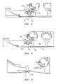
- a gas turbine engine rotor shown generally at 5 comprises a compressor section 10 and a downstream turbine section 15 in longitudinal serial flow relationship.
- Compressor section 10 includes a longitudinal stack of juxtaposed bladed compressor disks 20 disposed within a hub 25 comprising forward and aft portions 30 and 35, which compressively retain (clamp) the disks therebetween.
- Forward compressor hub portion 30, also known in the art as a forward stub shaft, is threaded at a forward end 40 thereof.
- a forward tie shaft 45 which is itself threaded at a forward end 50 thereof extends through compressor hub 25 engaging forward stub shaft 30 by threaded engagement of threaded forward end of forward tie shaft 45 with threaded forward end 40 of front stub shaft 30.
- Aft end of forward tie shaft 45 is provided with a radially outwardly extending flange 55 which abuts a mating flange 60 at the aft end of aft end portion 35 of compressor hub 25. Threaded engagement of the forward end of forward tie shaft 45 with threaded forward end 40 of front stub shaft 30 causes abutment of flanges 55 and 60 on forward tie shaft 45 and aft end portion 35 of hub 25 thereby compressively retaining the stack of bladed disks 20 between front stub shaft 30 and aft end portion 35 of hub 25 and compressively preloading disks 20 within hub 25.
- Turbine portion 15 of rotor 5 comprises a longitudinal stack of bladed turbine disks 65 juxtaposed with respect to one another between forward and aft ends of turbine hub 70.
- the forward portion of turbine hub 70 comprises a forward extension of a medial portion of the forwardmost turbine disk 65 and abuts the aft end of compressor hub 25 at 72.
- the aft end of turbine hub 70 comprises an aft extension of a medial portion of the aftmost bladed turbine disk 65.
- a forward end 80 of rear tie shaft 75 is threaded and engages a threaded aft end of aft end portion 35 of compressor hub 25.
- Aft end 85 of rear tie shaft 75 is threaded and receives a threaded aft nut 90 thereon.
- Nut 90 abuts the aft end of turbine hub 70 so that when threaded forward end 80 of aft tie shaft 75 is threaded into aft end portion 35 of compressor hub 25, the bladed turbine disks are compressively retained and preloaded within turbine hub 70 between the turbine hub and aft end portion 35 of compressor hub 25.
- the compressive preloaded retention of bladed compressor disks 20 between the forward and aft end portions of compressor hub 25 is achieved independently of the compressive preloaded retention of bladed turbine disks 65 and turbine hub 70, the preloading of compressor disks 20 within compressor hub 25 being determined by the extent to which the forward end of forward tie shaft 45 is threaded into the forward end portion of the compressor hub and the amount of preloading of bladed turbine disks 65 being determined by the extent of the threaded engagement of rear nut 90 on threaded end 85 of aft tie shaft 75.
- forward and rear tie shafts 45 and 75 react axial aerodynamic loading of the compressor and turbine bladed disks.
- the compressor and turbine portions of rotor 5 are rotationally coupled at a splined connection 95 of aft end portion 35 of compressor hub 25 and a forward end of turbine hub 70.
- aft end portion 35 of compressor hub 25 is provided with a radially inwardly extending flange 100 which abuts a mating radially outwardly extending flange 107 at the forward end of aft tie shaft 75 which abuts another mating radially inwardly extending flange 105 at the forwardmost end of turbine hub 70.
- the three mounting flanges 100, 107 and 105 are provided with mating holes which receive through-bolts 110 which connect the compressor and turbine hubs where the maximum difference in axial loading of the turbine and compressor occurs and for transmission of driving torque from the turbine hub to the compressor hub whereby the rotation of bladed turbine disks 65 in response to working fluid flowing through the turbine will rotationally drive the compressor bladed disks 20 for compression of air drawn into the engine, which, after compression, is exhausted to the engine's combustor (not shown).
- Tie shaft 75 then extends to the rear turbine disk hub similar to Fig 1 . with a reduced stack load requirement allowed by bolts 110.
- Bolts 110 reduce the amount of disk preloading required of the tie shafts for accommodation of axial loading of the turbine and compressor disks by working fluid flowing through the engine.
- aft end portion 35 of compressor hub 25 is provided with a radially inwardly extending flange 100 which abuts a mating radially inwardly extending flange 105 at the forwardmost end of turbine hub 70.
- the two mounting flanges 100 and 105 are provided with mating holes which receive through-bolts 110 which connect the compressor and turbine hubs where the maximum axial load delta occurs and for transmission of driving torque from the turbine hub to the compressor hub whereby the rotation of bladed turbine disks 65 in response to working fluid flowing through the turbine will rotationally drive the compressor bladed disks 20 for compression of air drawn into the engine, which, after compression, is exhausted to the engine's combustor (not shown).
- Tie shaft 75 is coupled to the aft turbine disk hub as in Fig 1 .
- Bolts 110 reduce the amount of disk preloading required of the tie shafts for accommodation of axial loading of the turbine and compressor disks by working fluid flowing through the engine.
- FIG. 4 an alternate arrangement for the engagement of the aft end of forward tie shaft 45 with the aft end portion 35 of compressor hub 25 is shown.
- aft end of forward tie shaft 45 is threaded at threaded aft end 115.
- a forward nut 120 is threaded onto threaded aft end 115 of forward tie shaft 45 and abuts radially inwardly extending flange 125 at the aft end of aft end portion 35 compressor hub 25.
- the dual tie shaft arrangement of the gas turbine engine rotor of the present invention defines independent axial load paths from the compressor and turbine disks through the forward and aft tie shafts which enables independent preloaded retention of the compressor bladed disks and the turbine bladed disks. Therefore, axial aerodynamic loading of the turbine blades which is opposite the axial aerodynamic loading of the compressor blades can be accommodated without excessive preloading of the compressor disks.
Landscapes
- Engineering & Computer Science (AREA)
- Mechanical Engineering (AREA)
- General Engineering & Computer Science (AREA)
- Turbine Rotor Nozzle Sealing (AREA)
- Structures Of Non-Positive Displacement Pumps (AREA)
Applications Claiming Priority (1)
| Application Number | Priority Date | Filing Date | Title |
|---|---|---|---|
| US12/916,010 US8794923B2 (en) | 2010-10-29 | 2010-10-29 | Gas turbine engine rotor tie shaft arrangement |
Publications (3)
| Publication Number | Publication Date |
|---|---|
| EP2447471A2 true EP2447471A2 (de) | 2012-05-02 |
| EP2447471A3 EP2447471A3 (de) | 2015-11-11 |
| EP2447471B1 EP2447471B1 (de) | 2019-11-27 |
Family
ID=44992596
Family Applications (1)
| Application Number | Title | Priority Date | Filing Date |
|---|---|---|---|
| EP11187330.3A Active EP2447471B1 (de) | 2010-10-29 | 2011-10-31 | Zugankeranordnung eines Rotors für ein Gasturbinentriebwerk |
Country Status (2)
| Country | Link |
|---|---|
| US (1) | US8794923B2 (de) |
| EP (1) | EP2447471B1 (de) |
Cited By (3)
| Publication number | Priority date | Publication date | Assignee | Title |
|---|---|---|---|---|
| WO2014037523A1 (de) * | 2012-09-07 | 2014-03-13 | Siemens Aktiengesellschaft | Verfahren zum zusammensetzen bzw. lösen eines eine anzahl von rotorbauteilen umfassenden rotors einer axial durchströmbaren turbomaschine und derartiger rotor |
| EP3708772A1 (de) * | 2019-03-14 | 2020-09-16 | United Technologies Corporation | Zugwellenanordnung für einen gasturbinenmotor |
| EP4682349A1 (de) * | 2024-07-15 | 2026-01-21 | Pratt & Whitney Canada Corp. | Zuganker für eine motorrotorbaugruppe |
Families Citing this family (14)
| Publication number | Priority date | Publication date | Assignee | Title |
|---|---|---|---|---|
| CA2760454C (en) * | 2010-12-03 | 2019-02-19 | Pratt & Whitney Canada Corp. | Gas turbine rotor containment |
| US8784062B2 (en) * | 2011-10-28 | 2014-07-22 | United Technologies Corporation | Asymmetrically slotted rotor for a gas turbine engine |
| US8875378B2 (en) * | 2011-11-07 | 2014-11-04 | United Technologies Corporation | Tie bolt employing differential thread |
| US9334794B2 (en) | 2013-06-05 | 2016-05-10 | Pratt & Whitney Canada Corp. | Rotary internal combustion engine with pilot subchamber and ignition element |
| US10048144B2 (en) | 2013-07-12 | 2018-08-14 | Pratt & Whitney Canada Corp. | Method and system for applying a compressive preload |
| US10393130B2 (en) | 2016-02-05 | 2019-08-27 | United Technologies Corporation | Systems and methods for reducing friction during gas turbine engine assembly |
| US10823013B2 (en) | 2016-09-30 | 2020-11-03 | General Electric Company | Dual tierod assembly for a gas turbine engine and method of assembly thereof |
| US10344596B2 (en) | 2017-05-02 | 2019-07-09 | Rolls-Royce Corporation | Gas turbine engine tie bolt arrangement |
| US10934844B2 (en) | 2018-05-31 | 2021-03-02 | Rolls-Royce Corporation | Gas turbine engine with fail-safe shaft scheme |
| GB2575046A (en) * | 2018-06-26 | 2020-01-01 | Rolls Royce Plc | Gas turbine engine spool |
| US12535035B2 (en) * | 2020-07-15 | 2026-01-27 | Rtx Corporation | Multi-ring spacer for gas turbine engine rotor stack assembly |
| DE102021126427A1 (de) | 2021-10-12 | 2023-04-13 | MTU Aero Engines AG | Rotoranordnung für eine Gasturbine mit an Rotorsegmenten ausgebildeten, geneigten axialen Kontaktflächen, Gasturbine und Fluggasturbine |
| US12264590B2 (en) | 2023-08-08 | 2025-04-01 | General Electric Company | Fan assembly for an engine having redundant trunnion retention |
| US20250305417A1 (en) * | 2024-03-27 | 2025-10-02 | General Electric Company | Gas turbine core tie rod with reduced span |
Family Cites Families (15)
| Publication number | Priority date | Publication date | Assignee | Title |
|---|---|---|---|---|
| US4965994A (en) | 1988-12-16 | 1990-10-30 | General Electric Company | Jet engine turbine support |
| US5267397A (en) | 1991-06-27 | 1993-12-07 | Allied-Signal Inc. | Gas turbine engine module assembly |
| US5537814A (en) | 1994-09-28 | 1996-07-23 | General Electric Company | High pressure gas generator rotor tie rod system for gas turbine engine |
| DE10358953A1 (de) * | 2003-12-15 | 2005-07-28 | Man Turbo Ag | Lagerung des Rotors einer Gasturbine |
| US7690889B2 (en) | 2005-07-20 | 2010-04-06 | United Technologies Corporation | Inner diameter variable vane actuation mechanism |
| US7588415B2 (en) | 2005-07-20 | 2009-09-15 | United Technologies Corporation | Synch ring variable vane synchronizing mechanism for inner diameter vane shroud |
| US7753647B2 (en) | 2005-07-20 | 2010-07-13 | United Technologies Corporation | Lightweight cast inner diameter vane shroud for variable stator vanes |
| US7665959B2 (en) | 2005-07-20 | 2010-02-23 | United Technologies Corporation | Rack and pinion variable vane synchronizing mechanism for inner diameter vane shroud |
| US7628579B2 (en) | 2005-07-20 | 2009-12-08 | United Technologies Corporation | Gear train variable vane synchronizing mechanism for inner diameter vane shroud |
| US7452188B2 (en) | 2005-09-26 | 2008-11-18 | Pratt & Whitney Canada Corp. | Pre-stretched tie-bolt for use in a gas turbine engine and method |
| DE102005052819A1 (de) * | 2005-11-05 | 2007-05-10 | Mtu Aero Engines Gmbh | Turbomaschine, insbesondere Gasturbine |
| US7750521B2 (en) | 2006-12-07 | 2010-07-06 | General Electric Company | Double-sided starter/generator for aircrafts |
| DE102007014667A1 (de) * | 2007-03-27 | 2008-10-02 | Siemens Ag | Gasturbine |
| DE102008015688A1 (de) * | 2008-03-26 | 2009-10-01 | Man Turbo Ag | Turbinenrotor für eine Gasturbine |
| US20110219781A1 (en) * | 2010-03-10 | 2011-09-15 | Daniel Benjamin | Gas turbine engine with tie shaft for axial high pressure compressor rotor |
-
2010
- 2010-10-29 US US12/916,010 patent/US8794923B2/en active Active
-
2011
- 2011-10-31 EP EP11187330.3A patent/EP2447471B1/de active Active
Non-Patent Citations (1)
| Title |
|---|
| None |
Cited By (7)
| Publication number | Priority date | Publication date | Assignee | Title |
|---|---|---|---|---|
| WO2014037523A1 (de) * | 2012-09-07 | 2014-03-13 | Siemens Aktiengesellschaft | Verfahren zum zusammensetzen bzw. lösen eines eine anzahl von rotorbauteilen umfassenden rotors einer axial durchströmbaren turbomaschine und derartiger rotor |
| CN104619954A (zh) * | 2012-09-07 | 2015-05-13 | 西门子公司 | 用于组装或拆卸可轴向穿流的涡轮机的包括一定数量的转子构件的转子的方法和这种转子 |
| EP2880264A1 (de) * | 2012-09-07 | 2015-06-10 | Siemens Aktiengesellschaft | Rotor für eine axial durchströmbare turbomaschine und doppelmutter zum verbinden zweier zugankerelemente |
| CN104619954B (zh) * | 2012-09-07 | 2016-08-24 | 西门子公司 | 用于组装或拆卸可轴向穿流的涡轮机的包括一定数量的转子构件的转子的方法和这种转子 |
| EP3708772A1 (de) * | 2019-03-14 | 2020-09-16 | United Technologies Corporation | Zugwellenanordnung für einen gasturbinenmotor |
| US11131195B2 (en) | 2019-03-14 | 2021-09-28 | Raytheon Technologies Corporation | Tie shaft assembly for a gas turbine engine |
| EP4682349A1 (de) * | 2024-07-15 | 2026-01-21 | Pratt & Whitney Canada Corp. | Zuganker für eine motorrotorbaugruppe |
Also Published As
| Publication number | Publication date |
|---|---|
| EP2447471B1 (de) | 2019-11-27 |
| EP2447471A3 (de) | 2015-11-11 |
| US8794923B2 (en) | 2014-08-05 |
| US20120107098A1 (en) | 2012-05-03 |
Similar Documents
| Publication | Publication Date | Title |
|---|---|---|
| US8794923B2 (en) | Gas turbine engine rotor tie shaft arrangement | |
| RU2608511C2 (ru) | Зубчатая система привода вентилятора для газотурбинного двигателя и газотурбинный двигатель, содержащий такую систему | |
| EP3361057B1 (de) | Turbine mit geringen überdrehzahlanforderungen und verfahren | |
| EP1908938A2 (de) | Gasturbinenwellenmontage | |
| CA2602322C (en) | Gas turbine engine assembly and method of assembling same | |
| US9624870B2 (en) | Adaptive fan system for a variable cycle turbofan engine | |
| CA2870683C (en) | Apparatus and method for assembling a damper bearing assembly | |
| US8459943B2 (en) | Gas turbine engine rotor sections held together by tie shaft, and with blade rim undercut | |
| US10024178B2 (en) | Chocking and retaining device | |
| EP2412940B1 (de) | Drehbare Komponentenfassung für einen Gasturbinenmotor | |
| EP3181945B1 (de) | Merkmale zur einer dämpfer- und dichtungsanordnung | |
| WO2014011269A2 (en) | Dynamic stability and mid axial preload control for a tie shaft coupled axial high pressure rotor | |
| EP3032070B1 (de) | Traglastverteilsystem | |
| US9422819B2 (en) | Rotor blade root spacer for arranging between a rotor disk and a root of a rotor blade | |
| US12264593B1 (en) | Damped bladed rotor for gas turbine engine | |
| EP3441562A1 (de) | Fan-scheibenvorrichtung | |
| US12515807B2 (en) | Bolted connection between mounting bracket and aircraft engine case(s) | |
| US12428986B2 (en) | Aircraft propulsion system engine with multiple independent rotating structures | |
| EP4628719A1 (de) | Drehzahlverhältnisstufe eines turbowellengetriebes | |
| CA3262409A1 (en) | Bolted connection between mounting bracket and aircraft engine case(s) | |
| EP2554791B1 (de) | Rotorkonstruktion einer Gasturbine |
Legal Events
| Date | Code | Title | Description |
|---|---|---|---|
| PUAI | Public reference made under article 153(3) epc to a published international application that has entered the european phase |
Free format text: ORIGINAL CODE: 0009012 |
|
| AK | Designated contracting states |
Kind code of ref document: A2 Designated state(s): AL AT BE BG CH CY CZ DE DK EE ES FI FR GB GR HR HU IE IS IT LI LT LU LV MC MK MT NL NO PL PT RO RS SE SI SK SM TR |
|
| AX | Request for extension of the european patent |
Extension state: BA ME |
|
| PUAL | Search report despatched |
Free format text: ORIGINAL CODE: 0009013 |
|
| AK | Designated contracting states |
Kind code of ref document: A3 Designated state(s): AL AT BE BG CH CY CZ DE DK EE ES FI FR GB GR HR HU IE IS IT LI LT LU LV MC MK MT NL NO PL PT RO RS SE SI SK SM TR |
|
| AX | Request for extension of the european patent |
Extension state: BA ME |
|
| RIC1 | Information provided on ipc code assigned before grant |
Ipc: F01D 5/02 20060101AFI20151008BHEP Ipc: F01D 5/06 20060101ALI20151008BHEP |
|
| 17P | Request for examination filed |
Effective date: 20160510 |
|
| RBV | Designated contracting states (corrected) |
Designated state(s): AL AT BE BG CH CY CZ DE DK EE ES FI FR GB GR HR HU IE IS IT LI LT LU LV MC MK MT NL NO PL PT RO RS SE SI SK SM TR |
|
| RAP1 | Party data changed (applicant data changed or rights of an application transferred) |
Owner name: UNITED TECHNOLOGIES CORPORATION |
|
| GRAP | Despatch of communication of intention to grant a patent |
Free format text: ORIGINAL CODE: EPIDOSNIGR1 |
|
| STAA | Information on the status of an ep patent application or granted ep patent |
Free format text: STATUS: GRANT OF PATENT IS INTENDED |
|
| INTG | Intention to grant announced |
Effective date: 20180713 |
|
| GRAJ | Information related to disapproval of communication of intention to grant by the applicant or resumption of examination proceedings by the epo deleted |
Free format text: ORIGINAL CODE: EPIDOSDIGR1 |
|
| STAA | Information on the status of an ep patent application or granted ep patent |
Free format text: STATUS: REQUEST FOR EXAMINATION WAS MADE |
|
| INTC | Intention to grant announced (deleted) | ||
| GRAP | Despatch of communication of intention to grant a patent |
Free format text: ORIGINAL CODE: EPIDOSNIGR1 |
|
| STAA | Information on the status of an ep patent application or granted ep patent |
Free format text: STATUS: GRANT OF PATENT IS INTENDED |
|
| INTG | Intention to grant announced |
Effective date: 20190604 |
|
| RIN1 | Information on inventor provided before grant (corrected) |
Inventor name: BENJAMIN, DANIEL Inventor name: TIRONE III, JOHN P. |
|
| GRAS | Grant fee paid |
Free format text: ORIGINAL CODE: EPIDOSNIGR3 |
|
| GRAA | (expected) grant |
Free format text: ORIGINAL CODE: 0009210 |
|
| STAA | Information on the status of an ep patent application or granted ep patent |
Free format text: STATUS: THE PATENT HAS BEEN GRANTED |
|
| AK | Designated contracting states |
Kind code of ref document: B1 Designated state(s): AL AT BE BG CH CY CZ DE DK EE ES FI FR GB GR HR HU IE IS IT LI LT LU LV MC MK MT NL NO PL PT RO RS SE SI SK SM TR |
|
| REG | Reference to a national code |
Ref country code: GB Ref legal event code: FG4D |
|
| REG | Reference to a national code |
Ref country code: CH Ref legal event code: EP |
|
| REG | Reference to a national code |
Ref country code: AT Ref legal event code: REF Ref document number: 1206857 Country of ref document: AT Kind code of ref document: T Effective date: 20191215 |
|
| REG | Reference to a national code |
Ref country code: DE Ref legal event code: R096 Ref document number: 602011063614 Country of ref document: DE |
|
| REG | Reference to a national code |
Ref country code: IE Ref legal event code: FG4D |
|
| REG | Reference to a national code |
Ref country code: NL Ref legal event code: MP Effective date: 20191127 |
|
| REG | Reference to a national code |
Ref country code: LT Ref legal event code: MG4D |
|
| PG25 | Lapsed in a contracting state [announced via postgrant information from national office to epo] |
Ref country code: ES Free format text: LAPSE BECAUSE OF FAILURE TO SUBMIT A TRANSLATION OF THE DESCRIPTION OR TO PAY THE FEE WITHIN THE PRESCRIBED TIME-LIMIT Effective date: 20191127 Ref country code: GR Free format text: LAPSE BECAUSE OF FAILURE TO SUBMIT A TRANSLATION OF THE DESCRIPTION OR TO PAY THE FEE WITHIN THE PRESCRIBED TIME-LIMIT Effective date: 20200228 Ref country code: LT Free format text: LAPSE BECAUSE OF FAILURE TO SUBMIT A TRANSLATION OF THE DESCRIPTION OR TO PAY THE FEE WITHIN THE PRESCRIBED TIME-LIMIT Effective date: 20191127 Ref country code: NO Free format text: LAPSE BECAUSE OF FAILURE TO SUBMIT A TRANSLATION OF THE DESCRIPTION OR TO PAY THE FEE WITHIN THE PRESCRIBED TIME-LIMIT Effective date: 20200227 Ref country code: SE Free format text: LAPSE BECAUSE OF FAILURE TO SUBMIT A TRANSLATION OF THE DESCRIPTION OR TO PAY THE FEE WITHIN THE PRESCRIBED TIME-LIMIT Effective date: 20191127 Ref country code: NL Free format text: LAPSE BECAUSE OF FAILURE TO SUBMIT A TRANSLATION OF THE DESCRIPTION OR TO PAY THE FEE WITHIN THE PRESCRIBED TIME-LIMIT Effective date: 20191127 Ref country code: LV Free format text: LAPSE BECAUSE OF FAILURE TO SUBMIT A TRANSLATION OF THE DESCRIPTION OR TO PAY THE FEE WITHIN THE PRESCRIBED TIME-LIMIT Effective date: 20191127 Ref country code: FI Free format text: LAPSE BECAUSE OF FAILURE TO SUBMIT A TRANSLATION OF THE DESCRIPTION OR TO PAY THE FEE WITHIN THE PRESCRIBED TIME-LIMIT Effective date: 20191127 Ref country code: BG Free format text: LAPSE BECAUSE OF FAILURE TO SUBMIT A TRANSLATION OF THE DESCRIPTION OR TO PAY THE FEE WITHIN THE PRESCRIBED TIME-LIMIT Effective date: 20200227 |
|
| PG25 | Lapsed in a contracting state [announced via postgrant information from national office to epo] |
Ref country code: RS Free format text: LAPSE BECAUSE OF FAILURE TO SUBMIT A TRANSLATION OF THE DESCRIPTION OR TO PAY THE FEE WITHIN THE PRESCRIBED TIME-LIMIT Effective date: 20191127 Ref country code: IS Free format text: LAPSE BECAUSE OF FAILURE TO SUBMIT A TRANSLATION OF THE DESCRIPTION OR TO PAY THE FEE WITHIN THE PRESCRIBED TIME-LIMIT Effective date: 20200327 Ref country code: HR Free format text: LAPSE BECAUSE OF FAILURE TO SUBMIT A TRANSLATION OF THE DESCRIPTION OR TO PAY THE FEE WITHIN THE PRESCRIBED TIME-LIMIT Effective date: 20191127 |
|
| PG25 | Lapsed in a contracting state [announced via postgrant information from national office to epo] |
Ref country code: AL Free format text: LAPSE BECAUSE OF FAILURE TO SUBMIT A TRANSLATION OF THE DESCRIPTION OR TO PAY THE FEE WITHIN THE PRESCRIBED TIME-LIMIT Effective date: 20191127 |
|
| PG25 | Lapsed in a contracting state [announced via postgrant information from national office to epo] |
Ref country code: PT Free format text: LAPSE BECAUSE OF FAILURE TO SUBMIT A TRANSLATION OF THE DESCRIPTION OR TO PAY THE FEE WITHIN THE PRESCRIBED TIME-LIMIT Effective date: 20200419 Ref country code: EE Free format text: LAPSE BECAUSE OF FAILURE TO SUBMIT A TRANSLATION OF THE DESCRIPTION OR TO PAY THE FEE WITHIN THE PRESCRIBED TIME-LIMIT Effective date: 20191127 Ref country code: DK Free format text: LAPSE BECAUSE OF FAILURE TO SUBMIT A TRANSLATION OF THE DESCRIPTION OR TO PAY THE FEE WITHIN THE PRESCRIBED TIME-LIMIT Effective date: 20191127 Ref country code: RO Free format text: LAPSE BECAUSE OF FAILURE TO SUBMIT A TRANSLATION OF THE DESCRIPTION OR TO PAY THE FEE WITHIN THE PRESCRIBED TIME-LIMIT Effective date: 20191127 Ref country code: CZ Free format text: LAPSE BECAUSE OF FAILURE TO SUBMIT A TRANSLATION OF THE DESCRIPTION OR TO PAY THE FEE WITHIN THE PRESCRIBED TIME-LIMIT Effective date: 20191127 |
|
| REG | Reference to a national code |
Ref country code: DE Ref legal event code: R097 Ref document number: 602011063614 Country of ref document: DE |
|
| PG25 | Lapsed in a contracting state [announced via postgrant information from national office to epo] |
Ref country code: SM Free format text: LAPSE BECAUSE OF FAILURE TO SUBMIT A TRANSLATION OF THE DESCRIPTION OR TO PAY THE FEE WITHIN THE PRESCRIBED TIME-LIMIT Effective date: 20191127 Ref country code: SK Free format text: LAPSE BECAUSE OF FAILURE TO SUBMIT A TRANSLATION OF THE DESCRIPTION OR TO PAY THE FEE WITHIN THE PRESCRIBED TIME-LIMIT Effective date: 20191127 |
|
| REG | Reference to a national code |
Ref country code: AT Ref legal event code: MK05 Ref document number: 1206857 Country of ref document: AT Kind code of ref document: T Effective date: 20191127 |
|
| PLBE | No opposition filed within time limit |
Free format text: ORIGINAL CODE: 0009261 |
|
| STAA | Information on the status of an ep patent application or granted ep patent |
Free format text: STATUS: NO OPPOSITION FILED WITHIN TIME LIMIT |
|
| 26N | No opposition filed |
Effective date: 20200828 |
|
| PG25 | Lapsed in a contracting state [announced via postgrant information from national office to epo] |
Ref country code: SI Free format text: LAPSE BECAUSE OF FAILURE TO SUBMIT A TRANSLATION OF THE DESCRIPTION OR TO PAY THE FEE WITHIN THE PRESCRIBED TIME-LIMIT Effective date: 20191127 Ref country code: PL Free format text: LAPSE BECAUSE OF FAILURE TO SUBMIT A TRANSLATION OF THE DESCRIPTION OR TO PAY THE FEE WITHIN THE PRESCRIBED TIME-LIMIT Effective date: 20191127 Ref country code: AT Free format text: LAPSE BECAUSE OF FAILURE TO SUBMIT A TRANSLATION OF THE DESCRIPTION OR TO PAY THE FEE WITHIN THE PRESCRIBED TIME-LIMIT Effective date: 20191127 |
|
| PG25 | Lapsed in a contracting state [announced via postgrant information from national office to epo] |
Ref country code: IT Free format text: LAPSE BECAUSE OF FAILURE TO SUBMIT A TRANSLATION OF THE DESCRIPTION OR TO PAY THE FEE WITHIN THE PRESCRIBED TIME-LIMIT Effective date: 20191127 |
|
| REG | Reference to a national code |
Ref country code: CH Ref legal event code: PL |
|
| PG25 | Lapsed in a contracting state [announced via postgrant information from national office to epo] |
Ref country code: LU Free format text: LAPSE BECAUSE OF NON-PAYMENT OF DUE FEES Effective date: 20201031 Ref country code: MC Free format text: LAPSE BECAUSE OF FAILURE TO SUBMIT A TRANSLATION OF THE DESCRIPTION OR TO PAY THE FEE WITHIN THE PRESCRIBED TIME-LIMIT Effective date: 20191127 |
|
| REG | Reference to a national code |
Ref country code: BE Ref legal event code: MM Effective date: 20201031 |
|
| PG25 | Lapsed in a contracting state [announced via postgrant information from national office to epo] |
Ref country code: LI Free format text: LAPSE BECAUSE OF NON-PAYMENT OF DUE FEES Effective date: 20201031 Ref country code: CH Free format text: LAPSE BECAUSE OF NON-PAYMENT OF DUE FEES Effective date: 20201031 Ref country code: BE Free format text: LAPSE BECAUSE OF NON-PAYMENT OF DUE FEES Effective date: 20201031 |
|
| PG25 | Lapsed in a contracting state [announced via postgrant information from national office to epo] |
Ref country code: IE Free format text: LAPSE BECAUSE OF NON-PAYMENT OF DUE FEES Effective date: 20201031 |
|
| PG25 | Lapsed in a contracting state [announced via postgrant information from national office to epo] |
Ref country code: TR Free format text: LAPSE BECAUSE OF FAILURE TO SUBMIT A TRANSLATION OF THE DESCRIPTION OR TO PAY THE FEE WITHIN THE PRESCRIBED TIME-LIMIT Effective date: 20191127 Ref country code: MT Free format text: LAPSE BECAUSE OF FAILURE TO SUBMIT A TRANSLATION OF THE DESCRIPTION OR TO PAY THE FEE WITHIN THE PRESCRIBED TIME-LIMIT Effective date: 20191127 Ref country code: CY Free format text: LAPSE BECAUSE OF FAILURE TO SUBMIT A TRANSLATION OF THE DESCRIPTION OR TO PAY THE FEE WITHIN THE PRESCRIBED TIME-LIMIT Effective date: 20191127 |
|
| PG25 | Lapsed in a contracting state [announced via postgrant information from national office to epo] |
Ref country code: MK Free format text: LAPSE BECAUSE OF FAILURE TO SUBMIT A TRANSLATION OF THE DESCRIPTION OR TO PAY THE FEE WITHIN THE PRESCRIBED TIME-LIMIT Effective date: 20191127 |
|
| REG | Reference to a national code |
Ref country code: DE Ref legal event code: R081 Ref document number: 602011063614 Country of ref document: DE Owner name: RAYTHEON TECHNOLOGIES CORPORATION (N.D.GES.D.S, US Free format text: FORMER OWNER: UNITED TECHNOLOGIES CORPORATION, FARMINGTON, CONN., US Ref country code: DE Ref legal event code: R081 Ref document number: 602011063614 Country of ref document: DE Owner name: RTX CORPORATION (N.D.GES.D. STAATES DELAWARE),, US Free format text: FORMER OWNER: UNITED TECHNOLOGIES CORPORATION, FARMINGTON, CONN., US |
|
| P01 | Opt-out of the competence of the unified patent court (upc) registered |
Effective date: 20230520 |
|
| PGFP | Annual fee paid to national office [announced via postgrant information from national office to epo] |
Ref country code: GB Payment date: 20250923 Year of fee payment: 15 |
|
| PGFP | Annual fee paid to national office [announced via postgrant information from national office to epo] |
Ref country code: FR Payment date: 20250924 Year of fee payment: 15 |
|
| REG | Reference to a national code |
Ref country code: DE Ref legal event code: R081 Ref document number: 602011063614 Country of ref document: DE Owner name: RTX CORPORATION (N.D.GES.D. STAATES DELAWARE),, US Free format text: FORMER OWNER: RAYTHEON TECHNOLOGIES CORPORATION (N.D.GES.D.STAATES DELAWARE), ARLINGTON, VA, US |
|
| PGFP | Annual fee paid to national office [announced via postgrant information from national office to epo] |
Ref country code: DE Payment date: 20250923 Year of fee payment: 15 |