EP2447509B1 - Brennersteuerungsverfahren und Brennersteuerung - Google Patents
Brennersteuerungsverfahren und Brennersteuerung Download PDFInfo
- Publication number
- EP2447509B1 EP2447509B1 EP11174978.4A EP11174978A EP2447509B1 EP 2447509 B1 EP2447509 B1 EP 2447509B1 EP 11174978 A EP11174978 A EP 11174978A EP 2447509 B1 EP2447509 B1 EP 2447509B1
- Authority
- EP
- European Patent Office
- Prior art keywords
- combustion
- combustor
- fuel flow
- fuel
- unit
- Prior art date
- Legal status (The legal status is an assumption and is not a legal conclusion. Google has not performed a legal analysis and makes no representation as to the accuracy of the status listed.)
- Active
Links
Images




Classifications
-
- F—MECHANICAL ENGINEERING; LIGHTING; HEATING; WEAPONS; BLASTING
- F02—COMBUSTION ENGINES; HOT-GAS OR COMBUSTION-PRODUCT ENGINE PLANTS
- F02C—GAS-TURBINE PLANTS; AIR INTAKES FOR JET-PROPULSION PLANTS; CONTROLLING FUEL SUPPLY IN AIR-BREATHING JET-PROPULSION PLANTS
- F02C9/00—Controlling gas-turbine plants; Controlling fuel supply in air- breathing jet-propulsion plants
- F02C9/26—Control of fuel supply
- F02C9/28—Regulating systems responsive to plant or ambient parameters, e.g. temperature, pressure, rotor speed
-
- F—MECHANICAL ENGINEERING; LIGHTING; HEATING; WEAPONS; BLASTING
- F02—COMBUSTION ENGINES; HOT-GAS OR COMBUSTION-PRODUCT ENGINE PLANTS
- F02C—GAS-TURBINE PLANTS; AIR INTAKES FOR JET-PROPULSION PLANTS; CONTROLLING FUEL SUPPLY IN AIR-BREATHING JET-PROPULSION PLANTS
- F02C3/00—Gas-turbine plants characterised by the use of combustion products as the working fluid
- F02C3/04—Gas-turbine plants characterised by the use of combustion products as the working fluid having a turbine driving a compressor
- F02C3/10—Gas-turbine plants characterised by the use of combustion products as the working fluid having a turbine driving a compressor with another turbine driving an output shaft but not driving the compressor
-
- F—MECHANICAL ENGINEERING; LIGHTING; HEATING; WEAPONS; BLASTING
- F02—COMBUSTION ENGINES; HOT-GAS OR COMBUSTION-PRODUCT ENGINE PLANTS
- F02C—GAS-TURBINE PLANTS; AIR INTAKES FOR JET-PROPULSION PLANTS; CONTROLLING FUEL SUPPLY IN AIR-BREATHING JET-PROPULSION PLANTS
- F02C9/00—Controlling gas-turbine plants; Controlling fuel supply in air- breathing jet-propulsion plants
- F02C9/16—Control of working fluid flow
- F02C9/20—Control of working fluid flow by throttling; by adjusting vanes
-
- F—MECHANICAL ENGINEERING; LIGHTING; HEATING; WEAPONS; BLASTING
- F02—COMBUSTION ENGINES; HOT-GAS OR COMBUSTION-PRODUCT ENGINE PLANTS
- F02C—GAS-TURBINE PLANTS; AIR INTAKES FOR JET-PROPULSION PLANTS; CONTROLLING FUEL SUPPLY IN AIR-BREATHING JET-PROPULSION PLANTS
- F02C9/00—Controlling gas-turbine plants; Controlling fuel supply in air- breathing jet-propulsion plants
- F02C9/26—Control of fuel supply
- F02C9/263—Control of fuel supply by means of fuel metering valves
-
- F—MECHANICAL ENGINEERING; LIGHTING; HEATING; WEAPONS; BLASTING
- F02—COMBUSTION ENGINES; HOT-GAS OR COMBUSTION-PRODUCT ENGINE PLANTS
- F02C—GAS-TURBINE PLANTS; AIR INTAKES FOR JET-PROPULSION PLANTS; CONTROLLING FUEL SUPPLY IN AIR-BREATHING JET-PROPULSION PLANTS
- F02C9/00—Controlling gas-turbine plants; Controlling fuel supply in air- breathing jet-propulsion plants
- F02C9/26—Control of fuel supply
- F02C9/32—Control of fuel supply characterised by throttling of fuel
- F02C9/34—Joint control of separate flows to main and auxiliary burners
-
- F—MECHANICAL ENGINEERING; LIGHTING; HEATING; WEAPONS; BLASTING
- F02—COMBUSTION ENGINES; HOT-GAS OR COMBUSTION-PRODUCT ENGINE PLANTS
- F02C—GAS-TURBINE PLANTS; AIR INTAKES FOR JET-PROPULSION PLANTS; CONTROLLING FUEL SUPPLY IN AIR-BREATHING JET-PROPULSION PLANTS
- F02C9/00—Controlling gas-turbine plants; Controlling fuel supply in air- breathing jet-propulsion plants
- F02C9/48—Control of fuel supply conjointly with another control of the plant
- F02C9/50—Control of fuel supply conjointly with another control of the plant with control of working fluid flow
- F02C9/54—Control of fuel supply conjointly with another control of the plant with control of working fluid flow by throttling the working fluid, by adjusting vanes
-
- F—MECHANICAL ENGINEERING; LIGHTING; HEATING; WEAPONS; BLASTING
- F05—INDEXING SCHEMES RELATING TO ENGINES OR PUMPS IN VARIOUS SUBCLASSES OF CLASSES F01-F04
- F05D—INDEXING SCHEME FOR ASPECTS RELATING TO NON-POSITIVE-DISPLACEMENT MACHINES OR ENGINES, GAS-TURBINES OR JET-PROPULSION PLANTS
- F05D2220/00—Application
- F05D2220/70—Application in combination with
- F05D2220/76—Application in combination with an electrical generator
-
- F—MECHANICAL ENGINEERING; LIGHTING; HEATING; WEAPONS; BLASTING
- F05—INDEXING SCHEMES RELATING TO ENGINES OR PUMPS IN VARIOUS SUBCLASSES OF CLASSES F01-F04
- F05D—INDEXING SCHEME FOR ASPECTS RELATING TO NON-POSITIVE-DISPLACEMENT MACHINES OR ENGINES, GAS-TURBINES OR JET-PROPULSION PLANTS
- F05D2240/00—Components
- F05D2240/35—Combustors or associated equipment
-
- F—MECHANICAL ENGINEERING; LIGHTING; HEATING; WEAPONS; BLASTING
- F05—INDEXING SCHEMES RELATING TO ENGINES OR PUMPS IN VARIOUS SUBCLASSES OF CLASSES F01-F04
- F05D—INDEXING SCHEME FOR ASPECTS RELATING TO NON-POSITIVE-DISPLACEMENT MACHINES OR ENGINES, GAS-TURBINES OR JET-PROPULSION PLANTS
- F05D2260/00—Function
- F05D2260/99—Ignition, e.g. ignition by warming up of fuel or oxidizer in a resonant acoustic cavity
-
- F—MECHANICAL ENGINEERING; LIGHTING; HEATING; WEAPONS; BLASTING
- F05—INDEXING SCHEMES RELATING TO ENGINES OR PUMPS IN VARIOUS SUBCLASSES OF CLASSES F01-F04
- F05D—INDEXING SCHEME FOR ASPECTS RELATING TO NON-POSITIVE-DISPLACEMENT MACHINES OR ENGINES, GAS-TURBINES OR JET-PROPULSION PLANTS
- F05D2270/00—Control
- F05D2270/30—Control parameters, e.g. input parameters
- F05D2270/304—Spool rotational speed
-
- F—MECHANICAL ENGINEERING; LIGHTING; HEATING; WEAPONS; BLASTING
- F05—INDEXING SCHEMES RELATING TO ENGINES OR PUMPS IN VARIOUS SUBCLASSES OF CLASSES F01-F04
- F05D—INDEXING SCHEME FOR ASPECTS RELATING TO NON-POSITIVE-DISPLACEMENT MACHINES OR ENGINES, GAS-TURBINES OR JET-PROPULSION PLANTS
- F05D2270/00—Control
- F05D2270/30—Control parameters, e.g. input parameters
- F05D2270/313—Air temperature
Definitions
- the invention particular relates to a combustor control method and a combustor controller suitable for the combustion control of dry low-NOx combustors for multi-shafts gas turbine that is equipped with a premixed combustion unit.
- Another known combustor is designed to carry out the transferring to the premixed combustion for the purpose of achieving the stable combustion and the NOx emission reduction based on fuel flow demand in a systematic manner (see JP-2001-263095-A , for example).
- EP 2 143 908 A2 describes a twin-shaft gas turbine, which has a gas generator including a compressor, a combustor, and a high-pressure turbine, is configured to make a first control mode and a second control mode selectively useable for control of the gas generator.
- a first control mode an IGV angle in the compressor is controlled in accordance with a corrected shaft rotation speed of the gas generator
- the IGV angle is controlled to maintain a constant gas generator shaft rotation speed.
- the present invention makes it possible to calculate the combustion air flow and the fuel flow in multi-shafts gas turbine with high precision and without the need of performing complicated calculations and thereby calculate a fuel-air ratio necessary for stable combustion control.
- Fig. 1 is a block diagram showing the configuration of the gas turbine system employing the combustor controller in accordance with the embodiment of the present invention.
- the gas turbine system comprises a gas turbine 100 and a combustor controller 200.
- the gas turbine 100 includes a gas generator turbine 110 and a power turbine 120.
- the gas generator turbine 110 operating perfectly independently of the outside, includes a compressor 112, combustors 114 and high pressure turbine 116.
- the compressor 112 and the high pressure turbine 116 are connected by a first shaft AX1.
- the inlet of the compressor 112 is equipped with inlet guide vanes 112A.
- the combustors 114 are made up of a plurality of combustion units. The details of the combustors 114 will be explained later referring to Fig. 2 .
- the power turbine 120 has a shaft that is mechanically separated from that of the gas generator turbine 110.
- the power turbine 120 includes low pressure turbine 122.
- the low pressure turbine 122 is connected to a second shaft AX2.
- the second shaft AX2 is separate from the aforementioned first shaft AX1 of the gas generator turbine 110.
- the second turbine 122 transmits torque to an external device such as a power generator.
- Combustion air is introduced from outside to the compressor 112, compressed by the compressor 112 and then supplied to the combustors 114.
- combustion gas is generated (combustion is carried out) using the combustion air and fuel gas supplied from a fuel system.
- the combustion gas after the combustion is lead to the high pressure turbine 116 of the gas generator turbine 110 for heat recovery.
- combustion air flow and power necessary for the compressor 112 are uniquely determined by the gas turbine load, according to the correlation between the revolution speed of the turbine 116 and the open position of the inlet guide vanes 112A.
- the revolution speed of the turbine 116 is a speed at which the power necessary for the compressor 112 balances with torque generated by the heat recovery by the turbine 116 of the gas generator turbine 110.
- the combustion gas after the heat recovery by the gas generator turbine 110 undergoes the next heat recovery by the power turbine 120 and thereby transmits torque to the external device such as the power generator.
- the fuel flow i.e., the amount of the flow of the fuel
- the fuel flow is changed and controlled in order to increase/decrease the torque generated by the power turbine 120, that is, the gas turbine load.
- the gas generator turbine 110 is equipped with a temperature detector TE for detecting the atmospheric temperature at the inlet of the compressor 112, an open position detector XE2 for detecting the open position of the inlet guide vanes 112A, and a revolution speed detector XE1 for detecting the revolution speed of the gas generator turbine 110.
- the power turbine 120 is equipped with a revolution speed detector XE3 for detecting the revolution speed of the power turbine 120.
- a fuel supply system of the combustors 114 is equipped with a heat value detector XE4 for detecting the heat value of the fuel gas supplied to the combustors 114.
- the combustor controller 200 includes a fuel flow demand unit 210, an ignition/extinction control unit 220 and functional unit of fuel flow demand for each of combustion units 230.
- the fuel flow demand unit 210 outputs a fuel flow demand, FFD, according to the revolution speed of the gas generator turbine 110 detected by the revolution speed detector XE1 and the revolution speed of the power turbine 120 detected by the revolution speed detector XE3.
- the fuel flow demand unit 210 outputs the fuel flow demand, FFD, according to the revolution speeds of the gas generator turbine 110 and the power turbine 120 so that the output of the power generator gradually increases with time from the startup of the turbines 110 and 120 until the turbines reach their rated states.
- the ignition/extinction control unit 220 outputs an ignition operation command and an extinction operation command (for controlling the ignition and extinction of the combustion units constituting the combustors 114) to the functional unit of fuel flow demand for each of combustion units 230 based on the inlet temperature of the compressor 112 detected by the temperature detector TE, the open position of the inlet guide vanes 112A detected by the open position detector XE2, the revolution speed of the gas generator turbine 110 detected by the revolution speed detector XE1, the heat value of the fuel gas supplied to the combustors 114 detected by the heat value detector XE4 and the fuel flow demand, FFD, outputted by the fuel flow demand unit 210.
- the ignition/extinction control unit 220 outputs flame control reference, FCR, to the functional unit of fuel flow demand for each of combustion units unit 230 based on the open position of the inlet guide vanes 112A detected by the open position detector XE2, the revolution speed of the gas generator turbine 110 detected by the revolution speed detector XE1 and the fuel flow demand, FFD, outputted by the fuel flow demand unit 210.
- FCR flame control reference
- the functional unit of fuel flow demand for each of combustion units 230 calculates fuel flow demand, FFD, (for controlling the flows of the fuel gas supplied to the combustion units of the combustors 114) based on the inlet temperature of the compressor 112 detected by the temperature detector TE, the fuel flow demand, FFD, outputted by the fuel flow demand unit 210 and the flame control reference, FCR, outputted by the ignition/extinction control unit 220.
- the functional unit of fuel flow demand for each of combustion units 230 outputs the calculated fuel flow demand, FFD, to the combustors 114. The details of the functional unit of fuel flow demand for each of combustion units 230 will be explained later referring to Fig. 4 .
- Fig. 2 is a block diagram showing the configuration of the combustors employed for the gas turbine system in accordance with the embodiment of the present invention.
- Fig. 2 shows the positional relationship among combustion fields of a dry low-NOx combustors and the configuration of a fuel gas system and a combustion air system for supplying the fuel gas and the combustion air to the combustion fields.
- the combustors 114 includes a diffusive combustion unit F1 placed at the center in a combustor and four premixed combustion units F21, F22, F23 and F24 arranged around the diffusive combustion unit F1 at even intervals.
- the combustors 114 is of the type realizing the NO x reduction by changing the number of used combustion units across a wide range of the fuel-air ratio from the startup of the gas turbine until the gas turbine load reaches the rated load.
- the diffusive combustion unit F1 having a wide operating range regarding available fuel-air ratios, is set at the central position of the combustor and carries out solo combustion at startup.
- the number of used premixed combustion units is successively increased at each stage at which an appropriate fuel-air ratio permissible for each premixed combustion units F21, F22, F23, F24 can be secured, by which stable NO x reduction is realized across a wide range of the gas turbine load.
- the combustion gas is generated (combustion) using the diffusive combustion units F1 only.
- the premixed combustion units F21 is added and the combustion gas is generated (combustion) using the diffusive combustion units F1 and the premixed combustion units F21.
- the premixed combustion units F22 is added and the combustion gas is generated (combustion) using the diffusive combustion units F1, the premixed combustion units F21 and the premixed combustion units F22.
- the number of used premixed combustion units is successively increased in this way.
- the combustion gas is generated (combustion) using the diffusive combustion units F1 and all the four premixed combustion units F21, ⁇ ⁇ , F24.
- the number of premixed combustion units is not restricted to four.
- a main pipe for feeding the fuel gas is equipped with a fuel gas shut-off valve, SRV.
- the main pipe is connected to auxiliary pipes supplying the fuel gas independently to the diffusive combustion units F1 and the four premixed combustion units F21, F22, F23 and F24, respectively.
- the auxiliary pipes are equipped with fuel gas flow control valves FlGCV, F21GCV, F22GCV, F23GCV and F24GCV, respectively.
- the open positions of the fuel gas flow control valves FlGCV, F21GCV, F22GCV, F23GCV and F24GCV are controlled by the functional unit of fuel flow demand for each of combustion units 230.
- the flows of the fuel gas supplied to the combustion units are calculated from the fuel flow demand, FFD, used for controlling the open positions of the fuel gas flow control valves FlGCV, F21GCV, ... , F24GCV in consideration of the properties of the flows being proportional to the open positions of the fuel gas flow control valves FlGCV, F21GCV, ... , F24GCV, by controlling the front pressure of the fuel gas flow control valves FlGCV, F21GCV, ... , F24GCV with the fuel gas shut-off valve, SRV, and using the fuel gas flow control valves FlGCV, F21GCV, ⁇ ⁇ , F24GCV in the critical conditions.
- the ignition and extinction of the diffusive combustion units F1 and the four premixed combustion units F21, F22, F23 and F24 are operated based on an ignition/extinction command issued from the ignition/extinction control unit 220.
- the multi-shaft gas turbines have the characteristic that the combustion air flow and the fuel flow change continuously accompanying the change in the gas turbine load since the gas generator turbine (in which the combustors is installed) and the power turbine (for supplying the torque to outside) are independent of each other in the multi-shaft gas turbines as mentioned above. Therefore, it is difficult to employ the conventional method that controls the fuel-air ratio by estimating the combustion temperature from the gas turbine's state quantities or controls the fuel-air ratio using a function (equation) of the fuel flow only.
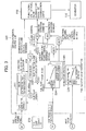
- Fig. 3 is a block diagram showing the configuration of the ignition/extinction control unit constituting the combustor controller in accordance with the embodiment of the present invention.
- the ignition/extinction control unit 220 includes a revolution speed correction unit 221, flame control reference, FCR, -oriented combustion air flow calculation unit 222, flame control reference, FCR, -oriented fuel flow calculation unit 223, a combustion transferring setting unit 224, a fuel gas heat value correction unit 225, a limitation unit LIM, a ratio calculation unit RTO, multiplication units MLT1 and MLT2, and judgment units JD1 and JD2.
- the revolution speed correction unit 221 corrects the revolution speed of the gas generator turbine 110 detected by the revolution speed detector XE1 using the inlet temperature (°C) of the compressor 112 detected by the temperature detector TE and thereby figures out a corrected revolution speed of the gas generator turbine 110. Specifically, the revolution speed correction unit 221 calculates a temperature-corrected revolution speed as ((revolution speed of the gas generator turbine 110 detected by the revolution speed detector XE1) ⁇ (288.15/(inlet temperature of the compressor 112 detected by the temperature detector TE (°C) + 273.15))).
- the flame control reference, FCR, -oriented combustion air flow calculation unit 222 calculates flame control reference, FCR, -oriented combustion air flow (combustion air flow for the flame control reference, FCR) based on the revolution speed of the gas generator turbine 110 corrected by the revolution speed correction unit 221 and the revolution speed of the power turbine 120 detected by the revolution speed detector XE3.
- the limitation unit LIM compares the flame control reference, FCR, -oriented combustion air flow calculated by the flame control reference, FCR, -oriented combustion air flow calculation unit 222 with preset minimum and maximum values of the flame control reference, FCR, -oriented combustion air flow and thereby limits the flame control reference, FCR, -oriented combustion air flow within the range between the minimum and maximum values.
- the flame control reference, FCR,-oriented fuel flow calculation unit 223 calculates and outputs a fuel flow corresponding to the fuel flow demand, FFD, outputted by the fuel flow demand unit 210.
- the fuel flow demand, FFD, outputted by the fuel flow demand unit 210 is a demand value determined based on the revolution speed of the gas generator turbine 110 detected by the revolution speed detector XE1 and the revolution speed of the power turbine 120 detected by the revolution speed detector XE3 as mentioned above.
- the ratio calculation unit RTO calculates the fuel-air ratio ((fuel flow demand, FFD, value)/(flame control reference, FCR, -oriented combustion air flow)) by use of the flame control reference, FCR, -oriented combustion air flow calculated by the flame control reference, FCR, - oriented combustion air flow calculation unit 222 and the fuel flow demand, FFD, value (i.e., the flame control reference, FCR, -oriented fuel flow) calculated by the flame control reference, FCR, -oriented fuel flow calculation unit 223.
- the ratio calculation unit RTO outputs the calculated fuel-air ratio as the flame control reference, FCR.
- the combustion transferring setting unit 224 outputs a corrected setting value of the flame control reference, FCR, according to the inlet temperature (°C) of the compressor 112 detected by the temperature detector TE.
- the combustion transferring setting unit 224 is equipped with maps representing properties of the flame control reference, FCR, setting value decreasing with the increase in the compressor inlet temperature.
- the combustion transferring setting unit 224 outputs the flame control reference, FCR, setting value corrected based on the compressor inlet temperature (°C) detected by the temperature detector TE and the map.
- the ignition transferring includes the following four cases: 1) judgment on the ignition of the premixed combustion units F21 when the diffusive combustion units F1 is currently in use, 2) judgment on the ignition of the premixed combustion units F22 when the diffusive combustion units F1 and the premixed combustion units F21 are currently in use, 3) judgment on the ignition of the premixed combustion units F23 when the diffusive combustion units F1 and the premixed combustion units F21 and F22 are currently in use, and 4) judgment on the ignition of the premixed combustion units F24 when the diffusive combustion units F1 and the premixed combustion units F21, F22 and F23 are currently in use.
- the extinction transferring also includes four cases similarly. Therefore, the combustion transferring setting unit 224 has eight maps.
- the fuel gas heat value correction unit 225 outputs a correction coefficient which changes depending on the heat value of the fuel gas supplied to the combustors 114 detected by the heat value detector XE4.
- the correction coefficient equals 1.0 at a prescribed temperature and increases/decreases linearly as the temperature decreases/increases from the prescribed temperature.
- the multiplication unit MLT1 multiplies one of the corrected setting values of the flame control reference, FCR, outputted by the combustion transferring setting unit 224 by the correction coefficient determined by the fuel gas heat value correction unit 225 and thereby outputs a setting value of an ignition transferring point flame control reference.
- the multiplication unit MLT2 multiplies the other of the corrected setting values of the flame control reference, FCR, outputted by the combustion transferring setting unit 224 by the correction coefficient determined by the fuel gas heat value correction unit 225 and thereby outputs a setting value of an extinction transferring point flame control reference, FCR.
- the judgment unit JD1 outputs an ignition operation command to the functional unit of fuel flow demand for each of combustion units 230 (to the combustors 114) when the flame control reference, FCR, outputted by the ratio calculation unit RTO exceeds the setting value of the ignition transferring point flame control reference, FCR, outputted by the multiplication unit MLT1. This causes the combustors 114 to ignite a specified combustion unit.
- the judgment unit JD2 outputs an extinction operation command to the functional unit of fuel flow demand for each of combustion units 230 (to the combustors 114) when the flame control reference, FCR, outputted by the ratio calculation unit RTO falls below the setting value of the extinction transferring point flame control reference, FCR, outputted by the multiplication unit MLT2. This causes the combustors 114 to extinguish a specified combustion unit.
- the combustion air flow is calculated in consideration of the compressor intake air flow (changing dependently on the revolution speed of the compressor, intake air temperature and the open position of the compressor inlet guide vanes), the air flow used for cooling the turbine, the air flow leaking out of the system, etc.
- the combustion air flow can be calculated precisely and immediately, corresponding to the change of the actual combustion air flow, and without the need of performing complicated calculations.
- the fuel gas flows are calculated from the fuel flow demand, FFD, used for controlling the open positions of the fuel gas flow control valves (GCVs) in consideration of the properties of the flows being proportional to the open positions of the fuel gas flow control valves, by controlling the front pressure of the fuel gas flow control valves with the fuel gas shut-off valve (SRV) and using the fuel gas flow control valves in the critical conditions.
- FFD fuel flow demand
- the fuel flows can be calculated precisely and immediately, corresponding to the change of the actual fuel flows, and without the need of performing complicated calculations.
- the ignition operation command and the extinction operation command regarding the combustion transferring can be outputted by calculating the flame control reference, FCR, (fuel-air ratio) necessary for stable combustion control and comparing the calculated flame control reference, FCR, with FCR settings specified by an ignition point FCR function and an extinction point FCR function for the combustion transferring at the atmospheric temperature.
- FCR flame control reference
- the ignition point FCR function and the extinction point FCR function can be corrected based on the properties of the fuel used for the combustion. This enables control that further stabilizes the combustion.
- Fig. 4 is a block diagram showing the configuration of the combustion unit fuel flow demand unit constituting the combustor controller in accordance with the embodiment of the present invention.
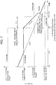
- Figs. 5 - 7 are graphs for explaining the operation of the combustion unit fuel flow demand unit constituting the combustor controller in accordance with the embodiment of the present invention.
- the functional unit of fuel flow demand for each of combustion units 230 includes a local minimum/maximum setting unit 231, a median selector MED_SEL, a rate limiter RL, an FCR change rate limitation unit 232, a combustion transferring repeat prevention timer 233, a transferring F2 ratio generating unit 234, a transferring F2 ratio correction bias generating unit 235, an F24 ratio generating unit 236A, an F23 ratio generating unit 236B, an F22 ratio generating unit 236C, and multiplication units MLT0, NLTA, MLTB and MLTC.
- the local minimum/maximum setting unit 231 outputs a local minimum value FCRRLMN and a local maximum value FCRRLMX as limiting values for the flame control reference FCR outputted by the ignition/extinction control unit 220.
- the median selector MED_SEL compares the flame control reference FCR outputted by the ignition/extinction control unit 220 with the local minimum value, FCRRLMN, and the local maximum value, FCRRLMX, outputted by the local minimum/maximum setting unit 231 and outputs the median of the flame control reference FCR, the local minimum value, FCRRLMN, and the local maximum value, FCRRLMX.
- the horizontal axis represents time and the vertical axis represents a change rate-limited flame control reference FCRRL outputted by the rate limiter RL which will be explained later.
- the local minimum value FCRRLMN outputted by the local minimum/maximum setting unit 231 remains at a constant level indicated with the chain line.
- the local minimum value FCRRLMN has been set at the (n-1)-th stage ignition point.
- the local maximum value FCRRLMX remains at a constant level indicated with the dotted line.
- the local maximum value FCRRLMX has been set at the n-th stage extinction point.
- the (n-1)-th stage ignition point means the ignition point for the diffusive combustion units F1 and the n-th stage extinction point means the extinction point for the premixed combustion units F21.
- the flame control reference FCR outputted by the ignition/extinction control unit 220 is assumed to monotonically increase as indicated with the solid line. Since the flame control reference FCR is between the local minimum value FCRRLMN and the local maximum value FCRRLMX at the time t0, the median selector MED_SEL outputs the flame control reference FCR directly as the change rate-limited flame control reference FCRRL as indicated with the thick solid line.
- the median selector MED_SEL After time t1, as the flame control reference FCR exceeds the local maximum value FCRRLMX, the median selector MED_SEL outputs the value limited by the local maximum value FCRRLMX as the change rate-limited flame control reference FCRRL as indicated with the thick solid line.
- the rate limiter RL is used for outputting the change rate-limited flame control reference FCRRL indicated between the time t2 and time t4 in Fig. 5 in response to the flame control reference, FCR, outputted by the median selector MED_SEL.
- the rate limiter RL limits the change rate of the flame control reference so as to make it constant.
- the FCRRL change rate limitation unit 232 limits the operation of the rate limiter RL between the time t2 and time t3 in Fig. 5 within a time period T1.
- the combustion transferring repeat prevention timer 233 delays the operating period T1 of the rate limiter RL between the time t3 and the time t4 in Fig. 5 by a time period T2.
- the local minimum value FCRRLMN outputted by the local minimum/maximum setting unit 231 is changed stepwise from the previous (n-1)-th stage ignition point to the n-th stage ignition point as indicated with the chain line.
- the local maximum value FCRRLMX is changed stepwise from the previous n-th stage extinction point to the (n+1)-th stage extinction point as indicated with the dotted line.
- the change rate-limited flame control reference FCRRL changes stepwise at the time t2 from the local maximum value FCRRLMX used before the time t2 (n-th stage extinction point) to the value of the flame control reference FCR indicated with the solid line, which is undesirable.
- the rate limiter RL limits the increase of the change rate-limited flame control reference FCRRL during the period T1 from the time t2 (due to the operation of the FCRRL change rate limitation unit 232) so that the change rate-limited flame control reference FCRRL increases not stepwise but at a constant change rate from the local maximum value FCRRLMX used before the time t2 (n-th stage extinction point). Also after the expiration of the period T1 at the time t3, the rate limiter RL limits the increase of the change rate-limited flame control reference FCRRL during the period T2 from the time t3 (due to the operation of the combustion transferring repeat prevention timer 233) so that the change rate-limited flame control reference FCRRL increases at a constant change rate.
- This limitation is carried out for preventing a repeat of the combustion transferring, such as ignition of the premixed combustion unit F21 followed by its extinction and further ignition caused by external disturbance, etc.
- the flame control reference FCR is directly outputted as the change rate-limited flame control reference FCRRL by the original operation of the median selector MED_SEL when the flame control reference FCR is between the local minimum value FCRRLMN and the local maximum value FCRRLMX.
- the flame control reference FCR after the flame control reference FCR has reached the n-th stage ignition point, the flame control reference (FCRRL) is increased, with the limitation on the change rate, from the n-th extinction point to the n-th ignition point at a constant rate, by which the ignition can be conducted smoothly through the transferring band, without retardation of the ignition operation due to external disturbance.
- the transferring F2 ratio generating unit 234 changes an F2 ratio according to the change rate-limited flame control reference FCRRL.
- the F2 ratio is a value calculated as (the sum of the fuel flow demand, FFD, values for the four premixed combustion units F21, F22, F23 and F24)/((the fuel flow demand, FFD, value for the diffusive combustion units F1) + (the sum of the fuel flow demand, FFD, values for the four premixed combustion units F21, F22, F23 and F24)).
- the transferring F2 ratio generating unit 234 sets the F2 ratio at 0.
- the transferring F2 ratio generating unit 234 sets the F2 ratio at Y1 (e.g., 0.5).
- the change rate-limited flame control reference FCRRL increases from X1, the F2 ratio is decreased from Y1.
- the transferring F2 ratio generating unit 234 sets the F2 ratio at Y2 (e.g., 0.6).
- the F2 ratio is decreased from Y2.
- the transferring F2 ratio generating unit 234 sets the F2 ratio at Y3 (e.g., 0.7).
- the F2 ratio is decreased from Y3.
- the horizontal axis represents the change rate-limited flame control reference FCRRL and the vertical axis represents the flow of the fuel gas supplied to the whole combustors.
- the F2 ratio When the change rate-limited flame control reference FCRRL is less than X1, the F2 ratio equals 0, and thus the fuel gas is supplied to the diffusive combustion units F1 only. The flow of the supplied fuel gas increases with the increase in the change rate-limited flame control reference FCRRL.
- the F2 ratio is set at Y1 (e.g., 0.5), and thus the fuel gas is supplied also to the premixed combustion unit F21.
- the fuel gas flow supplied to the premixed combustion units F21 is controlled by controlling the front pressure of the fuel gas flow control valve F1GCV with the fuel gas shut-off valve SRV and using the fuel gas flow control valve F1GCV in the vicinity of the critical condition.
- the change rate-limited flame control reference FCRRL increases from X1
- the fuel gas flow supplied to the diffusive combustion unit F1 is increased while keeping the fuel gas flow supplied to the premixed combustion units F21 substantially at a constant level (i.e., the F2 ratio decreases from Y1).
- the F2 ratio is set at Y2 (e.g., 0.6), and thus the fuel gas is supplied also to the premixed combustion units F22.
- Equal amounts of fuel gas are supplied to the premixed combustion units F21 and F22.
- the transferring F2 ratio correction bias generating unit 235 shown in Fig. 4 generates a correction bias according to the inlet temperature of the compressor 112 detected by the temperature detector TE.
- the correction bias equals 0.0 when the inlet temperature of the compressor 112 is at a prescribed temperature and increases/decreases from 0.0 according to the extent of the decrease/increase of the compressor inlet temperature from the prescribed temperature.
- An adder AD adds the correction bias outputted by the transferring F2 ratio correction bias generating unit 235 to the F2 ratio outputted by the transferring F2 ratio generating unit 234 and thereby outputs a corrected F2 ratio.
- the transferring F2 ratio correction bias generating unit 235 is equipped with a certain number of maps corresponding to the number of turning points of the graph (function) representing the relationship between the change rate-limited flame control reference FCRRL and the F2 ratio.
- the F2 ratio changes from 0 to Y1 when the change rate-limited flame control reference FCRRL reaches X1. This is the first turning point.
- the graph of the F2 ratio changes its direction to decrease from Y1 when the change rate-limited flame control reference FCRRL increases from X1. This is the second turning point.
- the transferring F2 ratio correction bias generating unit 235 has a certain number of maps corresponding to the number of such turning points.
- the multiplication unit MLT0 multiplies the fuel flow demand outputted by the fuel flow demand unit 210 by the corrected F2 ratio outputted by the adder AD and thereby outputs the F2 ratio-multiplied fuel flow demand.
- the F24 ratio generating unit 236A determines the ratio of the fuel gas flow to be supplied to the premixed combustion unit F24 within the F2 ratio based on the change rate-limited flame control reference FCRRL outputted by the rate limiter RL and outputs the determined ratio. For example, when the change rate-limited flame control reference FCRRL reaches X4, the F24 ratio generating unit 236A outputs 0.25 as shown in Fig. 4 .
- the multiplication unit MLTA multiplies the output Z4 of the multiplication unit MLT0 by the F24 ratio outputted by the F24 ratio generating unit 236A and thereby outputs an F24 fuel flow demand.
- the F24 fuel flow demand is outputted to the fuel gas flow control valve F24GCV shown in Fig. 2 .
- the F23 ratio generating unit 236B determines the ratio of the fuel gas flow to be supplied to the premixed combustion unit F23 within the F2 ratio based on the change rate-limited flame control reference FCRRL outputted by the rate limiter RL and outputs the determined ratio. For example, when the change rate-limited flame control reference FCRRL reaches X3, the F23 ratio generating unit 236B outputs 0.33 as shown in Fig. 4 .
- a subtractor DFB subtracts the F24 fuel flow demand outputted by the multiplication unit MLTA ((A) in Fig. 4 ) from the output Z4 of the multiplication unit MLT0.
- the multiplication unit MLTB multiplies the output D3 of the subtractor DFB by the F23 ratio outputted by the F23 ratio generating unit 236B and thereby outputs an F23 fuel flow demand.
- the F23 fuel control demand is outputted to the fuel gas flow control valve F23GCV shown in Fig. 2 .
- the F22 ratio generating unit 236C determines the ratio of the fuel gas flow to be supplied to the premixed combustion unit F22 within the F2 ratio based on the change rate-limited flame control reference FCRRL outputted by the rate limiter RL and outputs the determined ratio. For example, when the change rate-limited flame control reference FCRRL reaches X2, the F22 ratio generating unit 236C outputs 0.5 as shown in Fig. 4 .
- a subtractor DFC subtracts the F23 fuel demand outputted by the multiplication unit MLTB ((B) in Fig. 4 ) from the output Z3 of the subtractor DFB.
- the multiplication unit MLTC multiplies the output D2 of the subtractor DFC by the F22 ratio outputted by the F22 ratio generating unit 236C and thereby outputs an F22 fuel flow demand.
- the F22 fuel flow demand is outputted to the fuel gas flow control valve F22GCV shown in Fig. 2 .
- a subtractor DFD subtracts the F22 fuel flow demand outputted by the multiplication unit MLTC ((C) in Fig. 4 ) from the output Z2 of the subtractor DFC and thereby outputs an F21 fuel flow demand (Z1).
- the F21 fuel flow demand is outputted to the fuel gas flow control valve F21GCV shown in Fig. 2 .
- the change rate-limited flame control reference FCRRL is less than X1
- the F2 ratio outputted by the transferring F2 ratio generating unit 234 equals 0, and thus the output Z4 of the multiplication unit MLT0 equals 0.
- the correction bias outputted by the transferring F2 ratio correction bias generating unit 235 is assumed to be 0 in this explanation. Therefore, the fuel flow demand for the premixed combustion units F21, F22, F23 and F24 are all 0.
- the whole of the fuel flow demand outputted by the fuel flow demand unit 210 is inputted to the subtractor DF1.
- the subtractor DF1 subtracts the sum of the F21 fuel flow demand ((D) in Fig. 4 ), the F22 fuel flow demand ((C) in Fig.
- the F23 fuel flow demand ((B) in Fig. 4 ) and the F24 fuel flow demand ((A) in Fig. 4 ) from the fuel flow demand outputted by the fuel flow demand unit 210. Since A + B + C + D 0 in this case, the fuel flow demand outputted by the fuel flow demand unit 210 is directly inputted to the diffusive combustion unit F1 as the F1 fuel flow demand. As shown in Fig. 6 , when the change rate-limited flame control reference FCRRL is less than X1, only the diffusive combustion unit F1 is used and the flow of the fuel gas supplied to the diffusive combustion unit F1 increases with the increase in the value of the fuel flow demand.
- the F2 ratio outputted by the transferring F2 ratio generating unit 234 increases to Y1 (e.g., 0.5), and thus the output Z4 of the multiplication unit MLT0 increases to (Y1 ⁇ fuel flow demand), that is, (0.5 ⁇ fuel flow demand), for example. Since the F24 ratio generating unit 236A outputs an F24 ratio of 0.25 when the change rate-limited flame control reference FCRRL reaches X4, the F24 ratio outputted by the F24 ratio generating unit 236A when the change rate-limited flame control reference FCRRL is X1 equals 0. Therefore, the F24 fuel flow demand equals 0.
- the output Z3 of the subtractor DFB which equals the output Z4 of the multiplication unit MLT0 in this case, equals (Y1 ⁇ fuel flow demand), that is, (0.5 ⁇ fuel flow demand), for example. Since the F23 ratio generating unit 236B outputs an F23 ratio of 0.33 when the change rate-limited flame control reference FCRRL reaches X3, the F23 ratio outputted by the F23 ratio generating unit 236B when the change rate-limited flame control reference FCRRL is X1 equals 0. Therefore, the F23 fuel flow demand equals 0.
- the output Z2 of the subtractor DFC equals the aforementioned output Z4 of the multiplication unit MLT0 in this case.
- the F22 ratio generating unit 236C outputs an F22 ratio of 0.5 when the change rate-limited flame control reference FCRRL reaches X2, the F22 ratio outputted by the F22 ratio generating unit 236C when the change rate-limited flame control reference FCRRL is X1 equals 0. Therefore, the F22 fuel flow demand equals 0.
- the F21 fuel flow demand (as the output Z1 of the subtractor DFD), which equals the aforementioned output Z4 of the multiplication unit MLT0 in this case, equals (Y1 ⁇ fuel flow demand), that is, (0.5 ⁇ fuel flow demand), for example.
- the fuel flow demand outputted by the fuel flow demand unit 210 is divided into halves and supplied to the diffusive combustion unit F1 and the premixed combustion unit F21, respectively.
- the F2 ratio outputted by the transferring F2 ratio generating unit 234 increases to Y2 (e.g., 0.6), and thus the output X4 of the multiplication unit MLT0 increases to (Y2 ⁇ fuel flow demand), that is, (0.6 ⁇ fuel flow demand), for example. Since the F24 ratio generating unit 236A outputs an F24 ratio of 0.25 when the change rate-limited flame reference FCRRL reaches X4, the F24 ratio outputted by the F24 ratio generating unit 236A when the change rate-limited flame reference FCRRL is X2 equals 0. Therefore, the F24 fuel flow demand equals 0.
- the output Z3 of the subtractor DFB which equals the output Z4 of the multiplication unit MLT0 in this case, equals (Y2 ⁇ fuel flow demand), that is, (0.6 ⁇ fuel flow demand), for example. Since the F23 ratio generating unit 236B outputs an F23 ratio of 0.33 when the change rate-limited flame reference FCRRL reaches X3, the F23 ratio outputted by the F23 ratio generating unit 236B when the change rate-limited flame reference FCRRL is X2 equals 0. Therefore, the F23 fuel flow demand equals 0.
- the output Z2 of the subtractor DFC equals the aforementioned output Z4 of the multiplication unit MLT0 (e.g., (0.6 ⁇ fuel flow demand)) in this case.
- the F22 ratio generating unit 236C outputs an F22 ratio of 0.5 when the change rate-limited flame reference FCRRL is X2, the F22 fuel flow demand equals (0.3 ⁇ fuel flow demand).
- the F21 fuel flow demand as the output Z1 of the subtractor DFD, equals (0.3 ⁇ fuel flow demand).
- 60% (0.6) of the fuel flow demand outputted by the fuel flow demand unit 210 is divided into halves and supplied to the premixed combustion units F21 and F22, respectively.
- the fuel flow demand outputted by the fuel flow demand unit 210 is distributed and supplied to the diffusive combustion unit F1, the premixed combustion unit F21 and the premixed combustion unit F22 in a ratio of 0.4 : 0.3 : 0.3, respectively.
- the horizontal axis represents time and the vertical axis represents a change rate-limited flame reference FCRRL outputted by the rate limiter RL which will be explained later.
- the local maximum value FCRRLMX outputted by the local minimum/maximum setting unit 231 remains at a constant level indicated with the dotted line.
- the local maximum value FCRRLMX has been set at the (n+1)-th stage extinction point.
- the local minimum value FCRRLMN remains at a constant level indicated with the chain line.
- the local minimum value FCRRLMN has been set at the n-th stage ignition point.
- the (n+1)-th stage extinction point means the extinction point for the premixed combustion units F22 and the n-th stage ignition point means the ignition point for the premixed combustion units F21.
- the flame reference FCR outputted by the ignition/extinction control unit 220 is assumed to monotonously decrease as indicated with the solid line. Since the flame reference FCR is between the local minimum value FCRRLMN and the local maximum value FCRRLMX at the time t10, the median selector MED_SEL outputs the flame reference FCR directly as the change rate-limited flame reference FCRRL as indicated with the thick solid line.
- the median selector MED_SEL After time t11, as the flame reference FCR falls below the local minimum value FCRRLMN, the median selector MED_SEL outputs the value limited by the local minimum value FCRRLMN as the change rate-limited flame reference FCRRL as indicated with the thick solid line.
- the rate limiter RL is used for outputting the change rate-limited flame reference FCRRL indicated between the time t12 and time t14 in Fig. 7 in response to the flame reference outputted by the median selector MED_SEL.
- the rate limiter RL limits the change rate of the flame reference so as to make it constant.
- the FCR change rate limitation unit 232 limits the operation of the rate limiter RL between the time t12 and time t13 in Fig. 7 within a time period T1.
- the combustion transferring repeat prevention timer 233 delays the operating period T1 of the rate limiter RL between the time t13 and the time t14 in Fig. 7 by a time period T2.
- the local maximum value FCRRLMX outputted by the local minimum/maximum setting unit 231 is changed stepwise from the previous (n+1)-th stage extinction point to the n-th stage extinction point as indicated with the dotted line.
- the local minimum value FCRRLMN is changed stepwise from the previous n-th stage ignition point to the (n-1)-th stage ignition point as indicated with the chain line.
- the rate limiter RL limits the decrease of the change rate-limited flame reference FCRRL during the period T1 from the time t12 (due to the operation of the FCR change rate limitation unit 232) so that the change rate-limited flame reference FCRRL decreases not stepwise but at a constant change rate from the local minimum value FCRRLMN used before the time t12 (n-th stage ignition point). Also after the expiration of the period T1 at the time t13, the rate limiter RL limits the decrease of the change rate-limited flame reference FCRRL during the period T2 from the time t13 (due to the operation of the combustion transferring repeat prevention timer 233) so that the change rate-limited flame reference FCRRL decreases at a constant change rate.
- the flame reference FCR is directly outputted as the change rate-limited flame reference FCRRL by the original operation of the median selector MED_SEL when the flame reference FCR is between the local minimum value FCRRLMN and the local maximum value FCRRLMX.
- the FCRRL is selected by limiting the flame reference FCR (calculated based on the fuel-air ratio essential for stable combustion and NOx reduction) by the FCRRLMN and FCRRLMX specified by the local minimum value and local maximum value of the FCR range employed for executing the combustion transferring operation (e.g. ignition point FCR, extinction point FCR), and the distribution ratio regarding the fuel flow demand distributed to each of the combustion units is functionized (represented as a function) by the FCRRL.
- the change rate of the FCRRL when each combustion transferring is carried out is prescribed, and the continuity of the FCRRL till the completion of the combustion transferring is maintained once the combustion transferring operation is started, by which stability of the whole gas turbine during the combustion transferring is also realized.
Landscapes
- Engineering & Computer Science (AREA)
- Chemical & Material Sciences (AREA)
- Combustion & Propulsion (AREA)
- Mechanical Engineering (AREA)
- General Engineering & Computer Science (AREA)
- Physics & Mathematics (AREA)
- Fluid Mechanics (AREA)
- Regulation And Control Of Combustion (AREA)
- Fluidized-Bed Combustion And Resonant Combustion (AREA)
Claims (7)
- Brennkammersteuerverfahren zum Steuern der Verbrennung in einer Brennkammer (114), die mit einer Diffusionsverbrennungseinheit (F1) und mehreren vorgemischten Verbrennungseinheiten (F21-F24) ausgestattet ist, wobei das Brennkammersteuerverfahren für eine Mehrwellengasturbine verwendet wird, die aufgebaut ist aus:einer Gasgeneratorturbine (110) auf einer ersten Welle (AX1), die einen Kompressor (112), der Druckluft liefert, die Brennkammer (114), die mit Brennstoff und der Druckluft, die aus dem Kompressor (112) ausgestoßen wird, versorgt wird, und eine Hochdruckturbine (116) enthält, die mit Verbrennungsgas, das in der Brennkammer (114) verbrannt wird, versorgt wird, um den Kompressor (112) anzutreiben; undeiner Leistungsturbine (120), die eine Niederdruckturbine (122) auf einer zweiten Welle (AX2), die von der ersten Welle (AX1) getrennt ist, enthält, die von dem Verbrennungsgas, das aus der Gasgeneratorturbine (110) ausgestoßen wird, angetrieben wird,dadurch gekennzeichnet, dass das Brennkammersteuerverfahren die folgenden Schritte umfasst, die unter Verwendung einer Zünd- bzw. Löschsteuereinheit (220) einer Brennkammersteuereinrichtung (200) ausgeführt werden:Berechnen eines Verbrennungsluftstroms, der der Brennkammer (114) zugeführt wird, basierend auf einer offenen Position der Kompressoreinlassleitschaufeln (112A), die an der Gasgeneratorturbine (110) befestigt sind, der Drehzahl der Gasgeneratorturbine (110) und der Atmosphärentemperatur;Berechnen eines Stroms des Brennstoffs, der der Brennkammer (114) zugeführt wird, basierend auf der Drehzahl der Leistungsturbine (120); undBerechnen eines Brennstoff-Luft-Verhältnisses in Echtzeit, als Flammenreferenz basierend auf dem berechneten Verbrennungsluftstrom und Brennstoffstrom.
- Brennkammersteuerverfahren nach Anspruch 1, wobei der Brennstoffstrombedarf für die Diffusionsverbrennungseinheit (F1) und jede der vorgemischten Verbrennungseinheiten (F21-F24) durch ein Verhältnis der Vormischverbrennung, das vorher entsprechend der Flammensteuerungsreferenz (FCR) unter Verwendung der Funktionseinheit des Brennstoffbedarfs (FFD) für jede der Verbrennungseinheiten (230) der Verbrennungssteuereinrichtung (200) eingestellt worden ist, berechnet wird.
- Brennkammersteuerverfahren nach Anspruch 2, wobei die Funktionseinheit des Brennstoffstrombedarfs für jede der Verbrennungseinheiten (230) einen lokalen Minimalwert (FCRRLMN) und einen lokalen Maximalwert (FCRRLMX) als Grenzwerte einstellt, um die Flammenreferenz (FCR), die von der Zünd- bzw. Löschsteuereinheit ausgegeben wird, während des Änderns des lokalen Minimalwerts (FCRRLMN) und das lokalen Maximalwerts (FCRRLMX) einzuschränken, als Reaktion auf das Übertragen des Verbrennungsmodus.
- Brennkammersteuerverfahren nach Anspruch 3, wobei die Funktionseinheit des Brennstoffstrombedarfs für jede der Verbrennungseinheiten (230) die Flammenreferenz (FCR), die von der Zünd- bzw. Löschsteuereinheit ausgegeben wird, den lokalen Minimalwert (FCRRLMN) und den lokalen Maximalwert (FCRRLMX) vergleicht, und den Mittelwert dieser Werte als eine neue Flammenreferenz (FCRRL) ausrechnet.
- Brennkammersteuerverfahren nach Anspruch 4, wobei die Funktionseinheit des Brennstoffstrombedarfs dann, wenn der lokale Minimalwert (FCRRLMN) und der lokale Maximalwert (FCRRLMX) beim Übertragen des Verbrennungsmodus verändert worden sind, für jede der Verbrennungseinheiten (230) eine Änderungsrate der Flammenreferenz unterdrückt, um die Änderungsrate konstant zu machen, und die durch die Änderungsrate begrenzte Flammenreferenz (FCRRL) ausgibt.
- Brennkammersteuerverfahren nach Anspruch 2, wobei die Funktionseinheit des Brennstoffstrombedarfs für jede der Verbrennungseinheiten (230) den einheitlichen Brennstoffstrombedarf an jede der vorgemischten Verbrennungseinheiten (F21-F24) ausgibt, als Reaktion auf das Übertragen des Verbrennungsmodus, das von der Zünd- bzw. Löschsteuereinheit befohlen wird.
- Verbrennungssteuereinrichtung zum Steuern der Verbrennung in einer Brennkammer (114), die mit einer Diffusionsverbrennungseinheit (F1) und mehreren vorgemischten Verbrennungseinheiten (F21-F24) ausgestattet ist, wobei die Verbrennungssteuereinrichtung für eine Mehrwellengasturbine verwendet wird, die aus Folgendem zusammengesetzt ist:einer Gasgeneratorturbine (110) auf einer ersten Welle (AX1), die einen Kompressor (112), der Druckluft liefert, die Brennkammer (114), die mit Brennstoff und der Druckluft, die aus dem Kompressor (112) ausgestoßen wird, versorgt wird und eine Hochdruckturbine (116) enthält, die mit Verbrennungsgas, das in der Brennkammer (114) verbrannt wird, versorgt wird, um den Kompressor (112) anzutreiben; undeiner Leistungsturbine (120) auf einer zweiten Welle (AX2), die von der ersten Welle (AX1) getrennt ist, die eine Niederdruckturbine (122) enthält, die von dem Verbrennungsgas, das aus der Gasgeneratorturbine (110) ausgestoßen wird, angetrieben wirddadurch gekennzeichnet, dass die Brennkammersteuereinrichtung (200) eine Zünd- bzw. Löschsteuereinheit (220) umfasst, die einen Verbrennungsluftstrom, der der Brennkammer (114) zugeführt wird, basierend auf einer offenen Position der Kompressoreinlassleitschaufeln (112A), die an der Gasgeneratorturbine (110) befestigt sind, einer Drehzahl der Gasgeneratorturbine (110) und einer Kompressoreinlasstemperatur berechnet, den Brennstoffstrom, der der Brennkammer (114) zugeführt wird, basierend auf der Drehzahl der Leistungsturbine (120) berechnet, und ein Brennstoff-LuftVerhältnis in Echtzeit als Flammenreferenz basierend auf dem berechneten Verbrennungsluftstrom und Brennstoffstrom berechnet.
Applications Claiming Priority (1)
| Application Number | Priority Date | Filing Date | Title |
|---|---|---|---|
| JP2010166250 | 2010-07-23 |
Publications (3)
| Publication Number | Publication Date |
|---|---|
| EP2447509A2 EP2447509A2 (de) | 2012-05-02 |
| EP2447509A3 EP2447509A3 (de) | 2015-12-16 |
| EP2447509B1 true EP2447509B1 (de) | 2017-06-07 |
Family
ID=44645509
Family Applications (1)
| Application Number | Title | Priority Date | Filing Date |
|---|---|---|---|
| EP11174978.4A Active EP2447509B1 (de) | 2010-07-23 | 2011-07-22 | Brennersteuerungsverfahren und Brennersteuerung |
Country Status (3)
| Country | Link |
|---|---|
| US (1) | US20120017600A1 (de) |
| EP (1) | EP2447509B1 (de) |
| JP (1) | JP5635948B2 (de) |
Families Citing this family (22)
| Publication number | Priority date | Publication date | Assignee | Title |
|---|---|---|---|---|
| US20100281915A1 (en) * | 2009-05-05 | 2010-11-11 | Air Products And Chemicals, Inc. | Pre-Cooled Liquefaction Process |
| JP5639568B2 (ja) | 2011-11-15 | 2014-12-10 | 三菱日立パワーシステムズ株式会社 | 2軸式ガスタービン |
| RU2497000C1 (ru) * | 2012-04-19 | 2013-10-27 | Открытое акционерное общество "СТАР" | Устройство для управления газотурбинным двигателем |
| US20140090392A1 (en) * | 2012-09-28 | 2014-04-03 | United Technologies Corporation | Model based fuel-air ratio control |
| CN102979630B (zh) * | 2012-12-12 | 2014-10-08 | 北京动力机械研究所 | 基于模块化能量控制的燃气轮机控制系统 |
| JP5899133B2 (ja) * | 2013-02-01 | 2016-04-06 | 株式会社日立製作所 | 2軸ガスタービン |
| JP6222993B2 (ja) * | 2013-05-28 | 2017-11-01 | 三菱日立パワーシステムズ株式会社 | 2軸式ガスタービン |
| JP2015083779A (ja) * | 2013-10-25 | 2015-04-30 | 三菱日立パワーシステムズ株式会社 | ガスタービン燃焼器及びガスタービン燃焼器の制御方法 |
| US20160252015A1 (en) * | 2013-11-27 | 2016-09-01 | Hitachi, Ltd. | Gas Turbine Corresponding to Renewable Energy and Control Method Therefor |
| US9850823B2 (en) * | 2013-12-26 | 2017-12-26 | Siemens Aktiengesellschaft | Control system and method for controlling a gas turbine engine during transients |
| US10024532B2 (en) * | 2013-12-27 | 2018-07-17 | Mitsubishi Heavy Industries, Ltd. | Combustion control device, combustion system, combustion control method and program |
| WO2015136719A1 (en) * | 2014-03-14 | 2015-09-17 | Hitachi, Ltd. | Gas Turbine Power Generation System |
| JP6343504B2 (ja) * | 2014-07-03 | 2018-06-13 | 三菱日立パワーシステムズ株式会社 | 2軸ガスタービン |
| DE102014223637A1 (de) * | 2014-11-19 | 2016-06-09 | Rolls-Royce Deutschland Ltd & Co Kg | Vorrichtung zur Bestimmung eines Stufungsverhältnisses, eine Gasturbine oder ein Flugzeugtriebwerk mit einer solchen Vorrichtung und eine Verwendung dafür |
| JP6364363B2 (ja) * | 2015-02-23 | 2018-07-25 | 三菱日立パワーシステムズ株式会社 | 2軸式ガスタービン及びその制御装置と制御方法 |
| JP6607772B2 (ja) * | 2015-12-03 | 2019-11-20 | 三菱日立パワーシステムズ株式会社 | 蒸気噴射機構を有する2軸式ガスタービン |
| EP3225812B1 (de) * | 2016-03-29 | 2019-02-27 | Mitsubishi Hitachi Power Systems, Ltd. | Zweiwellen-gasturbine und steuerungsverfahren des öffnungsgrads der eintrittsleitschaufel für die gasturbine |
| KR101971337B1 (ko) | 2017-04-24 | 2019-04-22 | 두산중공업 주식회사 | 가스터빈 시스템 및 제어 방법 |
| JP7425894B2 (ja) * | 2020-10-26 | 2024-01-31 | 三菱重工業株式会社 | ガスタービンの出力修正方法、制御方法、これらの方法を実行する装置、及びこれらの方法をコンピュータに実行させるプログラム |
| DE112022000349T5 (de) * | 2021-03-26 | 2023-09-14 | Mitsubishi Heavy Industries, Ltd. | Gasturbinensystem und steuerverfahren dafür |
| CN113409554A (zh) * | 2021-06-23 | 2021-09-17 | 绍兴毅诚电机有限公司 | 一种电池型发电机用co报警器 |
| JP2025036788A (ja) * | 2023-09-05 | 2025-03-17 | 三菱重工業株式会社 | ガスタービン制御装置、及び、ガスタービン制御方法 |
Family Cites Families (11)
| Publication number | Priority date | Publication date | Assignee | Title |
|---|---|---|---|---|
| IT1202572B (it) * | 1987-02-20 | 1989-02-09 | Nuovo Pignone Spa | Sistema di regolazione per turbina a gas bialbero |
| JPH07269373A (ja) * | 1994-03-29 | 1995-10-17 | Hitachi Ltd | ガスタービンシステム及びその制御方法及び制御装置 |
| US5761895A (en) * | 1995-08-28 | 1998-06-09 | General Electric Company | Transient load controller for gas turbine power generator |
| DE50008726D1 (de) * | 1999-08-21 | 2004-12-30 | Rolls Royce Deutschland | Verfahren zur Adaption des Betriebszustandes einer gestuften Brennkammer für Gasturbinen |
| JP3772633B2 (ja) | 2000-03-17 | 2006-05-10 | 株式会社日立製作所 | ガスタービンの制御方法 |
| JP3828738B2 (ja) * | 2000-10-31 | 2006-10-04 | 株式会社日立製作所 | ガスタービン燃料制御装置 |
| JP2006029162A (ja) | 2004-07-14 | 2006-02-02 | Toshiba Corp | ガスタービンの制御装置および制御方法 |
| GB0515034D0 (en) * | 2005-07-21 | 2005-08-31 | Rolls Royce Plc | Method and system for operating a multi-stage combustor |
| JP4409566B2 (ja) * | 2006-12-19 | 2010-02-03 | 川崎重工業株式会社 | 希薄予混合型燃焼装置とその制御方法 |
| JP4726930B2 (ja) * | 2008-07-10 | 2011-07-20 | 株式会社日立製作所 | 2軸式ガスタービン |
| US20100175385A1 (en) * | 2009-01-12 | 2010-07-15 | Plant Adam D | Method for Increasing Turndown Capability in an Electric Power Generation System |
-
2011
- 2011-06-28 JP JP2011143161A patent/JP5635948B2/ja active Active
- 2011-07-20 US US13/186,681 patent/US20120017600A1/en not_active Abandoned
- 2011-07-22 EP EP11174978.4A patent/EP2447509B1/de active Active
Also Published As
| Publication number | Publication date |
|---|---|
| US20120017600A1 (en) | 2012-01-26 |
| JP5635948B2 (ja) | 2014-12-03 |
| EP2447509A2 (de) | 2012-05-02 |
| EP2447509A3 (de) | 2015-12-16 |
| JP2012041919A (ja) | 2012-03-01 |
Similar Documents
| Publication | Publication Date | Title |
|---|---|---|
| EP2447509B1 (de) | Brennersteuerungsverfahren und Brennersteuerung | |
| US10208678B2 (en) | Gas turbine combustion control device and combustion control method and program therefor | |
| US10287993B2 (en) | Method and device for combustion with pulsed fuel split | |
| US8694170B2 (en) | Gas turbine operation control device and operation control method | |
| CN103946516B (zh) | 阀控制装置、燃气涡轮机以及阀控制方法 | |
| EP2672089B1 (de) | Regler für ein gasturbinenkraftwerk | |
| EP2504547B1 (de) | Auf abgastemperatur basierendes betriebsmodussteuerungsverfahren für eine gasturbine und gasturbine | |
| US9441545B2 (en) | Fuel supply apparatus, fuel-flow-rate-control unit, and gas-turbine power generating plant | |
| CN102374034B (zh) | 用于在燃料控制系统中补偿燃烧效率的方法 | |
| US11773789B2 (en) | Flow volume ratio calculation device, control device equipped with same, gas turbine plant equipped with this control device, flow volume ratio calculation method, and fuel line control method | |
| EP2959229A1 (de) | Verfahren zum betrieb einer gasturbine mit gestufter und/oder sequentieller verbrennung | |
| JP2010156328A (ja) | 高温燃料燃焼器ハードウェアによって低温燃料へのベース負荷でタービンを運転する方法 | |
| US20170254282A1 (en) | Control device, system, control method, power control device, gas turbine, and power control method | |
| CN107201953B (zh) | 根据选定的涡轮机出口温度测量控制燃气涡轮机操作的方法 | |
| EP1746347A2 (de) | Verfahren und System zum Betrieb einer mehrstufigen Brennkammer | |
| JP5501870B2 (ja) | ガスタービン | |
| US10221777B2 (en) | Gas turbine combustion control device and combustion control method and program therefor | |
| CN106930840B (zh) | 利用平均涡轮机出口温度来控制燃气涡轮机的操作的方法 | |
| JPH0318628A (ja) | ガスタービンエンジン用加速制御装置 | |
| JP2011247159A (ja) | デュアル燃料ガスタービンプラントの燃料切替制御及びガスタービンプラント | |
| JP2006029162A (ja) | ガスタービンの制御装置および制御方法 | |
| JP5031779B2 (ja) | ガスタービン・エンジンの制御装置 | |
| JP2011038478A (ja) | ガスタービンエンジンの制御装置とその制御方法 | |
| JPH10127098A (ja) | ガスタービンの制御装置 | |
| JP3703615B2 (ja) | ガスタービン装置 |
Legal Events
| Date | Code | Title | Description |
|---|---|---|---|
| PUAI | Public reference made under article 153(3) epc to a published international application that has entered the european phase |
Free format text: ORIGINAL CODE: 0009012 |
|
| 17P | Request for examination filed |
Effective date: 20111104 |
|
| AK | Designated contracting states |
Kind code of ref document: A2 Designated state(s): AL AT BE BG CH CY CZ DE DK EE ES FI FR GB GR HR HU IE IS IT LI LT LU LV MC MK MT NL NO PL PT RO RS SE SI SK SM TR |
|
| AX | Request for extension of the european patent |
Extension state: BA ME |
|
| RAP1 | Party data changed (applicant data changed or rights of an application transferred) |
Owner name: MITSUBISHI HITACHI POWER SYSTEMS, LTD. |
|
| RAP1 | Party data changed (applicant data changed or rights of an application transferred) |
Owner name: MITSUBISHI HITACHI POWER SYSTEMS, LTD. |
|
| PUAL | Search report despatched |
Free format text: ORIGINAL CODE: 0009013 |
|
| AK | Designated contracting states |
Kind code of ref document: A3 Designated state(s): AL AT BE BG CH CY CZ DE DK EE ES FI FR GB GR HR HU IE IS IT LI LT LU LV MC MK MT NL NO PL PT RO RS SE SI SK SM TR |
|
| AX | Request for extension of the european patent |
Extension state: BA ME |
|
| RIC1 | Information provided on ipc code assigned before grant |
Ipc: F02C 9/26 20060101ALI20151110BHEP Ipc: F02C 9/28 20060101ALI20151110BHEP Ipc: F02C 9/54 20060101ALI20151110BHEP Ipc: F02C 3/10 20060101ALI20151110BHEP Ipc: F02C 9/20 20060101AFI20151110BHEP Ipc: F02C 9/34 20060101ALI20151110BHEP |
|
| 17Q | First examination report despatched |
Effective date: 20160701 |
|
| STAA | Information on the status of an ep patent application or granted ep patent |
Free format text: STATUS: EXAMINATION IS IN PROGRESS |
|
| GRAP | Despatch of communication of intention to grant a patent |
Free format text: ORIGINAL CODE: EPIDOSNIGR1 |
|
| STAA | Information on the status of an ep patent application or granted ep patent |
Free format text: STATUS: GRANT OF PATENT IS INTENDED |
|
| INTG | Intention to grant announced |
Effective date: 20161222 |
|
| GRAS | Grant fee paid |
Free format text: ORIGINAL CODE: EPIDOSNIGR3 |
|
| GRAA | (expected) grant |
Free format text: ORIGINAL CODE: 0009210 |
|
| STAA | Information on the status of an ep patent application or granted ep patent |
Free format text: STATUS: THE PATENT HAS BEEN GRANTED |
|
| AK | Designated contracting states |
Kind code of ref document: B1 Designated state(s): AL AT BE BG CH CY CZ DE DK EE ES FI FR GB GR HR HU IE IS IT LI LT LU LV MC MK MT NL NO PL PT RO RS SE SI SK SM TR |
|
| REG | Reference to a national code |
Ref country code: GB Ref legal event code: FG4D |
|
| GRAA | (expected) grant |
Free format text: ORIGINAL CODE: 0009210 |
|
| REG | Reference to a national code |
Ref country code: CH Ref legal event code: EP Ref country code: AT Ref legal event code: REF Ref document number: 899420 Country of ref document: AT Kind code of ref document: T Effective date: 20170615 |
|
| REG | Reference to a national code |
Ref country code: IE Ref legal event code: FG4D |
|
| REG | Reference to a national code |
Ref country code: DE Ref legal event code: R096 Ref document number: 602011038478 Country of ref document: DE |
|
| REG | Reference to a national code |
Ref country code: FR Ref legal event code: PLFP Year of fee payment: 7 |
|
| REG | Reference to a national code |
Ref country code: NL Ref legal event code: MP Effective date: 20170607 |
|
| REG | Reference to a national code |
Ref country code: LT Ref legal event code: MG4D |
|
| PG25 | Lapsed in a contracting state [announced via postgrant information from national office to epo] |
Ref country code: ES Free format text: LAPSE BECAUSE OF FAILURE TO SUBMIT A TRANSLATION OF THE DESCRIPTION OR TO PAY THE FEE WITHIN THE PRESCRIBED TIME-LIMIT Effective date: 20170607 Ref country code: FI Free format text: LAPSE BECAUSE OF FAILURE TO SUBMIT A TRANSLATION OF THE DESCRIPTION OR TO PAY THE FEE WITHIN THE PRESCRIBED TIME-LIMIT Effective date: 20170607 Ref country code: GR Free format text: LAPSE BECAUSE OF FAILURE TO SUBMIT A TRANSLATION OF THE DESCRIPTION OR TO PAY THE FEE WITHIN THE PRESCRIBED TIME-LIMIT Effective date: 20170908 Ref country code: LT Free format text: LAPSE BECAUSE OF FAILURE TO SUBMIT A TRANSLATION OF THE DESCRIPTION OR TO PAY THE FEE WITHIN THE PRESCRIBED TIME-LIMIT Effective date: 20170607 Ref country code: NO Free format text: LAPSE BECAUSE OF FAILURE TO SUBMIT A TRANSLATION OF THE DESCRIPTION OR TO PAY THE FEE WITHIN THE PRESCRIBED TIME-LIMIT Effective date: 20170907 Ref country code: HR Free format text: LAPSE BECAUSE OF FAILURE TO SUBMIT A TRANSLATION OF THE DESCRIPTION OR TO PAY THE FEE WITHIN THE PRESCRIBED TIME-LIMIT Effective date: 20170607 |
|
| REG | Reference to a national code |
Ref country code: AT Ref legal event code: MK05 Ref document number: 899420 Country of ref document: AT Kind code of ref document: T Effective date: 20170607 |
|
| PG25 | Lapsed in a contracting state [announced via postgrant information from national office to epo] |
Ref country code: LV Free format text: LAPSE BECAUSE OF FAILURE TO SUBMIT A TRANSLATION OF THE DESCRIPTION OR TO PAY THE FEE WITHIN THE PRESCRIBED TIME-LIMIT Effective date: 20170607 Ref country code: BG Free format text: LAPSE BECAUSE OF FAILURE TO SUBMIT A TRANSLATION OF THE DESCRIPTION OR TO PAY THE FEE WITHIN THE PRESCRIBED TIME-LIMIT Effective date: 20170907 Ref country code: NL Free format text: LAPSE BECAUSE OF FAILURE TO SUBMIT A TRANSLATION OF THE DESCRIPTION OR TO PAY THE FEE WITHIN THE PRESCRIBED TIME-LIMIT Effective date: 20170607 Ref country code: SE Free format text: LAPSE BECAUSE OF FAILURE TO SUBMIT A TRANSLATION OF THE DESCRIPTION OR TO PAY THE FEE WITHIN THE PRESCRIBED TIME-LIMIT Effective date: 20170607 Ref country code: RS Free format text: LAPSE BECAUSE OF FAILURE TO SUBMIT A TRANSLATION OF THE DESCRIPTION OR TO PAY THE FEE WITHIN THE PRESCRIBED TIME-LIMIT Effective date: 20170607 |
|
| PG25 | Lapsed in a contracting state [announced via postgrant information from national office to epo] |
Ref country code: AT Free format text: LAPSE BECAUSE OF FAILURE TO SUBMIT A TRANSLATION OF THE DESCRIPTION OR TO PAY THE FEE WITHIN THE PRESCRIBED TIME-LIMIT Effective date: 20170607 Ref country code: EE Free format text: LAPSE BECAUSE OF FAILURE TO SUBMIT A TRANSLATION OF THE DESCRIPTION OR TO PAY THE FEE WITHIN THE PRESCRIBED TIME-LIMIT Effective date: 20170607 Ref country code: RO Free format text: LAPSE BECAUSE OF FAILURE TO SUBMIT A TRANSLATION OF THE DESCRIPTION OR TO PAY THE FEE WITHIN THE PRESCRIBED TIME-LIMIT Effective date: 20170607 Ref country code: CZ Free format text: LAPSE BECAUSE OF FAILURE TO SUBMIT A TRANSLATION OF THE DESCRIPTION OR TO PAY THE FEE WITHIN THE PRESCRIBED TIME-LIMIT Effective date: 20170607 Ref country code: SK Free format text: LAPSE BECAUSE OF FAILURE TO SUBMIT A TRANSLATION OF THE DESCRIPTION OR TO PAY THE FEE WITHIN THE PRESCRIBED TIME-LIMIT Effective date: 20170607 |
|
| PG25 | Lapsed in a contracting state [announced via postgrant information from national office to epo] |
Ref country code: PL Free format text: LAPSE BECAUSE OF FAILURE TO SUBMIT A TRANSLATION OF THE DESCRIPTION OR TO PAY THE FEE WITHIN THE PRESCRIBED TIME-LIMIT Effective date: 20170607 Ref country code: IS Free format text: LAPSE BECAUSE OF FAILURE TO SUBMIT A TRANSLATION OF THE DESCRIPTION OR TO PAY THE FEE WITHIN THE PRESCRIBED TIME-LIMIT Effective date: 20171007 Ref country code: SM Free format text: LAPSE BECAUSE OF FAILURE TO SUBMIT A TRANSLATION OF THE DESCRIPTION OR TO PAY THE FEE WITHIN THE PRESCRIBED TIME-LIMIT Effective date: 20170607 Ref country code: IT Free format text: LAPSE BECAUSE OF FAILURE TO SUBMIT A TRANSLATION OF THE DESCRIPTION OR TO PAY THE FEE WITHIN THE PRESCRIBED TIME-LIMIT Effective date: 20170607 |
|
| REG | Reference to a national code |
Ref country code: CH Ref legal event code: PL |
|
| REG | Reference to a national code |
Ref country code: DE Ref legal event code: R097 Ref document number: 602011038478 Country of ref document: DE |
|
| PG25 | Lapsed in a contracting state [announced via postgrant information from national office to epo] |
Ref country code: MC Free format text: LAPSE BECAUSE OF FAILURE TO SUBMIT A TRANSLATION OF THE DESCRIPTION OR TO PAY THE FEE WITHIN THE PRESCRIBED TIME-LIMIT Effective date: 20170607 |
|
| PLBE | No opposition filed within time limit |
Free format text: ORIGINAL CODE: 0009261 |
|
| STAA | Information on the status of an ep patent application or granted ep patent |
Free format text: STATUS: NO OPPOSITION FILED WITHIN TIME LIMIT |
|
| REG | Reference to a national code |
Ref country code: IE Ref legal event code: MM4A |
|
| PG25 | Lapsed in a contracting state [announced via postgrant information from national office to epo] |
Ref country code: CH Free format text: LAPSE BECAUSE OF NON-PAYMENT OF DUE FEES Effective date: 20170731 Ref country code: DK Free format text: LAPSE BECAUSE OF FAILURE TO SUBMIT A TRANSLATION OF THE DESCRIPTION OR TO PAY THE FEE WITHIN THE PRESCRIBED TIME-LIMIT Effective date: 20170607 Ref country code: LI Free format text: LAPSE BECAUSE OF NON-PAYMENT OF DUE FEES Effective date: 20170731 Ref country code: IE Free format text: LAPSE BECAUSE OF NON-PAYMENT OF DUE FEES Effective date: 20170722 |
|
| 26N | No opposition filed |
Effective date: 20180308 |
|
| PG25 | Lapsed in a contracting state [announced via postgrant information from national office to epo] |
Ref country code: SI Free format text: LAPSE BECAUSE OF FAILURE TO SUBMIT A TRANSLATION OF THE DESCRIPTION OR TO PAY THE FEE WITHIN THE PRESCRIBED TIME-LIMIT Effective date: 20170607 |
|
| REG | Reference to a national code |
Ref country code: BE Ref legal event code: MM Effective date: 20170731 |
|
| REG | Reference to a national code |
Ref country code: FR Ref legal event code: PLFP Year of fee payment: 8 |
|
| PG25 | Lapsed in a contracting state [announced via postgrant information from national office to epo] |
Ref country code: LU Free format text: LAPSE BECAUSE OF NON-PAYMENT OF DUE FEES Effective date: 20170722 |
|
| PG25 | Lapsed in a contracting state [announced via postgrant information from national office to epo] |
Ref country code: BE Free format text: LAPSE BECAUSE OF NON-PAYMENT OF DUE FEES Effective date: 20170731 |
|
| PG25 | Lapsed in a contracting state [announced via postgrant information from national office to epo] |
Ref country code: MT Free format text: LAPSE BECAUSE OF NON-PAYMENT OF DUE FEES Effective date: 20170722 |
|
| PG25 | Lapsed in a contracting state [announced via postgrant information from national office to epo] |
Ref country code: HU Free format text: LAPSE BECAUSE OF FAILURE TO SUBMIT A TRANSLATION OF THE DESCRIPTION OR TO PAY THE FEE WITHIN THE PRESCRIBED TIME-LIMIT; INVALID AB INITIO Effective date: 20110722 |
|
| PG25 | Lapsed in a contracting state [announced via postgrant information from national office to epo] |
Ref country code: CY Free format text: LAPSE BECAUSE OF NON-PAYMENT OF DUE FEES Effective date: 20170607 |
|
| PG25 | Lapsed in a contracting state [announced via postgrant information from national office to epo] |
Ref country code: MK Free format text: LAPSE BECAUSE OF FAILURE TO SUBMIT A TRANSLATION OF THE DESCRIPTION OR TO PAY THE FEE WITHIN THE PRESCRIBED TIME-LIMIT Effective date: 20170607 |
|
| PG25 | Lapsed in a contracting state [announced via postgrant information from national office to epo] |
Ref country code: TR Free format text: LAPSE BECAUSE OF FAILURE TO SUBMIT A TRANSLATION OF THE DESCRIPTION OR TO PAY THE FEE WITHIN THE PRESCRIBED TIME-LIMIT Effective date: 20170607 |
|
| PG25 | Lapsed in a contracting state [announced via postgrant information from national office to epo] |
Ref country code: PT Free format text: LAPSE BECAUSE OF FAILURE TO SUBMIT A TRANSLATION OF THE DESCRIPTION OR TO PAY THE FEE WITHIN THE PRESCRIBED TIME-LIMIT Effective date: 20170607 |
|
| PG25 | Lapsed in a contracting state [announced via postgrant information from national office to epo] |
Ref country code: AL Free format text: LAPSE BECAUSE OF FAILURE TO SUBMIT A TRANSLATION OF THE DESCRIPTION OR TO PAY THE FEE WITHIN THE PRESCRIBED TIME-LIMIT Effective date: 20170607 |
|
| REG | Reference to a national code |
Ref country code: DE Ref legal event code: R082 Ref document number: 602011038478 Country of ref document: DE Representative=s name: MERH-IP MATIAS ERNY REICHL HOFFMANN PATENTANWA, DE Ref country code: DE Ref legal event code: R081 Ref document number: 602011038478 Country of ref document: DE Owner name: MITSUBISHI POWER, LTD., JP Free format text: FORMER OWNER: MITSUBISHI HITACHI POWER SYSTEMS, LTD., YOKOHAMA, JP |
|
| PGFP | Annual fee paid to national office [announced via postgrant information from national office to epo] |
Ref country code: GB Payment date: 20250529 Year of fee payment: 15 |
|
| PGFP | Annual fee paid to national office [announced via postgrant information from national office to epo] |
Ref country code: FR Payment date: 20250610 Year of fee payment: 15 |
|
| PGFP | Annual fee paid to national office [announced via postgrant information from national office to epo] |
Ref country code: DE Payment date: 20250528 Year of fee payment: 15 |