EP2447560B1 - Transmission à embrayage double - Google Patents
Transmission à embrayage double Download PDFInfo
- Publication number
- EP2447560B1 EP2447560B1 EP11187259.4A EP11187259A EP2447560B1 EP 2447560 B1 EP2447560 B1 EP 2447560B1 EP 11187259 A EP11187259 A EP 11187259A EP 2447560 B1 EP2447560 B1 EP 2447560B1
- Authority
- EP
- European Patent Office
- Prior art keywords
- wall
- clutch
- input shaft
- clutch disc
- pressure plate
- Prior art date
- Legal status (The legal status is an assumption and is not a legal conclusion. Google has not performed a legal analysis and makes no representation as to the accuracy of the status listed.)
- Not-in-force
Links
Images

Classifications
-
- F—MECHANICAL ENGINEERING; LIGHTING; HEATING; WEAPONS; BLASTING
- F16—ENGINEERING ELEMENTS AND UNITS; GENERAL MEASURES FOR PRODUCING AND MAINTAINING EFFECTIVE FUNCTIONING OF MACHINES OR INSTALLATIONS; THERMAL INSULATION IN GENERAL
- F16D—COUPLINGS FOR TRANSMITTING ROTATION; CLUTCHES; BRAKES
- F16D21/00—Systems comprising a plurality of actuated clutches
- F16D21/02—Systems comprising a plurality of actuated clutches for interconnecting three or more shafts or other transmission members in different ways
- F16D21/06—Systems comprising a plurality of actuated clutches for interconnecting three or more shafts or other transmission members in different ways at least two driving shafts or two driven shafts being concentric
-
- F—MECHANICAL ENGINEERING; LIGHTING; HEATING; WEAPONS; BLASTING
- F16—ENGINEERING ELEMENTS AND UNITS; GENERAL MEASURES FOR PRODUCING AND MAINTAINING EFFECTIVE FUNCTIONING OF MACHINES OR INSTALLATIONS; THERMAL INSULATION IN GENERAL
- F16D—COUPLINGS FOR TRANSMITTING ROTATION; CLUTCHES; BRAKES
- F16D21/00—Systems comprising a plurality of actuated clutches
- F16D21/02—Systems comprising a plurality of actuated clutches for interconnecting three or more shafts or other transmission members in different ways
- F16D21/06—Systems comprising a plurality of actuated clutches for interconnecting three or more shafts or other transmission members in different ways at least two driving shafts or two driven shafts being concentric
- F16D2021/0669—Hydraulically actuated clutches with two clutch plates
-
- F—MECHANICAL ENGINEERING; LIGHTING; HEATING; WEAPONS; BLASTING
- F16—ENGINEERING ELEMENTS AND UNITS; GENERAL MEASURES FOR PRODUCING AND MAINTAINING EFFECTIVE FUNCTIONING OF MACHINES OR INSTALLATIONS; THERMAL INSULATION IN GENERAL
- F16D—COUPLINGS FOR TRANSMITTING ROTATION; CLUTCHES; BRAKES
- F16D25/00—Fluid-actuated clutches
- F16D25/10—Clutch systems with a plurality of fluid-actuated clutches
-
- F—MECHANICAL ENGINEERING; LIGHTING; HEATING; WEAPONS; BLASTING
- F16—ENGINEERING ELEMENTS AND UNITS; GENERAL MEASURES FOR PRODUCING AND MAINTAINING EFFECTIVE FUNCTIONING OF MACHINES OR INSTALLATIONS; THERMAL INSULATION IN GENERAL
- F16H—GEARING
- F16H3/00—Toothed gearings for conveying rotary motion with variable gear ratio or for reversing rotary motion
- F16H3/02—Toothed gearings for conveying rotary motion with variable gear ratio or for reversing rotary motion without gears having orbital motion
- F16H3/08—Toothed gearings for conveying rotary motion with variable gear ratio or for reversing rotary motion without gears having orbital motion exclusively or essentially with continuously meshing gears, that can be disengaged from their shafts
- F16H3/087—Toothed gearings for conveying rotary motion with variable gear ratio or for reversing rotary motion without gears having orbital motion exclusively or essentially with continuously meshing gears, that can be disengaged from their shafts characterised by the disposition of the gears
- F16H3/093—Toothed gearings for conveying rotary motion with variable gear ratio or for reversing rotary motion without gears having orbital motion exclusively or essentially with continuously meshing gears, that can be disengaged from their shafts characterised by the disposition of the gears with two or more countershafts
- F16H2003/0931—Toothed gearings for conveying rotary motion with variable gear ratio or for reversing rotary motion without gears having orbital motion exclusively or essentially with continuously meshing gears, that can be disengaged from their shafts characterised by the disposition of the gears with two or more countershafts each countershaft having an output gear meshing with a single common gear on the output shaft
-
- F—MECHANICAL ENGINEERING; LIGHTING; HEATING; WEAPONS; BLASTING
- F16—ENGINEERING ELEMENTS AND UNITS; GENERAL MEASURES FOR PRODUCING AND MAINTAINING EFFECTIVE FUNCTIONING OF MACHINES OR INSTALLATIONS; THERMAL INSULATION IN GENERAL
- F16H—GEARING
- F16H3/00—Toothed gearings for conveying rotary motion with variable gear ratio or for reversing rotary motion
- F16H3/006—Toothed gearings for conveying rotary motion with variable gear ratio or for reversing rotary motion power being selectively transmitted by parallel flow paths, e.g. dual clutch transmissions
Definitions
- This disclosure generally relates to an automatic transmission including a dual dutch.
- a dual clutch transmission which is an automatic transmission including a dual clutch which shifts gears at high speed by selecting one of two coaxially provided input shafts to engage and disengage the input shafts and an engine effectively at an appropriate timing, is know.
- EP16326B7A2 discloses a dual clutch transmission in which an intermediate pressure plate of a clutch apparatus, which is rotatably connected to an output shaft of an engine via a damper, is supported by one of input shafts via a bearing.
- Clutch discs each connected to one of corresponding coaxially provided input shafts to be movable in an axial direction are disposed at both sides of the intermediate pressure plate.
- one of the clutch discs mounted to the selected input shaft is pressed by one of corresponding pressure plates movable in the axial direction to rotatably connect to the intermediate pressure plate, and thus transmitting a rotational force to one of the input shafts.
- EP 1 275 867 discloses a dual clutch transmission in which one wall of the clutch frame is supported by the clutch case.
- the disclosure provides a dual clutch transmission, which includes a first input shaft rotatably supported by a case, the first input shaft including a hollow, a second input shaft penetrating through the first input shaft on a common axis with the first input shaft to be supported by the case, and a dual clutch selectively transmitting a rotational driving force of a prime mover to the first input shaft or the second input shaft.
- the dual clutch includes a clutch frame including a first wall and a second wall which are rotatably supported on the first input shaft and are connected to each other while keeping a distance from each other in an axial direction of the first input shaft, the clutch frame being restricted from moving towards the prime mover, a first clutch disc provided between the first wall and the second wall to be movable in the axial direction, a first pressure plate provided between the first clutch disc and the second wall to be movable in the axial direction, a first operational mechanism moving the first pressure plate towards the first wall, a second clutch disc positioned closer to the prime mover relative to the second wall to be movable in the axial direction, a second pressure prate provided between the second clutch disc and the prime mover to be movable in the axial direction, and a second operational mechanism moving the second pressure plate towards the second wall.
- the clutch frame connected to the prime mover is rotatably supported by the first input shaft which has a larger diameter and high flexural rigidity. Further, because the clutch frame is formed by connecting the first wall and the second wall, the rigidity of the clutch frame per se is enhanced. According to the foregoing construction, even if the clutch frame and the first input shaft receive the oscillation of the prime mover, the oscillation (flexure) of the clutch frame and the first input shaft can be effectively restrained.
- the pressing force applied to the first wall and the second wall can be effectively received by the clutch frame with high rigidity and by the first input shaft with high flexure rigidity, and thus there is no possibility that the first wall and/or the second wall are/is bent. Accordingly, there is no possibility of abrasion because of an unstable engagement between the first-wall and the first clutch disc or between the second wall and the second clutch disc, and the rotational force (torque) of the prime mover can be effectively transmitted to each of the input shafts.
- the clutch frame is connected to the prime mover via an oscillation absorbing mechanism.
- the clutch frame is connected to the prime mover via the oscillation absorbing mechanism, the oscillation (vibration) of the prime mover is restrained so as not be transmitted to the first wall or the second wall.
- the dual clutch can transmit the rotational force (torque) of the prime mover to each of the input shafts more effectively.
- the first wall and the second wall of the clutch frame are rotatably supported on the first input shaft while being restricted not to move relative to the first input shaft in the axial direction towards the prime mover.
- the axial movement of the first wall and the second wall of the clutch frame supported by the first input shaft relative to the first input shaft towards the prime mover is restricted independently.
- the engagement between the first wall and the first clutch disc or between the second wall and the second clutch disc is not assumed to be unstable due to the undesired movement of the first wall or the second wall in the pressed direction even if the first clutch disc or the second clutch disc presses the first wall or the second wall. Accordingly, there is no possibility that the abrasion is generated at the engaging surfaces, and reliability is further enhanced.
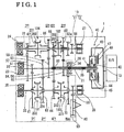
- Fig. 1 is a schematic view showing an overall construction of a dual clutch transmission according to an embodiment disclosed here;
- Fig. 2 is a schematic view of a dual clutch and a damper according to the embodiment disclosed here.
- DCT dual clutch transmission
- the dual clutch transmission 1 includes a first input shaft 21, a second input shaft 22, a first output shaft 31, and a second output shaft 32 which are disposed within a case10. Further, a dual clutch 40, drive gears 51 to 57 for each of shift stages, a finial-speed reduction drive gears 58, 68, driven gears 61 to 67 for each of the shift stages, a reverse gear 70, and a ring gear 80 are provided in the case 10.
- the case 10 includes a transmission case 11 and a clutch housing 12.
- the transmission case 11 pivotally supports shafts via bearings 23 to 25, respectively.
- the clutch housing 12 is positioned to face an end surface of the transmission case 11 and is fixed to the transmission case 11 by bolts.
- the clutch housing 12 pivotally supports the shafts via bearings 26 to 28, respectively, and houses the dual clutch 40 therein.
- needle bearings i.e., serving as a bearing
- ball bearing 26 i.e., serving as a bearing
- a second speed drive gear 52, a fourth speed drive gear 54 with larger diameter, and a sixth speed drive gear 56 are provided on the first input shaft 21.Further, a connection portion connected to the first clutch disc 44 of the dual clutch 40 is formed on the first input shaft 21 in a form of a spline.
- the second input shaft 22 which is a solid shaft, is rotatably supported by a ball bearing (i.e.,serving as the bearing) 23 relative to the transmission case 11. That is, the second input shaft 22 is arranged coaxially with the first input shalt 21to be penetrated through the first input shaft 21and to be relatively rotatable. Portions to support the bearings and plural external splines are formed on an external peripheral surface of the second input shaft 22. A first speed drive gear 51 and a third speed drive gear 53 having a larger diameter are directly formed on the second input shaft 22. A fifth speed drive gear 55 and a seventh speed drive gear 57 are fitted onto the external spline formed on the external peripheral surface of the second input shaft 22 by means of a spline engagement. Further, an end portion of the second input shaft 22 is formed with a connection portion connected to a second clutch disc 47 of the dual clutch 40 in a form of spline. A hollow shaft may, alternatively, be applied as the second input shaft 22.
- the first output shaft 31 is supported by the bearings 24, 27 to be rotatable relative to the transmission case 11 and the clutch housing 12, and is arranged in parallel to the second input shaft 22 in the transmission case 11.
- the final speed reduction drive gear 68, portions supporting the bearings and plural external splines are formed on an external peripheral surface of the first output shaft 31.
- Hubs 201 each provided for shift clutches 102, 104, respectively, are fitted to the external spline of the first output shaft 31 by means of spline fitting.
- the final speed reduction drive gear 68 is meshed with the ring gear 80 of a differential mechanism.
- the first output shaft 31 is formed with a support portion which idly supports a second speed driven gear 62, a fifth speed driven gear 65, a sixth speed driven gear 66, and a seventh speed driven gear 67.
- the second output shaft 32 is supported by the bearings 25, 28 to be rotatable relative to the transmission case 11 and the clutch housing 12, and is arranged in parallel with the second Input shaft 22 in the transmission case 11.
- the final speed reduction drive gear 58 is formed on an external peripheral surface of the second output shaft 32. Further, portions to support bearings and plural external splines are formed on the external peripheral surface of the second output shaft 32.
- the hub 201 for each shift clutch 101, 103 is press-fitted to the external spline of the second output shaft 32 by a spline engagement.
- the final speed reduction drive gear 58 is meshed with the ring gear 80 of the differential mechanism.
- the second output shaft 32 is formed with support portions which Idly support a first speed driven gear 61,a third speed driven gear 63, a fourth speed driven gear 64, and the reverse gear 70.
- the reverse gear 70 is idly provided at the support portion of the reverse gear 70 formed on the second output shaft 32. According to the embodiment, the reverse gear 70 is always engaged with a small diameter gear 62a which is integrally formed with the second speed driven gear 62.
- Each of the shift clutches 101, 102,103,104 includes the hub 201 and a sleeve202.
- the hub 201 is formed in a disc shape having a hollow, which is formed with an internal spline and an external spline, and is fitted onto the external spline of the first output shaft 31, or the second output shaft 32 by means of the spline engagement.
- the sleeve 202 is geared with the external spline of the hub 201 to be axially slidable relative to the hub 201.
- the sleeve 202 When the sleeve 202 axially slides relative to the hub 201, the sleeve 202 is configured to engage with a synchromesh gear portion of the reverse gear 70 or one of the driven gears 61 to 67. Namely, by the sliding movement in the axial direction, the sleeve 202 switches an engaged state and a disengaged state with the synchromesh gear provided at the driven gears 61 to 67 and the reverse gear 70,to selectively connect one of the first speed driven gear 61, the third speed driven gear 63, the fourth speed driven gear 64, and the reverse gear 70 to the second output shaft 32 , or one of the second speed driven gear 62, the fifth speed driven gear 65, the sixth speed driven gear 66, and the seventh speed driven gear 67 to the first output shaft 31 .
- the ring gear 80 is engaged with the final speed reduction drive gear 58 and the final speed reduction drive gear 68 so as to be always rotatably connected to the first output shaft 31 and the second output shaft 32.
- the ring gear 80 is connected to driving wheels via a rotational shaft pivotally supported by the case 10 and the differential mechanism. That is, the ring gear 80 of the differential mechanism serves as a final gear for the transmission.
- the dual clutch 40 which is a dry type clutch, includes a clutch frame 43, a first clutch disc 44, a first pressure plate 45, a first operational mechanism 46, a second clutch disc 47, a second pressure plate 48, and a second operational mechanism 49.
- the first clutch disc 44 transmits a torque (rotational driving force) of an internal combustion engine (i.e.,serving as a prime mover) E/G to the first input shaft 21.
- the second clutch disc 47 transmits a driving force of the internal combustion engine E/G to the second input shaft 22.
- the dual clutch 40 is housed in the clutch housing 12 at a right side in Fig. 1 , and a rotational shaft of the dual clutch 40 is provided coaxially to the first input shaft 21 and the second-input shaft 22.
- the first clutch disc 44 is spline fitted onto a connecting shaft portion of the first input shaft 21 to be axially movable while being restricted with a rotational movement.
- the second clutch disc 47 is spline fitted onto a connecting shaft portion of the second input shaft 22 to be axially movable while being restricted with a rotational movement.
- a high speed shift change is performed by switching the connections with the internal combustion engine E/G by consecutively operating the first and second clutch discs 44, 47 relative to the first and second input shafts 21, 22 based on control commands from a vehicle by a method which will be explained hereinafter.
- the clutch frame 43 is rotatably mounted on the first input shaft 21, and is rotatably connected to the internal combustion engine E/G while a rotational direction is limited, Thus, the clutch frame 43 integrally rotates with the internal combustion engine E/G.
- the clutch frame 43 includes a first wall 43a and a second wall 43b which are connected to each other as shown in Fig. 2 .
- the first wall 43a and the second wall 43b are each formed in a disc shape.
- the second wall 43b is positioned at a side closer to the internal combustion engine E/G keeping a predetermined distance from the first wall 43a in an axial direction on the first input shaft 21.
- Internal periphery portions of the first wall 43a and the second wall 43b are rotatably supported by bearings (e.g.,ball bearings) 41, 42, respectively.
- stopper plates i.e.,each serving as a restriction member
- a C-ring fitted into a groove formed on an external peripheral surface of the first input shaft 21 serves as the stopper plate 81, 82.
- the stopper plates 81, 82 are provided at the bearings 41, 42, respectively, however, the construction is not limited thereto. For example, only the stopper plate 82 may be provided, and adequate effects can be attained. Alternatively, only the stopper plate 81 may be provided.
- the first clutch disc 44 is a frictional plate formed in a disc shape.
- the first clutch disc 44 is pressed onto a plane surface of the first wall 43a of the clutch frame 43 facing the internal combustion engine E/G to engage with-the first wall 43a by a frictional force so as to integrally rotate with the first wall 43a.
- the first clutch disc 44 is positioned between the first wall 43a and the second wall 43b.
- a spline is formed on an internal peripheral portion 44a of the first clutch disc 44.
- the spline of the first clutch disc 44 is engaged with a spline formed on the external peripheral surface of the first input shaft 21, thereby restricting the rotation of the first clutch disc 44 and allowing the movement of the first clutch disc 44 in the axial direction.
- the first pressure plate 45 is configured to press the first clutch disc 44 towards the first wall 43a in order to engage the first clutch disc 44 with the first wall 43a.
- the first pressure plate 45 is positioned between the first clutch disc 44 and the second wall 43b to be movable in the axial direction.
- the first pressure plate 45 is formed in a disc plate shape, presses the first clutch disc 44 towards the first wall 43a by means of the first operational mechanism 46, and sandwiches the first clutch disc 44 together with the first wall 43a.
- the first pressure plate 45 is supported by the first operational mechanism 46.
- the first operational mechanism 46 is configured to press the first clutch disc 44 towards the first wall 43a via the first pressure plate 45 to move the first clutch disc 44 forward or backward.
- the first operational mechanism 46 includes a link portion 71 and a cylinder portion 72,
- the link portion 71 includes a lever mechanism having a lever 71a, a connection lever 71d, and a projection portion 77.
- the projection portion 77 supporting a fulcrum 71e of the lever 71 a is formed on a wall surface of the first wall 43a facing the transmission.
- An application point portion 71b of force of the lever 71a serving as a point of application of the lever mechanism is connected to the first pressure plate 45 by the connection lever 71d.
- a tip end of a cylinder piston 72b of a cylinder 72a of the cylinder portion 72 is attachable to and detachable from a point of effort portion 71c of the lever 71a (i.e., serving as a point of effort of the lever).
- the connection lever71d is supported by the first wall 43a by means of a plate shaped spring member which restricts a rotational movement and allows a linear movement of the connection lever 71d in an axial direction.
- the link portion 71 including the connection lever 71d and the first pressure plate 45 connected to the connection lever 71d are integrally rotated with the first wall 43a.
- the cylinder portion 72 includes an electric motor supported by the clutch housing 12 and the cylinder 72a.
- the electric motor converts a rotational movement to a linear movement to move the tip end of the cylinder piston 72b of the cylinder 72a in a forward or backward direction. Then, by pressing the point of effort portion 71 c of the lever 71a by the tip end of the cylinder piston 72b towards the internal combustion E/G, the first pressure plate 45 is moved towards the first wall 43a to press the first clutch disc 44 in the axial direction so that the first clutch disc 44 and the first wall 43a are engaged.
- the second clutch disc 47 is a frictional plate formed in a disc shape.
- the second clutch disc 47 is pressed onto a plane surface of the second wall 43b of the clutch frame 43 facing the internal combustion engine E/G to engage with the second wall 43b by a frictional force so as to integrally rotate with the second wall 43b.
- the second clutch disc 47 is positioned closer to the internal combustion engine E/G relative to the second wall 43b.
- a spline is formed on an internal peripheral portion 47a of the second clutch disc 47.
- the spline of the second clutch disc 47 is engaged with a spline formed on the external peripheral surface of the second input shaft 22, thereby restricting the rotation of the second clutch disc 47 and allowing the movement of the second clutch disc 47 in the axial direction.
- the second pressure plate 48 is configured to press the second clutch disc 47 towards the second wall 43b in order to engage the second clutch disc 47 with the second wall 43b.
- the second pressure plate 48 is positioned closer to the internal combustion engine E/G relative to the second clutch disc 47 to be movable in the axial direction.
- the second pressure plate 48 is formed in a disc plate shape, presses the second clutch disc 47 towards the second wall 43b by means of the second operational mechanism 49, and sandwiches the second clutch disc 47 together with the second wall 43b.
- the second pressure plate 46 is supported by the second operational mechanism 49.
- the second operational mechanism 49 is configured to press the second clutch disc 47 towards the second wall 43b via the second pressure plate 48 to move the second clutch disc 47 forward or backward.
- the second operational mechanism 49 includes a link portion 73 and a cylinder portion74.
- the link portion 73 includes a lever mechanism having a lever 73a, connection lever 73d, and a projection portion 78.
- the projection portion 78 supporting a fulcrum 73e of the lever 73a is formed on a wall surface of the first wall 43a facing the transmission.
- An application point portion 73b of force of the lever 73a serving as a point of application of the lever mechanism is connected to the second pressure plate 48 by the connection lever73d.
- a tip end of a cylinder piston 74b of a cylinder 74a of the cylinder portion 74 is attachable to and detachable from a point of effort portion 73c of the lever 73a (i.e., serving as a point of effort of the lever).
- connection lever 73d is supported by the second wall 43b by means of a plate shaped spring member which restricts a rotational movement and allows a linear movement of the connection lever 73d in an axial direction.
- link portion 73 including the connection lever 73d and the second pressure plate 48 connected to the connection lever 73d are integrally rotated with the second wall 43b.
- the cylinder portion 74 includes an electric motor supported by the clutch housing 12 and the cylinder 74a.
- the electric motor converts a rotational movement to a linear movement to move the tip end of the cylinder piston 74b of the cylinder 74a in a forward or backward direction. Then, by pressing the point of effort portion 73c of the lever 73a by the tip end of the cylinder piston 74b towards the internal combustion E/G, the second pressure plate 48 is moved towards the second wall 43b to press the second clutch disc 47 in the axial direction so that the second clutch disc 47 and the second wall 43b are engaged.
- the clutch frame 43 is connected to an output shaft 13 of the internal combustion engine E/G via a flywheel 94, a damper 75 serving as an oscillation absorbing mechanism, and a connecting arm 76.
- the damper 75 is arranged between the connecting arm 76 and the flywheel 94 in order to absorb oscillations generated in an axial direction and an orthogonal direction relative to the output shaft of the internal combustion engine E/G.
- a coil spring 75a is compressingly in contact with the damper 75 so that a neutral position at the clutch frame 43 side is maintained by a reaction force of the coil spring 75a.
- the coil spring 75a When a vibration (oscillation) in a rotational direction is transmitted from the internal combustion engine E/G, the coil spring 75a is compressed to absorb the vibration, and the coil spring 75a returns to an original state when the vibration converges to restore the clutch frame 43 side to be in the neutral state. Further, when the vibration in a rotational axis direction is generated, the vibration is absorbed by a play for assembling the damper 75. Thus, the vibration is absorbed by the damper 75 even if the vibration is generated at the internal combustion engine E/G in the axial direction and in the orthogonal direction, the clutch frame 43 is unlikely influenced by the vibration and the vibration (oscillation) is not generated at the first wall 43a and the second wall 43b of the clutch frame 43. Accordingly, the first wall 43a and the second wall 43b, and the first clutch disc 44 and the second clutch disc 47 are favorably engaged without oscillation,
- a controlling device operates the first and second clutch discs 44, 47 of the dual clutch 40 and the shift clutches 101 to 104 in accordance with vehicle operational states, for example, a throttle opening degree, an engine rotation speed, and a vehicle speed.
- vehicle operational states for example, a throttle opening degree, an engine rotation speed, and a vehicle speed.
- the first and second clutch discs 44, 47 of the dual clutch 40 are disengaged and the shift clutches 101 to 104 are positioned at each of the neutral positions.
- the control device slides the sleeve 202 of the shift clutch 101 to engage the sleeve 202 with the synchromesh gear portion of the driven gear 61 of the speed gears, and controls other clutches to be at the neutral portions to establish a gear arrangement for a first speed gear stage.
- the control device When a rotation speed of the internal combustion engine E/G exceeds a predetermined speed upon an increase in the throttle opening degree, the control device operates the second clutch disc 47 of the dual clutch 40 in accordance with the level of throttle opening degree to gradually increase an engaging force so that the second clutch disc 47 is rotatably connected to the second input shaft 22 and the second output shaft 32 including the first speed gear set 51, 61.
- control device operates the electric motor of the second operational mechanism 49 to operate the second clutch disc 47, thus to move the cylinder piston 74b of the cylinder portion 74 in a forward direction, that is, towards the internal combustion engine E/G. Thereafter, the control device controls to contact the tip end of the cylinder piston 74b to the point of effort portion 73c of the lever 73a of the link portion 73 and further moves the cylinder piston 74b forward.
- the lever 73a whose point of effort (i.e., the point of effort portion 73c) is pressed towards the internal combustion engine E/G rotates about a fulcrum (i.e., the projection portion 78) provided at the first wall 43a so that the point of application portion 73b moves to be away from the first wall 43a. Because the point of application portion 73b is connected to the second pressure plate 4B by means of the connection lever 73d, the movement of the point of application portion being away from the first wall 43a allows the second pressure plate 48 to move towards the second wall 43b, and the second pressure plate 48 pushes the second clutch disc 47 towards the second wall 43b.
- a fulcrum i.e., the projection portion 78
- the second clutch disc 47 is pressed to the second wall 43b and is positioned between the second pressure plate 48 and the second wall 43b to integrally rotate. Then, the rotational force of the internal combustion engine E/G is transmitted to the second input shaft 22 to which the second clutch disc 47 is rotatably connected.
- the second wall 43b which is pressed by the second clutch disc 47, is integrally connected to the first wall 43a to form the clutch frame 43 to have high rigidity, and is mounted to the first input shaft 21, which has a larger diameter and a higher rigidity than the second input shaft 22, via the bearings 42, 41 together with the first wall 43a. Accordingly, because the clutch frame 43 and the first input shaft 21 stably support the second wall 43b without bending even if the second wall 43b is pushed by the second clutch disc 47, there is no possibility of abrasion due to an undesired partial contact of the second clutch disc 47 to the second wall 43b because of an unstable engagement between the second clutch disc 47 and the second wall 43b.
- the driving force of the internal combustion engine E/G is transmitted from the second wall 43b (clutch frame 43) to the ring gear 80 of the differential mechanism via the second clutch disc 47, the second input shaft 22, the first speed gear set 51, 61, the shift clutch 101, the second output shaft 32, and the final speed reduction driving gear 58, in the mentioned order, and thus the vehicle travels in the first speed.
- the control device slides the sleeve 202 of the shift clutch 102 to engage the sleeve 202 with the synchromesh gear portion of the driven gear 62 of the speed gears to establish a gear arrangement for a second speed gear stage. Then, the dual clutch 40 is switched to the first clutch disc 44 to switch to a second speed traveling, and the sleeve 202 of the shift clutch 101 is disengaged thereafter.
- control device activates the electric motor of the first operational mechanism 46 in order to switch the dual clutch 40 to connect the first clutch disc 44, and controls the cylinder piston 72b of the cylinder portion 72 to move forward towards the internal combustion engine E/G. Then, the control device controls the cylinder piston 72b so that the tip end thereof contacts the point of effort portion 71c of the lever 71a of the link portion 71 and the cylinder piston 72b further moves forward.
- the lever 71a whose point of effort (i.e., the point of effort portion 71c) is pressed towards the internal combustion engine E/G rotates about a fulcrum-(i.e., the projection portion 77) provided at the first wall 43a so that the point of application portion 71 b moves to be away from the first wall 43a. Because the point of application portion 71 b is connected to the first pressure plate 45 by means of the connection lever 71d, the movement of the point of application portion 71 b being away from the first wall 43a allows the first pressure plate 45 to move towards the first wall 43a, and the first pressure plate 45 pushes the first clutch disc 44 towards the first wall 43a.
- the first clutch disc 44 is pressed to the first wall 43a and is positioned between the first pressure plate 45 and the first wall 43a to integrally rotate. Then, the rotational force of the internal combustion engine E/G is transmitted to the first input shaft 21 to which the first clutch disc 44 is rotatably connected.
- the driving force of the internal combustion engine E/G is transmitted from the first wall 43a (clutch frame 43) to the ring gear 80 of the differential mechanism via the first clutch disc 44, the first input shaft 21, the second speed gear set 52, 62, the shift clutch 102, the first output shaft 31, and the final speed reduction driving gear 68, in the mentioned order, and thus the vehicle travels in the second speed.
- the control device controls to consecutively select speed gears appropriate for the operational state of the vehicle, and selects the first clutch disc 44 and the second clutch disc 47 alternately, so that the vehicle travels with the selection of a speed gear which is appropriate for the traveling state,
- the control device detects that the shift lever is at the reverse position and slides the sleeve 202 of the shift dutch 103 to engage the sleeve 202 with the synchromesh gear portion of the reverse gear 70, and controls other clutches to be at the neutral portions to establish a gear arrangement for a reverse gear stage.
- the reverse gear 70 is always engaged with the small diameter gear 62a which is integrally formed with the driven gear 62 of the speed gears. Then, as explained above, when the reverse gear 70 is selected, the first clutch disc 44 is selected to connect to the first input shaft 21.
- the driving force of the internal combustion engine E/G is transmitted from the first wall 43a (clutch frame 43) to the ring gear 80 of the differential mechanism via the first clutch disc 44, the first input shaft 21, the second speed gear set 62, 62, 62a, the reverse gear 70, the shift clutch 103, the second output shaft 32, and the final speed reduction driving gear 58, in the mentioned order, and thus the vehicle starts moving in a reverse direction.
- the clutch frame 43 rotatably connected to the internal combustion engine E/G serving as the prime mover is supported by the first input shaft 21 which has a large diameter and has a high flexural rigidity. Further, because the clutch frame 43 is formed by connecting the first wall 43a and the second wall 43b, a strength/rigidity of the clutch frame 43 per se is enhanced. Accordingly, even if the clutch frame 43 and the first input shaft 21 receive the oscillation of the internal combustion engine E/G, the oscillation (flexure) of the clutch frame 43 and the first input shaft 21 is effectively restrained.
- first wall 43a or the second wall 43b effectively receives the pressing force as the clutch frame 43 having high rigidity and by the first input shaft 21 having high flexural rigidity when the first clutch disc 44 or the second clutch disc 47 is rotatably connected while pressing the first wall 43a or the second wall 43b, there is no possibility that the first wall 43a or the second wall 43b is bent. Accordingly, there is no possibility of abrasion at the engaging surfaces of the clutch disc and the wall because of an unstable engagement between the first wall 43a and the first clutch disc 44 or between the second clutch disc 47 and the second wall 43b, and thus the rotational force of the internal combustion engine E/G can be effectively transmitted to the input shafts 21, 22.
- the clutch frame 43 is rotatably connected to the internal combustion engine E/G via the damper 75 serving as the oscillation absorbing mechanism, the oscillation (vibration) of the internal combustion engine E/G is restrained and is not transmitted to the first wall 43a and/or the second wall 43b. Accordingly, the dual clutch 40 transmits the rotational force (torque) of the internal combustion E/G to each of the input shafts 21, 22 further effectively.
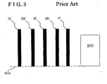
- a first pressure plate P1 is arranged on an axis close to an engine E/G.
- a first clutch disc CD1 is arranged coaxially to the first pressure plate P1.
- a center plate CP is arranged adjacent to the first clutch disc CD1 in an axial direction.
- a second clutch disc CD2 is arranged coaxially to the first clutch disc CD1 so that the center plate CP is sandwiched by the second clutch disc CD2 and the first clutch disc CD1.
- a second pressure plate P2 is arranged adjacent to the second clutch disc CD2 in the axial direction.
- the first clutch disc CD1 and the second clutch disc CD2 are pressed to contact the first pressure plate P1 and the second pressure plate P2, respectively, and to contact the center plate CP.
- the both side surfaces of the first clutch disc CD1 and the both side surfaces of the second clutch disc CD2 are heated by a frictional contact with the first pressure plate P1 and the second pressure plate P2, respectively, and with the center plate CP, thus, a torque is not stabilized.
- the construction of the embodiment as shown in Fig.
- a portion of the flrst clutch disc 44 pressed by the first pressure plate 45 corresponds to one side surface of the first clutch disc 44
- a portion of the second clutch disc 47 pressed by the second pressure plate 48 corresponds to one side surface of the second clutch disc 47.
- the first pressure plate 45 and the second wall 43b are positioned keeping a predetermined length of distance therebetween.
- the first clutch disc 44 and the second clutch disc 47 are not affected by the heat generated due to being pressed on the both side surfaces thereof. Accordingly, a frictional coefficient of the first clutch disc 45 and the second clutch disc 47 can be estimated with high precision, and the torque is stabilized.
- a frictional plate with a single plate is applied as the first clutch disc 44 and the second clutch disc 47.
- the construction of the first clutch disc 44 and the second clutch disc 47 is not limited, and any types of multiple plate clutches with multiple frictional plates are applicable. Namely, for example, multiple clutch discs and multiple movable bodies are arranged alternately so that each of the movable bodies is positioned between the adjacent clutch discs to be pressed by a pressure plate. The same effects and advantage from the embodiment can be attained with this structure.
- the internal combustion engine E/G is applied as the prime mover
- the construction of the prime mover is not limited.
- an electric motor may be applied.
- the cylinder portions 72, 74 for operating the first clutch disc 44 and the second clutch disc 47 are driven by the electric motor, however, the construction for actuating the cylinder portions 72, 74 is not limited.
- a cylinder utilizing an air pressure or a direct drive electric motor may be applied.
- the dual clutch transmission is applied to an automobile, however, the dual clutch transmission of the disclosure is applicable to other vehicles, for example, ships, boats, trains, and aircrafts.
Landscapes
- Engineering & Computer Science (AREA)
- General Engineering & Computer Science (AREA)
- Mechanical Engineering (AREA)
- Mechanical Operated Clutches (AREA)
- Structure Of Transmissions (AREA)
Claims (4)
- Transmission à double embrayage, comprenant :un premier arbre (21) d'entrée supporté en rotation par un boîtier (10), le premier arbre (21) d'entrée comprenant un creux ;un deuxième arbre (22) d'entrée pénétrant à travers le premier arbre (21) d'entrée sur un axe commun avec le premier arbre (21) d'entrée pour être supporté par le boîtier;un double embrayage (40) transmettant de manière sélective une force d'entraînement rotative d'un premier mécanisme (E/G) au premier arbre (21) d'entrée ou au second arbre (22) d'entrée, le double embrayage (40) comprenant:une coque d'embrayage (43) comprenant une première paroi (43a) et une seconde paroi (43b) qui sont supportées de manière rotative sur le premier arbre (21) d'entrée et qui sont reliées l'une à l'autre tout en gardant une distance entre elles le long d'une direction axiale du premier arbre (21) d'entrée, la coque d'embrayage (43) étant restreinte à se déplacer vers le premier mécanisme;un premier disque d'embrayage (44) agencé entre la première paroi (43a) et la seconde paroi (43b) pour être mobile dans la direction axiale;une première plaque (45) de pression agencée entre le premier disque d' embrayage (44) et la seconde paroi (43b) pour être mobile dans la direction axiale;un premier mécanisme (46) opérationnel déplaçant la première plaque (45) de pression vers la première paroi (43a) ;un second disque d' embrayage (47) positionné plus près du premier mécanisme par rapport à la seconde paroi (43b) pour être mobile dans la direction axiale;une seconde plaque (48) de pression agencée entre le second disque d'embrayage (47) et le premier mécanisme pour être mobile dans la direction axiale ; etun second mécanisme (49) opérationnel déplaçant la seconde plaque (48) de pression vers la seconde paroi (43b).
- Transmission à double embrayage selon la revendication 1, dans laquelle la coque d'embrayage (43) est reliée au premier mécanisme (E/G) par l'intermédiaire d'un mécanisme (75) d'absorption d'oscillation.
- Transmission à double embrayage selon l'une ou l'autre des revendications 1 ou 2, dans laquelle la première paroi (43a) et la seconde paroi (43b) de la coque d'embrayage (43) sont supportées en rotation sur le premier arbre (21) d'entrée tout en étant restreint de ne pas se déplacer par rapport au premier arbre d'entrée dans la direction axiale vers le premier mécanisme (E/G).
- Transmission à double embrayage selon la revendication 3, comprenant en outre:au moins un organe restrictif (81,82) agencé sur le premier arbre d'entrée pour restreindre la coque d'embrayage (43) de se déplacer vers le premier mécanisme (E/G).
Applications Claiming Priority (1)
| Application Number | Priority Date | Filing Date | Title |
|---|---|---|---|
| JP2010246881A JP5528302B2 (ja) | 2010-11-02 | 2010-11-02 | デュアルクラッチ式自動変速機 |
Publications (4)
| Publication Number | Publication Date |
|---|---|
| EP2447560A2 EP2447560A2 (fr) | 2012-05-02 |
| EP2447560A3 EP2447560A3 (fr) | 2013-06-19 |
| EP2447560B1 true EP2447560B1 (fr) | 2014-06-11 |
| EP2447560B8 EP2447560B8 (fr) | 2014-07-16 |
Family
ID=44862809
Family Applications (1)
| Application Number | Title | Priority Date | Filing Date |
|---|---|---|---|
| EP11187259.4A Not-in-force EP2447560B8 (fr) | 2010-11-02 | 2011-10-31 | Transmission à embrayage double |
Country Status (3)
| Country | Link |
|---|---|
| EP (1) | EP2447560B8 (fr) |
| JP (1) | JP5528302B2 (fr) |
| CN (1) | CN102562844B (fr) |
Families Citing this family (5)
| Publication number | Priority date | Publication date | Assignee | Title |
|---|---|---|---|---|
| CN104482172B (zh) * | 2014-12-18 | 2017-09-15 | 重庆隆旺机电有限责任公司 | 双离合变速器 |
| KR101745157B1 (ko) | 2015-10-26 | 2017-06-08 | 현대자동차주식회사 | 차량용 주행 제어방법 |
| CN112747112B (zh) * | 2019-10-30 | 2022-05-13 | 比亚迪股份有限公司 | 离合器、变速器、动力系统以及车辆 |
| CN112744065B (zh) * | 2019-10-30 | 2022-10-18 | 比亚迪股份有限公司 | 混合动力系统以及具有其的车辆 |
| CN111059168A (zh) * | 2020-01-08 | 2020-04-24 | 尚尔航 | 一种杠杆控制的离合器及变速装置 |
Family Cites Families (11)
| Publication number | Priority date | Publication date | Assignee | Title |
|---|---|---|---|---|
| GB1517516A (en) * | 1974-11-27 | 1978-07-12 | Automotive Prod Co Ltd | Clutches |
| JPH08320054A (ja) * | 1995-05-24 | 1996-12-03 | Toyota Motor Corp | 歯車式変速装置 |
| DE10134118B4 (de) * | 2001-07-13 | 2013-02-21 | Volkswagen Ag | Doppelkupplung |
| DE102004001278B4 (de) * | 2004-01-07 | 2015-08-13 | Volkswagen Ag | Doppelkupplungsgetriebe für ein Kraftfahrzeug |
| ATE415572T1 (de) * | 2004-09-03 | 2008-12-15 | Luk Lamellen & Kupplungsbau | Drehmomentübertragungseinrichtung |
| DE102006045163A1 (de) * | 2006-09-25 | 2008-04-03 | Robert Bosch Gmbh | Doppelkupplung für ein Doppelkupplungsgetriebe |
| DE102007047671A1 (de) * | 2007-10-05 | 2009-04-09 | Daimler Ag | Doppelkupplungsgetriebevorrichtung |
| DE102009002351B4 (de) * | 2009-04-14 | 2019-10-10 | Zf Friedrichshafen Ag | Doppelkupplungsgetriebe |
| US8302500B2 (en) * | 2009-04-22 | 2012-11-06 | GM Global Technology Operations LLC | Dual clutch transmission |
| KR101132458B1 (ko) * | 2009-04-24 | 2012-03-30 | 강명구 | 듀얼 전위기어를 배치한 다중 클러치 변속기 |
| CN201502668U (zh) * | 2009-07-21 | 2010-06-09 | 上海汽车集团股份有限公司 | 双离合器变速器 |
-
2010
- 2010-11-02 JP JP2010246881A patent/JP5528302B2/ja not_active Expired - Fee Related
-
2011
- 2011-10-31 EP EP11187259.4A patent/EP2447560B8/fr not_active Not-in-force
- 2011-11-02 CN CN201110344212.8A patent/CN102562844B/zh not_active Expired - Fee Related
Also Published As
| Publication number | Publication date |
|---|---|
| JP2012097852A (ja) | 2012-05-24 |
| EP2447560A3 (fr) | 2013-06-19 |
| EP2447560B8 (fr) | 2014-07-16 |
| EP2447560A2 (fr) | 2012-05-02 |
| CN102562844A (zh) | 2012-07-11 |
| JP5528302B2 (ja) | 2014-06-25 |
| CN102562844B (zh) | 2015-12-09 |
Similar Documents
| Publication | Publication Date | Title |
|---|---|---|
| US8156837B2 (en) | Multiple-ratio transmission with concentric offset shift forks | |
| CN113090753B (zh) | 换档机构、两档换档系统及车辆 | |
| JP5409804B2 (ja) | 駆動アッセンブリ | |
| US7661331B2 (en) | Shifting device for dual clutch transmission | |
| EP2738421B1 (fr) | Transmission et véhicule électrique comportant cette transmission | |
| EP2405162B1 (fr) | Appareil de verrouillage de la position de stationnement pour une boîte de vitesses | |
| CN104334922B (zh) | 车辆用传动装置 | |
| WO2009131077A1 (fr) | Dispositif de transmission de puissance hybride | |
| WO2010038338A1 (fr) | Dispositif de transmission de puissance | |
| EP2447560A2 (fr) | Transmission à embrayage double | |
| CN102139634A (zh) | 用于汽车的双离合器 | |
| CN113586697A (zh) | 扭矩管理器 | |
| WO2010101168A1 (fr) | Transmission d'énergie | |
| KR101103969B1 (ko) | Dct 클러치 작동기구 | |
| KR20090021263A (ko) | 기어시프트 인터록 | |
| EP2110578A2 (fr) | Appareil de transmission automatique à embrayage double | |
| JPH0792115B2 (ja) | 二重質量フライホイール | |
| KR900009134B1 (ko) | 치차식 변속기의 후진구조 | |
| KR101647529B1 (ko) | 이중 포크 제어 장치를 포함하는 이중 클러치 메커니즘 | |
| JP6699353B2 (ja) | 変速機 | |
| CN219263108U (zh) | 一种采用双离合器的电动汽车两档变速箱 | |
| JP2002048198A (ja) | 変速機 | |
| US20040051320A1 (en) | Multifunctional clutch actuating device | |
| CN111536210A (zh) | 变速器、双离合机构及两挡电桥驱动系统 | |
| KR100597351B1 (ko) | 후륜 구동용 수동 변속기 |
Legal Events
| Date | Code | Title | Description |
|---|---|---|---|
| PUAI | Public reference made under article 153(3) epc to a published international application that has entered the european phase |
Free format text: ORIGINAL CODE: 0009012 |
|
| AK | Designated contracting states |
Kind code of ref document: A2 Designated state(s): AL AT BE BG CH CY CZ DE DK EE ES FI FR GB GR HR HU IE IS IT LI LT LU LV MC MK MT NL NO PL PT RO RS SE SI SK SM TR |
|
| AX | Request for extension of the european patent |
Extension state: BA ME |
|
| PUAL | Search report despatched |
Free format text: ORIGINAL CODE: 0009013 |
|
| AK | Designated contracting states |
Kind code of ref document: A3 Designated state(s): AL AT BE BG CH CY CZ DE DK EE ES FI FR GB GR HR HU IE IS IT LI LT LU LV MC MK MT NL NO PL PT RO RS SE SI SK SM TR |
|
| AX | Request for extension of the european patent |
Extension state: BA ME |
|
| RIC1 | Information provided on ipc code assigned before grant |
Ipc: F16D 21/06 20060101AFI20130513BHEP |
|
| GRAP | Despatch of communication of intention to grant a patent |
Free format text: ORIGINAL CODE: EPIDOSNIGR1 |
|
| 17P | Request for examination filed |
Effective date: 20131015 |
|
| RBV | Designated contracting states (corrected) |
Designated state(s): AL AT BE BG CH CY CZ DE DK EE ES FI FR GB GR HR HU IE IS IT LI LT LU LV MC MK MT NL NO PL PT RO RS SE SI SK SM TR |
|
| INTG | Intention to grant announced |
Effective date: 20131126 |
|
| GRAS | Grant fee paid |
Free format text: ORIGINAL CODE: EPIDOSNIGR3 |
|
| GRAA | (expected) grant |
Free format text: ORIGINAL CODE: 0009210 |
|
| RAP1 | Party data changed (applicant data changed or rights of an application transferred) |
Owner name: EXEDY CORPORATION Owner name: AISIN SEIKI KABUSHIKI KAISHA |
|
| AK | Designated contracting states |
Kind code of ref document: B1 Designated state(s): AL AT BE BG CH CY CZ DE DK EE ES FI FR GB GR HR HU IE IS IT LI LT LU LV MC MK MT NL NO PL PT RO RS SE SI SK SM TR |
|
| REG | Reference to a national code |
Ref country code: GB Ref legal event code: FG4D |
|
| REG | Reference to a national code |
Ref country code: CH Ref legal event code: EP |
|
| REG | Reference to a national code |
Ref country code: DE Ref legal event code: R082 Ref document number: 602011007562 Country of ref document: DE Representative=s name: KRAMER BARSKE SCHMIDTCHEN PATENTANWAELTE PARTG, DE Ref country code: DE Ref legal event code: R082 Ref document number: 602011007562 Country of ref document: DE Representative=s name: KRAMER - BARSKE - SCHMIDTCHEN, DE |
|
| RIN2 | Information on inventor provided after grant (corrected) |
Inventor name: KUMIKAWA, YUKI Inventor name: TANAKA, SATOSHI Inventor name: NAGASAKA, HIROYUKI Inventor name: TOMITA, YUSUKE Inventor name: MORI, KYOSUKE |
|
| REG | Reference to a national code |
Ref country code: IE Ref legal event code: FG4D |
|
| REG | Reference to a national code |
Ref country code: AT Ref legal event code: REF Ref document number: 672419 Country of ref document: AT Kind code of ref document: T Effective date: 20140715 |
|
| REG | Reference to a national code |
Ref country code: DE Ref legal event code: R096 Ref document number: 602011007562 Country of ref document: DE Effective date: 20140724 |
|
| PG25 | Lapsed in a contracting state [announced via postgrant information from national office to epo] |
Ref country code: GR Free format text: LAPSE BECAUSE OF FAILURE TO SUBMIT A TRANSLATION OF THE DESCRIPTION OR TO PAY THE FEE WITHIN THE PRESCRIBED TIME-LIMIT Effective date: 20140912 Ref country code: LT Free format text: LAPSE BECAUSE OF FAILURE TO SUBMIT A TRANSLATION OF THE DESCRIPTION OR TO PAY THE FEE WITHIN THE PRESCRIBED TIME-LIMIT Effective date: 20140611 Ref country code: FI Free format text: LAPSE BECAUSE OF FAILURE TO SUBMIT A TRANSLATION OF THE DESCRIPTION OR TO PAY THE FEE WITHIN THE PRESCRIBED TIME-LIMIT Effective date: 20140611 Ref country code: NO Free format text: LAPSE BECAUSE OF FAILURE TO SUBMIT A TRANSLATION OF THE DESCRIPTION OR TO PAY THE FEE WITHIN THE PRESCRIBED TIME-LIMIT Effective date: 20140911 |
|
| REG | Reference to a national code |
Ref country code: NL Ref legal event code: VDEP Effective date: 20140611 |
|
| REG | Reference to a national code |
Ref country code: AT Ref legal event code: MK05 Ref document number: 672419 Country of ref document: AT Kind code of ref document: T Effective date: 20140611 |
|
| REG | Reference to a national code |
Ref country code: LT Ref legal event code: MG4D |
|
| PG25 | Lapsed in a contracting state [announced via postgrant information from national office to epo] |
Ref country code: LV Free format text: LAPSE BECAUSE OF FAILURE TO SUBMIT A TRANSLATION OF THE DESCRIPTION OR TO PAY THE FEE WITHIN THE PRESCRIBED TIME-LIMIT Effective date: 20140611 Ref country code: SE Free format text: LAPSE BECAUSE OF FAILURE TO SUBMIT A TRANSLATION OF THE DESCRIPTION OR TO PAY THE FEE WITHIN THE PRESCRIBED TIME-LIMIT Effective date: 20140611 Ref country code: HR Free format text: LAPSE BECAUSE OF FAILURE TO SUBMIT A TRANSLATION OF THE DESCRIPTION OR TO PAY THE FEE WITHIN THE PRESCRIBED TIME-LIMIT Effective date: 20140611 Ref country code: RS Free format text: LAPSE BECAUSE OF FAILURE TO SUBMIT A TRANSLATION OF THE DESCRIPTION OR TO PAY THE FEE WITHIN THE PRESCRIBED TIME-LIMIT Effective date: 20140611 |
|
| PG25 | Lapsed in a contracting state [announced via postgrant information from national office to epo] |
Ref country code: EE Free format text: LAPSE BECAUSE OF FAILURE TO SUBMIT A TRANSLATION OF THE DESCRIPTION OR TO PAY THE FEE WITHIN THE PRESCRIBED TIME-LIMIT Effective date: 20140611 Ref country code: SK Free format text: LAPSE BECAUSE OF FAILURE TO SUBMIT A TRANSLATION OF THE DESCRIPTION OR TO PAY THE FEE WITHIN THE PRESCRIBED TIME-LIMIT Effective date: 20140611 Ref country code: CZ Free format text: LAPSE BECAUSE OF FAILURE TO SUBMIT A TRANSLATION OF THE DESCRIPTION OR TO PAY THE FEE WITHIN THE PRESCRIBED TIME-LIMIT Effective date: 20140611 Ref country code: PT Free format text: LAPSE BECAUSE OF FAILURE TO SUBMIT A TRANSLATION OF THE DESCRIPTION OR TO PAY THE FEE WITHIN THE PRESCRIBED TIME-LIMIT Effective date: 20141013 Ref country code: ES Free format text: LAPSE BECAUSE OF FAILURE TO SUBMIT A TRANSLATION OF THE DESCRIPTION OR TO PAY THE FEE WITHIN THE PRESCRIBED TIME-LIMIT Effective date: 20140611 Ref country code: RO Free format text: LAPSE BECAUSE OF FAILURE TO SUBMIT A TRANSLATION OF THE DESCRIPTION OR TO PAY THE FEE WITHIN THE PRESCRIBED TIME-LIMIT Effective date: 20140611 |
|
| PG25 | Lapsed in a contracting state [announced via postgrant information from national office to epo] |
Ref country code: AT Free format text: LAPSE BECAUSE OF FAILURE TO SUBMIT A TRANSLATION OF THE DESCRIPTION OR TO PAY THE FEE WITHIN THE PRESCRIBED TIME-LIMIT Effective date: 20140611 Ref country code: PL Free format text: LAPSE BECAUSE OF FAILURE TO SUBMIT A TRANSLATION OF THE DESCRIPTION OR TO PAY THE FEE WITHIN THE PRESCRIBED TIME-LIMIT Effective date: 20140611 Ref country code: NL Free format text: LAPSE BECAUSE OF FAILURE TO SUBMIT A TRANSLATION OF THE DESCRIPTION OR TO PAY THE FEE WITHIN THE PRESCRIBED TIME-LIMIT Effective date: 20140611 Ref country code: IS Free format text: LAPSE BECAUSE OF FAILURE TO SUBMIT A TRANSLATION OF THE DESCRIPTION OR TO PAY THE FEE WITHIN THE PRESCRIBED TIME-LIMIT Effective date: 20141011 |
|
| REG | Reference to a national code |
Ref country code: DE Ref legal event code: R097 Ref document number: 602011007562 Country of ref document: DE |
|
| PLBE | No opposition filed within time limit |
Free format text: ORIGINAL CODE: 0009261 |
|
| STAA | Information on the status of an ep patent application or granted ep patent |
Free format text: STATUS: NO OPPOSITION FILED WITHIN TIME LIMIT |
|
| PG25 | Lapsed in a contracting state [announced via postgrant information from national office to epo] |
Ref country code: DK Free format text: LAPSE BECAUSE OF FAILURE TO SUBMIT A TRANSLATION OF THE DESCRIPTION OR TO PAY THE FEE WITHIN THE PRESCRIBED TIME-LIMIT Effective date: 20140611 |
|
| 26N | No opposition filed |
Effective date: 20150312 |
|
| PG25 | Lapsed in a contracting state [announced via postgrant information from national office to epo] |
Ref country code: MC Free format text: LAPSE BECAUSE OF FAILURE TO SUBMIT A TRANSLATION OF THE DESCRIPTION OR TO PAY THE FEE WITHIN THE PRESCRIBED TIME-LIMIT Effective date: 20140611 Ref country code: LU Free format text: LAPSE BECAUSE OF FAILURE TO SUBMIT A TRANSLATION OF THE DESCRIPTION OR TO PAY THE FEE WITHIN THE PRESCRIBED TIME-LIMIT Effective date: 20141031 |
|
| REG | Reference to a national code |
Ref country code: CH Ref legal event code: PL |
|
| REG | Reference to a national code |
Ref country code: DE Ref legal event code: R097 Ref document number: 602011007562 Country of ref document: DE Effective date: 20150312 |
|
| REG | Reference to a national code |
Ref country code: IE Ref legal event code: MM4A |
|
| PG25 | Lapsed in a contracting state [announced via postgrant information from national office to epo] |
Ref country code: LI Free format text: LAPSE BECAUSE OF NON-PAYMENT OF DUE FEES Effective date: 20141031 Ref country code: SI Free format text: LAPSE BECAUSE OF FAILURE TO SUBMIT A TRANSLATION OF THE DESCRIPTION OR TO PAY THE FEE WITHIN THE PRESCRIBED TIME-LIMIT Effective date: 20140611 Ref country code: CH Free format text: LAPSE BECAUSE OF NON-PAYMENT OF DUE FEES Effective date: 20141031 |
|
| PG25 | Lapsed in a contracting state [announced via postgrant information from national office to epo] |
Ref country code: IE Free format text: LAPSE BECAUSE OF NON-PAYMENT OF DUE FEES Effective date: 20141031 |
|
| PG25 | Lapsed in a contracting state [announced via postgrant information from national office to epo] |
Ref country code: SM Free format text: LAPSE BECAUSE OF FAILURE TO SUBMIT A TRANSLATION OF THE DESCRIPTION OR TO PAY THE FEE WITHIN THE PRESCRIBED TIME-LIMIT Effective date: 20140611 |
|
| GBPC | Gb: european patent ceased through non-payment of renewal fee |
Effective date: 20151031 |
|
| PG25 | Lapsed in a contracting state [announced via postgrant information from national office to epo] |
Ref country code: CY Free format text: LAPSE BECAUSE OF FAILURE TO SUBMIT A TRANSLATION OF THE DESCRIPTION OR TO PAY THE FEE WITHIN THE PRESCRIBED TIME-LIMIT Effective date: 20140611 Ref country code: BG Free format text: LAPSE BECAUSE OF FAILURE TO SUBMIT A TRANSLATION OF THE DESCRIPTION OR TO PAY THE FEE WITHIN THE PRESCRIBED TIME-LIMIT Effective date: 20140611 |
|
| PG25 | Lapsed in a contracting state [announced via postgrant information from national office to epo] |
Ref country code: TR Free format text: LAPSE BECAUSE OF FAILURE TO SUBMIT A TRANSLATION OF THE DESCRIPTION OR TO PAY THE FEE WITHIN THE PRESCRIBED TIME-LIMIT Effective date: 20140611 Ref country code: GB Free format text: LAPSE BECAUSE OF NON-PAYMENT OF DUE FEES Effective date: 20151031 Ref country code: MT Free format text: LAPSE BECAUSE OF FAILURE TO SUBMIT A TRANSLATION OF THE DESCRIPTION OR TO PAY THE FEE WITHIN THE PRESCRIBED TIME-LIMIT Effective date: 20140611 Ref country code: BE Free format text: LAPSE BECAUSE OF FAILURE TO SUBMIT A TRANSLATION OF THE DESCRIPTION OR TO PAY THE FEE WITHIN THE PRESCRIBED TIME-LIMIT Effective date: 20140611 Ref country code: HU Free format text: LAPSE BECAUSE OF FAILURE TO SUBMIT A TRANSLATION OF THE DESCRIPTION OR TO PAY THE FEE WITHIN THE PRESCRIBED TIME-LIMIT; INVALID AB INITIO Effective date: 20111031 |
|
| REG | Reference to a national code |
Ref country code: FR Ref legal event code: PLFP Year of fee payment: 6 |
|
| REG | Reference to a national code |
Ref country code: FR Ref legal event code: PLFP Year of fee payment: 7 |
|
| PG25 | Lapsed in a contracting state [announced via postgrant information from national office to epo] |
Ref country code: MK Free format text: LAPSE BECAUSE OF FAILURE TO SUBMIT A TRANSLATION OF THE DESCRIPTION OR TO PAY THE FEE WITHIN THE PRESCRIBED TIME-LIMIT Effective date: 20140611 |
|
| REG | Reference to a national code |
Ref country code: FR Ref legal event code: PLFP Year of fee payment: 8 |
|
| PG25 | Lapsed in a contracting state [announced via postgrant information from national office to epo] |
Ref country code: AL Free format text: LAPSE BECAUSE OF FAILURE TO SUBMIT A TRANSLATION OF THE DESCRIPTION OR TO PAY THE FEE WITHIN THE PRESCRIBED TIME-LIMIT Effective date: 20140611 |
|
| PGFP | Annual fee paid to national office [announced via postgrant information from national office to epo] |
Ref country code: FR Payment date: 20190913 Year of fee payment: 9 |
|
| PGFP | Annual fee paid to national office [announced via postgrant information from national office to epo] |
Ref country code: DE Payment date: 20191015 Year of fee payment: 9 |
|
| PGFP | Annual fee paid to national office [announced via postgrant information from national office to epo] |
Ref country code: IT Payment date: 20191009 Year of fee payment: 9 |
|
| REG | Reference to a national code |
Ref country code: DE Ref legal event code: R119 Ref document number: 602011007562 Country of ref document: DE |
|
| PG25 | Lapsed in a contracting state [announced via postgrant information from national office to epo] |
Ref country code: DE Free format text: LAPSE BECAUSE OF NON-PAYMENT OF DUE FEES Effective date: 20210501 Ref country code: FR Free format text: LAPSE BECAUSE OF NON-PAYMENT OF DUE FEES Effective date: 20201031 |
|
| PG25 | Lapsed in a contracting state [announced via postgrant information from national office to epo] |
Ref country code: IT Free format text: LAPSE BECAUSE OF NON-PAYMENT OF DUE FEES Effective date: 20201031 |