EP2447568B1 - Betriebsstrang und herstellungsverfahren für betriebsstrang - Google Patents
Betriebsstrang und herstellungsverfahren für betriebsstrang Download PDFInfo
- Publication number
- EP2447568B1 EP2447568B1 EP10792117.3A EP10792117A EP2447568B1 EP 2447568 B1 EP2447568 B1 EP 2447568B1 EP 10792117 A EP10792117 A EP 10792117A EP 2447568 B1 EP2447568 B1 EP 2447568B1
- Authority
- EP
- European Patent Office
- Prior art keywords
- fitting
- coupling
- cord
- coupling member
- protrusion
- Prior art date
- Legal status (The legal status is an assumption and is not a legal conclusion. Google has not performed a legal analysis and makes no representation as to the accuracy of the status listed.)
- Active
Links
Images










Classifications
-
- F—MECHANICAL ENGINEERING; LIGHTING; HEATING; WEAPONS; BLASTING
- F16—ENGINEERING ELEMENTS AND UNITS; GENERAL MEASURES FOR PRODUCING AND MAINTAINING EFFECTIVE FUNCTIONING OF MACHINES OR INSTALLATIONS; THERMAL INSULATION IN GENERAL
- F16G—BELTS, CABLES, OR ROPES, PREDOMINANTLY USED FOR DRIVING PURPOSES; CHAINS; FITTINGS PREDOMINANTLY USED THEREFOR
- F16G11/00—Means for fastening cables or ropes to one another or to other objects; Caps or sleeves for fixing on cables or ropes
-
- E—FIXED CONSTRUCTIONS
- E06—DOORS, WINDOWS, SHUTTERS, OR ROLLER BLINDS IN GENERAL; LADDERS
- E06B—FIXED OR MOVABLE CLOSURES FOR OPENINGS IN BUILDINGS, VEHICLES, FENCES OR LIKE ENCLOSURES IN GENERAL, e.g. DOORS, WINDOWS, BLINDS, GATES
- E06B9/00—Screening or protective devices for wall or similar openings, with or without operating or securing mechanisms; Closures of similar construction
- E06B9/24—Screens or other constructions affording protection against light, especially against sunshine; Similar screens for privacy or appearance; Slat blinds
- E06B9/26—Lamellar or like blinds, e.g. venetian blinds
- E06B9/28—Lamellar or like blinds, e.g. venetian blinds with horizontal lamellae, e.g. non-liftable
- E06B9/30—Lamellar or like blinds, e.g. venetian blinds with horizontal lamellae, e.g. non-liftable liftable
- E06B9/32—Operating, guiding, or securing devices therefor
- E06B9/326—Details of cords, e.g. buckles, drawing knobs
-
- F—MECHANICAL ENGINEERING; LIGHTING; HEATING; WEAPONS; BLASTING
- F16—ENGINEERING ELEMENTS AND UNITS; GENERAL MEASURES FOR PRODUCING AND MAINTAINING EFFECTIVE FUNCTIONING OF MACHINES OR INSTALLATIONS; THERMAL INSULATION IN GENERAL
- F16G—BELTS, CABLES, OR ROPES, PREDOMINANTLY USED FOR DRIVING PURPOSES; CHAINS; FITTINGS PREDOMINANTLY USED THEREFOR
- F16G13/00—Chains
- F16G13/12—Hauling- or hoisting-chains so called ornamental chains
-
- E—FIXED CONSTRUCTIONS
- E05—LOCKS; KEYS; WINDOW OR DOOR FITTINGS; SAFES
- E05Y—INDEXING SCHEME ASSOCIATED WITH SUBCLASSES E05D AND E05F, RELATING TO CONSTRUCTION ELEMENTS, ELECTRIC CONTROL, POWER SUPPLY, POWER SIGNAL OR TRANSMISSION, USER INTERFACES, MOUNTING OR COUPLING, DETAILS, ACCESSORIES, AUXILIARY OPERATIONS NOT OTHERWISE PROVIDED FOR, APPLICATION THEREOF
- E05Y2201/00—Constructional elements; Accessories therefor
- E05Y2201/60—Suspension or transmission members; Accessories therefor
- E05Y2201/622—Suspension or transmission members elements
- E05Y2201/676—Transmission of human force
-
- E—FIXED CONSTRUCTIONS
- E05—LOCKS; KEYS; WINDOW OR DOOR FITTINGS; SAFES
- E05Y—INDEXING SCHEME ASSOCIATED WITH SUBCLASSES E05D AND E05F, RELATING TO CONSTRUCTION ELEMENTS, ELECTRIC CONTROL, POWER SUPPLY, POWER SIGNAL OR TRANSMISSION, USER INTERFACES, MOUNTING OR COUPLING, DETAILS, ACCESSORIES, AUXILIARY OPERATIONS NOT OTHERWISE PROVIDED FOR, APPLICATION THEREOF
- E05Y2201/00—Constructional elements; Accessories therefor
- E05Y2201/60—Suspension or transmission members; Accessories therefor
- E05Y2201/622—Suspension or transmission members elements
- E05Y2201/676—Transmission of human force
- E05Y2201/678—Hand chains
-
- E—FIXED CONSTRUCTIONS
- E06—DOORS, WINDOWS, SHUTTERS, OR ROLLER BLINDS IN GENERAL; LADDERS
- E06B—FIXED OR MOVABLE CLOSURES FOR OPENINGS IN BUILDINGS, VEHICLES, FENCES OR LIKE ENCLOSURES IN GENERAL, e.g. DOORS, WINDOWS, BLINDS, GATES
- E06B9/00—Screening or protective devices for wall or similar openings, with or without operating or securing mechanisms; Closures of similar construction
- E06B9/24—Screens or other constructions affording protection against light, especially against sunshine; Similar screens for privacy or appearance; Slat blinds
- E06B9/26—Lamellar or like blinds, e.g. venetian blinds
- E06B9/28—Lamellar or like blinds, e.g. venetian blinds with horizontal lamellae, e.g. non-liftable
- E06B9/30—Lamellar or like blinds, e.g. venetian blinds with horizontal lamellae, e.g. non-liftable liftable
- E06B9/32—Operating, guiding, or securing devices therefor
- E06B9/326—Details of cords, e.g. buckles, drawing knobs
- E06B2009/3265—Emergency release to prevent strangulation or excessive load
-
- F—MECHANICAL ENGINEERING; LIGHTING; HEATING; WEAPONS; BLASTING
- F16—ENGINEERING ELEMENTS AND UNITS; GENERAL MEASURES FOR PRODUCING AND MAINTAINING EFFECTIVE FUNCTIONING OF MACHINES OR INSTALLATIONS; THERMAL INSULATION IN GENERAL
- F16B—DEVICES FOR FASTENING OR SECURING CONSTRUCTIONAL ELEMENTS OR MACHINE PARTS TOGETHER, e.g. NAILS, BOLTS, CIRCLIPS, CLAMPS, CLIPS OR WEDGES; JOINTS OR JOINTING
- F16B21/00—Means for preventing relative axial movement of a pin, spigot, shaft or the like and a member surrounding it; Stud-and-socket releasable fastenings
- F16B21/02—Releasable fastening devices locking by rotation
- F16B21/04—Releasable fastening devices locking by rotation with bayonet catch
Definitions
- This invention is related to an operation cord of an elevation apparatus of such as a horizontal blind, a vertical blind, a shade, a screen window, an up-down sliding window, an awning, a skylight window, and a laundry pole, and other apparatuses.
- An elevation apparatus has been known where an endless-type operation cord is engaged with a pulley that is supported at an end of a support frame so as to be rotatable, and the operation cord is operated to rotate the pulley so that a light shielding member which is hanging from the support frame moves up and down.
- Some of such operation cords have a portion (coupling portion) at which coupling and uncoupling can be performed.
- the functions of the coupling portion are, for example, to be uncoupled, when a dweller catches the operation cord with his/her foot, in order to prevent an accident, and to be converted easily to a non-loop form, when the operation cord is to be replaced, so as to facilitate replacement.
- JP 2003-184456 A an operation cord is proposed that is equipped with a coupling portion which is uncoupled when a fast and furious force is applied in an extending direction of the operation cord.
- EP 0 565 379 A1 describes ball chains for ornamental parts and accessories associated with building interiors.
- the ball chains comprise a cord whose both ends are coupled by a splicing means having a clamp structure adapted to fit with and connect half-balls provided at both ends of the cord.
- the present invention is made in view of the above situations, and aims to provide an operation cord that is excellent in durability.
- an operation cord comprising a cord whose both ends are coupled by means of a coupling portion
- the operation cord being characterized in that the coupling portion has a first coupling part and a second coupling part which are coupled with each other directly or via a coupling member, one of the coupling parts or the coupling member adjacent to each other has a fitting protrusion, and the other of the coupling parts or the coupling member adjacent to each other has a fitting hole capable of fitting with the fitting protrusion, and the fitting protrusion is a solid body.
- the inventors of the present invention have found that the operation cord equipped with the coupling portion described in JP 2003-184456 A is not suitable for applications where durability is required, so that an operation cord of another configuration is required. Further, the inventors have found that the fact that the coupling portion described in JP 2003-184456 A does not have durability is caused from a fitting mechanism that is composed of a fitting protrusion of a hollow structure and a fitting hole.
- an operation cord of a configuration in which a fitting protrusion formed of a solid body is fitted in a fitting hole possesses excellent durability, and have arrived at the completion of the present invention.
- an operation cord may be a ball chain where balls of a synthetic resin are molded and firmly fixed to the cord at regular intervals so as to form a ball chain, and both ends of the ball chain are coupled by means of a coupling portion so that the ball chain is of endless-type, wherein the coupling portion is provided with a fitting portion which turns into a same shape as that of the ball, the fitting portion comprises a first fitting part provided with a fitting protrusion of a solid body and a second fitting part provided with a fitting hole capable of fitting with the fitting protrusion, and the fitting protrusion is capable of resiliently fitting with and being removed from the fitting hole.
- an operation cord may have a cord whose both ends are coupled by means of a coupling portion, wherein the coupling portion comprises a first fitting part provided with an axial fitting protrusion and a second fitting part provided with a fitting hole capable of fitting with the fitting protrusion, and the fitting protrusion is capable of fitting with the fitting hole through being inserted into the fitting hole and subsequently rotated.
- the operation cord may have a cord whose both ends are coupled by means of a coupling portion so that the cord is endless, wherein the coupling portion is provided with fitting protrusions provided at the both ends of the cord, and a tubular coupling member capable of fitting with the fitting protrusions such that the fitting protrusions face each other.
- an operation cord may have a cord whose both ends are coupled by means of a connector so that the cord is endless, wherein the connector is provided with a pair of connector pieces with which balls attached to the ends of the cord are capable of engaging, and a coupling member which couples the connector pieces.
- the connector of this cord may also be an example.
- balls of a synthetic resin may be molded and firmly fixed to the cord at regular intervals.
- the coupling portion may be provided with a fitting portion which turns into a same shape as the ball, wherein the fitting portion comprises a first fitting part provided with a fitting protrusion of a solid body and a second fitting part provided with a fitting hole capable of fitting with the fitting protrusion, and the fitting protrusion is capable of resiliently fitting with and being removed from the fitting hole.
- a front end of the fitting protrusion may be provided with a swelled portion which has a diameter greater than that of a base end of the fitting protrusion, and a deep section of the fitting hole may be provided with a locking portion configured to hold the swelled portion resiliently.
- the coupling portion may be provided with a coupling member which is provided with the fitting protrusion at an end of a first coupling cord, and another coupling member which is provided with the fitting hole at an end of a second coupling cord, wherein a hemispheroid provided at the other end of each coupling cord and a hemispheroid provided at each end of the cord are fused to each other so as to form the ball.
- the fitting protrusion may be formed at the end of the first coupling cord by means of outsert molding.
- an end of the fitting protrusion may be provided with a chamfered edge.
- the fitting protrusion may be provided with a swelled portion
- the fitting hole may be provided therein with a locking portion configured to engage with the swelled portion
- the locking portion may be provided with a chamfered edge
- the second fitting part may be formed at an end of the second coupling cord by means of outsert molding, a front end of the second fitting part may be provided with the fitting hole, and a depth of the fitting hole may be equal to or smaller than a half of a length of the second fitting part.
- the coupling portion may comprise a first fitting part provided with an axial fitting protrusion and a second fitting part provided with a fitting hole capable of fitting with the fitting protrusion, and the fitting protrusion is capable of fitting with the fitting hole through being inserted into the fitting hole and subsequently rotated.
- the fitting protrusion may be provided with a swelled portion which has a diameter greater than that of a base end of the fitting protrusion, and the fitting hole may be provided with a locking portion configured to engage with the swelled portion.
- the first fitting part and the second fitting part mat be molded from a synthetic resin.
- the swelled portion and an inner peripheral surface of the fitting hole may be provided with positioning means configured to position the fitting protrusion rotationally.
- the coupling portion may be provided with a first fitting part provided at an end of the cord, and a second fitting part provided at the other end of the cord.
- a fitting position of the fitting protrusion and the fitting hole may be set at a position to which the fitting protrusion is brought through a rotation of 90 degrees after inserted in the fitting hole.
- the coupling portion may be provided with axial fitting protrusions provided at both ends of the cord, and a tubular coupling member capable of fitting with the fitting protrusions such that the fitting protrusions face each other.
- a front end of each of the fitting protrusions may be provided with a swelled portion which has a diameter greater than that of a base end of the fitting protrusion, and the coupling member may be provided with locking portions each configured to engage with the swelled portion when the swelled portion is inserted and rotated.
- the fitting protrusions and the coupling member may be molded from a synthetic resin.
- the swelled portion and an inner peripheral surface of the coupling member may be provided with positioning means configured to position the fitting protrusion rotationally.
- fitting angles at which a pair of the fitting protrusions fit with the coupling member may be relatively shifted from each other.
- fitting angles at which a pair of the fitting protrusions fit with the coupling member may be set such that central lines of the fitting protrusions intersect with each other at a right angle.
- the fitting protrusions may be formed on the cord by means of outsert molding.
- the coupling portion may comprise a pair of connector pieces capable of engaging with balls attached to the ends of the cord, and a coupling member configured to couple the connector pieces.
- the connector piece and the coupling member may be provided with holding means configured to cause the connector pieces to engage resiliently with the coupling member when the connector pieces are inserted into the coupling member so as to face each other and subsequently rotated.
- the holding means may comprise axial fitting protrusions provided to the connector pieces, a swelled portion provided at a front end of each of the fitting protrusions, which has a diameter greater than that of a base end of the fitting protrusion, the coupling member of a tubular shape capable of having the fitting protrusions inserted therein, and a locking portion provided to the coupling member and configured to engage with the swelled portion when the swelled portion is inserted in the coupling member and subsequently rotated.
- the connector pieces and the coupling member may be molded from a synthetic resin.
- the swelled portion and an inner peripheral surface of the coupling member may be provided with positioning means configured to position the fitting protrusion rotationally.
- fitting angles at which a pair of the fitting protrusions fit with the coupling member may be relatively shifted from each other.
- fitting angles at which a pair of the fitting protrusions fit with the coupling member may be set such that central lines of the fitting protrusions intersect with each other at a right angle.
- the pair of the fitting protrusions may have a same shape.
- the fitting protrusions may be solid bodies.
- an external dimension of the connector piece may be set greater than a space between a pulley and a pulley case.
- a method of manufacturing an operation cord comprising the steps of: molding and firmly fixing balls of a synthetic resin onto a cord at regular intervals; forming a first fitting part provided with a fitting protrusion, at an end of a first coupling cord; forming a hemispheroid corresponding to a half of the ball, at the other end of the first coupling cord; forming a second fitting part provided with a fitting hole capable of resiliently fitting with and being removed from the fitting protrusion, at an end of a second coupling cord; forming a hemispheroid corresponding to a half of the ball, at the other end of the second coupling cord, a shape of the first and second fitting parts when the fitting protrusion is fitted with the fitting hole being the same as a shape of the ball; and fusing the hemispheroids of the first and second coupling cords to hemispheroids formed at both ends of the cord, so as to form the balls.
- molding a synthetic resin into the first fitting part, and forming a hemispheroid at the end of the second coupling cord followed by cutting a central part of the hemispheroid to form the fitting hole of the second coupling part, may be performed.
- outsert molding on the first coupling code with a solid body may be performed in forming the first fitting part, such that the first coupling code is embedded in a region of the first fitting part spanning from a base end through a front end.
- an operation cord that is excellent in durability is provided.
- the "operation cord” of the claims is a ball chain 9
- the "coupling portion” is composed of a first coupling member 17 and a second coupling member 18.
- the first coupling member 17 has a fitting protrusion 22 of a solid body.
- a horizontal blind shown in Fig. 1 multiple slats 3 are supported by ladder tapes 2 which are supported by a head box 1 so as to suspend therefrom, and a bottom rail 4 is attached to bottom ends of the ladder tapes 2.
- Hoisting cords 5 are inserted in the slats 3 at positions near the supporting positions of the ladder tapes 2, and the bottom rail 4 is supported by bottom ends of the hoisting cords 5 so as to suspend therefrom. Top ends of the hoisting cords 5 are wound around a winding shaft 7 which is supported so as to be rotatable by a supporting member 6 disposed in the head box 1.
- a pulley 8 is supported so as to be rotatable by an end of the head box 1, and a ball chain 9 of an endless type is engaged with the pulley 8.
- the ball chain 9 is operated to rotate the pulley 8 in a forward or reverse direction, the winding shaft 7 is rotated via a gear box 10, a hoisting shaft 12a and the like, so that the hoisting cord 5 is wound by the winding shaft 7 or unwound, causing the slats 3 and the bottom rail 4 to move up or down.
- a tilt drum 13 is rotated via the gear box 10, a tilt unit 11, a tilt shaft 12b and the like, and the respective slats 3 are turned via the ladder tapes 2.
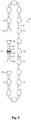
- balls 15 of a synthetic resin are molded at regular intervals on a cord 14 of polyester to form the ball chain 9.
- Each ball 15 is a solid body molded on a surface of the cord 14 to have a prolate spheroid shape by a molding machine, and each ball 15 is firmly fixed to the cord 14 so as to be immovable.
- the coupling portion 16 is composed of a first coupling member 17 and a second coupling member 18.
- a hemispheroid (half ball) 20 which is a little larger than a half of the ball 15 is formed by outsert molding onto an end of a coupling cord 19 made of a same material as that of the cord 14, and a first fitting part 21 is formed by outsert molding onto the other end such that the first fitting part 21 is solid as far as its front end.
- a space between the hemispheroid 20 and the first fitting part 21 is the same as the space between the balls 15.
- Fig. 4 illustrates a state where the coupling cord 19 is embedded to a neighborhood of the front end of the first fitting part 21. In this case, it is easy to ensure strength of the fitting protrusion 22 in a compression direction.
- the hemispheroid 20 and the first fitting part 21 are formed, of a same material as that of the ball 15, at the both ends of the coupling cord 19.
- a base end of the first fitting part 21 is formed into a hemispheroid similar to that of the end of the ball 15, and the fitting protrusion 22 of a round shank shape is formed at the front end of the first fitting part 21.
- the fitting protrusion 22 has a swelled portion 22a of a flange shape formed at a front end thereof, and an external shape of the swelled portion 22a has a diameter smaller than a maximum diameter of the hemispheroid-shaped base end. Further, a chamfered edge 22b is formed at a front end-side corner of the swelled portion 22a, so that the swelled portion 22a can be easily fitted into a fitting hole 26.
- the first fitting part 21 is molded integrally with the other end of the coupling cord 19. Further, the fitting protrusion 22 may be formed by molding in a similar way to that of the hemispheroid 20, followed by cutting.
- the second coupling member 18 has, as shown in Fig. 5 , a hemispheroid 24 having a shape of a half of the ball 15 formed at an end of a coupling cord 23 which is made of a same material as that of the cord 14, and a second fitting part 25 formed at the other end.
- a space between the hemispheroid 24 and the second fitting part 25 is the same as the space between the balls 15.
- the hemispheroid 24 and the second fitting part 25 are formed at both ends of the coupling cord 23 by means of outsert molding of a same material as that of the ball 15.
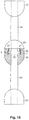
- a base end of the second fitting part 25 is formed into a hemispheroid shape similar to the end of the ball 15, and the fitting hole 26 is formed at a front end of the second fitting part 25. Further, a deep section of the fitting hole 26 is formed to have a diameter which is larger than a diameter of an opening portion thereof, so that, as shown in Fig. 6 , the deep section can fit resiliently with and hold the swelled portion 22a of the fitting protrusion 22.
- the fitting hole 26 is formed to have a depth that is equal to or smaller than a half of a length of the second fitting part 25, and the fitting protrusion 22 protrudes by a length that is equal to the depth of the fitting hole 26.
- a holding force of the fitting hole 26 to hold the fitting protrusion 22 is so set that the fitting of the fitting protrusion 22 and the fitting hole 26 is never broken with a normal pull force which is applied to the ball chain 9 during a usual operation to move the slats up or down as well as a usual operation to adjust an angle of the slats. Moreover, the fitting of the fitting protrusion 22 and the fitting hole 26 is broken due to resiliency of a synthetic resin, only when a great pull force that exceeds the normal pull force is applied to the ball chain 9.
- the fitting hole 26 is formed by forming, at the other end of the coupling cord 23, a hemispheroid similar to the hemispheroid 24, and hollowing out a front center of the hemispheroid by cutting. Further, the first and second fitting parts are so formed that, in a state where the fitting protrusion 22 is fitted in the fitting hole 26, as shown in Figs. 2 and 6 , an external shape of the first and second fitting parts is the same as that of the ball 15.
- the depth of the fitting hole 26 is set smaller than a half of the length of the second fitting part 25, and thus, the base end of the second fitting part 25 is a solid body. Accordingly, it is possible to ensure that the part of the coupling cord 23 which is embedded in the second fitting part 25 has a sufficient length.
- the hemispheroids 20, 24 of the first and second coupling members 17, 18 are fused to hemispheroids 15a formed at the both ends of the cord 14, forming balls of a same shape as that of the ball 15.
- the ball chain 9 of an endless type is obtained.
- balls having a same shape are formed at regular intervals along the entire length of the cord 14 of the ball chain 9 and the coupling cords 19, 23 of the coupling portion 16. Therefore, the ball chain 9 can be moved around unlimitedly relative to the pulley 8.
- the "operation cord” of the claims is a ball chain 9
- the "coupling portion” is composed of a first coupling member 27 and a second coupling member 28.
- the first coupling member 27 has a fitting protrusion 30 of a solid body.
- balls 15 of a synthetic resin are molded at regular intervals on a cord 14 of polyester to form the ball chain 9.
- Each ball 15 is a solid body molded on a surface of the cord 14 to have a prolate spheroid shape by a molding machine, and each ball 15 is firmly fixed to the cord 14 so as to be immovable.
- the coupling portion 16 is composed of a first coupling member 27 and a second coupling member 28.
- a hemispheroid 20 which has a shape of a half of the ball 15 is formed by outsert molding onto an end of a coupling cord 19 made of a same material as that of the cord 14, and a first fitting part 29 is formed at the other end.
- a space between the hemispheroid 20 and the first fitting part 29 is the same as the space between the balls 15.
- the hemispheroid 20 and the first fitting part 29 are formed, of a same synthetic resin as that of the ball 15, at the both ends of the coupling cord 19.
- a base end of the first fitting part 29 is formed into a hemispheroid similar to that of the end of the ball 15, and at a front end of the first fitting part 29 is formed a fitting protrusion 30 having a bale-shaped cross-section, which is obtained by cutting off both sides of a round shank along parallel lines.
- a swelled portion 31 being swelled in a long-axis direction of a bale shape is formed, and outer peripheral surfaces on both sides in the long-axis direction of the swelled portion 31 are provided with troughs 32 in an axis direction of the first fitting part 29. Further, a chamfered edge 33 is formed at a front end corner of the swelled portion 31.
- the second coupling member 28 has, as shown in Figs. 8 and 12 , a hemispheroid 24 having a shape of a half of the ball 15 formed at an end of a coupling cord 23 which is made of a same material as that of the cord 14, and a second fitting part 34 formed at the other end.
- the hemispheroid 24 and the second fitting part 34 are molded from a same synthetic resin as that of the ball 15, and a space between the hemispheroid 24 and the second fitting part 34 is the same as the space between the balls 15.
- the hemispheroid 24 and the second fitting part 34 are formed at both ends of the coupling cord 23 from a same material as that of the ball 15.
- a base end of the second fitting part 34 is formed into a hemispheroid shape similar to the end of the ball 15, and a fitting hole 35 is formed at a center of a front end surface of the second fitting part 34.
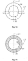
- the fitting hole 35 is opened, as shown in Fig. 13 , to have a bale shape in which the swelled portion 31 of the fitting protrusion 30 can be inserted.
- a deep section of the fitting hole 35 is formed, as shown in Figs. 12 and 14 , into a circular shape with a diameter which allows the fitting protrusion 30 to rotate within the fitting hole 35. Therefore, locking portions 37 are formed line-symmetrically which engage with the swelled portion 31 at an opening portion of the fitting portion 35. An opening edge of the locking portion 37 is gouged into an arc in order to allow a base portion of the fitting protrusion 30 to rotate.
- a ridge 36 which can engage with the trough 32 is formed on one side of an inner peripheral surface of the deep section of the fitting hole 35.
- the ridge 36 is formed on a short axis L2 which intersects with a long axis L1 of the opening of the fitting hole 35 at a right angle.
- the swelled portion 31 of the fitting protrusion 30 is inserted into the fitting hole 35 and subsequently rotated in either direction from this status.
- the trough 32 of the swelled portion 31 engages with the ridge 36 in the fitting hole 35 and is positioned, so that the swelled portion 31 is engaged with the locking portion 37 and held within the fitting hole 35.
- a holding force in this engagement is set such that the fitting of the fitting protrusion 30 and fitting hole 35 is never broken with a normal pull force applied to the ball chain 9 in a usual operation for moving up and down the slats and adjusting the angle of the slats.
- the first fitting part 29 and the second fitting part 34 are so configured that only when a great pull force that exceeds the normal pull force is applied to the ball chain 9, the opening portion of the fitting hole 35 is enlarged by the resiliency of the synthetic resin and thus the swelled portion 31 is pulled out of the fitting hole 35, whereby the fitting of the fitting protrusion 30 and the fitting hole 35 is broken.
- first and second fitting parts 29, 34 are formed to have, in a state where the fitting protrusion 30 is fitted with the fitting hole 35, an external shape that is the same as that of the ball 15.
- the hemispheroids 20, 24 of the first and second coupling members 27, 28 are fused to the hemispheroids 15a which are formed on the both ends of the cord 14 by means of outsert molding, to form balls each having the same shape as that of the ball 15.
- the ball chain 9 of an endless type is obtained.
- balls having a same shape are formed at regular intervals along the entire length of the cord 14 of the ball chain 9 and the coupling cords 19, 23 of the coupling portion 16. Therefore, the ball chain 9 can be moved around unlimitedly relative to the pulley 8.
- the first fitting part 29 and the second fitting part 34 may be formed of a material having rigidity larger than that of a synthetic resin. In this case, the failsafe function may not be obtained, but even when a great force is applied to the ball chain 9, it is not converted into a non-loop form, so that abrupt non-looping can be avoided.
- the "operation cord” of the claims is a ball chain 9
- the "coupling portion” is composed of two first coupling members 41 of a same structure and a second coupling member 42 of a tubular shape.
- the two first coupling members 41 are coupled to each other via the second coupling member 42.
- the first coupling member 41 has a fitting protrusion 45 of a solid body.
- balls 15 of a synthetic resin are molded at regular intervals on a cord 14 of polyester to form the ball chain 9.
- Each ball 15 is a solid body molded on a surface of the cord 14 to have a prolate spheroid shape by a molding machine, and each ball 15 is firmly fixed to the cord 14 so as to be immovable.
- Both ends of the cord 14 are coupled to each other by means of the coupling portion 16 to form the endless-type ball chain 9.
- the coupling portion 16 is configured such that the two first coupling members 41 of the same structure are coupled with each other via the second coupling member (second fitting part) 42.
- a hemispheroid 20 which has a shape of a half of the ball 15 is formed (outsert molding) onto an end of a coupling cord 19 made of a same material as that of the cord 14, and a first fitting part 43 is formed at the other end.
- a ball 44 having a same shape as that of the ball 15 is fixed between the hemispheroid 20 and the first fitting part 43, and a space between the first fitting part 43 and the ball 44 and a space between the ball 44 and the hemispheroid 20 are the same as the space between the balls 15.
- the hemispheroid 20 and the first fitting part 43 are formed, of a same synthetic resin as that of the ball 15, at the both ends of the coupling cord 19.
- a base end of the first fitting part 43 is formed into a hemispheroid similar to that of the end of the ball 15, and at the front end of the first fitting part 43 is formed (outsert molding) a fitting protrusion 45 of a round shank shape.
- swelled portions 46 are formed line-symmetrically with respect to a center of the round shank, and a trough 47 having a semicircular cross-section is formed at a center of each of the swelled portions 46. Further, chamfered edges 54 are formed at a front end side and a base end side of the swelled portion 46.
- rotation-restriction portions 48 protruding in radial directions of the round shank are formed line-symmetrically with respect to the center of the round shank. Further, each of the rotation-restriction portions 48 is formed at a position apart by 45 degrees in a circumferential direction from the trough 47 with respect to the center of the round shank.
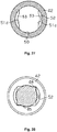
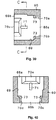
- the second coupling member 42 is formed, by molding a same synthetic resin as that of the first fitting part 43 and the balls 15, 44, into a tubular shape so as to be a second fitting part provided with a fitting hole, and configured, as shown in Figs. 23 and 24 , such that opening portions 49a, 49b at both sides thereof each have a bale shape into which the front end including the swelled portion 46 of the fitting protrusion 45 can be inserted. Further, the opening portions 49a, 49b are so shaped that directions of the bale shapes are mutually rotated by 90 degrees with respect to a center of the tube.
- a circular hole (fitting hole) 50 having a diameter which allows the front end of the fitting protrusion 45 to rotate is formed inside the second coupling member 42.
- locking portions 51a, 51b are formed, respectively, for preventing the swelled portion 46 from dropping out of the circular hole 50
- locking portions 51c, 51d are formed, respectively, for preventing the swelled portion 46 from dropping out of the circular hole 50.
- chamfered edges 53 are provided at boundary portions between the locking portions 51a-51d and the circular hole 50, so that the locking portions 51a-51d are not damaged when the fitting protrusion 45 is pulled out of the circular hole 50, due to working of the chamfered edges 53, 54.
- ridges 52 configured to engage with the troughs 47 are formed, respectively.
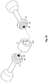
- the fitting protrusion 45 of the first fitting part 43 is inserted into one opening portion 49a, and the first fitting part 43 is rotated clockwise by 90 degrees relative to the second coupling member 42.
- the trough 47 of the swelled portion 45 engages with the ridge 52 in the circular hole 50, so that the rotation-restriction portion 48 moves from a corner portion of the bale shape of the opening portion 49a to a neighboring corner portion, where it is positioned.
- the fitting protrusion 45 of the first coupling member 41 is inserted into the other opening portion 49b of the second coupling member 42 and rotated by 90 degrees, to be positioned.
- the first coupling members 41 are coupled to each other via the second coupling member 42.
- a holding force in this engagement is set such that the fitting protrusion 45 is never disengaged from the second coupling member 42 with a normal pull force applied to the ball chain 9 in a usual operation for moving up and down the slats and adjusting the angle of the slats.
- the first and second coupling members are so configured that only when a great pull force that exceeds the normal pull force is applied to the ball chain 9, the opening portions 49a, 49b of the second coupling member 42 are enlarged due to resiliency of the synthetic resin of the second coupling member 42, and thus, the fitting protrusions 45 are uncoupled from the second coupling member 42.
- an external shape in a state where the first fitting parts 43 are fitted with the both sides of the second coupling member 42 is so designed as to be the same as that of the ball 15.
- the hemispheroid 20 of the first coupling member 41 is fused and fixed to the hemispheroid 15a outsert molded on the both ends of the cord 14, forming a ball of the same shape as that of the ball 15.
- balls having a same shape are formed at regular intervals along the entire length of the cord 14 of the ball chain 9 and the coupling cord 19 of the coupling portion 16. Therefore, the ball chain 9 can be moved around unlimitedly relative to the pulley 8.
- the first fitting part 43 and the second coupling member 42 may be formed of a material having a rigidity larger than that of a synthetic resin. In this case, the failsafe function may not be obtained, but even when a great force is applied to the ball chain 9, it is not converted into a non-loop form, so that abrupt non-looping can be avoided.
- the coupling portion 16 may be employed in an endless-type operation cord of an apparatus for shielding sunlight such as a vertical blind and a roller blind.
- the angle by which the first coupling member 41 is rotated relative to the second coupling member 42 when the first and second coupling members are fitted may be an angle other than 90 degrees.
- a swelled portion 46 may be formed around the entire circumference of the outer peripheral surface of the fitting protrusion 45 of the first fitting part 43, and the fitting protrusion 45 may be configured to fit with the opening portions 49a, 49b of the second coupling member 42.
- a step having a cross-section of a right angle may be provided in place of the chamfered edge 53 in the second coupling member 42.
- a junction surface between the hemispheroid 15a and the hemispheroids 20, 24 may be inclined with respect to axes of the hemispheroid 15a and the hemispheroids 20, 24, so that an area of the junction surface is increased.
- the coupling portion 16 may be provided at a middle portion of an operation cord hanging from a head box of a horizontal blind and connected to a bottom rail, to have a failsafe function.
- the "operation cord” of the claims is a ball chain 9
- the "coupling portion” is composed of two connector pieces 59a, 59b of a same structure and a coupling member 60 of a tubular shape.
- the two connector pieces 59a, 59b are coupled to each other via the coupling member 60.
- the connector pieces 59a, 59b each have a fitting protrusion 64 of a solid body.
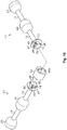
- the ball chain 55 shown in Fig. 30 has balls 57 of a synthetic resin which are molded at regular intervals on a cord 56 of polyester.
- Each ball 57 is a solid body molded on a surface of the cord 56 to have a prolate spheroid shape by a molding machine, and each ball 57 is firmly fixed to the cord 56 so as to be immovable.
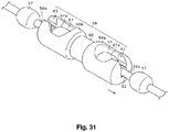
- Both ends of the cord 56 are coupled to each other by means of a connector 58 to form the endless-type ball chain 55.
- the connector 58 is configured such that the two connector pieces 59a, 59b of the same structure and the tubular coupling member 60 couple the balls 57a molded at both ends of the cord 56 with each other.
- the connector 58 connects the cord 56 to form the endless-type ball chain 55 and also acts, in a state where the ball chain 55 is in engagement with a pulley, as a stopper which abuts on the pulley and a pulley case so as to define an upper limit position of an operation for pulling up a shade or the like.
- the connector pieces 59a, 59b are formed to have external dimensions that cannot pass through a space between the pulley and the pulley case.
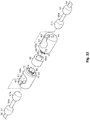
- connector piece 59a A specific structure of the connector piece 59a will be described with reference to Figs. 33 to 36 , since the connector pieces 59a, 59b have the same structure.
- the connector piece 59a is formed of a synthetic resin into a generally rectangular parallelepiped, and is provided, on a top surface thereof, with a locking hole 61 which is opened in an ellipse shape such that the ball 57a can be inserted.
- a locking hole 61 which is opened in an ellipse shape such that the ball 57a can be inserted.
- an insertion hole 62 is formed which continues to the locking hole 61, and the insertion hole 62 opens at the top surface of the connector piece 59a via a guide groove 63.
- a fitting protrusion 64 of a round shank shape is formed as a solid body protruding from the surface.
- swelled portions 65 are formed line-symmetrically with respect to a center of the round shank, and a trough 66 having a semicircular cross-section is formed at a center of each of the swelled portions 65.
- chamfered edges 72 are formed at a front end side and a base end side of the swelled portion 65.
- rotation-restriction portions 67 protruding in radial directions of the round shank are formed line-symmetrically with respect to the center. Moreover, each of the rotation-restriction portions 67 is formed at a position apart from the trough 66 by 45 degrees with respect to the center of the round shank.
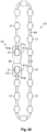
- the coupling member 60 is molded into a tubular shape from the same synthetic resin as that of the connector piece 59a, and, as shown in Figs. 37 and 38 , opening portions 68a, 68b on both sides are each formed into a bale shape into which the front end including the swelled portion 65 of the fitting protrusion 64 can be inserted. Further, the opening portions 68a, 68b are so formed that directions of their bale shapes are rotated from each other by 90 degrees with respect to a center of the tube.
- a circular hole 69 having a diameter which allows the front end of the fitting protrusion 64 to rotate is formed inside the coupling member 60.
- locking portions 70a, 70b are formed, respectively, for preventing the swelled portion 65 from dropping out of the circular hole 69, and at opening edges in the short-axis directions of the bale shape of the opening portion 68b, locking portions 70c, 70d are formed, respectively, for preventing the swelled portion 65 from dropping out of the circular hole 69.
- ridges 71 configured to engage with the troughs 66 are formed, respectively.
- the fitting protrusion 64 is inserted into one opening portion 68a, and the connector piece 59a is rotated clockwise by 90 degrees relative to the coupling member 60.
- the trough 66 of the fitting protrusion 64 engages with the ridge 71 in the circular hole 69, so that the rotation-restriction portion 67 moves from a corner portion of the bale shape of the opening portion 68a to a neighboring corner portion, where it is positioned, as shown in Fig. 42 .
- the fitting protrusion 64 of the connector piece 59b is inserted into the other opening portion 68b of the coupling member 60 and rotated by 90 degrees, to be positioned.
- the connector pieces 59a, 59b are coupled to each other via the coupling member 60, and the endless-type ball chain 55 is formed.
- a holding force in this engagement is set such that the fitting protrusion 64 is never disengaged from the coupling member 60 with a normal pull force applied to the ball chain 55 in a usual operation for moving up and down the slats and adjusting the angle of the slats.
- the connector pieces and the coupling member are so configured that only when a great pull force that exceeds the normal pull force is applied to the ball chain 55, the opening portions 68a, 68b of the coupling member 60 are enlarged, due to resiliency of the synthetic resin of the coupling member 60, by the swelled portions 65 of the fitting protrusions 64, and thus, the fitting protrusions 64 are uncoupled from the coupling member 60.
- chamfered edges 73 are provided at boundary portions between the locking portions 70a-70d and the circular hole 69, so that the locking portions 70a-70d are not damaged when the fitting protrusion 64 is pulled out of the circular hole 69, due to working of the chamfered edges 72, 73.
- a ball chain of an endless type of an apparatus for shielding sunlight such as a roller blind, a pleated curtain, and a tuck-up curtain may be formed.
- the connector 58 may be used as a connector for connecting, into an endless form, a ball chain for holding a name plate or the like hanging from the neck.
- the angle by which the connector pieces 59a, 59b are rotated relative to the coupling member 60 when the connector pieces 59a, 59b are fitted with the coupling member 60 may be an angle other than 90 degrees.
- the ball chain 55 may be a string-type cord which is provided with balls only at both ends thereof.
Landscapes
- Engineering & Computer Science (AREA)
- General Engineering & Computer Science (AREA)
- Structural Engineering (AREA)
- Mechanical Engineering (AREA)
- Architecture (AREA)
- Civil Engineering (AREA)
- Blinds (AREA)
- Pivots And Pivotal Connections (AREA)
- Ropes Or Cables (AREA)
- Toys (AREA)
Claims (15)
- Betätigungsschnur (9, 55), die eine Schnur (14, 56) umfasst, deren beide Enden mittels eines Kopplungsabschnitts (16, 58) gekoppelt sind, dadurch gekennzeichnet, dass
der Kopplungsabschnitt (16, 58) ein erstes Kopplungsteil (17, 27, 41, 59a, 59b) und ein zweites Kopplungsteil (18, 28) aufweist, die direkt oder über ein Kopplungselement (42, 60) miteinander gekoppelt sind,
eines der Kopplungsteile (17, 27, 41, 59a, 59b) oder das Kopplungselement (42, 60), einander benachbart, einen Passvorsprung (22, 30, 45, 64) aufweist und das andere der Kopplungsteile (18, 28) oder das Kopplungselement (42, 60), einander benachbart, ein Passloch (26, 35, 50, 69), das mit dem Passvorsprung (22, 30, 45, 64) zusammenpassbar ist, aufweist und
der Passvorsprung (22, 30, 45, 64) mit dem Passloch (26, 35, 50, 69) zusammenpassbar ist, indem er in das Passloch (26, 35, 50, 69) eingeführt und nachfolgend gedreht wird. - Betätigungsschnur (9, 55) nach Anspruch 1, wobei Kugeln (15, 57) aus einem Kunstharz geformt und in gleichmäßigen Abständen fest an der Schnur (14, 56) befestigt sind.
- Betätigungsschnur (9, 55) nach Anspruch 1 oder 2, wobei der Passvorsprung (22, 30, 45, 64) mit einem aufgeweiteten Abschnitt (22a, 31, 46, 65) versehen ist und das Passloch (26, 35, 50, 69) mit einem Verriegelungsabschnitt (37, 51a-d, 70a-d) versehen ist, der ausgestaltet ist, mit dem aufgeweiteten Abschnitt (22a, 31, 46, 65) in Eingriff zu stehen.
- Betätigungsschnur (9, 55) nach einem der Ansprüche 1 bis 3, wobei eine innere periphere Fläche des Passlochs (26, 35, 50, 69) mit Positionierungsmitteln (36, 52, 71) versehen ist, die ausgestaltet sind, den Passvorsprung (22, 30, 45, 64) im Zuge eines Drehens zu positionieren.
- Betätigungsschnur (9) nach einem der Ansprüche 1 bis 4, wobei
das erste Kopplungsteil (17, 27, 41, 59a, 59b) an einem Ende einer ersten Kopplungsschnur (19) ein erstes Passteil (21, 29, 43) aufweist, das mit dem Passvorsprung (22, 30, 45) versehen ist; und
das zweite Kopplungsteil (18, 28) an einem Ende einer zweiten Kopplungsschnur (23) ein zweites Passteil (25, 34, 43) aufweist, das mit dem Passvorsprung (22, 30, 45) oder dem Passloch (26, 35, 50) versehen ist,
wobei ein halbes Sphäroid (20, 24), das am anderen Ende jeder Kopplungsschnur (19, 23) vorgesehen ist, und ein halbes Sphäroid (15a), das an jedem Ende der Schnur (14) vorgesehen ist, miteinander verschmolzen sind, um die Kugel auszubilden. - Betätigungsschnur (9) nach Anspruch 5, wobei der Passvorsprung (22, 30, 45) mittels Outsert-Spritzgießen am Ende der ersten Kopplungsschnur (19) ausgebildet ist.
- Betätigungsschnur (9) nach Anspruch 5 oder 6, wobei das zweite Passteil (25, 34) mittels Outsert-Spritzgießen am Ende der zweiten Kopplungsschnur (23) ausgebildet ist, ein vorderes Ende des zweiten Passteils (25, 34) mit dem Passloch (26, 35) versehen ist und eine Tiefe des Passlochs (26, 35) gleich oder kleiner als eine(r) Hälfte einer Länge des zweiten Passteils (25, 34) ist.
- Betätigungsschnur (9, 55) nach einem der Ansprüche 1 bis 6, wobei
das erste und zweite Kopplungsteil (41, 59a, 59b) über das Kopplungselement (42, 60) miteinander gekoppelt sind;
das erste und zweite Kopplungsteil (41, 59a, 59b) jeweils mit einem axialen Passvorsprung (45, 64) versehen sind; und
das Kopplungselement (42, 60) röhrenförmig ist und an beiden Enden davon Passlöcher (50, 69) aufweist, um derart mit den Passvorsprüngen (45, 64) zusammenpassbar zu sein, dass die Passvorsprünge (45, 64) einander zugewandt sind. - Betätigungsschnur (55) nach einem der Ansprüche 1 bis 4, wobei
das erste und zweite Kopplungsteil (41, 59a, 59b) über das Kopplungselement (42, 60) miteinander gekoppelt sind;
das erste und zweite Kopplungsteil (41, 59a, 59b) ein Paar von Verbindungsstücken (59a, 59b) sind, die in der Lage sind, mit Kugeln (57a), die an den Enden der Schnur (56) angebracht sind, in Eingriff zu stehen, und axiale Passvorsprünge (64) aufweisen; und
das Kopplungselement (60) an beiden Enden davon Passlöcher (69) aufweist, um die Verbindungsstücke (59a, 59b) zu koppeln. - Betätigungsschnur (55) nach Anspruch 9, wobei das Paar von Verbindungsstücken (59a, 59b) eine gleiche Form aufweist.
- Betätigungsschnur (55) nach einem der Ansprüche 8 bis 10, wobei Passwinkel, mit denen ein Paar der Passvorsprünge (64) mit dem Kopplungselement (60) zusammenpasst, voneinander relativ versetzt sind.
- Herstellungsverfahren für eine Betätigungsschnur (9) nach einem der Ansprüche 1 bis 11, das folgende Schritte umfasst:Formen und festes Befestigen von Kugeln (15) aus einem Kunstharz an einer Schnur (14) in gleichmäßigen Abständen;Ausbilden eines ersten Passteils (21, 29, 43), das mit einem Passvorsprung (22, 30, 45) versehen ist, an einem Ende einer ersten Kopplungsschnur (19);Ausbilden eines halben Sphäroids (20), das einer Hälfte der Kugel (15) entspricht, am anderen Ende der ersten Kopplungsschnur (19);Ausbilden eines zweiten Passteils (25, 34), das mit einem Passloch (26, 35) versehen ist, an einem Ende einer zweiten Kopplungsschnur (23), wobei der Passvorsprung (22, 30) und das Passloch (26, 35) miteinander zusammenpassbar und voneinander entfernbar sind;Ausbilden eines halben Sphäroids (24), das einer Hälfte der Kugel (15) entspricht, am anderen Ende der zweiten Kopplungsschnur (23), wobei eine Form des ersten (21, 29) und zweiten Passteils (25, 34), wenn der Passvorsprung (22, 30) mit dem Passloch (26, 35) zusammengepasst ist, die gleiche ist wie diejenige der Kugel (15); undVerschmelzen der halben Sphäroide (20, 24) der ersten und zweiten Kopplungsschnur (19, 23) mit halben Sphäroiden (15a), die an beiden Enden der Schnur (14) ausgebildet sind, um die Kugeln (15) auszubilden.
- Kopplungselement (42, 60), das in der Betätigungsschnur (9, 55) nach einem der Ansprüche 1 bis 11 verwendbar ist, wobei das Kopplungselement (42, 60) einen Teil des Kopplungsabschnitts (16, 58) zum Koppeln beider Enden der Schnur (14, 56) durch Zusammenpassen des Passvorsprungs (45, 64) und des Passlochs (50, 69) bildet, dadurch gekennzeichnet, dass der Passvorsprung (45, 64) mit dem Passloch (50, 69) zusammenpassbar ist, indem er in das Passloch (50, 69) eingeführt und nachfolgend gedreht wird,
das Kopplungselement (42, 60) in einer Röhrenform ausgebildet ist, die an beiden Enden davon die Passlöcher (50, 69) aufweist,
ein kreisförmiges Loch (50, 69) innerhalb des Kopplungselements (42, 60) ausgebildet ist, wobei das kreisförmige Loch (50, 69) einen Durchmesser aufweist, der ein Drehen eines vorderen Endes des Passvorsprungs (45, 64) erlaubt, und
das Passloch (50, 69) an einem Teil einer inneren Peripherie davon mit einem Verriegelungsabschnitt (51a-d, 70a-d) versehen ist, der einen Durchmesser kleiner als derjenige des kreisförmigen Lochs aufweist. - Kopplungsteil (27, 41), das in der Betätigungsschnur (9) nach einem der Ansprüche 1 bis 8 verwendbar ist, wobei das Kopplungsteil (27, 41) einen Teil des Kopplungsabschnitts (16) zum Koppeln beider Enden der Schnur (9) durch Passen eines Passvorsprungs (30, 45) und eines Passlochs (35, 50) bildet, dadurch gekennzeichnet, dass der Passvorsprung (30, 45) mit dem Passloch (35, 50) zusammenpassbar ist, indem er in das Passloch (35, 50) eingeführt und nachfolgend gedreht wird,
das Kopplungsteil (27, 41) mit einem Basisendabschnitt versehen ist, der die Form eines halben Sphäroids aufweist, und wobei der Passvorsprung (30, 45) eine Rundstabform aufweist und von dem Basisendabschnitt hin zu einem vorderen Ende des Kopplungsteils (27, 41) vorsteht, und
ein Teil einer Peripherie eines vorderen Endabschnitts des Passvorsprungs (30, 45) mit einem aufgeweiteten Abschnitt (31, 46) versehen ist, dessen äußere periphere Form, vom vorderen Ende her gesehen, ein Bogen ist. - Verbindungsstück (59a, 59b), das in der Betätigungsschnur (55) nach einem der Ansprüche 9 bis 11 verwendbar ist, wobei das Verbindungsstück (59a, 59b) einen Teil eines Kopplungsabschnitts (58) zum Koppeln beider Enden der Schnur (56) durch Passen eines Passvorsprungs (64) und eines Passlochs (69) bildet, dadurch gekennzeichnet, dass der Passvorsprung (64) mit dem Passloch (69) zusammenpassbar ist, indem er in das Passloch (69) eingeführt und nachfolgend gedreht wird,
das Verbindungsstück (59a, 59b) in der Lage ist, mit einer Kugel (57a), die an einem Ende der Schnur (56) angebracht ist, in Eingriff zu stehen, und einen Passvorsprung (64) mit einer axialen Form aufweist, und
ein Teil einer Peripherie eines vorderen Endabschnitts des Passvorsprungs (64) mit einem aufgeweiteten Abschnitt (65) versehen ist, dessen äußere periphere Form, vom vorderen Ende her gesehen, ein Bogen ist.
Applications Claiming Priority (5)
| Application Number | Priority Date | Filing Date | Title |
|---|---|---|---|
| JP2009151568A JP5613387B2 (ja) | 2009-06-25 | 2009-06-25 | コード |
| JP2009151569A JP5439055B2 (ja) | 2009-06-25 | 2009-06-25 | コード |
| JP2009151567A JP5442331B2 (ja) | 2009-06-25 | 2009-06-25 | ボールチェーン及びボールチェーンの製造方法 |
| JP2009173385A JP5481121B2 (ja) | 2009-07-24 | 2009-07-24 | コードのコネクタ |
| PCT/JP2010/060611 WO2010150799A1 (ja) | 2009-06-25 | 2010-06-23 | 操作コード、操作コードの製造方法 |
Publications (3)
| Publication Number | Publication Date |
|---|---|
| EP2447568A1 EP2447568A1 (de) | 2012-05-02 |
| EP2447568A4 EP2447568A4 (de) | 2015-12-30 |
| EP2447568B1 true EP2447568B1 (de) | 2019-08-28 |
Family
ID=43386568
Family Applications (1)
| Application Number | Title | Priority Date | Filing Date |
|---|---|---|---|
| EP10792117.3A Active EP2447568B1 (de) | 2009-06-25 | 2010-06-23 | Betriebsstrang und herstellungsverfahren für betriebsstrang |
Country Status (6)
| Country | Link |
|---|---|
| EP (1) | EP2447568B1 (de) |
| KR (1) | KR101351241B1 (de) |
| CN (2) | CN104265142B (de) |
| AU (1) | AU2010263600B2 (de) |
| TW (1) | TWI500847B (de) |
| WO (1) | WO2010150799A1 (de) |
Families Citing this family (12)
| Publication number | Priority date | Publication date | Assignee | Title |
|---|---|---|---|---|
| CN102859107B (zh) * | 2010-04-30 | 2015-06-17 | 立川窗饰工业株式会社 | 操作拉绳,日照遮蔽装置的操作装置 |
| TWI527546B (zh) * | 2010-04-30 | 2016-04-01 | Tachikawa Blind Mfg | A manufacturing method of a ball chain, and a connecting member for a ball chain |
| JP2013145180A (ja) * | 2012-01-13 | 2013-07-25 | Olympus Corp | 放射線検出器,放射線検出装置及びそれらの動作方法 |
| KR200471337Y1 (ko) * | 2013-07-30 | 2014-02-20 | 김대영 | 롤 블라인드의 볼 체인용 안전연결고리 |
| CZ27693U1 (cs) * | 2014-08-26 | 2015-01-12 | Isotra A.S. | Spojka tažných orgánů, zejména kuličkových řetízků nebo šňůr pro ovládání pohonných mechanismů interiérových lamelových žaluzií |
| CN109534145B (zh) * | 2018-12-03 | 2020-08-07 | 东阳市中傲建筑工程有限公司 | 建材吊拉线 |
| WO2020136925A1 (ja) * | 2018-12-25 | 2020-07-02 | 立川ブラインド工業株式会社 | セーフティツール |
| US11306534B2 (en) | 2019-02-06 | 2022-04-19 | Hunter Douglas Inc. | Connector for a looped operating element of an architectural-structure covering |
| WO2020209355A1 (ja) * | 2019-04-12 | 2020-10-15 | 立川ブラインド工業株式会社 | ボールチェーンおよび遮蔽装置 |
| JP7502013B2 (ja) * | 2019-10-25 | 2024-06-18 | 立川ブラインド工業株式会社 | ボールチェーン |
| CN110671470B (zh) * | 2019-09-29 | 2021-03-05 | 梁恩 | 一种传动链 |
| JP7473458B2 (ja) * | 2020-11-17 | 2024-04-23 | Ykk Ap株式会社 | 引手部材 |
Family Cites Families (13)
| Publication number | Priority date | Publication date | Assignee | Title |
|---|---|---|---|---|
| JPS5023716Y1 (de) * | 1968-07-04 | 1975-07-17 | ||
| JPH05295642A (ja) * | 1992-04-09 | 1993-11-09 | Yoshida Kogyo Kk <Ykk> | 長尺ボールチェーンと継ぎ具 |
| JP2902267B2 (ja) * | 1993-06-03 | 1999-06-07 | 立川ブラインド工業株式会社 | 縦型ブラインド |
| CN1126275A (zh) * | 1995-01-06 | 1996-07-10 | 黄忠臣 | 窗帘拉绳双向脱开安全拉帽 |
| FR2789465B1 (fr) * | 1999-02-08 | 2001-03-23 | Zurfluh Feller | Dispositif de raboutage pour chainette de treuil a cordon |
| JP3945959B2 (ja) * | 2000-03-30 | 2007-07-18 | Ykk株式会社 | ボールチェーン用係着具 |
| US6250359B1 (en) * | 2000-06-06 | 2001-06-26 | Eric W. Lorio | Beaded chain for blinds |
| JP2003184456A (ja) * | 2001-12-20 | 2003-07-03 | Yokota:Kk | 日除け部材の操作コード |
| JP4438289B2 (ja) * | 2002-12-25 | 2010-03-24 | ブリヂストンフローテック株式会社 | 継手構造 |
| CN2620756Y (zh) * | 2003-03-26 | 2004-06-16 | 亿丰综合工业股份有限公司 | 具有拉绳安全挡止功能的百叶窗帘 |
| JP2007177440A (ja) | 2005-12-27 | 2007-07-12 | Tachikawa Blind Mfg Co Ltd | 操作コード接続具及び操作コード接続具の製造方法 |
| JP4832180B2 (ja) * | 2006-06-23 | 2011-12-07 | トーソー株式会社 | 日射遮蔽装置の操作コードの安全機構 |
| US7325279B2 (en) * | 2006-06-29 | 2008-02-05 | Tai-Long Huang | Cord-releasing safety device for window blind |
-
2010
- 2010-06-23 AU AU2010263600A patent/AU2010263600B2/en active Active
- 2010-06-23 CN CN201410384193.5A patent/CN104265142B/zh active Active
- 2010-06-23 CN CN201080027759.9A patent/CN102388236B/zh active Active
- 2010-06-23 KR KR1020127000924A patent/KR101351241B1/ko active Active
- 2010-06-23 EP EP10792117.3A patent/EP2447568B1/de active Active
- 2010-06-23 WO PCT/JP2010/060611 patent/WO2010150799A1/ja not_active Ceased
- 2010-06-24 TW TW099120567A patent/TWI500847B/zh not_active IP Right Cessation
Non-Patent Citations (1)
| Title |
|---|
| None * |
Also Published As
| Publication number | Publication date |
|---|---|
| EP2447568A4 (de) | 2015-12-30 |
| CN102388236A (zh) | 2012-03-21 |
| KR101351241B1 (ko) | 2014-01-13 |
| EP2447568A1 (de) | 2012-05-02 |
| KR20120024961A (ko) | 2012-03-14 |
| AU2010263600A1 (en) | 2012-02-16 |
| CN104265142A (zh) | 2015-01-07 |
| CN102388236B (zh) | 2014-09-03 |
| WO2010150799A1 (ja) | 2010-12-29 |
| AU2010263600B2 (en) | 2015-02-05 |
| TWI500847B (zh) | 2015-09-21 |
| TW201104059A (en) | 2011-02-01 |
| CN104265142B (zh) | 2016-05-11 |
Similar Documents
| Publication | Publication Date | Title |
|---|---|---|
| EP2447568B1 (de) | Betriebsstrang und herstellungsverfahren für betriebsstrang | |
| US8898871B2 (en) | Operation cord, and operation apparatus for sunlight shielding apparatus | |
| JP5341637B2 (ja) | 操作コード | |
| JP5514494B2 (ja) | 操作コードおよびそれを用いた昇降装置 | |
| JP5719120B2 (ja) | 操作コード | |
| EP2565494A1 (de) | Herstellungsverfahren für perlenketten und verbindungselement für perlenketten | |
| EP2474701B1 (de) | Betriebsseil und hebevorrichtung damit | |
| JP5538599B2 (ja) | 無端コード | |
| JP5613387B2 (ja) | コード | |
| JP2011006928A (ja) | ボールチェーン及び横型ブラインドのコード | |
| JP5442331B2 (ja) | ボールチェーン及びボールチェーンの製造方法 | |
| JP5351349B2 (ja) | 操作コードおよびそれを用いた昇降装置 | |
| JP5610833B2 (ja) | 操作コードの製造方法、操作コードの連結部材 | |
| JP2011236555A (ja) | 操作コード | |
| JP3650017B2 (ja) | ブラインド巻取装置 | |
| JP5752777B2 (ja) | ボールチェーン及びブラインド | |
| JP5767363B2 (ja) | 操作コード及び操作コードにより操作されるブラインド |
Legal Events
| Date | Code | Title | Description |
|---|---|---|---|
| PUAI | Public reference made under article 153(3) epc to a published international application that has entered the european phase |
Free format text: ORIGINAL CODE: 0009012 |
|
| 17P | Request for examination filed |
Effective date: 20120119 |
|
| AK | Designated contracting states |
Kind code of ref document: A1 Designated state(s): AL AT BE BG CH CY CZ DE DK EE ES FI FR GB GR HR HU IE IS IT LI LT LU LV MC MK MT NL NO PL PT RO SE SI SK SM TR |
|
| DAX | Request for extension of the european patent (deleted) | ||
| RA4 | Supplementary search report drawn up and despatched (corrected) |
Effective date: 20151130 |
|
| RIC1 | Information provided on ipc code assigned before grant |
Ipc: F16G 11/00 20060101AFI20151124BHEP Ipc: E06B 9/326 20060101ALI20151124BHEP Ipc: F16B 21/04 20060101ALI20151124BHEP Ipc: F16G 13/12 20060101ALI20151124BHEP |
|
| STAA | Information on the status of an ep patent application or granted ep patent |
Free format text: STATUS: EXAMINATION IS IN PROGRESS |
|
| 17Q | First examination report despatched |
Effective date: 20171208 |
|
| GRAP | Despatch of communication of intention to grant a patent |
Free format text: ORIGINAL CODE: EPIDOSNIGR1 |
|
| STAA | Information on the status of an ep patent application or granted ep patent |
Free format text: STATUS: GRANT OF PATENT IS INTENDED |
|
| INTG | Intention to grant announced |
Effective date: 20190320 |
|
| RIN1 | Information on inventor provided before grant (corrected) |
Inventor name: NAKAMURA, HAJIME Inventor name: KAWAI, EIJI Inventor name: YAMAGUCHI, MASAYA |
|
| GRAS | Grant fee paid |
Free format text: ORIGINAL CODE: EPIDOSNIGR3 |
|
| GRAA | (expected) grant |
Free format text: ORIGINAL CODE: 0009210 |
|
| STAA | Information on the status of an ep patent application or granted ep patent |
Free format text: STATUS: THE PATENT HAS BEEN GRANTED |
|
| AK | Designated contracting states |
Kind code of ref document: B1 Designated state(s): AL AT BE BG CH CY CZ DE DK EE ES FI FR GB GR HR HU IE IS IT LI LT LU LV MC MK MT NL NO PL PT RO SE SI SK SM TR |
|
| REG | Reference to a national code |
Ref country code: GB Ref legal event code: FG4D |
|
| REG | Reference to a national code |
Ref country code: CH Ref legal event code: EP |
|
| REG | Reference to a national code |
Ref country code: DE Ref legal event code: R096 Ref document number: 602010060796 Country of ref document: DE |
|
| REG | Reference to a national code |
Ref country code: AT Ref legal event code: REF Ref document number: 1172804 Country of ref document: AT Kind code of ref document: T Effective date: 20190915 |
|
| REG | Reference to a national code |
Ref country code: IE Ref legal event code: FG4D |
|
| REG | Reference to a national code |
Ref country code: NL Ref legal event code: MP Effective date: 20190828 |
|
| REG | Reference to a national code |
Ref country code: LT Ref legal event code: MG4D |
|
| PG25 | Lapsed in a contracting state [announced via postgrant information from national office to epo] |
Ref country code: NO Free format text: LAPSE BECAUSE OF FAILURE TO SUBMIT A TRANSLATION OF THE DESCRIPTION OR TO PAY THE FEE WITHIN THE PRESCRIBED TIME-LIMIT Effective date: 20191128 Ref country code: BG Free format text: LAPSE BECAUSE OF FAILURE TO SUBMIT A TRANSLATION OF THE DESCRIPTION OR TO PAY THE FEE WITHIN THE PRESCRIBED TIME-LIMIT Effective date: 20191128 Ref country code: HR Free format text: LAPSE BECAUSE OF FAILURE TO SUBMIT A TRANSLATION OF THE DESCRIPTION OR TO PAY THE FEE WITHIN THE PRESCRIBED TIME-LIMIT Effective date: 20190828 Ref country code: LT Free format text: LAPSE BECAUSE OF FAILURE TO SUBMIT A TRANSLATION OF THE DESCRIPTION OR TO PAY THE FEE WITHIN THE PRESCRIBED TIME-LIMIT Effective date: 20190828 Ref country code: NL Free format text: LAPSE BECAUSE OF FAILURE TO SUBMIT A TRANSLATION OF THE DESCRIPTION OR TO PAY THE FEE WITHIN THE PRESCRIBED TIME-LIMIT Effective date: 20190828 Ref country code: PT Free format text: LAPSE BECAUSE OF FAILURE TO SUBMIT A TRANSLATION OF THE DESCRIPTION OR TO PAY THE FEE WITHIN THE PRESCRIBED TIME-LIMIT Effective date: 20191230 Ref country code: FI Free format text: LAPSE BECAUSE OF FAILURE TO SUBMIT A TRANSLATION OF THE DESCRIPTION OR TO PAY THE FEE WITHIN THE PRESCRIBED TIME-LIMIT Effective date: 20190828 Ref country code: SE Free format text: LAPSE BECAUSE OF FAILURE TO SUBMIT A TRANSLATION OF THE DESCRIPTION OR TO PAY THE FEE WITHIN THE PRESCRIBED TIME-LIMIT Effective date: 20190828 |
|
| PG25 | Lapsed in a contracting state [announced via postgrant information from national office to epo] |
Ref country code: AL Free format text: LAPSE BECAUSE OF FAILURE TO SUBMIT A TRANSLATION OF THE DESCRIPTION OR TO PAY THE FEE WITHIN THE PRESCRIBED TIME-LIMIT Effective date: 20190828 Ref country code: GR Free format text: LAPSE BECAUSE OF FAILURE TO SUBMIT A TRANSLATION OF THE DESCRIPTION OR TO PAY THE FEE WITHIN THE PRESCRIBED TIME-LIMIT Effective date: 20191129 Ref country code: IS Free format text: LAPSE BECAUSE OF FAILURE TO SUBMIT A TRANSLATION OF THE DESCRIPTION OR TO PAY THE FEE WITHIN THE PRESCRIBED TIME-LIMIT Effective date: 20191228 Ref country code: LV Free format text: LAPSE BECAUSE OF FAILURE TO SUBMIT A TRANSLATION OF THE DESCRIPTION OR TO PAY THE FEE WITHIN THE PRESCRIBED TIME-LIMIT Effective date: 20190828 Ref country code: ES Free format text: LAPSE BECAUSE OF FAILURE TO SUBMIT A TRANSLATION OF THE DESCRIPTION OR TO PAY THE FEE WITHIN THE PRESCRIBED TIME-LIMIT Effective date: 20190828 |
|
| REG | Reference to a national code |
Ref country code: AT Ref legal event code: MK05 Ref document number: 1172804 Country of ref document: AT Kind code of ref document: T Effective date: 20190828 |
|
| PG25 | Lapsed in a contracting state [announced via postgrant information from national office to epo] |
Ref country code: TR Free format text: LAPSE BECAUSE OF FAILURE TO SUBMIT A TRANSLATION OF THE DESCRIPTION OR TO PAY THE FEE WITHIN THE PRESCRIBED TIME-LIMIT Effective date: 20190828 |
|
| PG25 | Lapsed in a contracting state [announced via postgrant information from national office to epo] |
Ref country code: IT Free format text: LAPSE BECAUSE OF FAILURE TO SUBMIT A TRANSLATION OF THE DESCRIPTION OR TO PAY THE FEE WITHIN THE PRESCRIBED TIME-LIMIT Effective date: 20190828 Ref country code: RO Free format text: LAPSE BECAUSE OF FAILURE TO SUBMIT A TRANSLATION OF THE DESCRIPTION OR TO PAY THE FEE WITHIN THE PRESCRIBED TIME-LIMIT Effective date: 20190828 Ref country code: EE Free format text: LAPSE BECAUSE OF FAILURE TO SUBMIT A TRANSLATION OF THE DESCRIPTION OR TO PAY THE FEE WITHIN THE PRESCRIBED TIME-LIMIT Effective date: 20190828 Ref country code: DK Free format text: LAPSE BECAUSE OF FAILURE TO SUBMIT A TRANSLATION OF THE DESCRIPTION OR TO PAY THE FEE WITHIN THE PRESCRIBED TIME-LIMIT Effective date: 20190828 Ref country code: AT Free format text: LAPSE BECAUSE OF FAILURE TO SUBMIT A TRANSLATION OF THE DESCRIPTION OR TO PAY THE FEE WITHIN THE PRESCRIBED TIME-LIMIT Effective date: 20190828 Ref country code: PL Free format text: LAPSE BECAUSE OF FAILURE TO SUBMIT A TRANSLATION OF THE DESCRIPTION OR TO PAY THE FEE WITHIN THE PRESCRIBED TIME-LIMIT Effective date: 20190828 |
|
| PG25 | Lapsed in a contracting state [announced via postgrant information from national office to epo] |
Ref country code: CZ Free format text: LAPSE BECAUSE OF FAILURE TO SUBMIT A TRANSLATION OF THE DESCRIPTION OR TO PAY THE FEE WITHIN THE PRESCRIBED TIME-LIMIT Effective date: 20190828 Ref country code: SK Free format text: LAPSE BECAUSE OF FAILURE TO SUBMIT A TRANSLATION OF THE DESCRIPTION OR TO PAY THE FEE WITHIN THE PRESCRIBED TIME-LIMIT Effective date: 20190828 Ref country code: IS Free format text: LAPSE BECAUSE OF FAILURE TO SUBMIT A TRANSLATION OF THE DESCRIPTION OR TO PAY THE FEE WITHIN THE PRESCRIBED TIME-LIMIT Effective date: 20200224 Ref country code: SM Free format text: LAPSE BECAUSE OF FAILURE TO SUBMIT A TRANSLATION OF THE DESCRIPTION OR TO PAY THE FEE WITHIN THE PRESCRIBED TIME-LIMIT Effective date: 20190828 |
|
| REG | Reference to a national code |
Ref country code: DE Ref legal event code: R097 Ref document number: 602010060796 Country of ref document: DE |
|
| PLBE | No opposition filed within time limit |
Free format text: ORIGINAL CODE: 0009261 |
|
| STAA | Information on the status of an ep patent application or granted ep patent |
Free format text: STATUS: NO OPPOSITION FILED WITHIN TIME LIMIT |
|
| PG2D | Information on lapse in contracting state deleted |
Ref country code: IS |
|
| 26N | No opposition filed |
Effective date: 20200603 |
|
| PG25 | Lapsed in a contracting state [announced via postgrant information from national office to epo] |
Ref country code: SI Free format text: LAPSE BECAUSE OF FAILURE TO SUBMIT A TRANSLATION OF THE DESCRIPTION OR TO PAY THE FEE WITHIN THE PRESCRIBED TIME-LIMIT Effective date: 20190828 |
|
| PG25 | Lapsed in a contracting state [announced via postgrant information from national office to epo] |
Ref country code: MC Free format text: LAPSE BECAUSE OF FAILURE TO SUBMIT A TRANSLATION OF THE DESCRIPTION OR TO PAY THE FEE WITHIN THE PRESCRIBED TIME-LIMIT Effective date: 20190828 |
|
| REG | Reference to a national code |
Ref country code: CH Ref legal event code: PL |
|
| PG25 | Lapsed in a contracting state [announced via postgrant information from national office to epo] |
Ref country code: LU Free format text: LAPSE BECAUSE OF NON-PAYMENT OF DUE FEES Effective date: 20200623 |
|
| REG | Reference to a national code |
Ref country code: BE Ref legal event code: MM Effective date: 20200630 |
|
| PG25 | Lapsed in a contracting state [announced via postgrant information from national office to epo] |
Ref country code: IE Free format text: LAPSE BECAUSE OF NON-PAYMENT OF DUE FEES Effective date: 20200623 Ref country code: LI Free format text: LAPSE BECAUSE OF NON-PAYMENT OF DUE FEES Effective date: 20200630 Ref country code: CH Free format text: LAPSE BECAUSE OF NON-PAYMENT OF DUE FEES Effective date: 20200630 |
|
| PG25 | Lapsed in a contracting state [announced via postgrant information from national office to epo] |
Ref country code: BE Free format text: LAPSE BECAUSE OF NON-PAYMENT OF DUE FEES Effective date: 20200630 |
|
| PGFP | Annual fee paid to national office [announced via postgrant information from national office to epo] |
Ref country code: DE Payment date: 20210629 Year of fee payment: 12 Ref country code: FR Payment date: 20210621 Year of fee payment: 12 |
|
| PGFP | Annual fee paid to national office [announced via postgrant information from national office to epo] |
Ref country code: GB Payment date: 20210623 Year of fee payment: 12 |
|
| PG25 | Lapsed in a contracting state [announced via postgrant information from national office to epo] |
Ref country code: MT Free format text: LAPSE BECAUSE OF FAILURE TO SUBMIT A TRANSLATION OF THE DESCRIPTION OR TO PAY THE FEE WITHIN THE PRESCRIBED TIME-LIMIT Effective date: 20190828 Ref country code: CY Free format text: LAPSE BECAUSE OF FAILURE TO SUBMIT A TRANSLATION OF THE DESCRIPTION OR TO PAY THE FEE WITHIN THE PRESCRIBED TIME-LIMIT Effective date: 20190828 |
|
| PG25 | Lapsed in a contracting state [announced via postgrant information from national office to epo] |
Ref country code: MK Free format text: LAPSE BECAUSE OF FAILURE TO SUBMIT A TRANSLATION OF THE DESCRIPTION OR TO PAY THE FEE WITHIN THE PRESCRIBED TIME-LIMIT Effective date: 20190828 |
|
| REG | Reference to a national code |
Ref country code: DE Ref legal event code: R119 Ref document number: 602010060796 Country of ref document: DE |
|
| GBPC | Gb: european patent ceased through non-payment of renewal fee |
Effective date: 20220623 |
|
| PG25 | Lapsed in a contracting state [announced via postgrant information from national office to epo] |
Ref country code: FR Free format text: LAPSE BECAUSE OF NON-PAYMENT OF DUE FEES Effective date: 20220630 |
|
| PG25 | Lapsed in a contracting state [announced via postgrant information from national office to epo] |
Ref country code: GB Free format text: LAPSE BECAUSE OF NON-PAYMENT OF DUE FEES Effective date: 20220623 Ref country code: DE Free format text: LAPSE BECAUSE OF NON-PAYMENT OF DUE FEES Effective date: 20230103 |