EP2447708A1 - Détection de fissure à l'aide d'un prétraitement cryotechnique - Google Patents
Détection de fissure à l'aide d'un prétraitement cryotechnique Download PDFInfo
- Publication number
- EP2447708A1 EP2447708A1 EP10189665A EP10189665A EP2447708A1 EP 2447708 A1 EP2447708 A1 EP 2447708A1 EP 10189665 A EP10189665 A EP 10189665A EP 10189665 A EP10189665 A EP 10189665A EP 2447708 A1 EP2447708 A1 EP 2447708A1
- Authority
- EP
- European Patent Office
- Prior art keywords
- component
- crack
- turbine
- blade
- combustion chamber
- Prior art date
- Legal status (The legal status is an assumption and is not a legal conclusion. Google has not performed a legal analysis and makes no representation as to the accuracy of the status listed.)
- Withdrawn
Links
- 238000001514 detection method Methods 0.000 title claims description 4
- 238000002203 pretreatment Methods 0.000 title 1
- 238000000034 method Methods 0.000 claims abstract description 19
- 239000007789 gas Substances 0.000 claims description 18
- 239000007788 liquid Substances 0.000 claims description 14
- 230000035515 penetration Effects 0.000 claims description 10
- 238000001816 cooling Methods 0.000 claims description 8
- CURLTUGMZLYLDI-UHFFFAOYSA-N Carbon dioxide Chemical compound O=C=O CURLTUGMZLYLDI-UHFFFAOYSA-N 0.000 claims description 4
- 239000003086 colorant Substances 0.000 claims description 3
- 230000035939 shock Effects 0.000 claims description 3
- IJGRMHOSHXDMSA-UHFFFAOYSA-N Atomic nitrogen Chemical compound N#N IJGRMHOSHXDMSA-UHFFFAOYSA-N 0.000 claims description 2
- 239000001569 carbon dioxide Substances 0.000 claims description 2
- 229910002092 carbon dioxide Inorganic materials 0.000 claims description 2
- -1 In particular Substances 0.000 claims 1
- 239000004078 cryogenic material Substances 0.000 claims 1
- 239000007850 fluorescent dye Substances 0.000 claims 1
- 239000000463 material Substances 0.000 abstract description 11
- 238000000926 separation method Methods 0.000 abstract description 5
- 238000005382 thermal cycling Methods 0.000 abstract description 2
- 238000002485 combustion reaction Methods 0.000 description 16
- 239000010410 layer Substances 0.000 description 12
- PXHVJJICTQNCMI-UHFFFAOYSA-N Nickel Chemical compound [Ni] PXHVJJICTQNCMI-UHFFFAOYSA-N 0.000 description 11
- 239000012720 thermal barrier coating Substances 0.000 description 10
- 238000000576 coating method Methods 0.000 description 8
- 229910017052 cobalt Inorganic materials 0.000 description 5
- 239000010941 cobalt Substances 0.000 description 5
- GUTLYIVDDKVIGB-UHFFFAOYSA-N cobalt atom Chemical compound [Co] GUTLYIVDDKVIGB-UHFFFAOYSA-N 0.000 description 5
- 239000013078 crystal Substances 0.000 description 5
- 229910000601 superalloy Inorganic materials 0.000 description 5
- 229910045601 alloy Inorganic materials 0.000 description 4
- 239000000956 alloy Substances 0.000 description 4
- 238000005260 corrosion Methods 0.000 description 4
- 229910052759 nickel Inorganic materials 0.000 description 4
- 239000000758 substrate Substances 0.000 description 4
- XEEYBQQBJWHFJM-UHFFFAOYSA-N Iron Chemical compound [Fe] XEEYBQQBJWHFJM-UHFFFAOYSA-N 0.000 description 3
- 238000000137 annealing Methods 0.000 description 3
- BRPQOXSCLDDYGP-UHFFFAOYSA-N calcium oxide Chemical compound [O-2].[Ca+2] BRPQOXSCLDDYGP-UHFFFAOYSA-N 0.000 description 3
- 239000000292 calcium oxide Substances 0.000 description 3
- ODINCKMPIJJUCX-UHFFFAOYSA-N calcium oxide Inorganic materials [Ca]=O ODINCKMPIJJUCX-UHFFFAOYSA-N 0.000 description 3
- 230000007797 corrosion Effects 0.000 description 3
- 238000005566 electron beam evaporation Methods 0.000 description 3
- 229910052735 hafnium Inorganic materials 0.000 description 3
- VBJZVLUMGGDVMO-UHFFFAOYSA-N hafnium atom Chemical compound [Hf] VBJZVLUMGGDVMO-UHFFFAOYSA-N 0.000 description 3
- 239000000395 magnesium oxide Substances 0.000 description 3
- CPLXHLVBOLITMK-UHFFFAOYSA-N magnesium oxide Inorganic materials [Mg]=O CPLXHLVBOLITMK-UHFFFAOYSA-N 0.000 description 3
- AXZKOIWUVFPNLO-UHFFFAOYSA-N magnesium;oxygen(2-) Chemical compound [O-2].[Mg+2] AXZKOIWUVFPNLO-UHFFFAOYSA-N 0.000 description 3
- 230000003647 oxidation Effects 0.000 description 3
- 238000007254 oxidation reaction Methods 0.000 description 3
- 238000005554 pickling Methods 0.000 description 3
- 239000011241 protective layer Substances 0.000 description 3
- 229910052710 silicon Inorganic materials 0.000 description 3
- 239000010703 silicon Substances 0.000 description 3
- 239000007787 solid Substances 0.000 description 3
- 238000007711 solidification Methods 0.000 description 3
- 230000008023 solidification Effects 0.000 description 3
- 229910052727 yttrium Inorganic materials 0.000 description 3
- VWQVUPCCIRVNHF-UHFFFAOYSA-N yttrium atom Chemical compound [Y] VWQVUPCCIRVNHF-UHFFFAOYSA-N 0.000 description 3
- RUDFQVOCFDJEEF-UHFFFAOYSA-N yttrium(III) oxide Inorganic materials [O-2].[O-2].[O-2].[Y+3].[Y+3] RUDFQVOCFDJEEF-UHFFFAOYSA-N 0.000 description 3
- 238000005266 casting Methods 0.000 description 2
- 239000000919 ceramic Substances 0.000 description 2
- 239000000203 mixture Substances 0.000 description 2
- 238000007750 plasma spraying Methods 0.000 description 2
- 238000009419 refurbishment Methods 0.000 description 2
- 238000005488 sandblasting Methods 0.000 description 2
- YPFNIPKMNMDDDB-UHFFFAOYSA-K 2-[2-[bis(carboxylatomethyl)amino]ethyl-(2-hydroxyethyl)amino]acetate;iron(3+) Chemical compound [Fe+3].OCCN(CC([O-])=O)CCN(CC([O-])=O)CC([O-])=O YPFNIPKMNMDDDB-UHFFFAOYSA-K 0.000 description 1
- 241000191291 Abies alba Species 0.000 description 1
- 239000008186 active pharmaceutical agent Substances 0.000 description 1
- 238000009835 boiling Methods 0.000 description 1
- 238000005524 ceramic coating Methods 0.000 description 1
- 238000004140 cleaning Methods 0.000 description 1
- 239000011248 coating agent Substances 0.000 description 1
- 239000002826 coolant Substances 0.000 description 1
- 230000001419 dependent effect Effects 0.000 description 1
- 238000001704 evaporation Methods 0.000 description 1
- 239000012530 fluid Substances 0.000 description 1
- 238000005242 forging Methods 0.000 description 1
- 239000000446 fuel Substances 0.000 description 1
- 230000017525 heat dissipation Effects 0.000 description 1
- 238000007654 immersion Methods 0.000 description 1
- 238000004519 manufacturing process Methods 0.000 description 1
- 239000000155 melt Substances 0.000 description 1
- 229910001092 metal group alloy Inorganic materials 0.000 description 1
- 239000007769 metal material Substances 0.000 description 1
- 238000003801 milling Methods 0.000 description 1
- TWNQGVIAIRXVLR-UHFFFAOYSA-N oxo(oxoalumanyloxy)alumane Chemical compound O=[Al]O[Al]=O TWNQGVIAIRXVLR-UHFFFAOYSA-N 0.000 description 1
- 230000000149 penetrating effect Effects 0.000 description 1
- 238000010248 power generation Methods 0.000 description 1
- 239000011253 protective coating Substances 0.000 description 1
- 230000001681 protective effect Effects 0.000 description 1
- 229910052761 rare earth metal Inorganic materials 0.000 description 1
- 150000002910 rare earth metals Chemical class 0.000 description 1
- 229910052706 scandium Inorganic materials 0.000 description 1
- SIXSYDAISGFNSX-UHFFFAOYSA-N scandium atom Chemical compound [Sc] SIXSYDAISGFNSX-UHFFFAOYSA-N 0.000 description 1
- 230000035882 stress Effects 0.000 description 1
- 239000000126 substance Substances 0.000 description 1
- 230000008646 thermal stress Effects 0.000 description 1
- 230000001052 transient effect Effects 0.000 description 1
- 230000007704 transition Effects 0.000 description 1
Images


Classifications
-
- G—PHYSICS
- G01—MEASURING; TESTING
- G01N—INVESTIGATING OR ANALYSING MATERIALS BY DETERMINING THEIR CHEMICAL OR PHYSICAL PROPERTIES
- G01N21/00—Investigating or analysing materials by the use of optical means, i.e. using sub-millimetre waves, infrared, visible or ultraviolet light
- G01N21/84—Systems specially adapted for particular applications
- G01N21/88—Investigating the presence of flaws or contamination
- G01N21/91—Investigating the presence of flaws or contamination using penetration of dyes, e.g. fluorescent ink
Definitions
- the invention relates to the cryogenic pretreatment of a component in order to better detect cracks.
- the object is achieved by a method according to claim 1.
- the substrate 4 is cooled at least locally. This is preferably done by cryogenic media.
- the cooling is preferably also shock-like.
- a component 4 with a material separation 10 which is difficult to detect is introduced into a container 11 with a cryogenic liquid.
- the component 4 is then kept in the liquid for a certain time and then removed again and then supplied to the penetration test, in particular dye penetration test.
- the cryogenic process is performed in a fraction of the time required for conventional thermal cycling or pickling.
- the devices, or the material for carrying out cryogenic processes, are comparatively inexpensive.
- the surface is additionally cleaned, so that the component 4, 120, 130 can be used directly for the subsequent dye penetration test without repeated prior cleaning.
- FIG. 3 shows a perspective view of a blade 120 or guide vane 130 of a turbomachine, which extends along a longitudinal axis 121.
- the turbomachine may be a gas turbine of an aircraft or a power plant for power generation, a steam turbine or a compressor.
- the blade 120, 130 has along the longitudinal axis 121 consecutively a fastening region 400, a blade platform 403 adjacent thereto and an airfoil 406 and a blade tip 415.
- the blade 130 may have at its blade tip 415 another platform (not shown).
- a blade root 183 is formed, which serves for attachment of the blades 120, 130 to a shaft or a disc (not shown).
- the blade 120, 130 has a leading edge 409 and a trailing edge 412 for a medium flowing past the airfoil 406.
- the blade 120, 130 can be made by a casting process, also by directional solidification, by a forging process, by a milling process or combinations thereof.
- Workpieces with a monocrystalline structure or structures are used as components for machines which are exposed to high mechanical, thermal and / or chemical stresses during operation.
- directionally solidified microstructures which means both single crystals that have no grain boundaries or at most small angle grain boundaries, and stem crystal structures that have probably longitudinal grain boundaries but no transverse grain boundaries. These second-mentioned crystalline structures are also known as directionally solidified structures.
- the blades 120, 130 may have coatings against corrosion or oxidation, e.g. M is at least one element of the group iron (Fe), cobalt (Co), nickel (Ni), X is an active element and stands for yttrium (Y) and / or silicon and / or at least one element of the rare ones Earth, or hafnium (Hf)).
- M is at least one element of the group iron (Fe), cobalt (Co), nickel (Ni)
- X is an active element and stands for yttrium (Y) and / or silicon and / or at least one element of the rare ones Earth, or hafnium (Hf)).
- Such alloys are known from the EP 0 486 489 B1 .
- EP 0 412 397 B1 or EP 1 306 454 A1 are known from the EP 0 486 489 B1 .
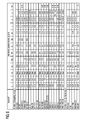
- the layer composition comprises Co-30Ni-28Cr-8Al-0.6Y-0.7Si or Co-28Ni-24Cr-10Al-0.6Y.
- nickel-based protective layers such as Ni-10Cr-12Al-0,6Y-3Re or Ni-12Co-21Cr-11A1-0,4Y-2Re or Ni-25Co-17Cr-10Al-0,4Y-1 are also preferably used , 5RE.
- thermal barrier coating which is preferably the outermost layer, and consists for example of ZrO 2 , Y 2 O 3 -ZrO 2 , ie it is not, partially or completely stabilized by yttria and / or calcium oxide and / or magnesium oxide.
- the thermal barrier coating covers the entire MCrAlX layer.
- suitable coating methods e.g. Electron beam evaporation (EB-PVD) produces stalk-shaped grains in the thermal barrier coating.
- the thermal barrier coating may have porous, micro- or macro-cracked grains for better thermal shock resistance.
- the thermal barrier coating is therefore preferably more porous than the MCrAlX layer.
- Refurbishment means that components 120, 130 may need to be deprotected after use (e.g., by sandblasting). This is followed by removal of the corrosion and / or oxidation layers or products. Optionally, even cracks in the component 120, 130 are repaired. This is followed by a re-coating of the component 120, 130 and a renewed use of the component 120, 130.
- the blade 120, 130 may be hollow or solid. If the blade 120, 130 is to be cooled, it is hollow and may still film cooling holes 418 (indicated by dashed lines) on.
- FIG. 4 shows a combustion chamber 110 of a gas turbine.
- the combustion chamber 110 is designed, for example, as a so-called annular combustion chamber, in which a plurality of burners 107 arranged around a rotation axis 102 in the circumferential direction open into a common combustion chamber space 154, which generate flames 156.
- the combustion chamber 110 is configured in its entirety as an annular structure, which is positioned around the axis of rotation 102 around.
- the combustion chamber 110 is designed for a comparatively high temperature of the working medium M of about 1000 ° C to 1600 ° C.
- the combustion chamber wall 153 is provided on its side facing the working medium M side with an inner lining formed from heat shield elements 155.
- Each heat shield element 155 made of an alloy is equipped on the working medium side with a particularly heat-resistant protective layer (MCrAlX layer and / or ceramic coating) or is made of high-temperature-resistant material (solid ceramic blocks).
- M is at least one element of the group iron (Fe), cobalt (Co), nickel (Ni), X is an active element and stands for yttrium (Y) and / or silicon and / or at least one element of the rare earths, or hafnium (Hf).
- MCrAlX means: M is at least one element of the group iron (Fe), cobalt (Co), nickel (Ni), X is an active element and stands for yttrium (Y) and / or silicon and / or at least one element of the rare earths, or hafnium (Hf).
- Such alloys are known from the EP 0 486 489 B1 .
- EP 0 412 397 B1 or EP 1 306 454 A1 are known from the EP 0 486 489 B1 .
- EP 0 412 397 B1 or EP 1 306 454 A1 is known from the EP 0 486 489 B1 .
- Electron beam evaporation produces stalk-shaped grains in the thermal barrier coating.
- thermal barrier coating may have porous, micro- or macro-cracked grains for better thermal shock resistance.
- Refurbishment means that heat shield elements 155 may need to be deprotected (e.g., by sandblasting) after use. This is followed by removal of the corrosion and / or oxidation layers or products. If necessary, cracks in the heat shield element 155 are also repaired. This is followed by a recoating of the heat shield elements 155 and a renewed use of the heat shield elements 155.
- the heat shield elements 155 are then, for example, hollow and possibly still have cooling holes (not shown) which open into the combustion chamber space 154.
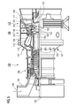
- FIG. 5 shows by way of example a gas turbine 100 in a longitudinal partial section.
- the gas turbine 100 has inside a rotatably mounted about a rotation axis 102 rotor 103 with a shaft 101, which is also referred to as a turbine runner.
- an intake housing 104 a compressor 105, for example, a toroidal combustion chamber 110, in particular annular combustion chamber, with a plurality of coaxially arranged burners 107, a turbine 108 and the exhaust housing 109th
- a compressor 105 for example, a toroidal combustion chamber 110, in particular annular combustion chamber, with a plurality of coaxially arranged burners 107, a turbine 108 and the exhaust housing 109th
- the annular combustion chamber 110 communicates with an annular annular hot gas channel 111, for example. There, for example, form four successive turbine stages 112, the turbine 108th
- Each turbine stage 112 is formed, for example, from two blade rings. As seen in the direction of flow of a working medium 113, in the hot gas channel 111 of a row of guide vanes 115, a series 125 formed of rotor blades 120 follows.
- the guide vanes 130 are fastened to an inner housing 138 of a stator 143, whereas the moving blades 120 of a row 125 are attached to the rotor 103 by means of a turbine disk 133, for example.
- air 105 is sucked in and compressed by the compressor 105 through the intake housing 104.
- the compressed air provided at the turbine-side end of the compressor 105 is supplied to the burners 107 where it is mixed with a fuel.
- the mixture is then burned to form the working fluid 113 in the combustion chamber 110.
- the working medium 113 flows along the hot gas channel 111 past the guide vanes 130 and the rotor blades 120.
- the working medium 113 expands in a pulse-transmitting manner so that the rotor blades 120 drive the rotor 103 and drive the machine coupled to it.
- the components exposed to the hot working medium 113 are subject to thermal loads during operation of the gas turbine 100.
- the guide vanes 130 and rotor blades 120 of the first turbine stage 112, viewed in the flow direction of the working medium 113, are subjected to the greatest thermal stress in addition to the heat shield elements lining the annular combustion chamber 110.
- substrates of the components may have a directional structure, i. they are monocrystalline (SX structure) or have only longitudinal grains (DS structure).
- iron-, nickel- or cobalt-based superalloys are used as the material for the components, in particular for the turbine blade 120, 130 and components of the combustion chamber 110.
- the blades 120, 130 may be anti-corrosion coatings (MCrAlX; M is at least one element of the group iron (Fe), cobalt (Co), nickel (Ni), X is an active element and is yttrium (Y) and / or silicon , Scandium (Sc) and / or at least one element of the rare earth or hafnium).
- M is at least one element of the group iron (Fe), cobalt (Co), nickel (Ni)
- X is an active element and is yttrium (Y) and / or silicon , Scandium (Sc) and / or at least one element of the rare earth or hafnium).
- Such alloys are known from the EP 0 486 489 B1 .
- EP 0 412 397 B1 or EP 1 306 454 A1 are known from the EP 0 486 489 B1 .
- MCrAlX may still be present a thermal barrier coating, and consists for example of ZrO 2 , Y 2 O 3 -ZrO 2 , ie it is not, partially or completely stabilized by yttria and / or calcium oxide and / or magnesium oxide.
- Electron beam evaporation produces stalk-shaped grains in the thermal barrier coating.
- the vane 130 has a guide vane foot (not shown here) facing the inner housing 138 of the turbine 108 and a vane head opposite the vane foot.
- the vane head faces the rotor 103 and fixed to a mounting ring 140 of the stator 143.
Landscapes
- Physics & Mathematics (AREA)
- Health & Medical Sciences (AREA)
- Life Sciences & Earth Sciences (AREA)
- Chemical & Material Sciences (AREA)
- Analytical Chemistry (AREA)
- Biochemistry (AREA)
- General Health & Medical Sciences (AREA)
- General Physics & Mathematics (AREA)
- Immunology (AREA)
- Pathology (AREA)
- Turbine Rotor Nozzle Sealing (AREA)
Priority Applications (2)
| Application Number | Priority Date | Filing Date | Title |
|---|---|---|---|
| EP10189665A EP2447708A1 (fr) | 2010-11-02 | 2010-11-02 | Détection de fissure à l'aide d'un prétraitement cryotechnique |
| PCT/EP2011/067813 WO2012059306A1 (fr) | 2010-11-02 | 2011-10-12 | Détection de fissures au moyen d'un prétraitement cryotechnique |
Applications Claiming Priority (1)
| Application Number | Priority Date | Filing Date | Title |
|---|---|---|---|
| EP10189665A EP2447708A1 (fr) | 2010-11-02 | 2010-11-02 | Détection de fissure à l'aide d'un prétraitement cryotechnique |
Publications (1)
| Publication Number | Publication Date |
|---|---|
| EP2447708A1 true EP2447708A1 (fr) | 2012-05-02 |
Family
ID=43568271
Family Applications (1)
| Application Number | Title | Priority Date | Filing Date |
|---|---|---|---|
| EP10189665A Withdrawn EP2447708A1 (fr) | 2010-11-02 | 2010-11-02 | Détection de fissure à l'aide d'un prétraitement cryotechnique |
Country Status (2)
| Country | Link |
|---|---|
| EP (1) | EP2447708A1 (fr) |
| WO (1) | WO2012059306A1 (fr) |
Cited By (1)
| Publication number | Priority date | Publication date | Assignee | Title |
|---|---|---|---|---|
| EP3333284A1 (fr) * | 2016-12-08 | 2018-06-13 | Siemens Aktiengesellschaft | Procédé d'évaluation non destructive de la microstructure de revêtements segmentés |
Citations (15)
| Publication number | Priority date | Publication date | Assignee | Title |
|---|---|---|---|---|
| US3567651A (en) * | 1965-02-03 | 1971-03-02 | Nasa | Dye penetrant for surfaces subsequently contacted by liquid oxygen |
| US4621193A (en) * | 1984-11-21 | 1986-11-04 | Michael Van Hoye | Fluorescent penetrant crack detection |
| EP0486489B1 (fr) | 1989-08-10 | 1994-11-02 | Siemens Aktiengesellschaft | Revetement anticorrosion resistant aux temperatures elevees, notamment pour elements de turbines a gaz |
| GB2282455A (en) * | 1993-08-10 | 1995-04-05 | British Aerospace | Standard specimen for evaluating penetrants used in detecting metal flaws |
| EP0412397B1 (fr) | 1989-08-10 | 1998-03-25 | Siemens Aktiengesellschaft | Revêtement protecteur contenant du rhénium possédant une résistance plus grande à la corrosion et l'oxydation |
| EP0892090A1 (fr) | 1997-02-24 | 1999-01-20 | Sulzer Innotec Ag | Procédé de fabrication de structure smonocristallines |
| EP0786017B1 (fr) | 1994-10-14 | 1999-03-24 | Siemens Aktiengesellschaft | Couche de protection de pieces contre la corrosion, l'oxydation et les contraintes thermiques excessives, et son procede de production |
| WO1999067435A1 (fr) | 1998-06-23 | 1999-12-29 | Siemens Aktiengesellschaft | Alliage a solidification directionnelle a resistance transversale a la rupture amelioree |
| US6024792A (en) | 1997-02-24 | 2000-02-15 | Sulzer Innotec Ag | Method for producing monocrystalline structures |
| WO2000044949A1 (fr) | 1999-01-28 | 2000-08-03 | Siemens Aktiengesellschaft | Superalliage a base de nickel presentant une bonne usinabilite |
| EP1306454A1 (fr) | 2001-10-24 | 2003-05-02 | Siemens Aktiengesellschaft | Revêtement protecteur contenant du rhénium pour la protection d'un élément contre l'oxydation et la corrosion aux températures élevées |
| EP1319729A1 (fr) | 2001-12-13 | 2003-06-18 | Siemens Aktiengesellschaft | Pièce résistante à des températures élevées réalisé en superalliage polycristallin ou monocristallin à base de nickel |
| EP1204776B1 (fr) | 1999-07-29 | 2004-06-02 | Siemens Aktiengesellschaft | Piece resistant a des temperatures elevees et son procede de production |
| US20050126256A1 (en) * | 2003-12-16 | 2005-06-16 | Fina Technology, Inc. | Accelerated method to determine or predict failure time in polyethylenes |
| EP1878707A1 (fr) * | 2006-07-14 | 2008-01-16 | Jenoptik Automatisierungstechnik GmbH | Procédé de production des fissures observables induites par laser dans de matériau fragile |
-
2010
- 2010-11-02 EP EP10189665A patent/EP2447708A1/fr not_active Withdrawn
-
2011
- 2011-10-12 WO PCT/EP2011/067813 patent/WO2012059306A1/fr not_active Ceased
Patent Citations (15)
| Publication number | Priority date | Publication date | Assignee | Title |
|---|---|---|---|---|
| US3567651A (en) * | 1965-02-03 | 1971-03-02 | Nasa | Dye penetrant for surfaces subsequently contacted by liquid oxygen |
| US4621193A (en) * | 1984-11-21 | 1986-11-04 | Michael Van Hoye | Fluorescent penetrant crack detection |
| EP0486489B1 (fr) | 1989-08-10 | 1994-11-02 | Siemens Aktiengesellschaft | Revetement anticorrosion resistant aux temperatures elevees, notamment pour elements de turbines a gaz |
| EP0412397B1 (fr) | 1989-08-10 | 1998-03-25 | Siemens Aktiengesellschaft | Revêtement protecteur contenant du rhénium possédant une résistance plus grande à la corrosion et l'oxydation |
| GB2282455A (en) * | 1993-08-10 | 1995-04-05 | British Aerospace | Standard specimen for evaluating penetrants used in detecting metal flaws |
| EP0786017B1 (fr) | 1994-10-14 | 1999-03-24 | Siemens Aktiengesellschaft | Couche de protection de pieces contre la corrosion, l'oxydation et les contraintes thermiques excessives, et son procede de production |
| EP0892090A1 (fr) | 1997-02-24 | 1999-01-20 | Sulzer Innotec Ag | Procédé de fabrication de structure smonocristallines |
| US6024792A (en) | 1997-02-24 | 2000-02-15 | Sulzer Innotec Ag | Method for producing monocrystalline structures |
| WO1999067435A1 (fr) | 1998-06-23 | 1999-12-29 | Siemens Aktiengesellschaft | Alliage a solidification directionnelle a resistance transversale a la rupture amelioree |
| WO2000044949A1 (fr) | 1999-01-28 | 2000-08-03 | Siemens Aktiengesellschaft | Superalliage a base de nickel presentant une bonne usinabilite |
| EP1204776B1 (fr) | 1999-07-29 | 2004-06-02 | Siemens Aktiengesellschaft | Piece resistant a des temperatures elevees et son procede de production |
| EP1306454A1 (fr) | 2001-10-24 | 2003-05-02 | Siemens Aktiengesellschaft | Revêtement protecteur contenant du rhénium pour la protection d'un élément contre l'oxydation et la corrosion aux températures élevées |
| EP1319729A1 (fr) | 2001-12-13 | 2003-06-18 | Siemens Aktiengesellschaft | Pièce résistante à des températures élevées réalisé en superalliage polycristallin ou monocristallin à base de nickel |
| US20050126256A1 (en) * | 2003-12-16 | 2005-06-16 | Fina Technology, Inc. | Accelerated method to determine or predict failure time in polyethylenes |
| EP1878707A1 (fr) * | 2006-07-14 | 2008-01-16 | Jenoptik Automatisierungstechnik GmbH | Procédé de production des fissures observables induites par laser dans de matériau fragile |
Non-Patent Citations (1)
| Title |
|---|
| PETERS ET AL: "Evaluation of the effects of carbon dioxide used as a pulpal test. I. In vitro effect on human enamel", JOURNAL OF ENDODONTICS, LIPPINCOTT WILLIAMS & WILKINS, PHILADELPHIA, PA, US, vol. 9, no. 6, 1 June 1986 (1986-06-01), pages 219 - 227, XP022468712, ISSN: 0099-2399, DOI: 10.1016/S0099-2399(86)80017-6 * |
Cited By (2)
| Publication number | Priority date | Publication date | Assignee | Title |
|---|---|---|---|---|
| EP3333284A1 (fr) * | 2016-12-08 | 2018-06-13 | Siemens Aktiengesellschaft | Procédé d'évaluation non destructive de la microstructure de revêtements segmentés |
| WO2018103993A1 (fr) * | 2016-12-08 | 2018-06-14 | Siemens Aktiengesellschaft | Procédé non destructif pour évaluer la microstructure de revêtements segmentés |
Also Published As
| Publication number | Publication date |
|---|---|
| WO2012059306A1 (fr) | 2012-05-10 |
Similar Documents
| Publication | Publication Date | Title |
|---|---|---|
| EP2593582B1 (fr) | Système stratifié céramique poreux | |
| EP2569594B1 (fr) | Analyse de surface pour la détection de trous fermés et procédé de réouverture | |
| EP2314987A1 (fr) | Analyse de surfaces pour la détection de trous fermés et dispositif | |
| EP2330230A1 (fr) | Matériel de masquage, couche de masquage, procédé de masquage d'un substrat et procédé de revêtement d'un substrat | |
| EP1952931A1 (fr) | Mechtrode ayant une alimentation en poudre et procédé d'utilisation de cette mechtrode | |
| EP2450465A1 (fr) | Système de couche poreux doté d'une couche intérieure poreuse | |
| EP2312267A1 (fr) | Procédé de mesure de l'épaisseur de couche par triangulation laser et dispositif | |
| EP2733310A1 (fr) | Surface modifiée autour d'un trou | |
| EP2216509A1 (fr) | Composant de turbine doté d'une couche de protection pouvant être enlevée simplement, ensemble de composants de turbines, turbine et procédé de protection d'un composant de turbine | |
| EP2186594A1 (fr) | Procédé et dispositif de préchauffage lors du soudage utilisant un deuxième faisceau laser | |
| EP2581472A1 (fr) | Couche double céramique à base d'oxyde de zirconium | |
| EP2062672A1 (fr) | Méthode de brasage de fissures larges | |
| EP2254726A2 (fr) | Élément à soudures superposées et procédé de production correspondant | |
| EP2365106A1 (fr) | Système de couche d'isolation thermique en céramique doté d'une couche de raccordement modifiée | |
| EP2241397A1 (fr) | Soudage de trous, procédé de revêtement de tiges de soudage | |
| EP2224039A1 (fr) | Revêtement doté d'un procédé de revêtement thermique et non thermique | |
| EP2584067A1 (fr) | Composant avec graphène et procédé de fabrication de composants avec graphène | |
| EP2583784A1 (fr) | Préparation d'au moins un poste à souder avant le soudage et composant | |
| EP2312122A1 (fr) | Détermination d'une référence pour l'établissement de la position de trous bouchés, dispositif et dispositif d'usinage | |
| EP2386824A1 (fr) | Analyse de surface pour la détection de trous fermés et procédé de réouverture | |
| EP2431736A1 (fr) | Procédé pour tester le fonctionnement d'une installation thermographique développée pour l'exécution d'un procédé de thermographie, composant de test correspondant et son procédé de fabrication | |
| EP2053145A1 (fr) | Procédé d'enlèvement d'une couche métallique à l'aide de FIC dans une étape intermédiaire | |
| EP2597259A1 (fr) | Surface modifiée autour d'un trou | |
| EP2447708A1 (fr) | Détection de fissure à l'aide d'un prétraitement cryotechnique | |
| EP1978790B1 (fr) | Dispositif et procédé destinés au revêtement d'un composant doté d'un dispositif d'ajustement |
Legal Events
| Date | Code | Title | Description |
|---|---|---|---|
| PUAI | Public reference made under article 153(3) epc to a published international application that has entered the european phase |
Free format text: ORIGINAL CODE: 0009012 |
|
| AK | Designated contracting states |
Kind code of ref document: A1 Designated state(s): AL AT BE BG CH CY CZ DE DK EE ES FI FR GB GR HR HU IE IS IT LI LT LU LV MC MK MT NL NO PL PT RO RS SE SI SK SM TR |
|
| AX | Request for extension of the european patent |
Extension state: BA ME |
|
| RAP1 | Party data changed (applicant data changed or rights of an application transferred) |
Owner name: SIEMENS AKTIENGESELLSCHAFT |
|
| STAA | Information on the status of an ep patent application or granted ep patent |
Free format text: STATUS: THE APPLICATION IS DEEMED TO BE WITHDRAWN |
|
| 18D | Application deemed to be withdrawn |
Effective date: 20121103 |